Installation, Operation and Maintenance Instructions
– Read and Save These Instructions –
This manual is provided to acquaint you with the dehumidifier so that installation,
operation and maintenance can proceed successfully.
Ultimate satisfaction depends on the quality of installation and a
thorough understanding of this equipment. The dehumidifier is built around tested
engineering principles and has passed thorough internal and 3rd party inspections for
quality of workmanship and function.
Installation, Operation and Maintenance Instructions
– Read and Save These Instructions –
1
Water Removal Rate (Pints/Day)
70 pints 80˚F, 60% (AHAM)
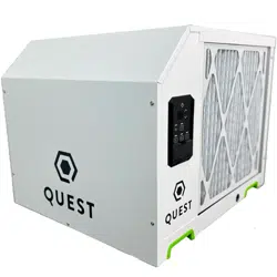
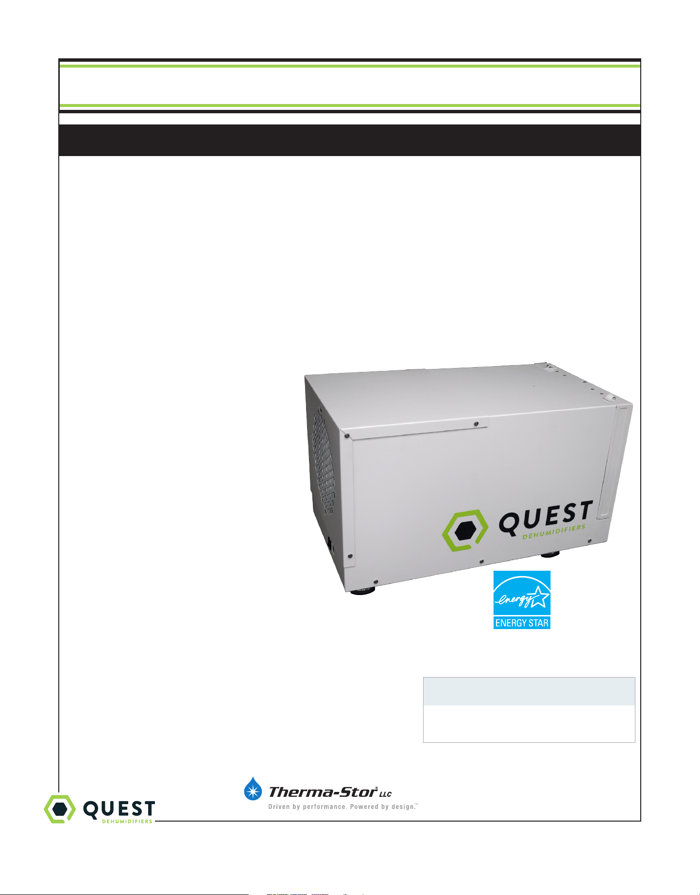
Quest 70
FEATURES:
• Energy Star Listed
• Large Capacity
• MERV-13 Filtration
• Low Temperature Operation
• Low Voltage Control
• Carbon Filtration
• Optional Equipment
– Ducting Kit
– Hang Kit
– Caster Kit
– Condensate Pump
Quest 70
TS-1010
10/17 Rev. B
4201 Lien Rd Phone 608-237-8400
Madison, WI 53704 Toll-Free 1-877-420-1330
www.QuestHydro.com [email protected]
Specifications subject to change without notice.

2
1-877-420-1330
www.QuestHydro.com
info@QuestHydro.com
Quest 70 Installation, Operation and Maintenance Instructions
Table of Contents
Introduction ............................................................................... 1
Features & Benefits .................................................................. 1
Safety Precautions ................................................................... 3
1. Intended Application ............................................................4
2. Registrations .........................................................................4
3. Specifications .......................................................................4
4 . Installation ........................................................................... 5
4.1 Installation Checklist ....................................................5
4.1A Power Accessibility ............................................... 5
4.1B Space ...................................................................... 5
4.1C Low Voltage Wiring ..............................................5
4.1D Back-Draft Damper .............................................5
4.1E Support Structure and Suspension ...................... 5
4.2 Electrical Requirements .............................................. 5
4.3 Condensate Removal ................................................... 6
4.3A Lifting Condensate ..............................................6
4.3B Condensate Pump Kit ......................................... 6
4.4 Ducting ........................................................................ 6
4.4A Fresh Air/Supply Air ............................................ 8
4.4B Ducting for Fresh Air - Option ..........................8
4.4C Installation in a Basement or Crawlspace ..........8
4.4D Installation in an Attic ......................................... 9
4.4E Installation in a Structure with
No Forced Air HVAC System .................................... 10
4.4F Ducting for High Eciency Filtration .............. 10
4.5 Compressor Release and Noise Abatement ............ 10
4.6 Controls ...................................................................... 10
5. Control Package Diagram Sheet ........................................ 12
6. Maintenance ........................................................................ 13
6.1 High Eciency Air Filter ............................................13
6.2 Optional Fresh Air Intake ...........................................13
7. Wiring Diagrams .................................................................. 14
8. Optional Parts List ..............................................................15
9. Service Parts List ...............................................................15
Routine Maintenance .........................................................15
10. Service ................................................................................ 16
10.1 Technical Description ................................................. 16
10.2 Troubleshooting .........................................................16
10.3 Refrigerant Charging ................................................17
10.4 Compressor/Capacitor Replacement .....................18
10.5 Electric Ventilation Damper ....................................18
Warranty ..................................................................................19

3
1-877-420-1330
www.QuestHydro.com
info@QuestHydro.com
Quest 70 Installation, Operation and Maintenance Instructions
Safety Precautions
Read the installation, operation and maintenance instructions carefully before installing and operating this device.
Proper adherence to these instructions is essential to obtain maximum benefit from your Quest 70.
READ AND SAVE THESE INSTRUCTIONS
• The device is designed to be installed INDOORS IN A SPACE THAT IS
PROTECTED FROM RAIN AND FLOODING.
• Install the unit with space to access the front panel for maintenance
and service. DO NOT INSTALL UNIT WITH THE FRONT PANEL
INACCESSIBLE.
• Avoid directing the discharge air at people, or over the water in pool areas.
• If used near a water source; be certain there is no chance the unit could fall
into the water or get wet. The unit should also be plugged into a GFCI (Ground
Fault Circuit Interrupt) outlet.
• DO NOT use the device as a bench or table.
• DO NOT place the device directly on structural members.
• A drain pan MUST be placed under the unit if installed above a living area or
above an area where water leakage could cause damage (see local regularity
code for more information).
• Never operate a unit with a damaged power cord. If the power cord is damaged
it must be replaced by the manufacturer, its service agent, or similarly qualified
person in order to avoid a hazard.
• The unit shall be installed in accordance with national wiring regulations.
• Do not obstruct the air intake and exhaust. Maintain a .3 m (1 ft) clearance
around the air intake and exhaust.
• This appliance is not intended for use by persons (including children) with
reduced physical, sensory or mental capabilities, or lack of experience and
knowledge, unless they have been given supervision or instruction concerning
use of the appliance by a person responsible for their safety. Children should be
supervised to ensure that they do not play with the appliance.
FOR HVAC INSTALLER AND OWNER
Quest 70 Installation, Operation and Maintenance Instructions
4
1-877-420-1330
www.QuestHydro.com
info@QuestHydro.com
Quest 70 Installation, Operation and Maintenance Instructions
1. Intended Application for Quest 70
For the ideal installation, draw air from the central part of the workspace and return it to isolated areas of the structure. The
ductwork of the existing heating system can be used to supply air to the workspace.
2. Registrations
The Quest 70 conforms to unified standard UL 60335-2-40.
3. Specifications
FOR HVAC INSTALLER ONLY
4033750 Quest 70
Blower:
150 CFM @ 0.0” WG
Power:
680 Watts @ 80°F and 60% RH
Supply voltage:
110-120 VAC – 1phase – 60 Hz.
Current Draw:
5.1 Amps
Energy Factor:
2.37 L/kWh
Operating Temp:
33°F Min - 100°F Max
Minimum Performance @ 80°F and 60% RH:
Water Removal:
Eciency:
70 Pints/Day
5.0 Pints/kWh
Air Filter:
MERV-13 Size: 12" x 12" x 1"
Power Cord:
8’, 110-120 VAC, Ground
Drain Connection:
3/4” Threaded MPT
Dimensions:
Width:
Height:
Length:
Weight:
Unit Shipping
12" 15 5/8"
12” 16"
28" 31 5/8"
55 lbs 65 lbs
Quest 70 Installation, Operation and Maintenance Instructions
5
1-877-420-1330
www.QuestHydro.com
info@QuestHydro.com
Quest 70 Installation, Operation and Maintenance Instructions
4. Installation
4.1 Installation Checklist
CAUTION
Prior to installation of the Quest 70, please review the following requirements. The Quest 70 can be installed in a variety
of locations to meet the owner’s needs, and be integrated with existing forced air systems or existing ductwork if desired.
The location choice is contingent on a variety of requirements not limited to: ease of service, controls access, drainage,
filtration, power, fresh-air ventilation (optional), water damage prevention, and current regulatory codes (ASHRAE, fire,
etc). Please address all of these issues before you select the location of the device.
4.1A Power Accessibility
Unit should be located in an area where the cord’s length (8') should easily reach a 110-120 VAC electrical outlet with a
minimum of a 15 A circuit capacity.
4.1B Space
Location should have enough clearance to handle the unit’s overall dimensions as well as the necessary return/supply
ductwork to the unit.
4.1C Low Voltage Wiring
Unit location should be in an area where field wiring the remote controls (low voltage) to the unit will be possible.
4.1D Back-Draft Damper (P/N 4023647)
It is recommended that a back-draft damper be used in the discharge duct of the Quest 70, especially when connecting to
the supply ducting system. The back-draft damper prevents supply air from counter flowing through the Quest 70 when it
is not operating. The unit location should be chosen to allow installation of this accessory.
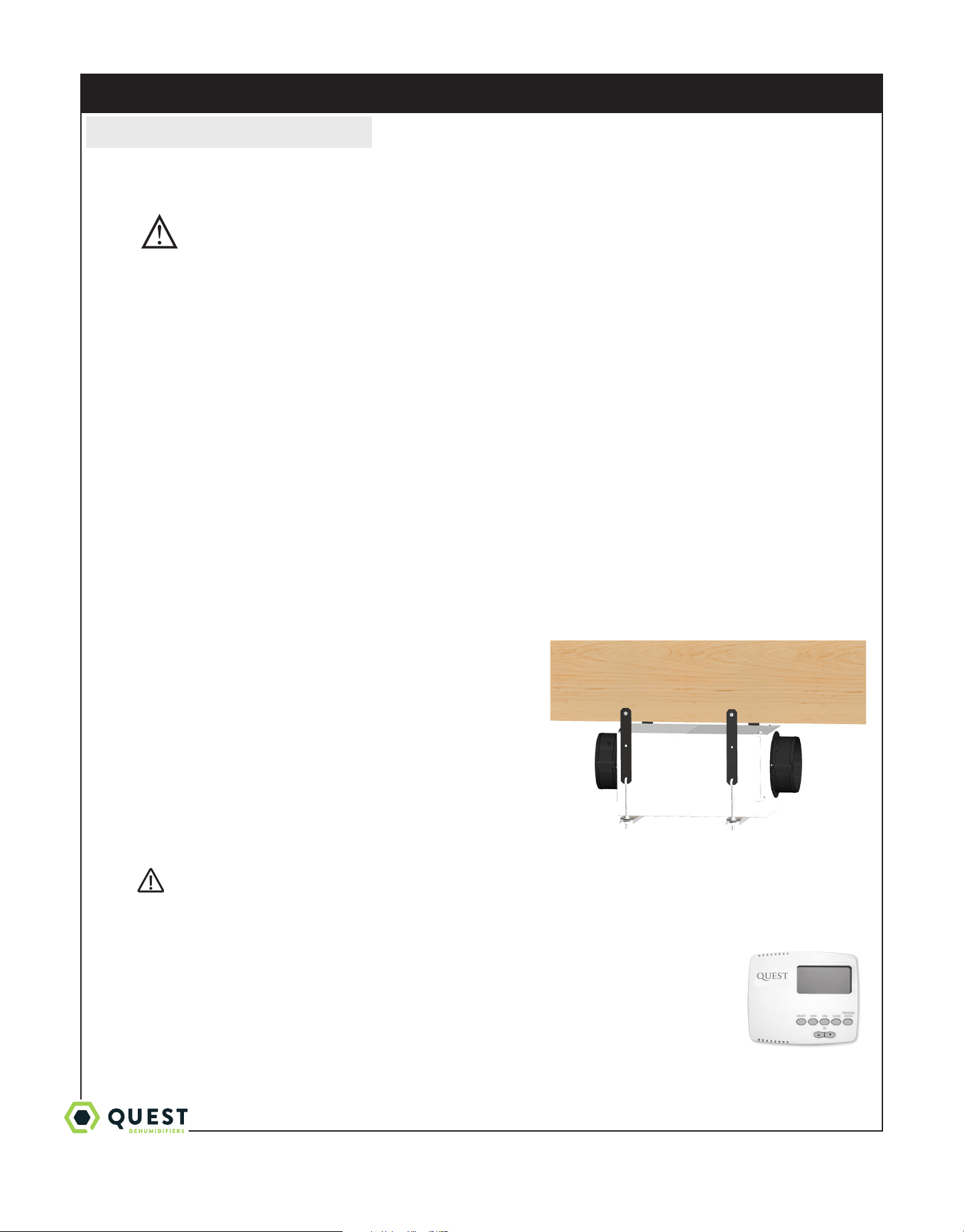
4.1E Support Structure and Suspension
Place the Quest 70 on supports to raise the base of the unit. Do not
place the Quest 70 directly on structural building members without
vibration absorbers or unwanted noise may result.
The Quest 70 may be suspended with a hang kit (4028111) or a
suitable alternative from structural members, as long as the suspending
assembly supports the Quest 70’s base in its entirety. Do not hang the
Quest 70 from the cabinet. Remember to place a drain pan under the
unit if it is suspended above a finished area or above an area where water
leakage could cause damage.
4.2 Electrical Requirements
WARNING!
WARNING: DO NOT ALLOW THE YELLOW LEAD FROM THE Quest TO CONTACT THE
RED LEAD FROM THE Quest OR DAMAGE TO THE TRANSFORMER WILL RESULT.
The Quest 70 plugs into a common grounded 115VAC outlet. The device draws 5.1 Amps under normal
operating conditions. If used in an area which may become wet, a GFCI (Ground Fault Interrupt) outlet
is required. Please, consult local electrical codes for any further information.
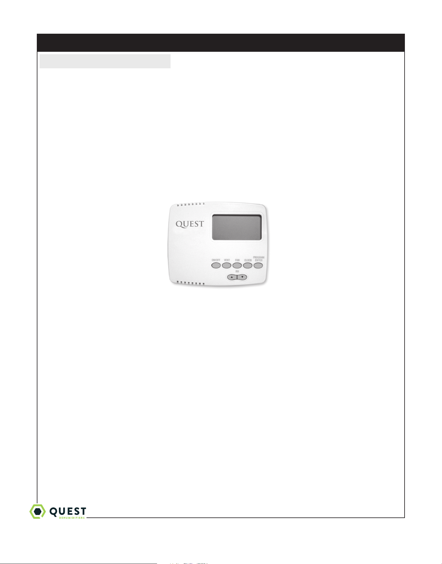
Therma-Stor LLC oers a family of control devices for use with the Quest 70. The controls are to
be located remotely from the unit and located in the space to be conditioned. The controls are low
voltage (24 volt) and should be connected to the Quest 70 with low voltage wire (thermostat or other
appropriate).
Hang Kit (4029908) shown suspending a Quest 70. Available
from your dealer or call 1-800-533-7533.
Quest DEH 3000
Digital Control (P/N
4027370)
Call 1-800-533-7533
FOR HVAC INSTALLER ONLY
Quest 70 Installation, Operation and Maintenance Instructions
6
1-877-420-1330
www.QuestHydro.com
info@QuestHydro.com
Quest 70 Installation, Operation and Maintenance Instructions
CAUTION
Do not install the control panel where it may not accurately sense the relative humidity such as near HVAC supply
registers, near exterior doors, on an outside wall, near a window, or near a water source.
The installer must supply the wiring between the Quest 70 and the control panel. Be sure to safely route the control
wiring to prevent damage during installation.
CAUTION
Do not cross wires when connecting the Quest 70 and the remote control panel or damage to the transformer may
result. The remote controls of the Quest 70 are powered by a low voltage circuit (24VAC) and must NEVER contact or
be connected to a high voltage circuit.
The control wires leaving the Quest 70 and the remote control panels are numbered and color-coded to prevent
confusion. Some of the control wires leaving the Quest 70 may not be used with certain control panels and should be left
unconnected with wire nuts taped onto the stripped ends for safety. Be sure to consult the electrical schematic in this
manual or inside the access panel of the Quest 70 before making control connections.
4.3 Condensate (Water) Removal
CAUTION
A trap in the drain line is preferred, but not required for the unit to drain properly. Local codes may require a trap. Use
care to keep the pipe assembly as flat to the floor as possible. Kinks and/or humps will prevent proper drainage.
The Quest 70 generates condensate. Install a 3/4" male nominal pipe thread adapter to the drain pan. It is necessary to
assemble your own drain pipe assembly utilizing 3/4" PVC pipe to get the condensate to a floor or other drain. Pipe is
commonly available in 10’ lengths from building supply, plumbing or hardware stores. Slope to drain should be at least 1”
drop for every 10’ of run.
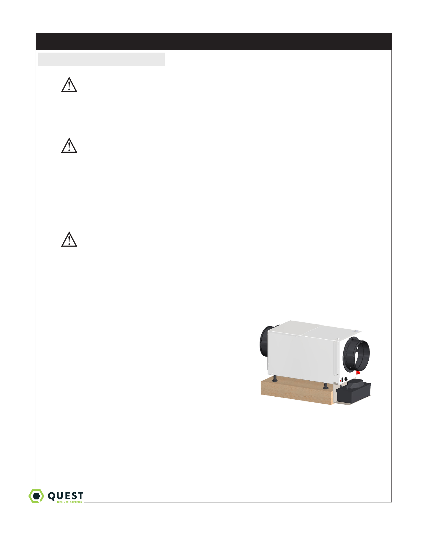
4.3A Lifting Condensate
A condensate pump may installed if lift is required to dispose of the
condensate.
4.3B Condensate Pump Kit (4030113)
A condensate pump kit is available from the factory for use with the
Quest 70 and provides 15' of lift. Condensate is automatically pumped
to a remote location when the water level in the pump’s reservoir rises to
close the float switch. The pump also contains a safety float switch. The
white leads from this switch extend from beneath the pump cover. This
switch should be installed in series with the field wire that connects the
blue (#5) lead from the Quest 70 to the the control panel. If the pump
fails, this switch opens the compressor control circuit and stops water
production before the reservoir overflows. The Quest 70 will continue to
ventilate or circulate air as normal, but will not dehumidify until this switch
closes.
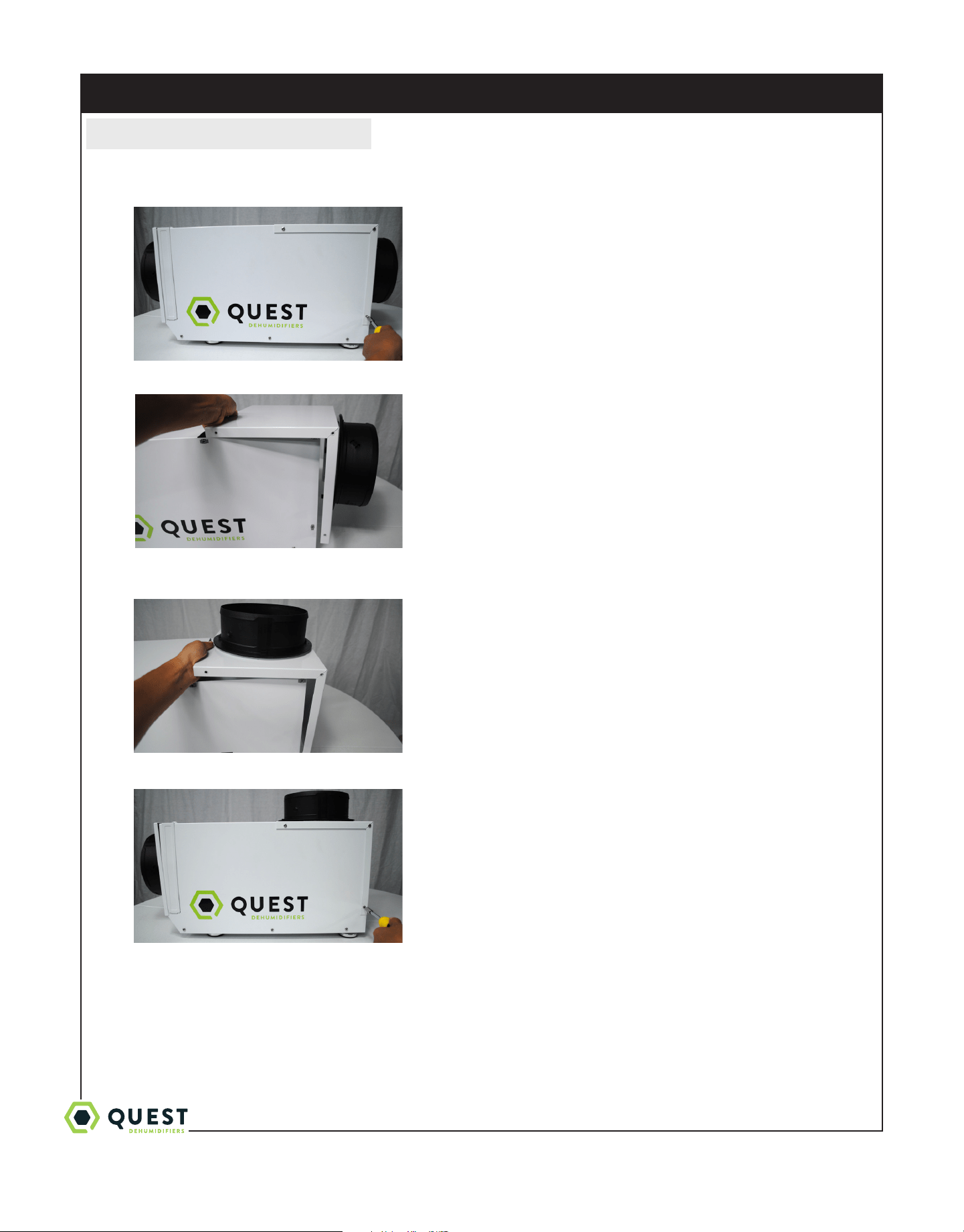
4.4 Converting to Vertical Discharge Airflow
The QuestDry 70 is shipped from the factory with the exhaust panel of the cabinet configured for horizontal air
discharge. The cabinet can be easily converted to vertical air discharge. To convert the air discharge from horizontal to
vertical, follow these steps:
Condensate Pump Kit (4030113) shown installed. Available from
your dealer or call 1-800-533-7533.
FOR HVAC INSTALLER ONLY
Quest 70 Installation, Operation and Maintenance Instructions
7
1-877-420-1330
www.QuestHydro.com
info@QuestHydro.com
Quest 70 Installation, Operation and Maintenance Instructions
1. Using T-20 Torx Driver, remove three (3) sheet metal screws that attach the exhaust panel from each side of the
Quest 70. There will be a total of six (6) screws. Do not remove the exhaust collar.
2. Remove the exhaust panel.
3. Rotate the exhaust panel so that the exhaust collar is located on the top of the unit. Align screw holes and snap the
panel onto the base.
4. Secure the exhaust panel to the base by replacing the six (6) screws.
For the ideal installation, draw air from the central part of the workspace and return it to the isolated areas of the
workspace like the bedrooms, den, utility room, or family room. The ductwork of the existing heating system can be used
to supply air to the workspace. If the existing supply goes to isolated areas of the structure, discharge the supply of the
Quest 70 into the supply of the existing heating system. Installation of a separate supply duct to the Quest 70 from a
central area is recommended.
FOR HVAC INSTALLER ONLY
Quest 70 Installation, Operation and Maintenance Instructions
8
1-877-420-1330
www.QuestHydro.com
info@QuestHydro.com
4.4A Supply Air
CAUTION
DO NOT draw air directly from the kitchen, laundry, or isolated basement.
You may draw air from a basement that is open to the workspace. All flexible ducting connected to the Quest 70 should
be UL listed.
A short piece of flexible ducting on all Quest 70 duct connections is recommended to reduce noise and vibration
transmitted to rigid ductwork in the structure. Ducting the Quest 70 as mentioned requires consideration of the
following points:
Duct Sizing: For total duct lengths up to 25', use a minimum 8" diameter round or equivalent rectangular. For longer
lengths, use a minimum 10" diameter or equivalent. Grills or diusers on the duct ends must not excessively restrict
airflow.
Connecting to existing HVAC systems: An optional 8" check backdraft damper is available from the factory to prevent
reverse air flow through the Quest 70. If the Quest 70 is ducted to the supply of an air handler, the check damper should
be placed in the Quest 70 supply duct.
CAUTION
Contact the factory when connecting to a static pressure of greater than or equal to +.5" WG.
4.4B Ducting for Fresh Air — Option
Fresh air may be brought into the structure by connecting an insulated duct from outside the structure to the 6" inlet of
the Quest 70. Advantages of this form of ventilation include:
1. Outside air is filtered before entering the building.
2. Outside air will be dehumidified before entering the building if the Quest 70 is running in dehumidification mode.
3. Drawing air from outside and blowing inside aids in slightly pressurizing the structure. This helps prevent dirty and
humid air from entering elsewhere. It also reduces the potential for carcinogenic radon gas to enter and provides a
small amount of make-up air for open combustion and exhaust devices like the clothes drier, fireplace, and water
heater.
4. Exhaust fans are recommended in the bath rooms and kitchen.
In cold climates or areas where the outdoor dew point is low at times, ventilation can be used to dehumidify the structure,
making the Quest 70 capable of year-round drying. This is accomplished by bringing the dry, low dew point air into the
structure during these times. This approach is often more economical than running the dehumidifier to remove excess
moisture from the structure. In cold climates, adequately ventilating is critical to reduce the inside moisture content and
avoid moisture accumulating in the wall cavities. TIP: If your structure experiences condensation on the interior surface
of the windows during the winter, increasing the amount of ventilation will often solve the problem.
An insulated 6" diameter duct is generally sucient to provide up to 70 CFM of outside air. Large quantities of outside
air will impact Quest 70 performance positively or negatively, depending upon the inside and outside air conditions.
The outside air duct should be connected to the front of the unit. With a standard tee, the amount of outside air can be
restricted with a blade damper.
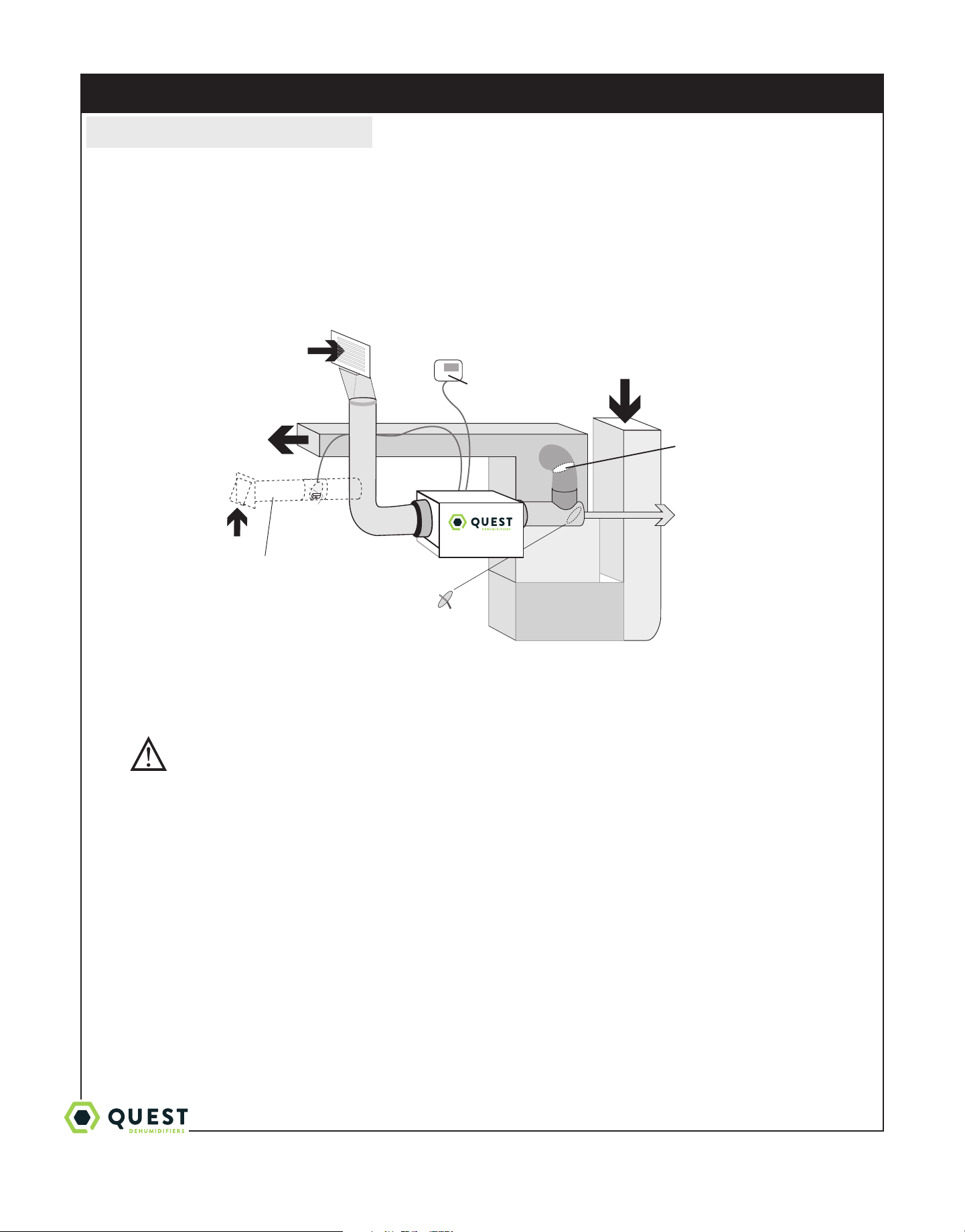
4.4C Installation in a Basement or Crawlspace with an Existing Forced Air HVAC System.
FOR HVAC INSTALLER ONLY
Quest 70 Installation, Operation and Maintenance Instructions
9
1-877-420-1330
www.QuestHydro.com
info@QuestHydro.com
Quest 70
Indoor Air
Return
Quest DEH 3000
control
Heating/AC Return Air
Backdraft
Damper
Dry Air to
Basement
Gravity
Damper
Motorized
Damper
Optional
Fresh Air
Intake
Basement Installation: Install a separate 8" return for the Quest 70 in a central area of the structure. Optional: Duct the
supply of the Quest to a 8" x 8" x 8" tee/damper, adjusted to 20% open to the basement. Duct the other side of the tee to
the air supply of the existing HVAC system with a backdraft damper.
Crawlspace Installation: Install a separate return for the Quest 70 in a central area of the structure. Optional: Duct the
supply of the Quest 70 to a 8" x 8" x 8" tee/damper that is 20% open to the crawlspace if desired. Duct the other side of
the tee to the air supply of the existing HVAC system with a backdraft damper.
Instead of installing a separate return to the Quest 70, and if the existing system has multiple returns, it is possible to
select one to disconnect from the existing forced air system and use it for the dedicated Quest return. Always select
a return from a central location in the structure in an area that is always open to the rest of the structure. Do not use a
return from a room that may have its door closed much of the time or, alternatively, install a separate return from the open
part of the structure.
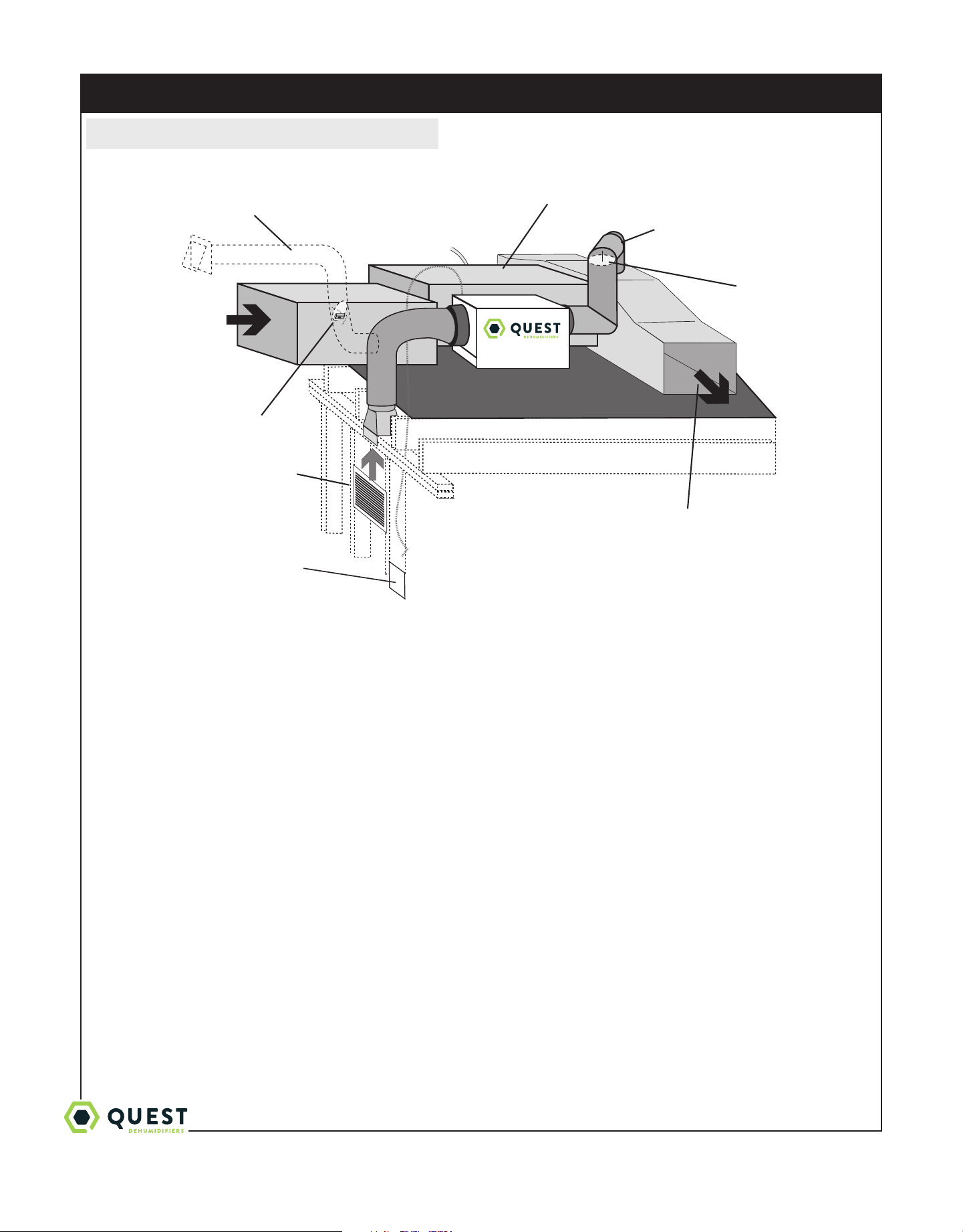
4.4D Installation in an Attic with an Existing Forced Air HVAC System
CAUTION
ALWAYS place a drain pan under the unit if it is suspended above a finished area or above an area where water leakage
could cause damage.
The preferred method of installation is to create a separate return for the Quest 70 in a central area of the structure. Duct
the supply of the Quest 70 to the air supply of the existing HVAC system.
FOR HVAC INSTALLER ONLY
Quest 70 Installation, Operation and Maintenance Instructions
10
1-877-420-1330
www.QuestHydro.com
info@QuestHydro.com
4.4E Installation in a Structure with No Existing Forced Air HVAC System
When installing the Quest 70 in a structure that does not have a forced air HVAC system, a single return for the Quest
70 should be installed in central open area of the structure. DO NOT locate the return in a bathroom or a kitchen. The
supplies of the Quest 70 should be located in the remote areas of the structure. By ducting this way, the air inside the
structure will circulate through the Quest 70 to be filtered and dehumidified. A 6" diameter duct is recommended for
branches to the remote rooms. A 8" diameter duct is recommended for branches to larger areas.
4.4F Ducting for High Eciency Filtration
The Quest 70 is equipped with a high eciency MERV 13 media filter (P/N 4037724). For optimal performance it is
recommended that the filter be replaced every 3-6 months.
4.5 Noise Abatement
A length of 10 feet or more of flex ducting on the outlet of the Quest 70 will reduce air noise from the fan. A length of
flexible ducting on all Quest 70 duct connections is recommended to reduce noise transmitted to rigid ductwork in the
structure.
4.6 Controls
The Quest 70 features a built-in dehumidistat control as well as the ability to wire a remote mounted control to the unit.
The control used to operate the unit should be located in an area where the control can accurately sense the humidity of
FOR HVAC INSTALLER AND OWNER
Quest
Indoor Air Return
Quest
Air Supply
Heating & A/C Unit
Indoor
Air
Return
Indoor Air Supply
Backdraft
Damper
Motorized
Damper
Optional
Fresh Air
Intake
Quest DEH 3000
control
Quest 70 Installation, Operation and Maintenance Instructions
11
1-877-420-1330
www.QuestHydro.com
info@QuestHydro.com
Control Part No. 4027370
FOR HVAC INSTALLER ONLY
the area where humidity control is desired.
If the Quest 70 is located in the area where humidity control is desired, consider using the built-in control. Adjust the
humidity control so that the unit maintains the desired level of humidity.
If the Quest 70 is located outside of the area where humidity control is desired, consider using a remote wired humidity
controller that is located in the area where humidity control is desired.
When using a remote wired dehumidistat, be sure the built-in dehumidistat is set to the o position by turning it
counterclokwise until it stops. Failure to do so may cause the unit to sense the humidity from the wrong area.
WARNING: DO NOT allow the yellow lead from the unit to contact the red lead or the white
lead from the unit or damage to the transformers will result.
The Quest dehumidifier is controlled using screw terminals.
FAN = Fan control
DEHU = Dehumidification (fan and compressor) control
COM = 24volt AC power transformer neutral side (common with DMPR)
DMPR = 24volt AC power transformer neutral side (common with COM)
24V = transformer high side
Between the COM/DMPR terminals and the 24V terminal is a 40VA transformer. This low voltage power source powers
the relay coils which control the fan and compressors. This 24VAC transformer can also be used to power HVAC assessories
external to the dehumidifier.
• To turn the dehumidifier on make contact between 24V and DEHU terminals.
• To turn the fan on make contact between 24V and FAN terminals.
• To power an HVAC accessory, connect the accessory to the DMPR (or COM) terminal and the 24V terminal.
Quest 70 Installation, Operation and Maintenance Instructions
12
1-877-420-1330
www.QuestHydro.com
info@QuestHydro.com
FOR HVAC INSTALLER AND OWNER
5 Control Package Diagram
WARNING: Allowing 24V terminal to contact COM or DMPR terminals will
destroy the transformer.
Dehumidifier on: Connect 24V and DEHU terminals.
Fan only on: Connect 24V and FAN terminals.
Accessory power: 24V AC power supply available for HVAC accessories between 24V terminal
and DMPR (or COM) terminal, COM and DMPR terminals are common with each other.
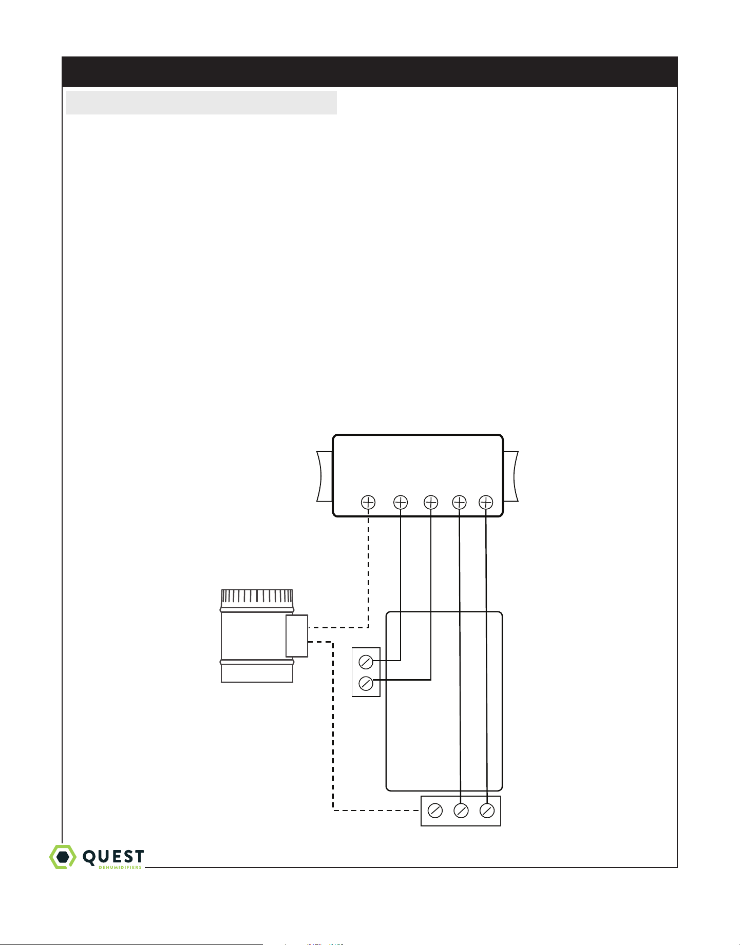
Quest DEH 3000 dehumidification & ventilation control
Quest
Dehumidifier
RED
YELLOW
BLUE
GREEN or BROWN
WHITE
Internal Connections
OPTIONAL
DAMPER
24 VAC
DMP COMP FAN
24V COM DEHU FANDMPR
Quest 70 Installation, Operation and Maintenance Instructions
13
1-877-420-1330
www.QuestHydro.com
info@QuestHydro.com
6. Maintenance
6.1 High Eciency Air Filter
The Quest 70 is equipped with a MERV 13 media filter. This filter should be checked every three months. Operating the
unit with a dirty filter will reduce dehumidifier capacity and eciency and may cause the compressor to cycle o and on
unnecessarily on the defrost control.
DO NOT operate the unit without a filter or with a less eective filter. Operating the unit without a filter or with a less
eective filter may cause internal damage to the unit and invalidate the product warranty.
6.2 Optional Fresh Air Intake
Check and clean the screen on the outdoor fresh air intake port seasonally. The screen may become plugged during the
seasons when there are many particles in the outdoor air.
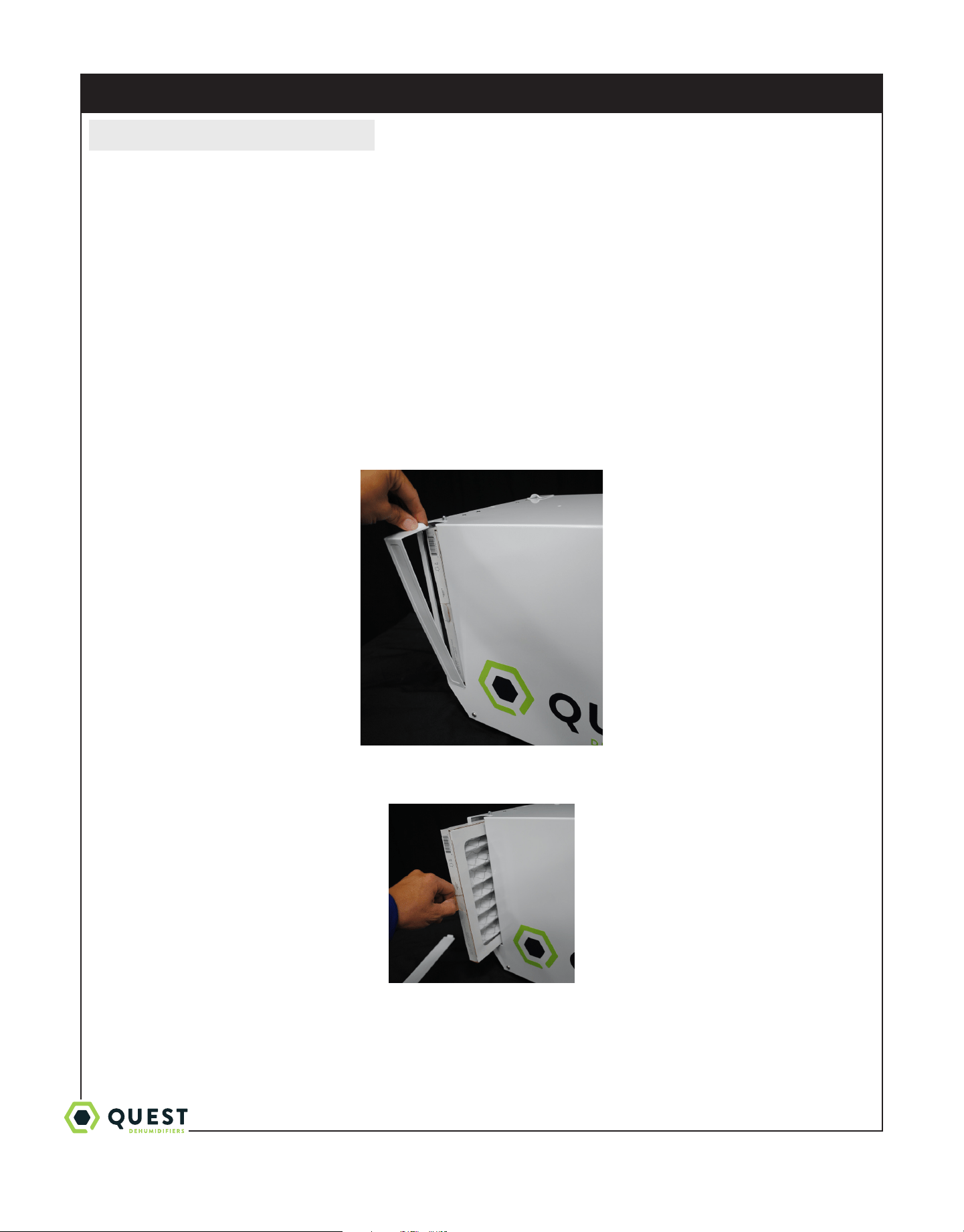
To replace the filter, remove the filter door from one of the sides of the Quest 70 by pushing the snap button in and
gently pulling to door away from the body of the unit, then pulling up to disengage the door flange from the slot,
removing the door.
Remove the filter by gently pulling straight out of the unit. Insert new filter in the same manner, pushing it gently
straight into the unit.
Replace filter door by inserting the bottom tab into the slot, aligning the door and pushing it gently against the unit until
the snap button secures the door.
FOR HVAC INSTALLER ONLY
Quest 70 Installation, Operation and Maintenance Instructions
14
1-877-420-1330
www.QuestHydro.com
info@QuestHydro.com
FOR HVAC INSTALLER ONLY
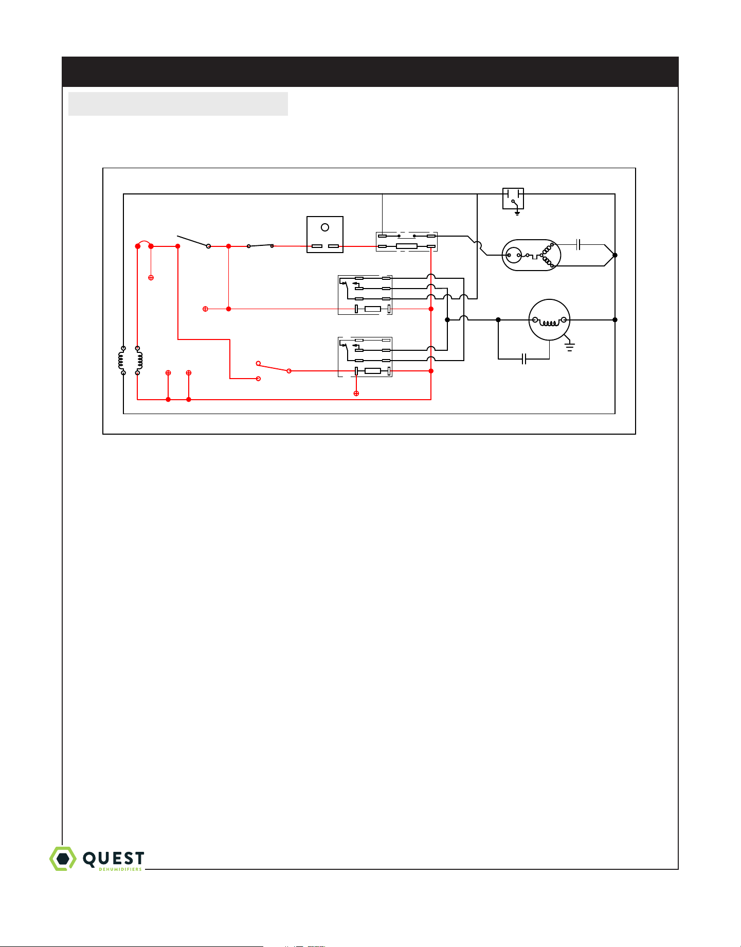
7. Wiring Diagram
BLU31 BLU32
BLK4
BLK6
GRY15
BLK5
YEL7
WHT3
RED8
BLU9
RED8
BLU9
WHT2
YEL33
YEL26
ORG23
GRN1
BRN11
BLK10
BLK10
GRN12
BLK13
BLK14
BLK13
GRY14 GRY15
ORG23
PNK16
RED17
RED20
RED22
RED17 RED18
RED18 RED19
RED22
RED20
RED19
YEL25
YEL24
GRN28
GRN27
PNK29
BLU30 BLU30
BLU31
COMPRESSOR
COMPRESSOR
CAPACITOR
COMPRESSOR
RELAY
TIMER
FAN RELAY #1
FAN RELAY #2
FAN
CAPACITOR
FAN
DEFROST
SWITCH
TRANSFORMER
DEHUMIDISTAT
FAN SWITCH
3 - ON
1 - AUTO
2
FAN
COM
COM
120V
24V
4036207
CIRCUIT
BREAKER
24V
DEHU
BLU32
BLU31
COM DMPR
Quest 70 Installation, Operation and Maintenance Instructions
15
1-877-420-1330
www.QuestHydro.com
info@QuestHydro.com
FOR HVAC INSTALLER ONLY
Part No. Description
4037724 Air Filter MERV 13
4030734 4Pack
4030733 12Pack
The Quest 70 is equipped with a MERV 13 media filter. This filter should be checked every three
months. Operating the unit with a dirty filter will reduce dehumidifier capacity and eciency and may
cause the compressor to cycle o and on unnecessarily on the defrost control.
FOR OWNER – ROUTINE MAINTENANCE
8. Optional Parts List: Quest 70
Part No. Description
4037724 Filter MERV 13
4030113 Pump Kit
4029908 Hang Kit
4023647 8" Gravity Damper
4020646 8" Butterfly Damper
4027415 8" Flex Duct
4020177 8" Flex Duct (insulated)
4027430 Register Head 8"
4020126 Register Grill (White)
4029588 8” Duct Collar (2)
9. Service Parts List: Quest 70
Part No. Description
4029567 Compressor
4029568 Compressor Overload
4022484 Compressor Relay
4033032-03 Capacitor 35 MFD
4035235-03 Capacitor 6 MFD
4033358-02 Coil Set
4031384 Impeller Fan
4020924 Fan Relay
4027172 Control, Humidity
4031376 Defrost Thermostat
4030488 Timer Relay
4026221 Leveling Feet
4022487 Transformer
Quest 70 Installation, Operation and Maintenance Instructions
16
1-877-420-1330
www.QuestHydro.com
info@QuestHydro.com
10. Service
CAUTION
CAUTION: Servicing the Quest 70 with its high pressure refrigerant system and high voltage circuitry presents a
health hazard which could result in death, serious bodily injury, and/or property damage. Please contact your HVAC
professional.
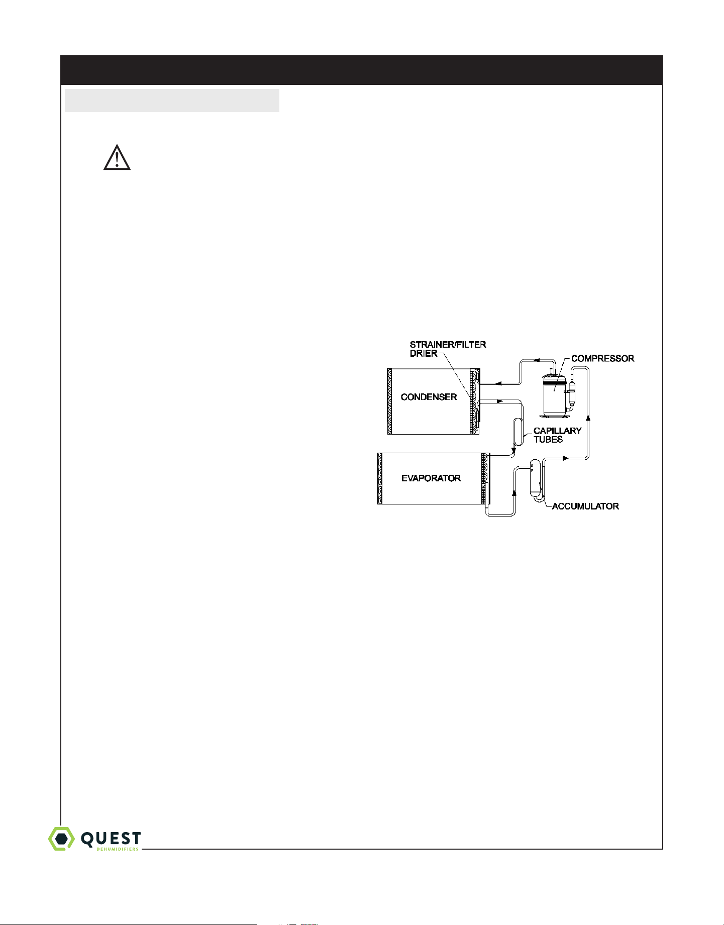
10.1 Technical Description
The Quest 70 uses a refrigeration system similar to an air conditioner’s to remove heat and moisture from incoming
air, and add heat to the air that is discharged. Hot, high-pressure refrigerant gas is routed from the compressor to the
condenser coil (See Figure 1). The refrigerant is cooled and condensed by giving up its heat to the air that is about to
be discharged from the unit. The refrigerant liquid then passes through a strainer and capillary tubing which causes
the refrigerant pressure and temperature to drop. It next enters the evaporator coil where it absorbs heat from the
incoming air and evaporates. The evaporator operates in a flooded condition, which means that all the evaporator tubes
contain liquid refrigerant during normal operation. A flooded evaporator should maintain nearly constant pressure and
temperature across the entire coil, from inlet to outlet.
The mixture of gas and liquid refrigerant enter the
accumulator after leaving the evaporator coil. The
accumulator prevents any liquid refrigerant from reaching
the compressor. The compressor evacuates the cool
refrigerant gas from the accumulator and compresses it to a
high pressure and temperature.
10.2 Troubleshooting
Neither fan nor compressor running. Dehumidification is
being called for. No fan call.
1. Unit unplugged or no power to outlet.
2. Humidity control set too high.
3. Loose connection in internal or control wiring.
4. Defective Compressor relay.
5. Defective control transformer.
Compressor is not running. Dehumidification is being called for. No fan call.
1. Defective compressor run capacitor.
2. Loose connection in compressor circuit.
3. Defective compressor overload.
4. Defective compressor.
5. Defrost thermostat open.
Compressor cycles on and o. Dehumidification is being called for. No fan call
1. Low ambient temperature and/or humidity causing unit to cycle through defrost mode.
2. Defective compressor overload (Sec. 7.6A).
3. Defective compressor (Sec. 7.6).
4. Defrost thermostat defective (Sec. 7.8).
5. Dirty air filter(s) or air flow restricted.
Refrigeration System of Quest 70
FOR HVAC INSTALLER ONLY

Quest 70 Installation, Operation and Maintenance Instructions
17
1-877-420-1330
www.QuestHydro.com
info@QuestHydro.com
Fan is not running. Dehumidification or fan is being called for
1. Loose connection in fan circuit.
2. Obstruction prevents fan impeller rotation.
3. Defective fan.
4. Defective fan relay.
Low dehumidification capacity (evaporator is frosted continuously). Dehumidification is being called for
1. Defrost thermostat defective.
2. Low refrigerant charge
3. Dirty air filter(s) or air flow restricted.
4. Excessively restrictive ducting connected to unit.
No ventilation. Ventilation is being called for.
1. Loose connection in ventilation control circuit
2. Loose connection in damper power circuit.
3. Defective fresh air damper.
Unit removes some water, but not as much as expected.
1. Air temperature and/or humidity have dropped.
2. Humidity meter and or thermometer used are
out of calibration.
3. Unit has entered defrost cycle.
4. Air filter dirty.
5. Defective defrost thermostat.
6. Low refrigerant charge.
7. Air leak such as loose cover or ducting leaks.
8. Defective compressor.
9. Restrictive ducting.
10.Optional Condensate Pump Safety Switch open.
Unit Test to determine problem:
1. Detach field control wiring connections from main unit.
2. Connect the 24V and FAN terminals from the main unit together; only the fan should run. Disconnect the
terminals.
3. Connect the 24V and DEHU terminals from the main unit together; the compressor and fan should run.
4. If these tests work, the main unit is working properly. You should check the control panel and field control wiring for
problems next.
5. Remove the control panel from the mounting box and detach it from the field installed control wiring. Connect the
DEHU, COM and FAN terminals from the control panel directly to the corresponding terminals on the main unit.
Leave the violet, white and red wires disconnected!
6. Turn on the fan switch; the fan should run. Turn o the fan switch.
7. Turn on the humidity control; the compressor and fan should run.
8. If these tests work, the problem is most likely in the field control wiring.
10.3 Refrigerant Charging
If the refrigerant charge is lost due to service or a leak, a new charge must be accurately weighed in. If any of the old
charge is left in the system, it must be recovered before weighing in the new charge. Refer to the unit nameplate for the
correct charge weight and refrigerant type.
FOR HVAC INSTALLER ONLY

Quest 70 Installation, Operation and Maintenance Instructions
18
1-877-420-1330
www.QuestHydro.com
info@QuestHydro.com
10.4 Compressor/Capacitor Replacement
This compressor is equipped with a two terminal external overload and a run capacitor, but no start capacitor or relay.
CAUTION
CAUTION-ELECTRICAL SHOCK HAZARD: Electrical power must be present to perform some tests. These tests
should be performed by a qualified service person.
10.5 Electric Ventilation Damper
The electric ventilation damper is controlled by the ventilation timer. The damper will open when the ventilation timer
is activated to allow fresh air into the structure through the fresh air inlet duct. The electric ventilation damper will
remain closed when the ventilation timer is not activated to prevent over-ventilating the structure when the unit is
dehumidifying or recirculating the indoor air. The electric ventilation timer operates on 24 Vac from the control circuit.
DO NOT connect high voltage to the damper motor or damage to the motor may result. DO NOT force the blade of
the damper by hand or damage to the damper motor may result.
The damper opens in one direction only. The damper rotates very slowly, allow sucient time for the damper to cycle.
The damper will take approximately one minute to cycle from closed to open or from open to closed.
If the electric ventilation damper fails to operate:
1. Check that the wiring is correct and that voltage is present at the damper motor.
2. Check for any obstruction inside the damper. If the electric ventilation damper fails to operate after performing
these checks, it must be replaced.
FOR HVAC INSTALLER ONLY

Quest 70 Installation, Operation and Maintenance Instructions
19
1-877-420-1330
www.QuestHydro.com
info@QuestHydro.com
Quest 70 Installation, Operation and Maintenance Instructions
Quest 70 Installation, Operation and Maintenance Instructions
Quest 70 Dehumidifier Limited Warranty
WARRANTOR:
Therma-Stor LLC
4201 Lien Rd
Madison, WI 53704
Telephone: 1-800-533-7533
WHO IS COVERED: This warranty extends only to the original residential end-user of the Quest 70 dehumidifier, and may not be
assigned or transferred.
FIRST YEAR WARRANTY: Therma-Stor LLC warrants that, for one (1) year after date of original purchase the Quest 70
Dehumidifier will operate free from any defects in materials and workmanship. Therma-Stor LLC’s exclusive obligation under this warranty
will be to supply, without charge, a replacement for the dehumidifier which is found to be defective within a one (1) year period from date of
purchase and which is returned not later than thirty (30) days after said one (1) year period to Therma-Stor LLC, Madison, WI together with
proof of purchase of the dehumidifier.
SECOND THROUGH FIFTH YEAR WARRANTY: Therma-Stor LLC further warrants that for a period of five (5) years,
the condenser, evaporator, and compressor of the Quest 70 dehumidifier will operate free of any defects in material or workmanship, or
Therma-Stor LLC, at its option, will repair or replace the defective part(s), provided that all labor and transportation charges for the part(s)
shall be borne by the end-user.
END-USER RESPONSIBILITIES: If warranty service is to be performed on the Quest 70, a technician authorized by Therma-Stor
LLC must perform such service. If the End-user is unable to locate or obtain warranty service from an authorized technician, he should call
Therma-Stor LLC at the above number and ask for the Service Department, which will then arrange for covered warranty service. Warranty
service will be performed during normal working hours.
The End-user must present proof of purchase (lease) upon request, by use of the warranty card, receipt, invoice or other reasonable and
reliable means. The end-user is responsible for normal care. This warranty only applies to residential applications, and is void if the Quest
70 Dehumidifier is used in commercial and/or industrial applications including but not limited to water treatment facilities and industrial
process applications. This warranty is void if the Quest 70 is used in any swimming pool application. This warranty does not cover any defect,
malfunction, etc. resulting from misuse, abuse, lack of normal care, corrosion, freezing, flooding, tampering, modification, unauthorized or
improper repair or installation, accident, acts of nature or any other cause beyond Therma-Stor LLC’s reasonable control.
LIMITATIONS AND EXCLUSIONS: If any Quest 70 Dehumidifier part is repaired or replaced, the new part shall be warranted for
only the remainder of the original warranty period applicable thereto (but all warranty periods will be extended by the period of time, if any,
that the Quest 70 Dehumidifier is out of service while awaiting covered warranty service).
UPON THE EXPIRATION OF THE WRITTEN WARRANTY APPLICABLE TO THE Quest 70 DEHUMIDIFIER OR ANY
PART THEREOF, ALL OTHER WARRANTIES IMPLIED BY LAW, INCLUDING MERCHANTABILITY AND FITNESS
FOR A PARTICULAR PURPOSE, SHALL ALSO EXPIRE. ALL WARRANTIES MADE BY THERMA-STOR LLC ARE SET
FORTH HEREIN, AND NO CLAIM MAY BE MADE AGAINST THERMA-STOR LLC BASED ON ANY ORAL WARRANTY.
IN NO EVENT SHALL THERMA-STOR LLC, IN CONNECTION WITH THE SALE, INSTALLATION, USE, REPAIR OR
REPLACEMENT OF ANY SANTA FE DEHUMIDIFIER OR PART THEREOF BE LIABLE UNDER ANY LEGAL THEORY
FOR ANY SPECIAL, INDIRECT OR CONSEQUENTIAL DAMAGES INCLUDING WITHOUT LIMITATION WATER
DAMAGE (THE END-USER SHOULD TAKE PRECAUTIONS AGAINST SAME), LOST PROFITS, DELAY, OR LOSS OF
USE OR DAMAGE TO ANY REAL OR PERSONAL PROPERTY.
Some states do not allow limitations on how long an implied warranty lasts, and some do not allow the exclusion or limitation of incidental or
consequential damages, so one or both of these limitation may not apply to you.
LEGAL RIGHTS: This warranty gives you specific legal rights, and you may also have other rights which vary from
state to state.