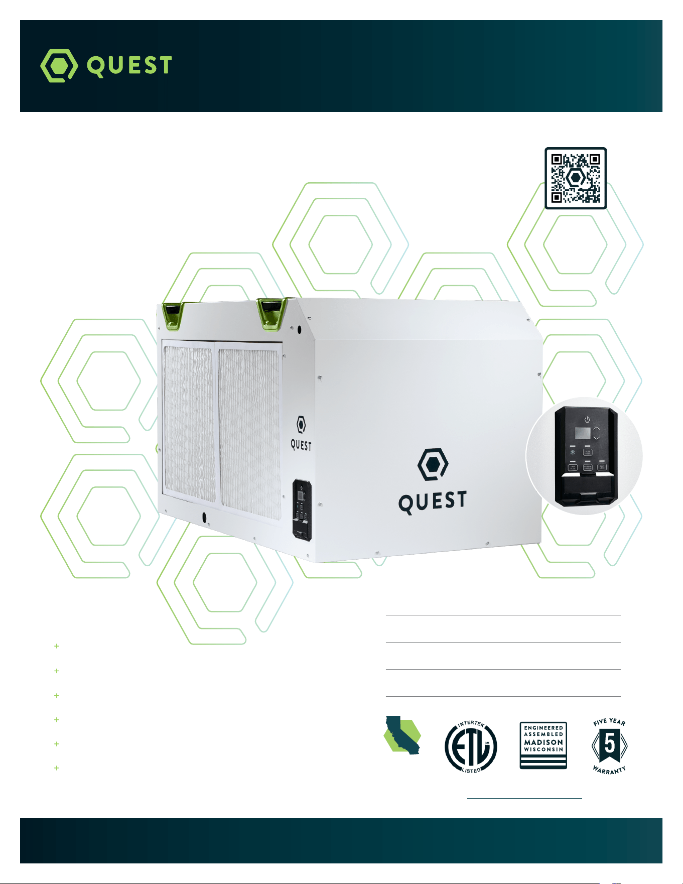
INSTALLATION, OPERATION, AND
MAINTENANCE INSTRUCTIONS
QUEST
506
QUESTCLIMATE.COM / (877) 420-1330
Patents: thermastor.com/patents
Model Number #4046300 / 4046310
Serial Number
Install Date
Sold By
TS-2041 11/24 REV B
230V & 277V Options
Industry-Leading Efficiency
Patented M-CoRR
TM
Technology
Superior MERV-13 Air Filtration
Auto-Restart After Power Outages
Lower Temperature Performance
For complete product
information, scan here:
CALIFORNIA
TITLE 24 COMPLIANT

2
QUEST 506 INSTALLATION, OPERATION, AND MAINTENANCE INSTRUCTIONS
QUESTCLIMATE.COM(877) 420-1330
TABLE OF CONTENTS
Safety Precautions ............................................................. 1
1. Intended Application ....................................................2
2. Registrations .................................................................2
3. Specifications ................................................................ 3
4. Installation .....................................................................3
4.1 Location ...................................................................3
4.2 Electrical Requirements .....................................3
4.3 Condensate Water Removal ...............................4
4.4 Hanging .................................................................5
4.5 Ducting Guidelines ............................................. 6
5. Controls..... .....................................................................7
5.1 Onboard Control .....................................................7
5.2 External Control Options ....................................9
5.3 Wiring Controllers ............................................ 10
5.4 Daisy Chain .......................................................... 10
6. Maintenance ................................................................. 11
6.1 Standard Air Filter ............................................... 11
7. Service........ ................................................................... 11
7.1 Warranty ................................................................ 11
7.2 Technical Description .......................................... 11
7.3 Service Personnel ............................................... 11
7.4 Checks to Electrical devices ............................ 12
7.5 Repair to Sealed Components ......................... 13
7.6 Repair to Intrinsically Safe Components........ 13
7.7 Detection of Flammable Refrigerants ............ 13
7.8 Refrigerant Removal & Evacuation ....... 14
7.9 Charging Procedures ................................ 14
7.10 Troubleshooting ....................................... 14
8. Decommissioning............................................... 16
Wiring Diagram........................................................ 20
Service Parts List ................................................... 18
Optional Parts List ................................................. 18
Warranty .................................................................. 22
4201 Lien Rd. Madison, WI 53704 | 1-877-420-1330
Thermastor.com | QuestClimate.com
© 2024 Therma-Stor LLC
1
QUEST 506 INSTALLATION, OPERATION, AND MAINTENANCE INSTRUCTIONS
QUESTCLIMATE.COM(877) 420-1330
SAFETY PRECAUTIONS
Read the installation, operation, and maintenance instructions carefully before installing and operating
this device. Proper adherence to these instructions is essential to obtain maximum benefit from your
Quest dehumidifier.
READ AND SAVE THESE INSTRUCTIONS
» The device is designed to be installed INDOORS IN A SPACE THAT IS PROTECTED FROM
RAIN AND FLOODING.
» Install the unit with space to access the back or side panels for maintenance and service.
DO NOT INSTALL UNIT WITH THE SERVICE PANELS INACCESSIBLE.
» Avoid directing the discharge air at people, or over the water in pool areas.
» If used near a pool, spa, or water; be certain there is NO chance the unit could fall into
the water, be splashed and that it is plugged into an outlet that is a GROUND FAULT
INTERRUPT protected circuit.
» DO NOT use the device as a bench or table.
» DO NOT place the device directly on structural members. Provide vibration isolation in
order to minimize operational vibration and/or noise.
» A drain pan MUST be placed under the unit if installed above a living area or above an
area where water leakage could cause damage.
» Never operate a unit with a damaged power cord. If the power cord is damaged it must
be replaced by the manufacturer, its service agent, or similarly qualified person in order
to avoid a hazard.
» Make all electrical connections in accordance with the current edition of the NEC ANSI/
NFPA 70 and any national and local codes or ordinances that may apply.
» Maintain a minimum 3ft. (1m) clearance to avoid obstructing the air return and supply.
» This appliance is not intended for use by persons (including children) with reduced
physical, sensory or mental capabilities, or lack of experience and knowledge, unless they
have been given supervision or instruction concerning use of the appliance by a person
responsible for their safety. Children should be supervised to ensure that they do not
play with the appliance.
» Not intended for use at altitudes over 6500 ft (2000M).
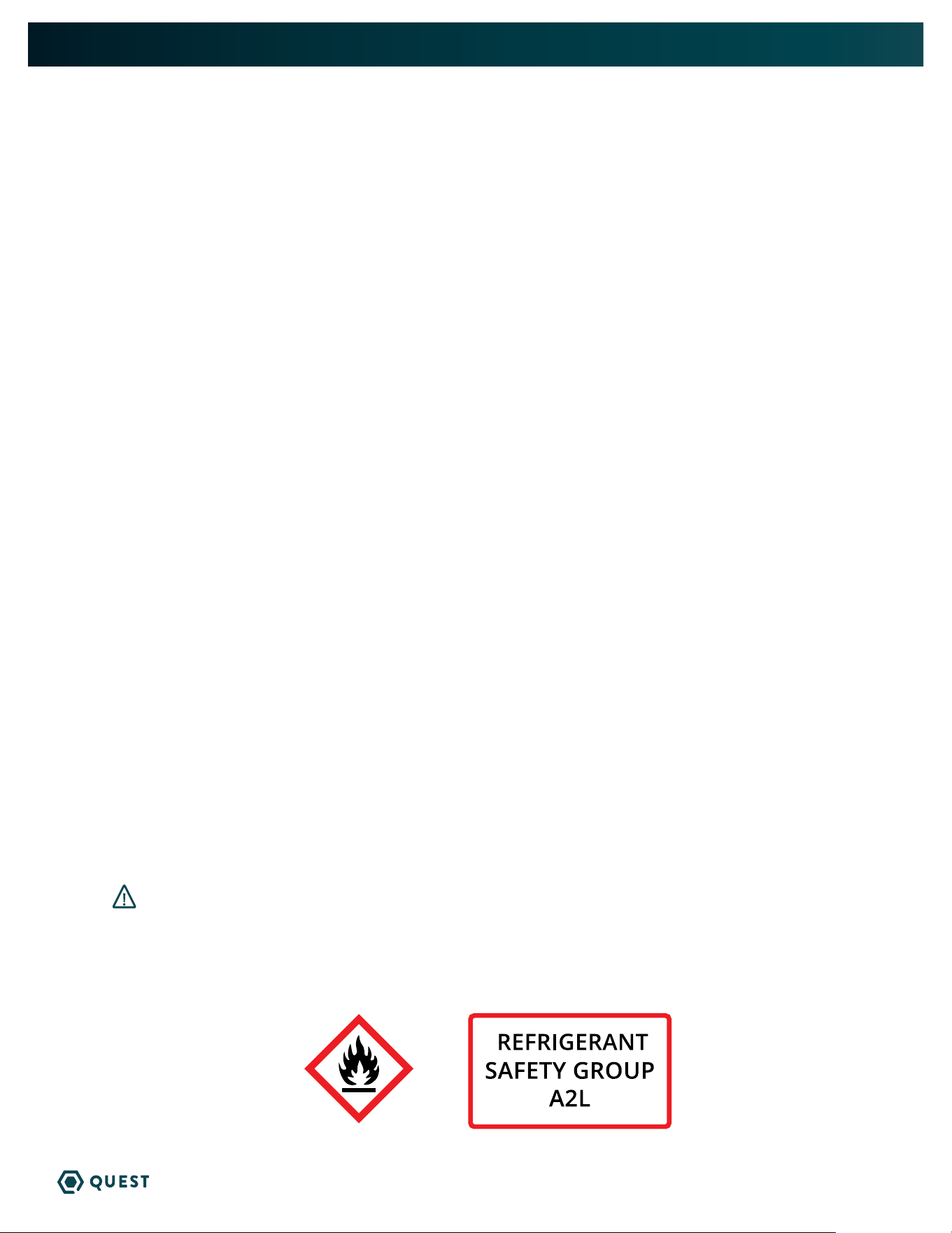
Do not use means to accelerate the defrosting process or to clean,
other than those recommended by the manufacturer.
The appliance shall be stored in a room without continuously operating ignition sources
(for example: open flames, an operating gas appliance, or an operating electric heater.
Do not pierce or burn. Be aware that refrigerants may not contain an odor.
WARNING
2
QUEST 506 INSTALLATION, OPERATION, AND MAINTENANCE INSTRUCTIONS
QUESTCLIMATE.COM(877) 420-1330
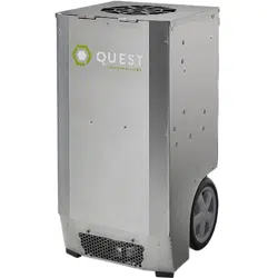
1. INTENDED APPLICATION FOR QUEST 506
The Quest 506 Dehumidifier is designed to operate in temperatures between 56 F and 95 F.
In order to efficiently control humidity levels, the area in which the dehumidifier is to be operated must
be free of water intrusion or excessive fresh (outside) air infiltration. Before installing the Quest 506
Dehumidifier, water intrusion and air infiltration problems should be addressed or noted in calculations.
2. REGISTRATIONS
The Quest 506 Dehumidifier units conform to unified standards: UL 60335-2-40, CSA 22.2 # 60335-2-
40:2012 Ed. 1+4. Patent: thermastor.com/patents
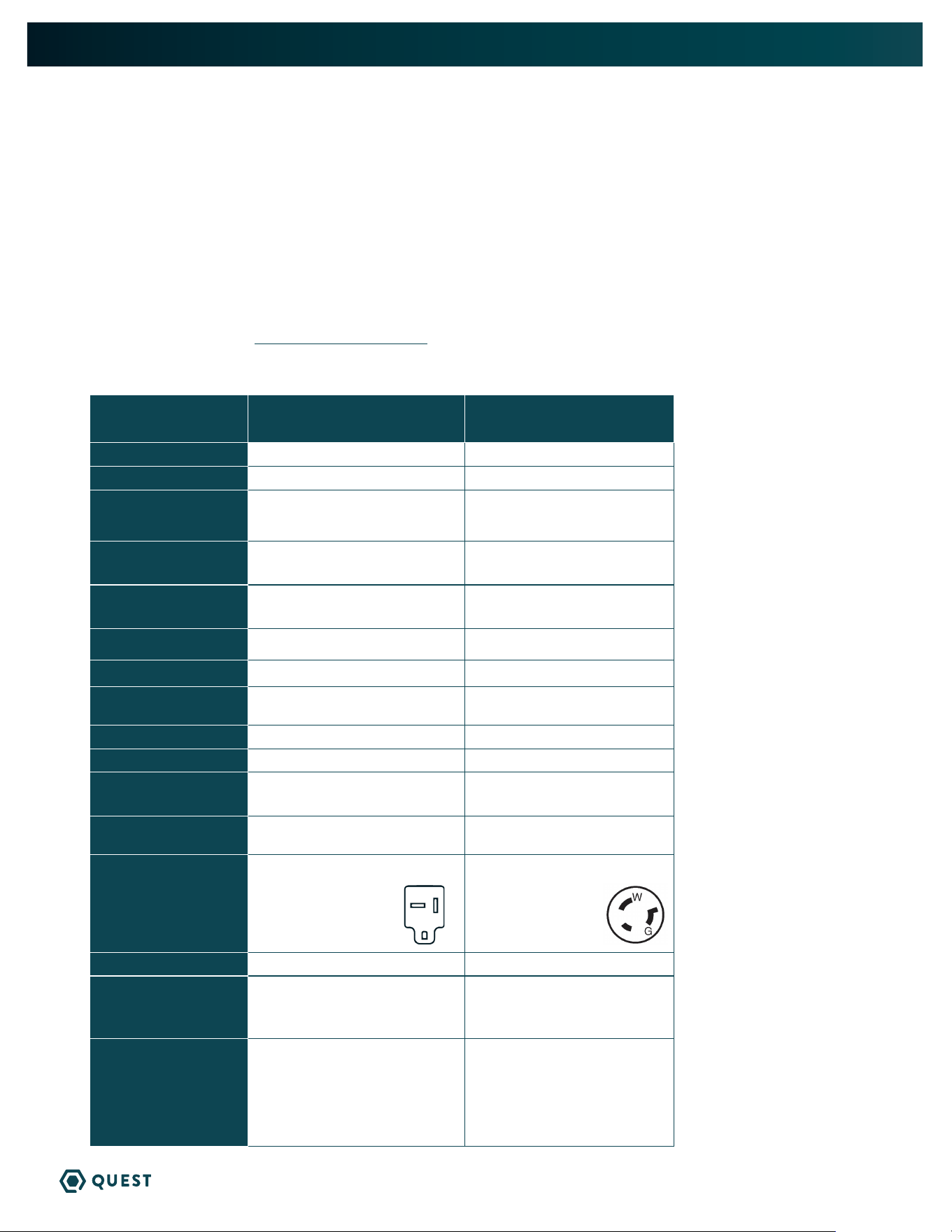
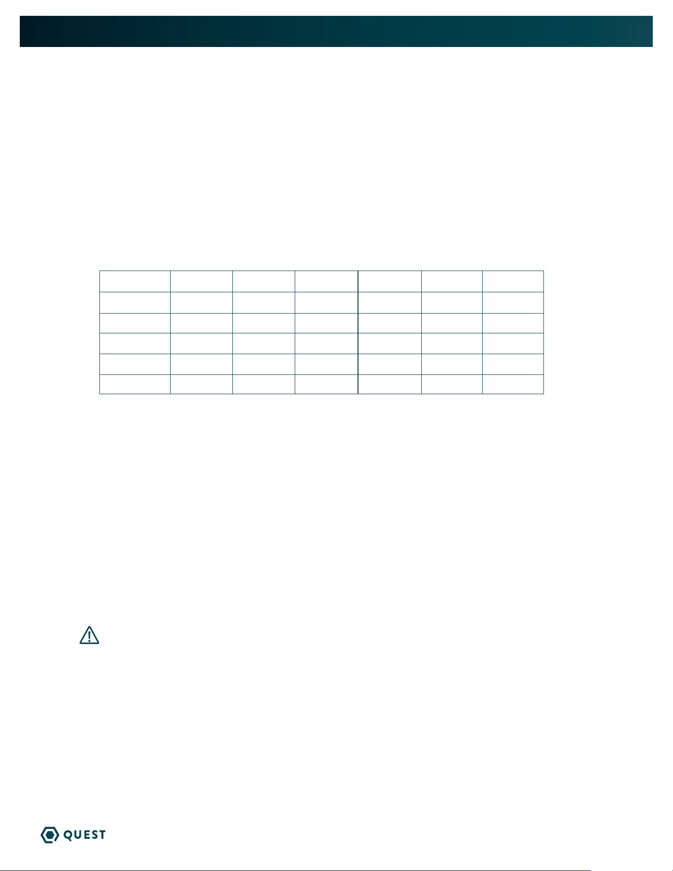
3. SPECIFICATIONS @ 80°F/60% RH
UNIT
QUEST 506
4046300
QUEST 506 277V
4046310
CFM:
1150 @ 0.0” WG 1150 @ 0.0” WG
POWER:
2250 Watts 2250 Watts
SUPPLY VOLTAGE:
208-230 VAC
1 Phase - 60 Hz
277 VAC
1 Phase - 60 Hz
CURRENT DRAW:
9.9A @ 230V
10.9 @208V
8.2A
RATED CURRENT DRAW
(AMPS): (104 F | 36%)
15.2A @208V
13.8 @230V
15.2A
MCA *
20A 15A
MOP *
25A 25A
RECOMMENDED
BREAKER SIZE:
25A 25A
ENERGY FACTOR:
4.4 L/kWh 4.4 L/kWh
OPERATING TEMP:
56 F Min – 95 F Max 56 F Min – 95 F Max
WATER REMOVAL:
EFFICIENCY:
500 Pints/Day
9.2 Pints/kWh
500 Pints/Day
9.2 Pints/kWh
AIR FILTER (MERV-13):
QTY 2
Size: 18” x 20” x 2” Size: 18” x 20” x 2”
POWER CORD:
PLUG:
12/3, SJTW, 20A (6’)
NEMA 6-20P
12/3, SJTW, 20A (6’)
NEMA L7-20P
DRAIN CONNECTION:
3/4” Threaded NPT 3/4” Threaded NPT
REFRIGERANT TYPE:
REFRIGERANT
AMOUNT:
R454B
3 lb 14 oz
R454B
3 lb 14 oz
DIMENSIONS:
LENGTH:
WIDTH:
HEIGHT:
WEIGHT:
Unit Shipping
44.7” 47”
29.0” 33”
27.4” 28”
275 lb 335 lb
Unit Shipping
44.7” 47”
29.0” 33”
27.4” 28”
275 lb 335 lb
* MCA = Minimum Circuit Ampacity
This number provides a qualified
electrician with the information needed
to determine the minimum wire size
used in the circuit that feeds a single
dehumidifier.
* MOP = Maximum Overcurrent
Protection
This number provides a qualified
electrician with the value of the
maximum size circuit breaker that may
be used to protect the circuit that feeds
a dehumidifier.
NOTES:
Specifications are subject
to change without notice.
3
QUEST 506 INSTALLATION, OPERATION, AND MAINTENANCE INSTRUCTIONS
QUESTCLIMATE.COM(877) 420-1330
4. INSTALLATION
4.1 LOCATION
The Quest 506 Dehumidifier can be installed in a variety of locations to meet the owner’s needs as listed
below. In all cases keep the following cautions in mind:
» It is designed to be installed INDOORS IN A SPACE THAT IS PROTECTED FROM RAIN AND
FLOODING.
» Install the unit with space to access side panel for maintenance and service. DO NOT INSTALL UNIT
WITH ACCESS PANEL INACCESSIBLE.
» The minimum floor area of the room shall be 28m
2
(square meters) at sea level. To establish
minimum room area at different altitude, multiply 63.4m
2
by Altitude Adjustment Factor. See below.
H
alt
m
0 200 400 600 800 1000
H
alt
ft
0 656 1312 1969 2625 3281
Factor
1 1 1 1 1.02 1.05
H
alt
m
1000 1200 1400 1600 1800 2000
H
alt
ft
3281 3937 4593 5249 5906 6562
Factor
1.05 1.07 1.1 1.12 1.15 1.18
» Keep any required ventilation openings clear of obstruction;
» Ducts connected to the dehumidifier shall not contain a POTENTIAL IGNITION SOURCE;
» Supply and return air shall be directly ducted to the space. Open areas such as false ceilings shall
not be used as a return air duct;
Unventilated Areas
» Unventilated Areas where the Quest 506 is installed or stored need to be so constructed that should
any refrigerant leak, it will not stagnate so as to create a fire or explosion hazard.
» The Quest 506 shall not be stored or ducted into one or multiple rooms with continuously operating
open flames (for example an operating gas appliance) or other POTENTIAL IGNITION SOURCES (for
example an operating electric heater, hot surfaces). A flame-producing device may be installed in
the same space if the device is provided with an effective flame arrest.
4.2 ELECTRICAL REQUIREMENTS
WARNING! Electrical shock hazard: Electrical power must be present for some
test. These test should be performed by a qualified service person.
The Quest 506 208/230v dehumidifier plugs into NEMA 6-20R rated receptacle. The Quest 506 277v
dehumidifer plugs into a NEMA L7-20P rated receptacle. The amp draws are listed on Section 3 of this
manual. Connecting to electrical power must comply with all national, state and local electrical codes. A
ground fault interrupter protected circuit is recommended. This unit shall not be used with an extension
cord.
4
QUEST 506 INSTALLATION, OPERATION, AND MAINTENANCE INSTRUCTIONS
QUESTCLIMATE.COM(877) 420-1330
Low Voltage Connections
Install the external control in a central area of the structure where it will sense the relative humidity
accurately. Do not install the control sensor where it may not accurately measure the relative humidity
such as near HVAC supply registers, near exterior doors or near pool or spas. The installer must supply
the wiring between the dehumidifier and the external control. Be sure to safely route the control
wiring to prevent damage during installation. Be careful not to cross the wires when connecting the
dehumidifier and the external control.
The controls of the dehumidifier are powered by a low voltage circuit (24VAC) and must NEVER contact or
be connected to a high voltage circuit. The control terminals are labeled to prevent confusion.
WARNING! Damaged power cords can only be replaced with one by the unit manufacturer.
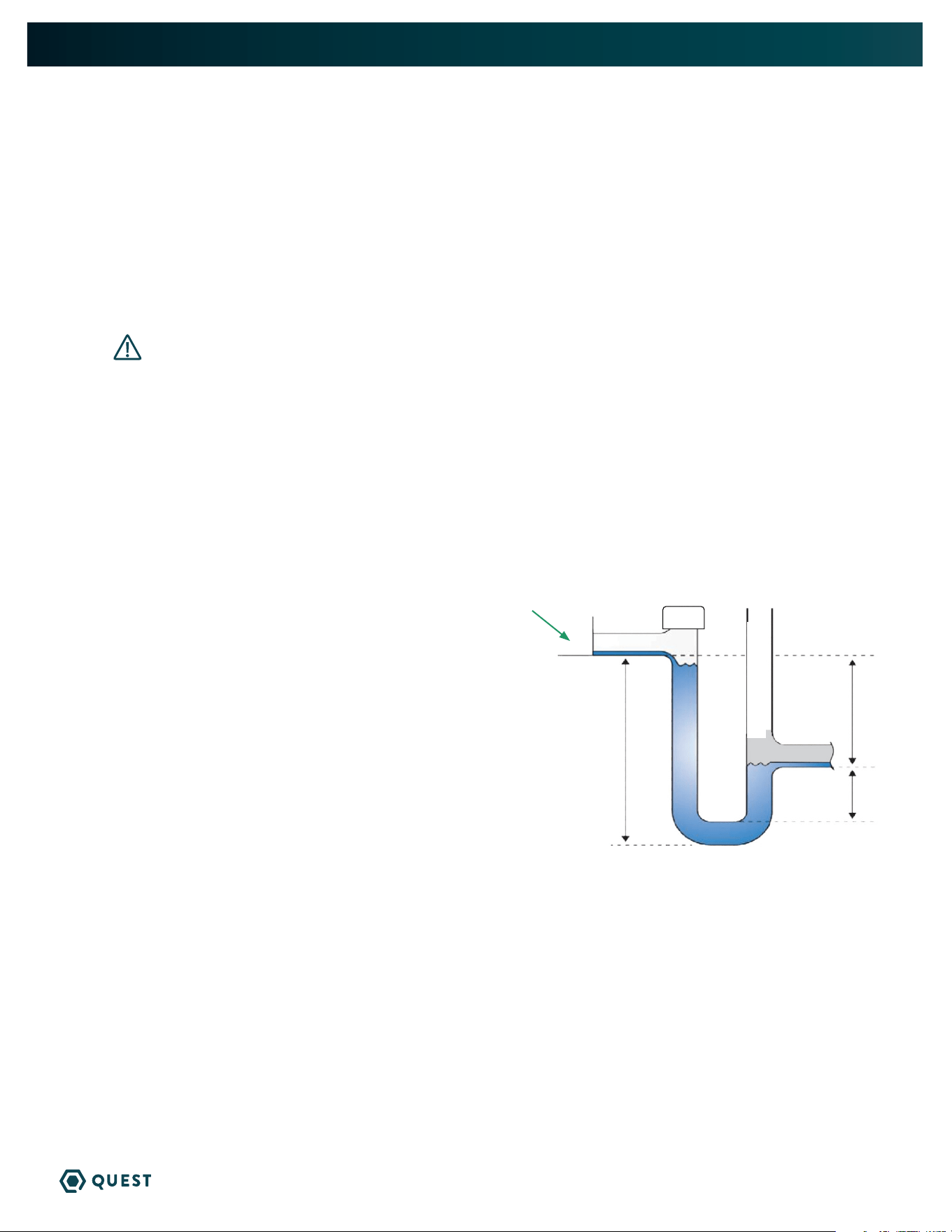
4.3 CONDENSATE WATER REMOVAL
Condensate drains by gravity via the drain port. A drain trap is required to prevent backflow of water.
Use 3/4” male NPT PVC pipe and diagram below. An optional condensate pump kit may be installed if a
lift is required to dispose of the condensate. See optional parts list for information on the kit.
FOLLOW DIAGRAM:
» Level within 2°
Vent:
» Place vent after the trap.
» Vent should be open.
» Height of vent should be higher than drain outlet.
Cap:
» A clean out can be placed before trap but must be
sealed with a cap.
Drain Line:
» Drain line should go in a downward slope to the drain.
» 1/4” drop per foot.
Drain Trap Configuration
VENT OPEN
CAP
2”
6.75”
4”
3/4” drain port
5
QUEST 506 INSTALLATION, OPERATION, AND MAINTENANCE INSTRUCTIONS
QUESTCLIMATE.COM(877) 420-1330
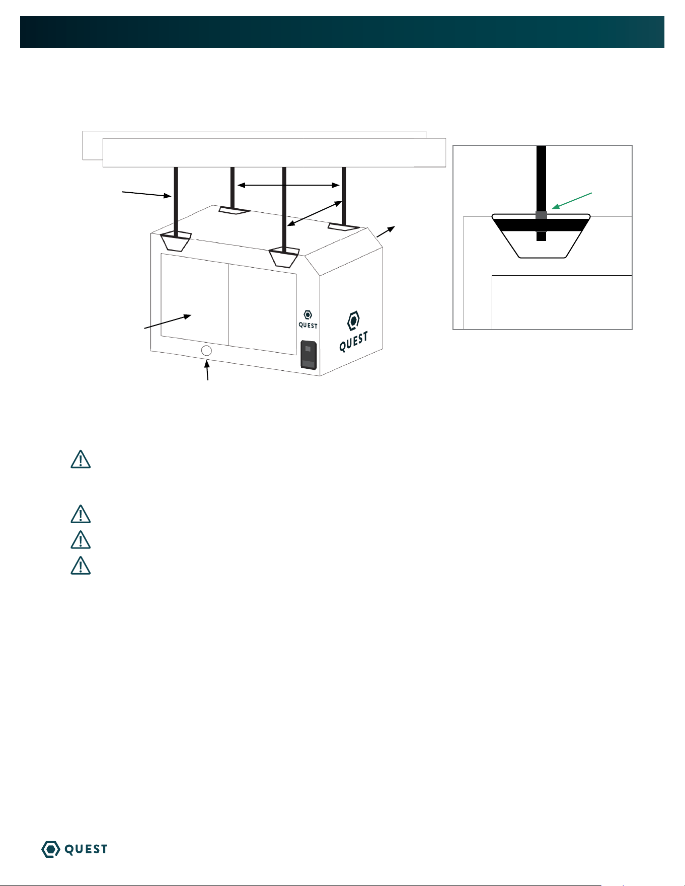
28.95”
27.25”
3/8” threaded rod
Intake Air
Treated Air
3/8” Jam Nuts
4.4 HANGING DIAGRAM
WARNING! Check the supporting structure to be used to verify that it has sufficient load
carrying capacity to support the weight of the unit. Suspend the unit only from the threaded nut
retainers. Do NOT suspend from the cabinet.
CAUTION! Recommended maximum hanger rod is 6 feet (1.8m).
WARNING! Hanging installation must meet all state and local codes.
WARNING! Installation should be done by a qualified agency in accordance with these
instructions. The qualified service agency installing this high efficiency refrigeration system is
responsible for the installation.
PARTS NEEDED:
4 pieces 3/8” threaded rod (not included)
4 - 3/8” threaded jam nuts (not included)
3/4” drain port
6
QUEST 506 INSTALLATION, OPERATION, AND MAINTENANCE INSTRUCTIONS
QUESTCLIMATE.COM(877) 420-1330
4.5 DUCTING GUIDELINES
CAUTION! Quest 506 is intended for use in statics under .25”WG.
• Ducting either the intake or exhaust use a minimum of two 15” diameter round ducts minimum.
• Grills or diffusers on the duct ends must not excessively restrict airflow.
• Effective dehumidification may require ducting to be branched to isolated or stagnant flow areas.
Be sure to use appropriate size duct branches to maintain proper feed throughout the ducting
system.
• System control should be placed remotely from the dehumidifier in a central location.
• Intake and exhaust ducting should have a minimum of 4 feet from the unit before any turns.
CAUTION! Do not connect with a static pressure greater than +.25”wg. Contact
technical support for additional details.
Optional duct kits are available from the factory: Exhaust Kit #4044431 and Intake Kit #4044430.
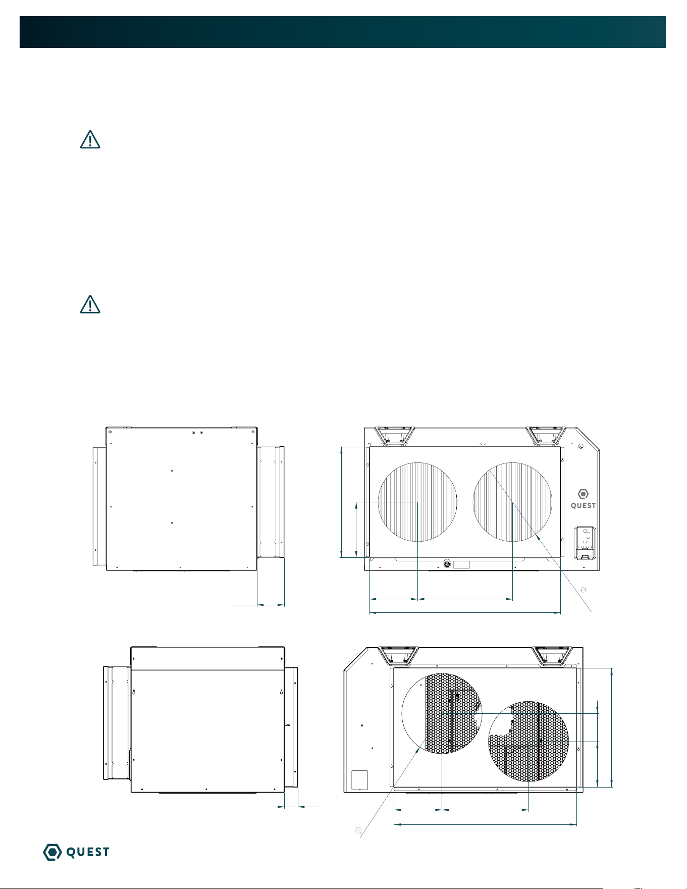
See figures below for plenum dimensions and duct diameters. Alternatively, licensed contractors
can fabricate duct plenums and reference figures below for safe fastener mounting points.
6 SERIES INTAKE DUCT LOCATION
6 SERIES SUPPLY DUCT LOCATION
21.00”
36.26”
9.13” 18.00”
10.50”
2X
15.00”
5.18”
34.10”
22.22”
8.96”16.18”
8.50”5.22”
2X
15.00”
2.50”
7
QUEST 506 INSTALLATION, OPERATION, AND MAINTENANCE INSTRUCTIONS
QUESTCLIMATE.COM(877) 420-1330
5. CONTROL OPTIONS
The Quest 506 Dehumidifier may be controlled by onboard controls or an external remote humidistat
through a 24v terminal block. External control NOT provided.
5.1 ONBOARD CONTROL
Off Mode: Fan, Compressor, Display, and all LEDS are off
Turn Unit ON: Press the Power button
On Mode: Display is on and shows the RH set point (initial set point: 55% RH)
To Change Set Point:
» Press the up or down arrow once, the 2-digit display will begin to blink.
» Adjust to desired relative humidity. Each push of the button will change the SP 1% RH.
» After 6 seconds without a button being pushed, the number showing will become the
new set point
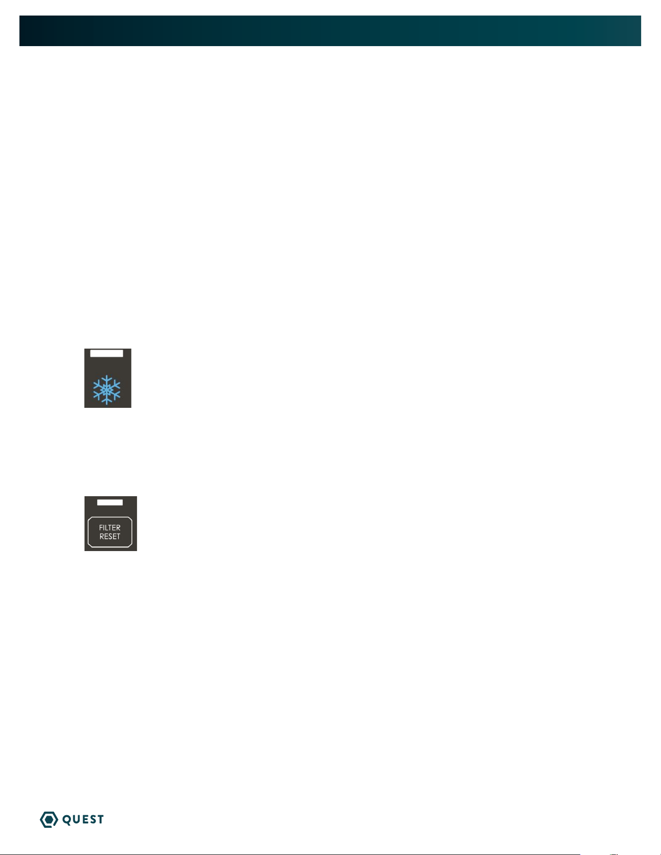
DEFROST LIGHT
» The light over the snowflake will light up when defrost is occurring (ice is detected on
coils). The fan will be on, and the compressor will be off during defrost.
FILTER RESET
» Filter reset button will light up after the fan has been running for 2,000 hours, or if
the pressure switch detects excessive pressure build-up indicating that the filter must be changed.
» After changing the filter, press and hold the filter reset button to reset the 2,000-hour timer. Light
flashes while button is held.
8
QUEST 506 INSTALLATION, OPERATION, AND MAINTENANCE INSTRUCTIONS
QUESTCLIMATE.COM(877) 420-1330
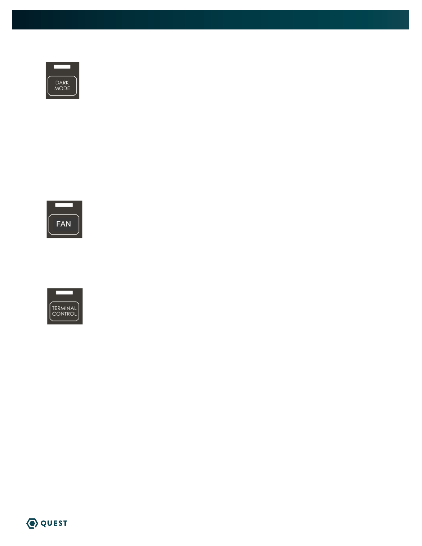
DARK MODE
» Press the Dark Mode button to activate Dark Mode.
» Once Dark Mode is activated, lights will remain on for 20 seconds before the unit’s hygrostat will go
dark. Dark Mode light will flash for 3 seconds before unit goes dark.
» Unit will temporarily leave dark mode when any button is pushed and will go dark 20 seconds after
the last button is pushed.
» To turn off Dark Mode, press the Dark Mode button and ensure light above Dark Mode button is off.
» This mode is for applications where the user would like the unit to operate without emitting any light.
FAN
Pressing the Fan button alternates the Fan running with the compressor and Fan always on. Make sure the
wire jumper on the low voltage terminal block is moved from FAN-to-24V COM to FAN-to-24VAC
TERMINAL CONTROL
» When the Terminal Control button is pressed, the display will show “tc”.
» The Terminal Control button is used to activate the “DEHUM” input on the terminal block.
(see section 5.3)
» This must be activated when an external control is used to control RH. When Terminal Control
is active, the internal RH sensor is disabled.
9
QUEST 506 INSTALLATION, OPERATION, AND MAINTENANCE INSTRUCTIONS
QUESTCLIMATE.COM(877) 420-1330
5.2 EXTERNAL CONTROL OPTIONS
A 24VAC signal is sent by the remote humidistat signals the fan or fan and compressor to actuate.
Quest offers two external control options:
» DEH 3000R
» Honeywell Humidistat
Other options: Any 24V signal to dehumidify, such as Trolmaster.
5.3 WIRING EXTERNAL CONTROL
The terminal block, low voltage circuit breaker, and onboard controls are located on the intake
side of the unit. Disconnect power while wiring the unit.
CAUTION! Low Voltage Hazard. Can cause equipment damage.
Disconnect power before beginning installation.
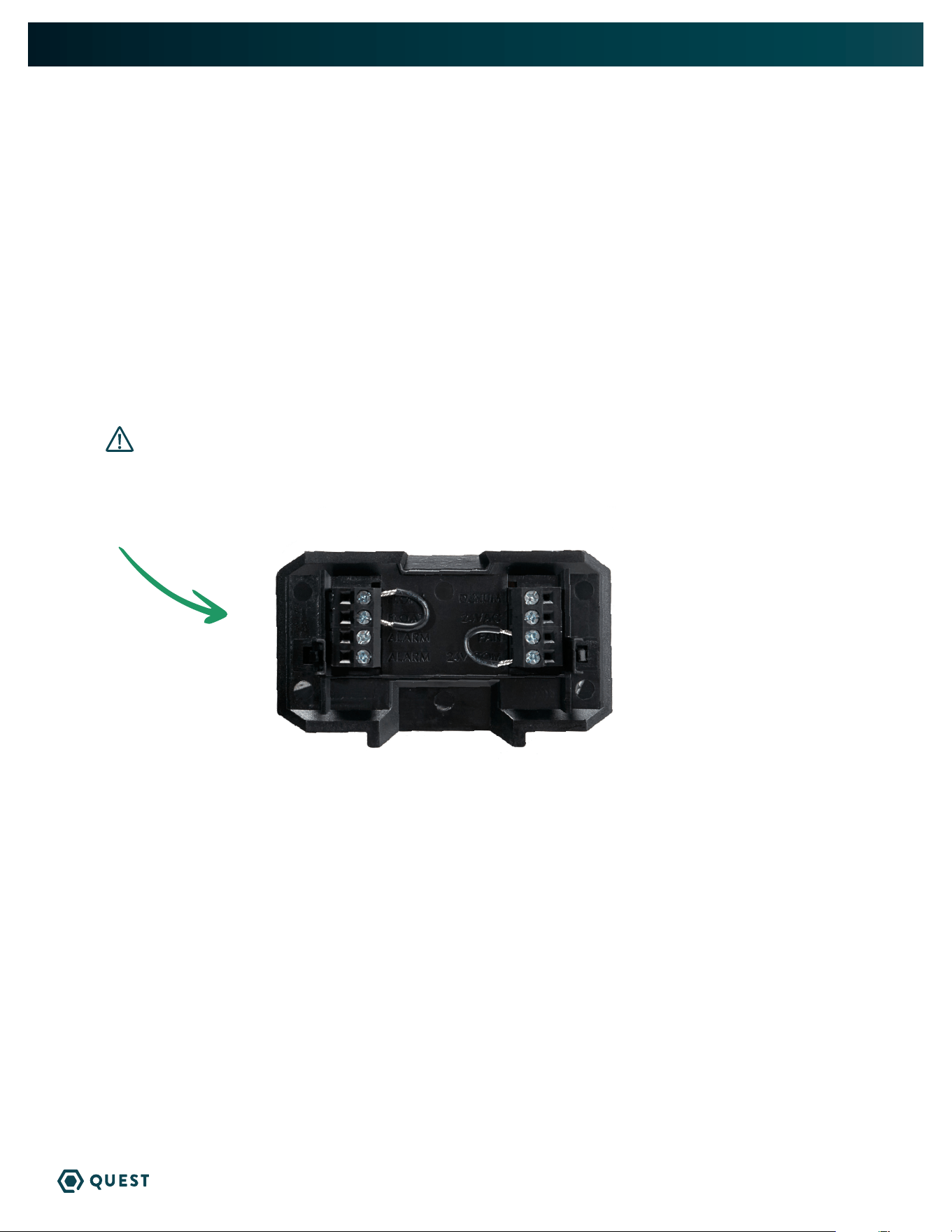
Remove the cover from the bottom of the user interface to expose the terminal block inputs and outputs.
QUEST 506 TERMINAL BLOCK CONTROL OPERATIONS:
DEHUM: Dehumidification (Fan and Compressor) Control Input.
24VAC: Transformer High Side Output to External Control.
Fan: Fan Control Input.
24V COM: 24VAC Power Transformer Neutral Side Output to External Control.
FLOAT: External Low Voltage Float Switch or Water Sensor Input (Use Normally Closed Switch).
FLOAT: External Low Voltage Float Switch or Water Sensor Input (Use Normally Closed Switch).
Alarm: Normally Closed Relay Output - Indicates when dehumidifier is in an alarm state.
Alarm: Normally Closed Relay Output - Indicates when dehumidifier is in an alarm state.
NOTE: Alarm terminals are used to interface with a remote alarm or building automation
system. The terminals switch when the unit has a malfunction and are factory set
to “normally closed” but can be changed to “normally open”.
10
QUEST 506 INSTALLATION, OPERATION, AND MAINTENANCE INSTRUCTIONS
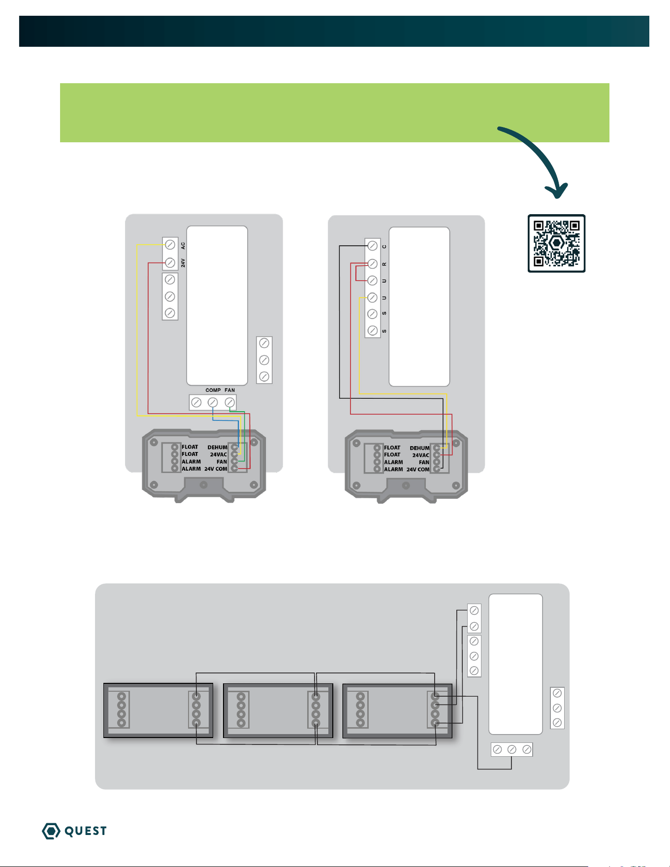
QUESTCLIMATE.COM(877) 420-1330
HONEYWELL HUMIDIPRO
WIRING DIAGRAM
QUEST DEH 3000R CONTROL
WIRING DIAGRAM
PN 4028531
PN 4041649
NOTE: 22ga wire needed for sensor.
To order a controller, contact your dealer, call 1-877-420-1330, or go to:
www.questclimate.com/product-category/accessories
24VAC
COMP FAN
QUEST DEH 3000R CONTROLLER
QUEST 506 -
UNIT#2
QUEST 506 -
UNIT#3
QUEST 506 -
UNIT#1
*NOTE - DO NOT WIRE IN “FAN” TERMINAL WITH THIS APPLICATION
ALARM
FLOAT
FLOAT
FAN
24V COM
ALARM
DEHUM
24VAC
ALARM
FLOAT
FLOAT
FAN
24V COM
ALARM
DEHUM
24VAC
ALARM
FLOAT
FLOAT
FAN
24V COM
ALARM
DEHUM
24VAC
5.4 DAISY CHAIN

11
QUEST 506 INSTALLATION, OPERATION, AND MAINTENANCE INSTRUCTIONS
QUESTCLIMATE.COM(877) 420-1330
6. MAINTENANCE
WARNING! Do not operate the unit without the filter or with a less effective filter.
The heat exchange coils inside the unit could become clogged and require disassembly to
clean. Filter non-compliance invalidates the product warranty.
6.1 STANDARD AIR FILTER
The Quest 506 Dehumidifier ships with a standard MERV 13 efficient pleated fabric filter. This filter
should be checked every six months. Operating the unit with a dirty filter will reduce dehumidifier
capacity and efficiency and may cause the compressor to cycle off and on unnecessarily on the defrost
control.
To access the air filter, the filter should be readily visible and can be removed by pulling it straight out of
the Quest 506 Dehumidifier.
We recommend changing the filter every 3-6 months, or in growing environments, at least with every
grow cycle.
7. SERVICE
WARNING! Servicing the Quest 506 with its high pressure refrigerant system and high
voltage circuitry presents a health hazard which could result in death, serious bodily injury,
and/or property damage. Only qualified service people should service this unit.
7.1 WARRANTY
A warranty certificate has been enclosed with this unit; read it before any repair is initiated. If a
warranty repair is required, call the factory first at 1-877-420-1330 for warranty claim authorization and
technical assistance.
7.2 TECHNICAL DESCRIPTION (NON STANDARD PATENTED)
The Quest 506 Dehumidifier uses a refrigeration system similar to an air conditioner’s to remove heat
and moisture from incoming air, and add heat to the air that is discharged.
Hot, high-pressure refrigerant gas is routed from the compressor to the condenser coil. The refrigerant
is cooled and condensed by giving up its heat to the air that is about to be discharged from the unit. The
refrigerant liquid then passes through a filter/drier and expansion drier which causes the refrigerant
pressure and temperature to drop. It next enters the evaporator coil where the cool refrigerant absorbs
heat from the incoming air and evaporates.
The compressor evacuates the cool refrigerant vapor from the evaporator and compresses it to a high
pressure and temperature to repeat the process.
7.3 SERVICE PERSONNEL
Only qualified HVAC or electrical contractors are allowed to conduct maintenance, service and/or
repair operations on Quest 506 machines. Examples include but are not limited to breaking into the
refrigerating circuit, opening of sealed components, and/or opening of ventilated enclosures.
Prior to beginning work on the Quest 506 machine, safety checks are necessary to ensure that the risk
of ignition is minimized.
» For repair to the REFRIGERATING SYSTEM, a qualified contractor should first establish a controlled
procedure so as to minimize the risk of a flammable gas or vapor being present while the work is
being performed.

12
QUEST 506 INSTALLATION, OPERATION, AND MAINTENANCE INSTRUCTIONS
QUESTCLIMATE.COM(877) 420-1330
» All maintenance staff and others working in the local area shall be instructed on the nature of work
being carried out. Work in confined spaces shall be avoided.
» The area shall be checked with an appropriate refrigerant detector prior to and during work, to
ensure the technician is aware of potentially toxic or flammable atmospheres. Ensure that the leak
detection equipment being used is suitable for use with all applicable refrigerants, i.e. non-sparking,
adequately sealed or intrinsically safe.
» If any hot work is to be conducted on the refrigerating equipment or any associated parts,
appropriate fire extinguishing equipment shall be available to hand. Have a dry powder or CO2 fire
extinguisher adjacent to the charging area
» No person carrying out work in relation to a REFRIGERATING SYSTEM which involves exposing
any pipe work shall use any sources of ignition in such a manner that it may lead to the risk of fire
or explosion. All possible ignition sources, including cigarette smoking, should be kept sufficiently
far away from the site of installation, repairing, removing and disposal, during which refrigerant
can possibly be released to the surrounding space. Prior to work taking place, the area around the
equipment is to be surveyed to make sure that there are no flammable hazards or ignition risks. “No
Smoking” signs shall be displayed.
» Ensure that the area is in the open or that it is adequately ventilated before breaking into the
system or conducting any hot work. A degree of ventilation shall continue during the period that the
work is carried out. The ventilation should safely disperse any released refrigerant and preferably
expel it externally into the atmosphere.
The following checks shall be applied to installations using FLAMMABLE REFRIGERANTS:
» Where electrical components are being changed, they shall be fit for the purpose and to the correct
specification. At all times Therma-Stor’s maintenance and service guidelines shall be followed. If in
doubt, consult Therma-Stor’s technical department for assistance.
» The actual REFRIGERANT CHARGE is in accordance with the room size within which the refrigerant
containing parts are installed.
» the ventilation machinery and outlets are operating adequately and are not obstructed.
» Marking to the equipment continues to be visible and legible. Markings and signs that are illegible
shall be corrected.
» Dehumidifiers are installed in a position where they are unlikely to be exposed to any substance
which may corrode refrigerant containing components, unless the components are constructed of
materials which are inherently resistant to being corroded or are suitably protected against being so
corroded.
7.4 CHECKS TO ELECTRICAL DEVICES
Repair and maintenance to electrical components shall include initial safety checks and component
inspection procedures. If a fault exists that could compromise safety, then no electrical supply shall be
connected to the circuit until it is satisfactorily dealt with. If the fault cannot be corrected immediately
but it is necessary to continue operation, an adequate temporary solution shall be used. This shall be
reported to the owner of the equipment so all parties are advised.
Initial safety checks shall include:
• that capacitors are discharged: this shall be done in a safe manner to avoid possibility of sparking.
• that no live electrical components and wiring are exposed while charging, recovering or purging the
system.
• that there is continuity of earth bonding.

13
QUEST 506 INSTALLATION, OPERATION, AND MAINTENANCE INSTRUCTIONS
QUESTCLIMATE.COM(877) 420-1330
7.5 REPAIRS TO SEALED COMPONENTS
» During repairs to sealed components, all electrical supplies shall be disconnected from the
equipment being worked upon prior to any removal of sealed covers, etc. If it is absolutely
necessary to have an electrical supply to equipment during servicing, then a permanently operating
form of leak detection shall be located at the most critical point to warn of a potentially hazardous
situation.
» Particular attention shall be paid to the following to ensure that by working on electrical
components, the casing is not altered in such a way that the level of protection is affected. This
shall include damage to cables, excessive number of connections, terminals not made to original
specification, damage to seals, incorrect fitting of glands, etc.
» Ensure that the equipment is mounted securely.
» Ensure that seals or sealing materials have not degraded to the point that they no longer serve the
purpose of preventing the ingress of flammable atmospheres
» Replacement parts shall be in accordance with Therma-Stor specifications.
7.6 REPAIRS TO INTRINSICALLY SAFE COMPONENTS
» Do not apply any permanent inductive or capacitance loads to the circuit without ensuring that this
will not exceed the permissible voltage and current permitted for the equipment in use.
» Intrinsically safe components are the only types that can be worked on while live in the presence of
a flammable atmosphere. The test apparatus shall be at the correct rating.
» Replace components only with parts specified by Therma-Stor. Other parts may result in the
ignition of refrigerant in the atmosphere from a leak.
» NOTE The use of silicon sealant can inhibit the effectiveness of some types of leak detection
equipment. Intrinsically safe components do not have to be isolated prior to working on them.
» Check that cabling will not be subject to wear, corrosion, excessive pressure, vibration, sharp edges
or any other adverse environmental effects. The check shall also take into account the effects of
aging or continual vibration from sources such as compressors or fans.
7.7 DETECTION OF FLAMMABLE REFRIGERANTS
» Under no circumstances shall potential sources of ignition be used in the searching for or detection
of refrigerant leaks. A halide torch (or any other detector using a naked flame) shall not be used.
» The following leak detection methods are deemed acceptable for all refrigerant systems:
• Electronic leak detectors may be used to detect refrigerant leaks but, in the case of
FLAMMABLE REFRIGERANTS, the sensitivity may not be adequate, or may need re-
calibration. (Detection equipment shall be calibrated in a refrigerant-free area.) Ensure that
the detector is not a potential source of ignition and is suitable for the refrigerant used.
Leak detection equipment shall be set at 25% LFL of the refrigerant and shall be calibrated
to 454B.
• Leak detection fluids are also suitable for use with most refrigerants but the use of
detergents containing chlorine shall be avoided as the chlorine may react with the
refrigerant and corrode the copper pipe.
NOTE EXAMPLES OF LEAK DETECTION FLUIDS ARE:
• bubble method
• fluorescent method agents
CONTINUES ON NEXT PAGE

14
QUEST 506 INSTALLATION, OPERATION, AND MAINTENANCE INSTRUCTIONS
QUESTCLIMATE.COM(877) 420-1330
» If a leak is suspected, all open flames shall be removed/extinguished.
» If a leakage of refrigerant is found which requires brazing, all of the refrigerant shall be recovered
from the system, or isolated (by means of shut off valves) in a part of the system remote from the
leak. Removal of refrigerant shall be according to Clause DD.9 of 60335-2-40.
7.8 REFRIGERANT REMOVAL AND EVACUATION
When breaking into the refrigerant circuit to make repairs – or for any other purpose – conventional
procedures shall be used. However, for FLAMMABLE REFRIGERANTS it is important that best practice is
followed since flammability is a consideration. The following procedure shall be adhered to:
• remove refrigerant
• purge the circuit with inert gas (optional for A2L)
• evacuate (optional for A2L)
• purge with inert gas (optional for A2L)
• open the circuit by cutting or brazing
• The REFRIGERANT CHARGE shall be recovered into the correct recovery cylinders.
Compressed air or oxygen shall not be used for purging refrigerant systems.
• Ensure that the outlet for the vacuum pump is not close to any POTENTIAL IGNITION SOURCES
and that ventilation is available.
7.9 CHARGING PROCEDURES
In addition to conventional charging procedures, the following requirements shall be followed:
» Ensure that contamination of different refrigerants does not occur when using charging equipment.
Hoses or lines shall be as short as possible to minimize the amount of refrigerant contained in them.
» Cylinders shall be kept in an appropriate position according to the instructions.
» Ensure that the REFRIGERATING SYSTEM is grounded prior to charging the system with refrigerant.
» Label the system when charging is complete (if not already).
» Extreme care shall be taken not to overfill the REFRIGERATING SYSTEM.
» Prior to recharging the system, it shall be pressure-tested with the appropriate purging gas. The
system shall be leak-tested on completion of charging but prior to commissioning. A follow up leak
test shall be carried out prior to leaving the site.
7.10 TROUBLESHOOTING
Neither fan nor compressor running. Dehumidification is being called for. No fan call.
1. Unit unplugged or no power to outlet.
2. Humidity control set too high.
3. Loose connection in internal or control wiring.
4. Defective Compressor relay.
5. Defective control transformer.

15
QUEST 506 INSTALLATION, OPERATION, AND MAINTENANCE INSTRUCTIONS
QUESTCLIMATE.COM(877) 420-1330
Compressor is not running. Dehumidification is being called for. No fan call.
1. Defective compressor run capacitor.
2. Loose connection in compressor circuit.
3. Defective compressor overload.
4. Defective compressor.
5. Defrost thermostat open.
Compressor cycles on and off. Dehumidification is being called for. Fan is running.
6. Low ambient temperature and/or humidity causing unit to cycle through defrost mode.
7. Defective compressor overload.
8. Defective compressor.
9. Defrost thermostat defective.
10. Dirty air filter(s) or air flow restricted.
Fan is not running. Dehumidification or fan is being called for.
1. Loose connection in fan circuit.
2. Obstruction prevents fan impeller rotation.
3. Defective fan.
4. Defective fan relay.
Low dehumidification capacity (evaporator is frosted continuously). Dehumidification is being called for.
1. Defrost sensor loose or defective.
2. Low refrigerant charge
3. Dirty air filter(s) or air flow restricted.
4. Excessively restrictive ducting connected to unit.
Unit removes some water, but not as much as expected.
1. Air temperature and/or humidity have dropped.
2. Humidity meter and or thermometer used are out of calibration.
3. Unit has entered defrost cycle.
4. Air filter dirty.
5. Defective defrost sensor.
6. Low refrigerant charge.
7. Air leak such as loose cover or ducting leaks.
8. Defective compressor.
9. Restrictive ducting.
10. Optional Condensate Pump Safety Switch open.
Test to determine if the problem is with the unit or control:
1. Detach field control wiring connections from unit.
2. Connect the 24V and FAN together; only the impeller fan should run. Disconnect the wires.
3. Connect the 24V and DEHU together; fan should run, Compressor should come on after a short delay.
4. Run the unit for 1 hour in an environment that is greater than a 50 F dew point. The unit should produce
water from the drain port.
5. If these tests pass, the unit is working properly. You should check the control and field wiring for
problems if the unit is not activating. Check for air restrictions, low temperature, low humidity and
refrigerant charge if the unit is not producing water.

16
QUEST 506 INSTALLATION, OPERATION, AND MAINTENANCE INSTRUCTIONS
QUESTCLIMATE.COM(877) 420-1330
8. DECOMMISSIONING
Before carrying out this procedure, it is essential that the technician is completely familiar with the
equipment and all its details. It is recommended good practice that all refrigerants are recovered safely.
Prior to the task being carried out, an oil and refrigerant sample shall be taken in case analysis is required
prior to re-use of recovered refrigerant. It is essential that electrical power is available before the task
commences.
1. Become familiar with the equipment and its operation.
2. Isolate system electrically.
3. Before attempting the procedure, ensure that:
• mechanical handling equipment is available, if required, for handling refrigerant cylinders;
• all personal protective equipment is available and being used correctly;
• the recovery process is supervised at all times by a competent person;
• recovery equipment and cylinders conform to the appropriate standards.
4. Pump down refrigerant system, if possible.
5. If a vacuum is not possible, make a manifold so that refrigerant can be removed from various parts of
the system.
6. Make sure that cylinder is situated on the scales before recovery takes place.
7. Start the recovery machine and operate in accordance with instructions.
8. Do not overfill cylinders (no more than 80 % volume liquid charge).
9. Do not exceed the maximum working pressure of the cylinder, even temporarily.
10. When the cylinders have been filled correctly and the process completed, make sure that the cylinders
and the equipment are removed from site promptly and all isolation valves on the equipment are
closed off.
11. Recovered refrigerant shall not be charged into another REFRIGERATING SYSTEM unless it has been
cleaned and checked.
8.1 LABELING DECOMMISSIONED MACHINES
Equipment shall be labelled stating that it has been de-commissioned and emptied of refrigerant. The
label shall be dated and signed. For appliances containing FLAMMABLE REFRIGERANTS, ensure that there
are labels on the equipment stating the equipment contains FLAMMABLE REFRIGERANT.
8.2 REFRIGERANT RECOVERY
When removing refrigerant from a system, either for servicing or decommissioning, it is recommended
good practice that all refrigerants are removed safely.
» When transferring refrigerant into cylinders, ensure that only appropriate refrigerant recovery
cylinders are employed. Ensure that the correct number of cylinders for holding the total system
charge is available. All cylinders to be used are designated for the recovered refrigerant and
labelledfor that refrigerant (i.e. special cylinders for the recovery of refrigerant). Cylinders shall be
complete with pressure-relief valve and associated shut-off valves in good working order. Empty
recovery cylinders are evacuated and, if possible, cooled before recovery occurs.

17
QUEST 506 INSTALLATION, OPERATION, AND MAINTENANCE INSTRUCTIONS
QUESTCLIMATE.COM(877) 420-1330
» The recovery equipment shall be in good working order with a set of instructions concerning the
equipment that is at hand and shall be suitable for the recovery of all appropriate refrigerants
including, when applicable, FLAMMABLE REFRIGERANTS. In addition, a set of calibrated weighing
scales shall be available and in good working order. Hoses shall be complete with leak-free disconnect
couplings and in good condition. Before using the recovery machine, check that it is in satisfactory
working order, has been properly maintained and that any associated electrical components are sealed
to prevent ignition in the event of a refrigerant release. Consult manufacturer if in doubt.
» The recovered refrigerant shall be returned to the refrigerant supplier in the correct recovery cylinder,
and the relevant waste transfer note arranged. Do not mix refrigerants in recovery units and especially
not in cylinders.
» If compressors or compressor oils are to be removed, ensure that they have been evacuated to an
acceptable level to make certain that FLAMMABLE REFRIGERANT does not remain within the lubricant.
The evacuation process shall be carried out prior to returning the compressor to the suppliers. Only
electric heating to the compressor body shall be employed to accelerate this process. When oil is
drained from a system, it shall be carried out safely.
18
QUEST 506 INSTALLATION, OPERATION, AND MAINTENANCE INSTRUCTIONS
QUESTCLIMATE.COM(877) 420-1330
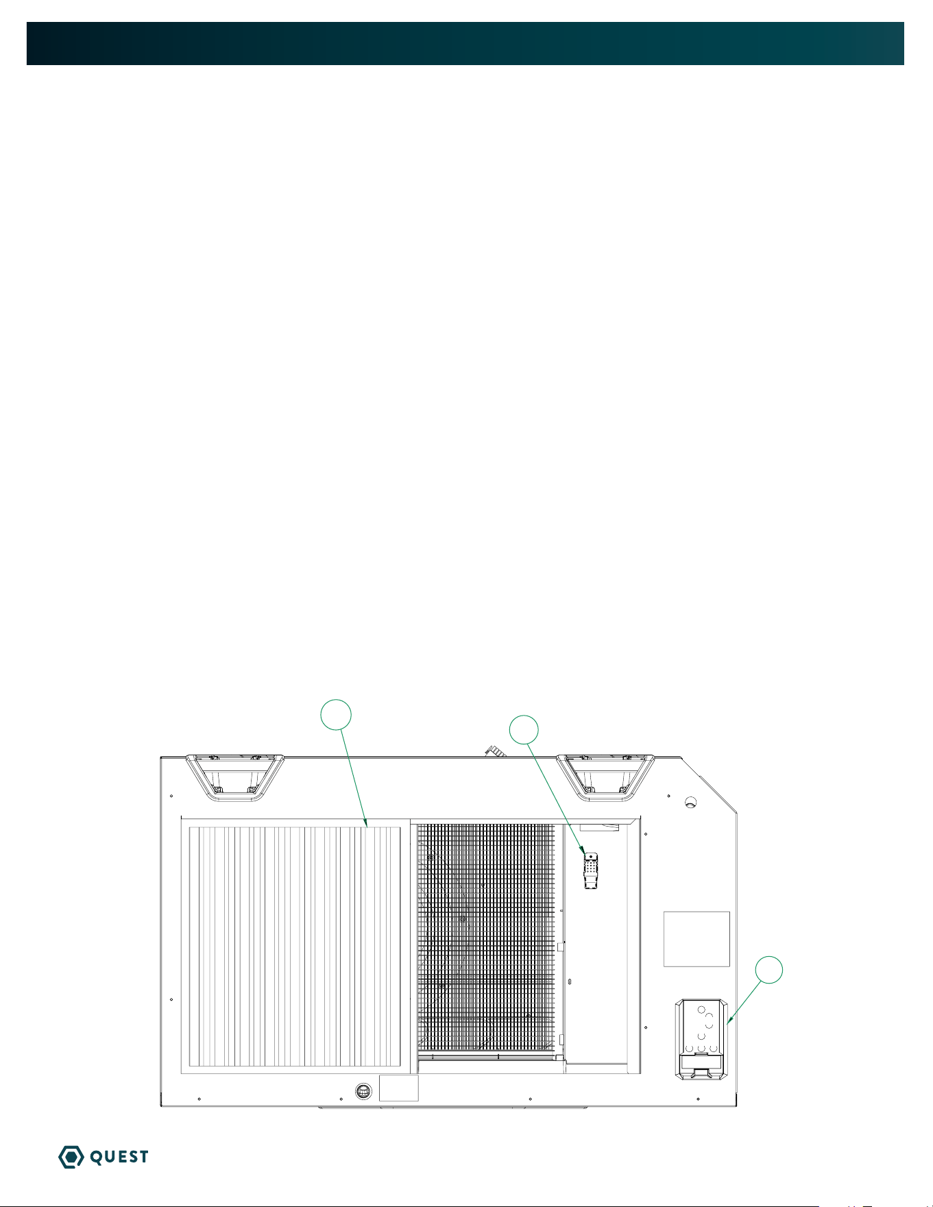
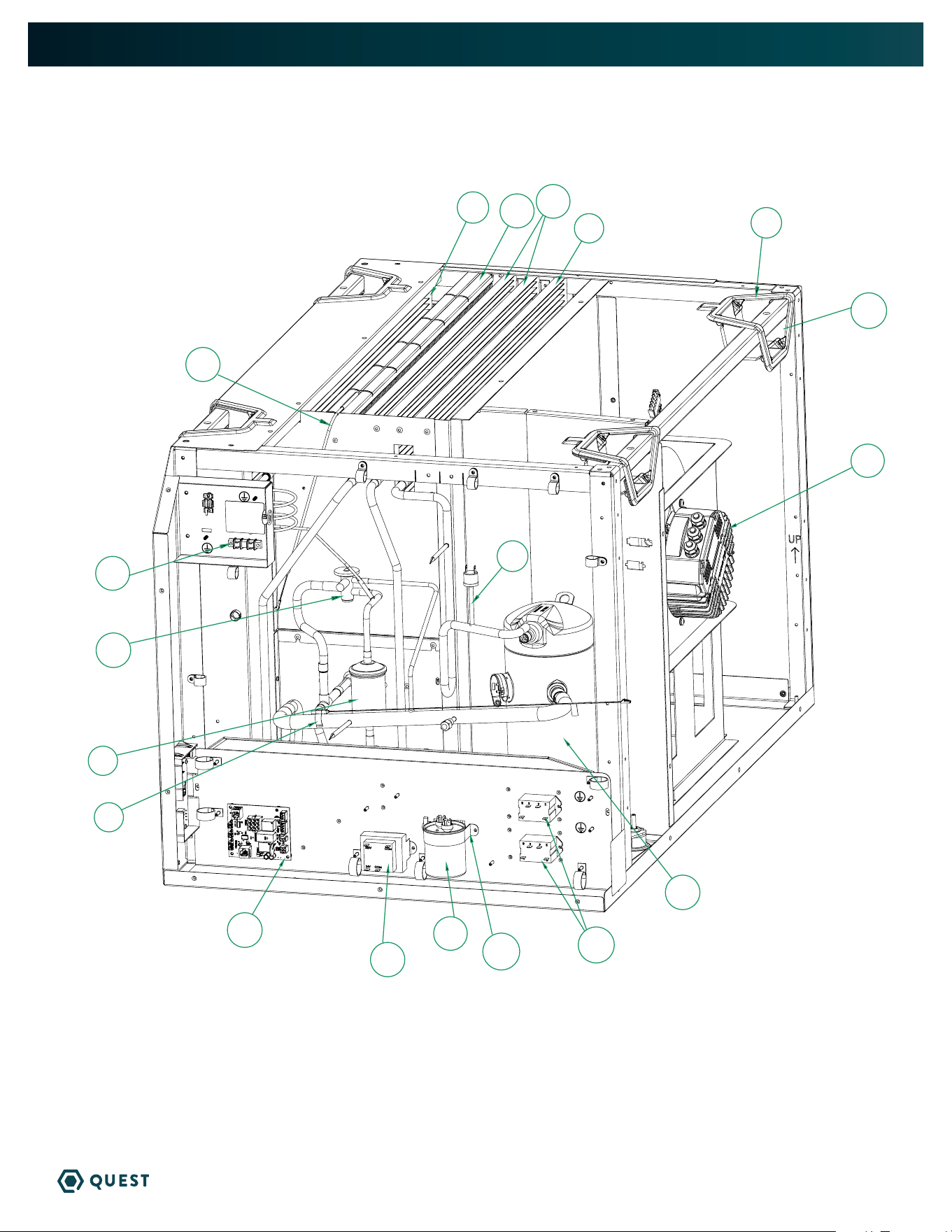
SERVICE PARTS LIST
Item Part No Description
1 4042733 TERMINAL BLOCK
2 4043873 TXV, 5.9 KW, 506Z
3 4042468 FILTER DRIER
4 4044271-01 THERMISTOR, CLIP-ON, 20”
5 4043877 PWR/CNTL ASSY 506Z
6 4031406 XFMR,50/60HZ,40VA (220V)
(4042945) XFMR,60HZ,40VA (277V)
7 4035949-04 CAPACITOR,40 MFD,440V,OIL
8 4039729 CLAMP,CAPACITOR,2.5” U-SHAPE
9 4022484 RELAY,SPST, 24V,30A
10 4043971 CPRSR,COPE,29CC,SCR,454B (230V)
(4043972) CPRSR,COPE,29CC,SCR,454B (277V)
11 4029507 CONTROL,HIGH PRESSURE,650 PSI
12 4043699 IMPELLER ASSY,EC355,230V
13 4038135 HANDLE,POCKET,6 SERIES
Item Part No Description
14 4043828 BEZEL,HANDLE
15 4043384-02 COIL,MICROCHANNEL,16MM
16 4043774-02 COIL,MICROCHANNEL,16MM,70/30
17 4044097-01 COIL,MCHE,2X17MM,1100DIST
18 4044269-01 PROBE,THERMSITOR,30”
19 4038233-01 AIR FILTER, 18 x 20 x 2”
20 4042061 SENSOR ,TEMP&RH,DIGITAL
21 4041909 DISPLAY ASSY,24VAC
Not Pictured
22 4043387 WIRE HARNESS, QUEST 506Z
23 4043703 WIRE HARNESS, CPRSR, 506Z
24 4043898 CORD,12/3,SJTW,250V-20A,6-20P
(4043899) CORD,12/3,SJTW,277V-20A,L7-20P
25 4038789-05 CABLE ASSY, RJ12,RVRS, 12”
Part No Qty Description
4028531 1 DEH 3000R Control, Remote
4032220 1 Kit, Pump
4038644 1 Drain Trap Kit
Part No Qty Description
4044432 1 Kit, Intake Duct
4044431 1 Kit, Exhaust Duct
OPTIONAL PARTS LIST
506 230v & 277v
3
1
2
4
8
9
6
7
5
10
11
11
21
18
17
16
15
12
14
13
15
19
20
19
QUEST 506 INSTALLATION, OPERATION, AND MAINTENANCE INSTRUCTIONS
QUESTCLIMATE.COM(877) 420-1330
506 230v & 277v
3
1
2
4
8
9
6
7
5
10
11
11
21
18
17
16
15
12
14
13
15
19
20
20
QUEST 506 INSTALLATION, OPERATION, AND MAINTENANCE INSTRUCTIONS
QUESTCLIMATE.COM(877) 420-1330
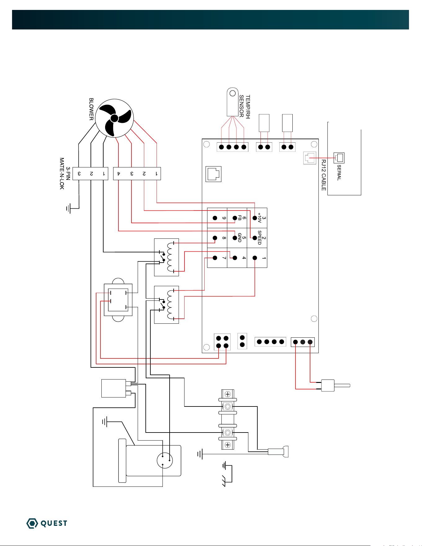
WIRING DIAGRAM
QUEST 506
BLK
WHT
GRN
PNK-9
YEL-8
GRY-12
BLU-11
VIO-18
WHT- 20
GRN-23
POWER CORD
4-PIN
MATE-N-LOK
BLOWER
RELAY
COMPRESSOR
RELAY
RED-13
GRN-10
BLK-17
COMPRESSOR
CAPACITOR
RED-14
BLU-7
GRN
IN
OUT
COM
BLK-16
RED-4
YEL-3
RED
YEL
WHT- 15
BLK
BLK-21
R
C
S
COMPRESSOR
WHT- 19
COMP-24V
COMP-24V
FAN-24V
FAN-24V
24V COM
24V COM
24V COM
24V COM
24V COM
24V COM
THERMISTOR
PROBE
UI
PROG
PHASE
REFRIGERANT
PRESSURE
SWITCH
24 VAC
RH IN EVAP AUX
GAS
SENSOR
BLU-6
BLU-5
THERMISTOR
PRESS SW
POWER BOARD
POWER BOARD
9-PIN
MATE-N-LOK
DISPLAY BOARD
DISPLAY BOARD
GRN-22
RED
YEL
WHT
BLU
BRN
BLU
GRN/YEL
P/N 4043708
Rev. A

21
QUEST 506 INSTALLATION, OPERATION, AND MAINTENANCE INSTRUCTIONS
QUESTCLIMATE.COM(877) 420-1330
SEE BACK FOR WARRANTY AND REGISTRATION
22
QUEST 506 LIMITED WARRANTY
QUESTCLIMATE.COM
(877) 420-1330
WARRANTOR:
Therma-Stor LLC
4201 Lien Rd
Madison, WI 53704
Telephone: 1-800-533-7533
WHO IS COVERED: This warranty extends only to the original end-user of the Quest 506 dehumidifier, and may not be
assigned or transferred.
FIRST YEAR WARRANTY: Therma-Stor LLC warrants that, for one (1) year the Quest 506 dehumidifier will operate free from
any defects in materials and workmanship, or Therma-Stor LLC will, at its option, repair or replace the defective part(s), free of
any charge.
SECOND THROUGH FIFTH YEAR WARRANTY: Therma-Stor LLC further warrants that for a period of five (5) years, the
condenser, evaporator, and compressor of the Quest 506 dehumidifier will operate free of any defects in material or
workmanship, or Therma-Stor LLC, at its option, will repair or replace the defective part(s), provided that all labor and
transportation charges for the part(s) shall be borne by the end-user.
END-USER RESPONSIBILITIES: Warranty service must be performed by a Servicer authorized by Therma-Stor LLC. If the end-
user is unable to locate or obtain warranty service from an authorized Servicer, he should call Therma-Stor LLC at the above
number and ask for the Therma-Stor LLC Service Department, which will then arrange for covered warranty service. Warranty
service will be performed during normal working hours.
The End-user must present proof of purchase (lease) upon request, by use of the warranty card or other reasonable and
reliable means. The end-user is responsible for normal care. This warranty does not cover any defect, malfunction, etc.
resulting from misuse, abuse, lack of normal care, corrosion, freezing, tampering, modification, unauthorized or improper
repair or installation, accident, acts of nature or any other cause beyond Therma-Stor LLC's reasonable control.
LIMITATIONS AND EXCLUSIONS: If any Quest 506 dehumidifier part is repaired or replaced, the new part shall be warranted
for only the remainder of the original warranty period applicable thereto (but all warranty periods will be extended by the
period of time, if any, that the Quest 506 Dehumidifier is out of service while awaiting covered warranty service).
UPON THE EXPIRATION OF THE WRITTEN WARRANTY APPLICABLE TO THE Quest 506 DEHUMIDIFIER OR ANY PART THEREOF, ALL OTHER WARRANTIES
IMPLIED BY LAW, INCLUDING MERCHANTABILITY AND FITNESS FOR A PARTICULAR PURPOSE, SHALL ALSO EXPIRE. ALL WARRANTIES MADE BY
THERMA-STOR LLC ARE SET FORTH HEREIN, AND NO CLAIM MAY BE MADE AGAINST THERMA-STOR LLC BASED ON ANY ORAL WARRANTY. IN NO EVENT
SHALL THERMA-STOR LLC, IN CONNECTION WITH THE SALE, INSTALLATION, USE, REPAIR OR REPLACEMENT OF ANY Quest 506 DEHUMIDIFIER OR
PART THEREOF BE LIABLE UNDER ANY LEGAL THEORY FOR ANY SPECIAL, INDIRECT OR CONSEQUENTIAL DAMAGES INCLUDING WITHOUT LIMITATION
WATER DAMAGE (THE END-USER SHOULD TAKE PRECAUTIONS AGAINST SAME), LOST PROFITS, DELAY, OR LOSS OF USE OR DAMAGE TO ANY REAL OR
PERSONAL PROPERTY.
Some states do not allow limitations on how long an implied warranty lasts, and some do not allow the exclusion or limitation of
incidental or consequential damages, so one or both of these limitation may not apply to you.
LEGAL RIGHTS: This warranty gives you specific legal rights, and you may also have other rights which vary from state to state.
IMPORTANT WARRANTY INFORMATION
DO NOT DISCARD
FOR INTERNAL
USE ONLY
REGISTER YOUR
NEW DEHUMIDIFIER
using the serial number
and part number at
thermastor.com/registration
or scan code above
PLACE LABEL HERE
SERIAL
NUMBER
PART
NUMBER