INSTALLATION, OPERATION AND
MAINTENANCE INSTRUCTIONS
QUEST
225
QUESTCLIMATE.COM / (877) 420-1330
Patents: thermastor.com/patents
Serial Number
Install Date
Sold By
TS-1244 08/23 REV A
Digital Controls
M-CoRR Technology
Industry-Leading Efficiency
Superior MERV-13 Air Filtration
Integrated Lift and Hang Points
CALIFORNIA
TITLE 24 COMPLIANT

2
QUEST 225 INSTALLATION, OPERATION AND MAINTENANCE INSTRUCTIONS
QUESTCLIMATE.COM(877) 420-1330
TABLE OF CONTENTS
Safety Precautions ............................................................3
1. Intended Application ....................................................4
2. Registrations .................................................................4
3. Specifications ................................................................4
4. Installation .....................................................................5
4.1 Location ...................................................................5
4.2 Electrical Requirements .....................................5
4.3 Condensate Water Removal ...............................6
4.4 Hanging Diagram .................................................7
4.5 Ducting ..................................................................8
4.6 Hard-Wiring ........................................................ 12
5. Control Options ........................................................... 16
5.1A On Board Dehumidistat ............................ 16
5.2B External Control Options ......................... 17
5.2 External Control.................................................. 18
6. Maintenance ................................................................ 18
6.1 Standard Air Filter ............................................... 18
6.2 Impeller Fan Oiling ............................................. 18
7. Service........ .................................................................. 19
7.1 Warranty ................................................................. 19
7.2 Technical Description ......................................... 19
7.3 Troubleshooting ................................................... 19
7.4 Refrigerant Charging .......................................... 21
7.5 Impeller Fan Replacement ................................. 21
7.6 Compressor/Capacitor Replacement .............. 21
7.6A Checking Compressor Motor Circuits ... 21
7.6B Replacing a Burnt Compressor .............. 22
7.6C Replacing Compressor-Nonburn Out .... 22
7.7 Remote Controls ................................................. 22
7.7A Humidity Control ...................................... 23
7.8 Defrost Thermostat ............................................ 23
7.9 Condensate Pump Kit ........................................ 23
8. Error Codes.......................... ....................................... 24
Wiring Diagram ................................................................ 25
Service Parts List ........................................................... 26
Optional Parts List ......................................................... 26
Warranty......... .................................................................. 28
4201 Lien Rd.
Madison, WI 53704
1-877-420-1330
Thermastor.com
© 2023 Therma-Stor LLC

3
QUEST 225 INSTALLATION, OPERATION AND MAINTENANCE INSTRUCTIONS
QUESTCLIMATE.COM(877) 420-1330
SAFETY PRECAUTIONS
Read the installation, operation and maintenance instructions carefully before installing and
operating this device. Proper adherence to these instructions is essential to obtain maximum benefit
from your Quest Dehumidifier.
READ AND SAVE THESE INSTRUCTIONS
» The device is designed to be installed INDOORS IN A SPACE THAT IS
PROTECTED FROM RAIN AND FLOODING.
» Install the unit with space to access the back or side panels for
maintenance and service. DO NOT INSTALL UNIT WITH THE SERVICE
PANELS INACCESSIBLE.
» Avoid directing the discharge air at people, or over the water in pool
areas.
» If used near a pool, spa or water; be certain there is NO chance the unit
could fall into the water, be splashed and that it is plugged into an outlet
that is a GROUND FAULT INTERRUPT protected circuit.
» DO NOT use the device as a bench or table.
» DO NOT place the device directly on structural members. Provide vibration
isolation in order to minimize operational vibration and/or noise.
» A drain pan MUST be placed under the unit if installed above a living area
or above an area where water leakage could cause damage
» Never operate a unit with a damaged power cord. If the power cord is
damaged it must be replaced by the manufacturer, its service agent, or
similarly qualified person in order to avoid a hazard.
» Make all electrical connections in accordance with the current edition of
the NEC ANSI/NFPA 70 and any national and local codes or ordinances
that may apply.
» Maintain a minimum 1ft. (.3m) clearance to avoid obstructing the air return
and supply.
» This appliance is not intended for use by persons (including children) with
reduced physical, sensory or mental capabilities, or lack of experience
and knowledge, unless they have been given supervision or instruction
concerning use of the appliance by a person responsible for their safety.
Children should be supervised to ensure that they do not play with the
appliance.
» Not intended for use at altitudes over 6500 ft (2000M).
4
QUEST 225 INSTALLATION, OPERATION AND MAINTENANCE INSTRUCTIONS
QUESTCLIMATE.COM(877) 420-1330
1. INTENDED APPLICATION FOR QUEST 225
The Quest 225 Dehumidifier is designed to operate in temperatures between 56° and 95°F.
In order to efficiently control humidity levels, the area in which the dehumidifier is to be operated must
be free of water intrusion or excessive fresh (outside) air infiltration. Before installing the Quest 225
Dehumidifier, water intrusion and air infiltration problems should be addressed or noted in calculations.
2. REGISTRATIONS
The Quest 225 Dehumidifier units conform to unified standard UL 60225-2-40, CSA C22,2#60225-2-40.
US Patents: D570,988 / 8,069,681 / 9,052,132.
3. SPECIFICATIONS @ 80°F/60% RH
UNIT
QUEST 225
4042800
BLOWER:
(TESTED WITH DUCT
COLLARS ON)
650 CFM @ 0.6” WG
POWER:
1150 Watts
SUPPLY VOLTAGE:
208V and 230V
1 Phase - 60 Hz
CURRENT DRAW:
5.3A @ 230V
5.6A @ 208V
MCA *
8.0A
MOP *
15A
RECOMMENDED
BREAKER SIZE:
15A
ENERGY FACTOR:
3.9 L/kWh
OPERATING TEMP:
56 F Min–95 F Max
WATER REMOVAL:
EFFICIENCY:
225 Pints/Day
8.2 Pints/kWh
AIR FILTER: MERV-13
Size: 22” x 20” x 2”
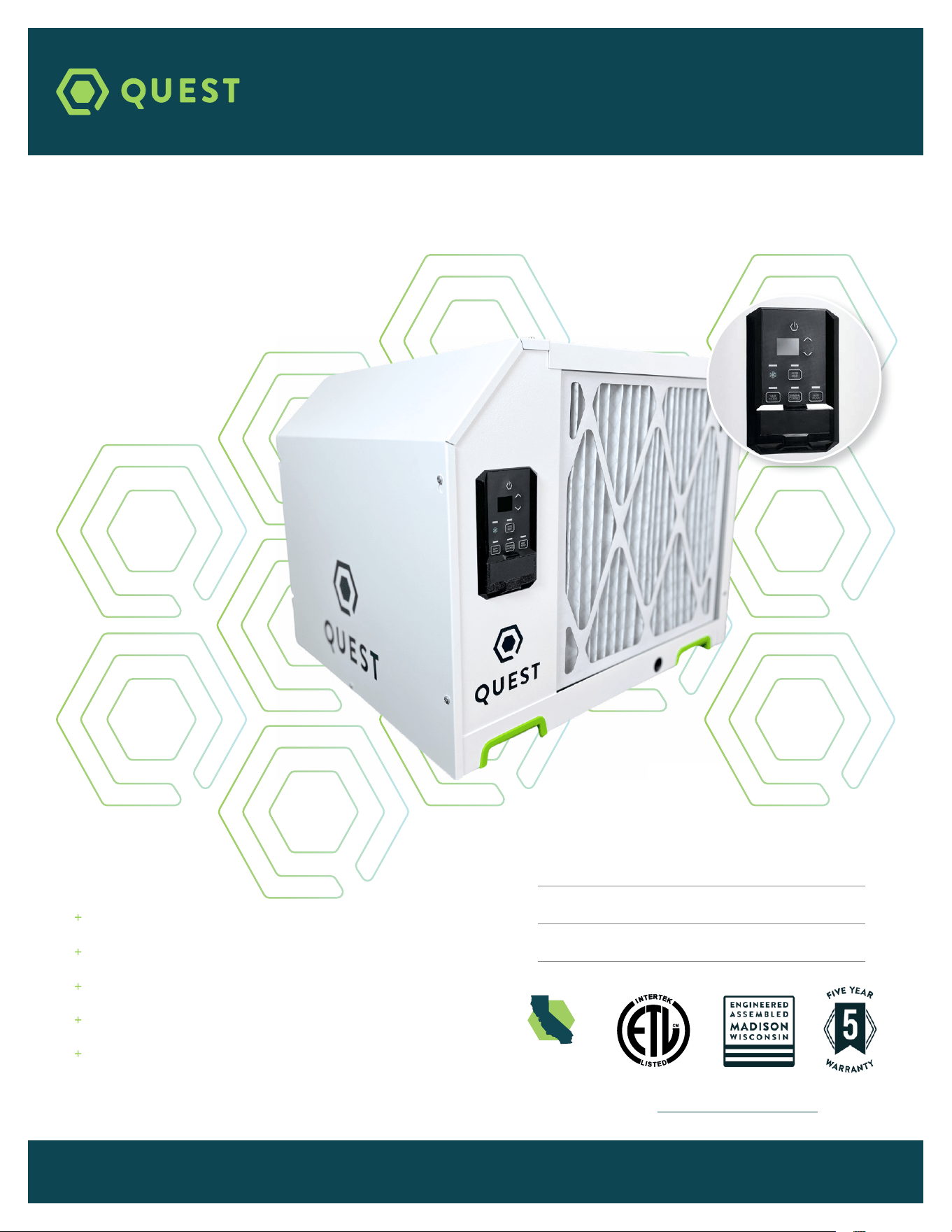
POWER CORD:
10’ 14/3 SJTW
NEMA 6-15P, 10’
DRAIN CONNECTION:
3/4” Threaded NPT
REFRIGERANT TYPE:
REFRIGERANT
AMOUNT:
R410A
4 lb 12 oz
DIMENSIONS:
WIDTH:
HEIGHT:
LENGTH:
WEIGHT:
Unit Shipping
23.6” 25”
20.9” 21”
26.8” 29”
130 lb 152 lb
* MCA = Minimum Circuit Ampacity
This number provides a qualified electrician with
the information needed to determine the minimum
wire size used in the circuit that feeds a single
dehumidifier.
* MOP = Maximum Overcurrent Protection
This number provides a qualified electrician with
the value of the maximum size circuit breaker that
may be used to protect the circuit that feeds a
dehumidifier.
Specifications are subject to change without notice.

5
QUEST 225 INSTALLATION, OPERATION AND MAINTENANCE INSTRUCTIONS
QUESTCLIMATE.COM(877) 420-1330
4. INSTALLATION
4.1 LOCATION
The Quest 225 Dehumidifier can be installed in a variety of locations to meet the owner’s needs as
listed below. In all cases keep the following cautions in mind:
» Place the Quest 225 Dehumidifier on supports that raise the base of the unit 6” above the
secondary drain pan so a P-trap can be installed. See Section 4.3.
» The Quest 225 Dehumidifier may be suspended with steel hanger, straps, or a suitable alternative
from structural members, unit must be supported from underneath. Don’t hang from sides or
ends. See section 4.3.
» If installing on ground, use included plugs to cover hanging locations on top of the machine.
» If hanging machine in air, use included plugs to cover holes in base pan for leveling feet.
4.2 ELECTRICAL REQUIREMENTS
The Quest 225 Dehumidifier plugs into NEMA rated receptacles. The amp draw under normal
operating conditions is listed on page 4. A ground fault interrupter protected circuit is required.
Install the remote hygrostat in a central area of the structure where it will sense the relative
humidity of the structure accurately. Do not install the hygrostat where it may not accurately sense
the relative humidity such as near HVAC supply registers, near exterior doors, or near a pool or spa.
The installer must supply the wiring between the Quest 225 Dehumidifier and the hygrostat. Be sure
to safely route the control wiring to prevent damage during installation. Be careful not to cross the
wires when connecting the Quest 225 Dehumidifier and the remote hygrostat.
The remote controls of the Quest 225 Dehumidifier are powered by a low voltage circuit (24 VAC)
and must NEVER contact or be connected to a high voltage circuit. The control terminals and remote
control are labeled and numbered to prevent confusion. Be sure to consult the electrical schematic
in this manual or inside the access panel of the Quest 225 Dehumidifier before making the control
connections.
CAUTION! Always disconnect the Quest 225 from a power source when
working with the high voltage control wires.
6
QUEST 225 INSTALLATION, OPERATION AND MAINTENANCE INSTRUCTIONS
QUESTCLIMATE.COM(877) 420-1330
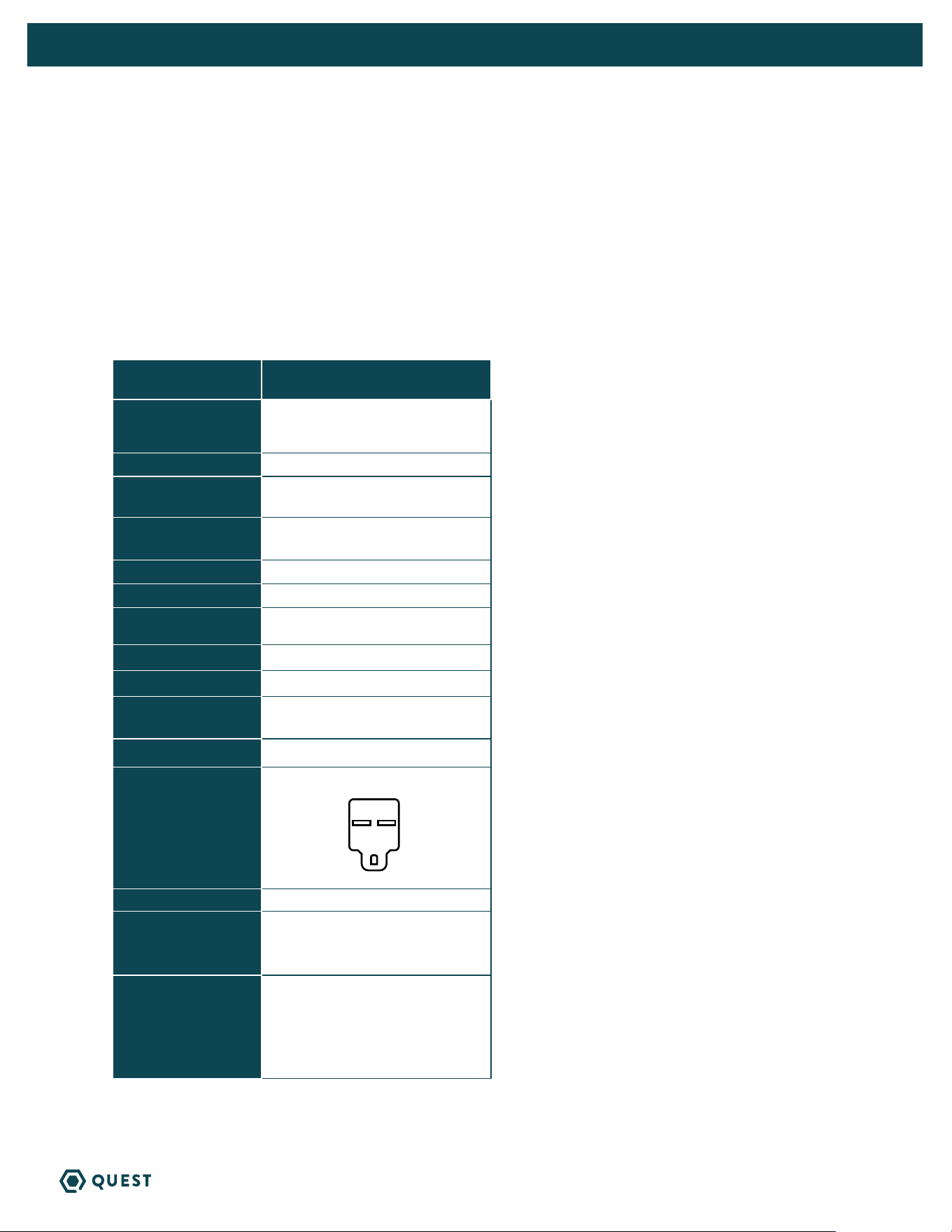
CAUTION! For proper drainage, the unit must be mounted so the drain outlet
is at least 6.75” above the floor drain, and must be fully supported under the base.
4.3 CONDENSATE WATER REMOVAL
Condensate drains by gravity via the drain port. Use 3/4” male NPT PVC pipe. An optional condensate
pump kit may be installed if a lift is required to dispose of the condensate. Optional parts list for
information on the kit.
FOLLOW DIAGRAM:
QUEST 225
H = 4”
J = 2”
L = 6.75”
Vent:
» Place vent after the trap.
» Vent should be open.
» Height of vent should be higher than drain outlet.
Cap:
» A clean out can be placed before trap but must be sealed with a cap.
Drain Line:
» Drain line should go in a downward slope to the drain.
» 1/4” drop per foot.
L
H
J
Drain Trap Configuration
VENT OPEN
CAP
7
QUEST 225 INSTALLATION, OPERATION AND MAINTENANCE INSTRUCTIONS
QUESTCLIMATE.COM(877) 420-1330
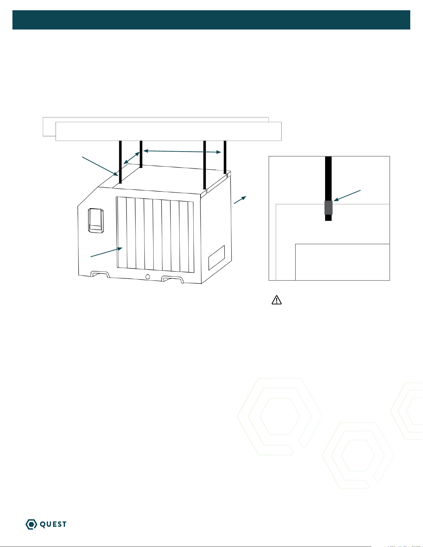
4.4 HANGING DIAGRAM
QUEST 225
Parts Needed: 4 pieces 3/8” threaded rod (not included)
4 - 3/8” threaded jam nuts (not included)
19.4”16.6”
3/8”
threaded rod
Intake Air
Treated Air
3/8” Jam Nuts
Threaded rods should be engaged
no less than 2” into machine.
8
QUEST 225 INSTALLATION, OPERATION AND MAINTENANCE INSTRUCTIONS
QUESTCLIMATE.COM(877) 420-1330
4.5 DUCTING
Return and supply duct collars are optional accessories for the Quest 225 and not included with the unit.
CAUTION! Do not connect with a static pressure greater than or equal to +1.0 WG. Contact
technical support at (877) 420-1330 for additional details.
DUCTING CONSIDERATIONS:
» All flexible ducting connected to the Quest 225 should be UL listed.
» A short piece of flexible ducting on all Quest 225 duct connections is recommended
to reduce noise and vibration transmitted to rigid ductwork in the structure.
» Use a minimum 10” diameter round or equivalent rectangular duct for total duct
lengths of up to 25’.
» Grills or diffusers on the duct ends must not excessively restrict airflow.
» A length of 8” or more of insulated flex duct or any other vibration isolating material on the
outlet of the Quest 225 will reduce air noise from the blower.
» When ducting two or three areas, use 8” or larger diameter branch ducting. When ducting to
four or more areas, use 6” or larger diameter branch ducting. Provisions must be made to provide
airflow supply locations to the central return location. Proper air distribution is important to
ensure even humidity control and heat distribution throughout the structure.
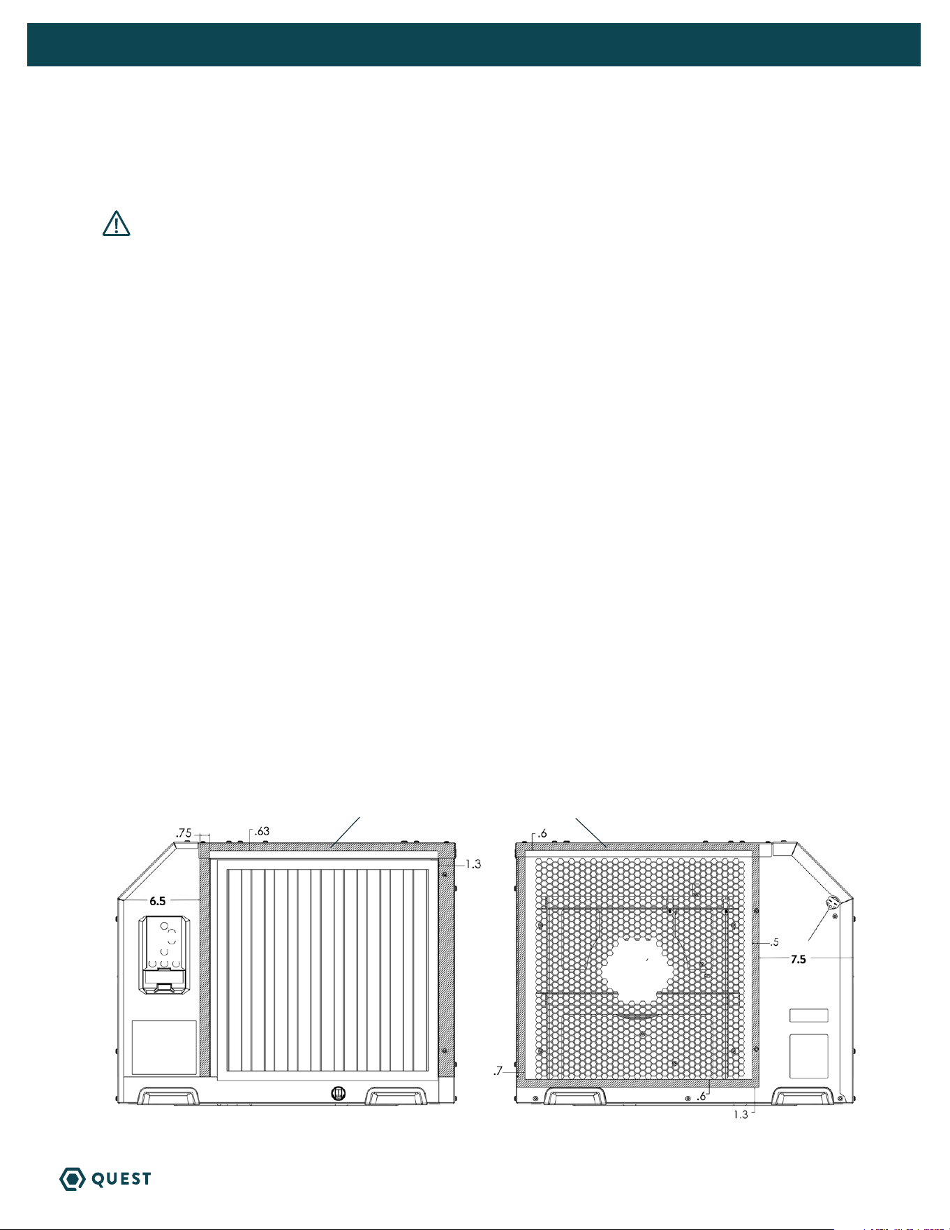
QUEST 225 SUPPLY AND RETURN DUCT KIT (P/N 4043235)
If factory duct kit accessory was purchased, follow instructions included with duct kit.
If owner chooses to have a licensed HVAC contractor fabricate a duct kit, please follow the drawing below
for safe zones for self tapping screws.
HATCH AREA REPRESENTS SAFE ZONE FOR FASTENERS.
9
QUEST 225 INSTALLATION, OPERATION AND MAINTENANCE INSTRUCTIONS
QUESTCLIMATE.COM(877) 420-1330
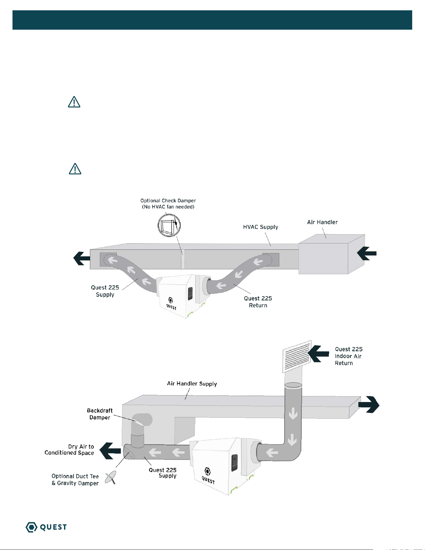
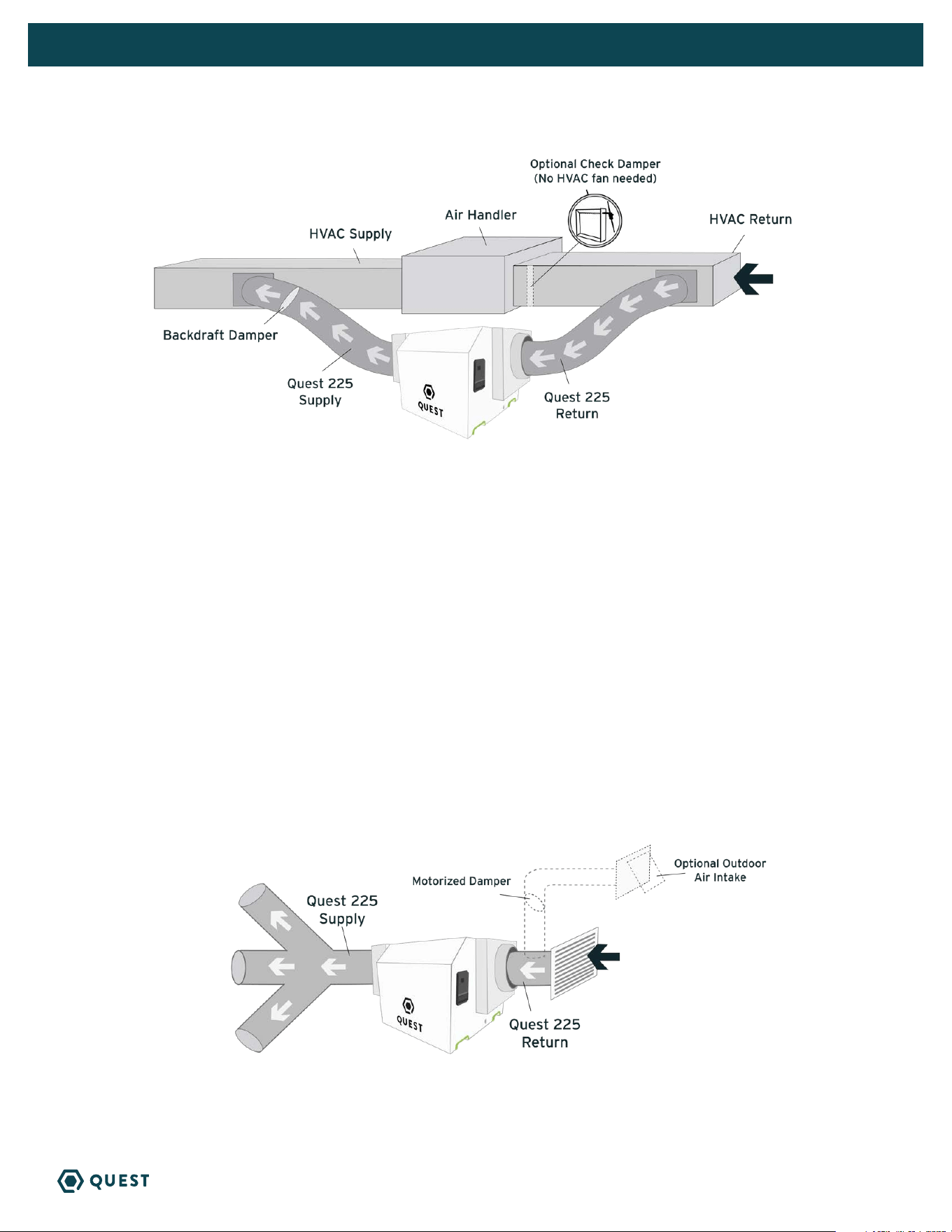
B. DEDICATED RETURN TO SUPPLY
DUCTING TO HVAC OPTIONS
A. HVAC SUPPLY TO SUPPLY
CAUTION! To avoid the dehumidifier cycling in and out of DEFROST, it is recommended
that the leaving air temperature of the A/C coil is not below 55°F. Also, this install is not
recommended for climates where the heating system will run during the spring and fall times of
year, as this could diminish the water removal capability of the dehumidifier. If the Check Damper
is not used, it is important to have the HVAC system fan ON when the dehumidifier is ON to
prevent backflow of air.
WARNING! Due to pressure resistance it is not recommended to use the optional
outdoor air intake when installing the dehumidifier supply to supply.
10
QUEST 225 INSTALLATION, OPERATION AND MAINTENANCE INSTRUCTIONS
QUESTCLIMATE.COM(877) 420-1330
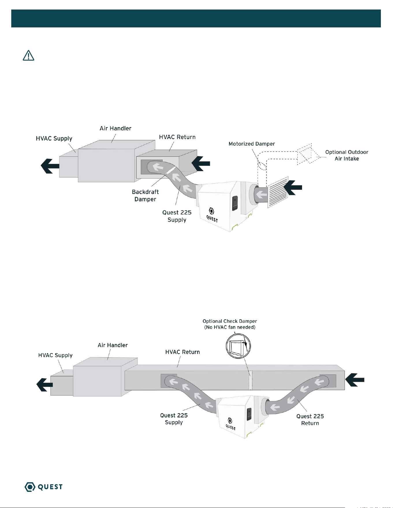
CAUTION! PLEASE NOTE: Return to Return installs are to be considered last resort options and are not
recommended. The dehumidifier will heat the AC cooling coils which diminishes the amount of water the AC system
will remove when operating. If this installation is chosen, the dehumidifier must activate the HVAC blower and AC
calls need to lock out the dehumidifier from running. Please check your local codes prior to installing.
C. DEDICATED QUEST RETURN TO HVAC RETURN
D. HVAC RETURN TO HVAC RETURN
Create a separate return for the Quest 225 Dehumidifierin a central area of the building.
Installing the supply air from the Quest 225 Dehumidifier to the return of the HVAC system requires
the HVAC fan to run when the Quest Dehumidifier is operating.
NOTE: If Check Damper is not in place, the HVAC fan must ON when the dehumidifier is in operation.
Quest 225 Indoor
Air Return
11
QUEST 225 INSTALLATION, OPERATION AND MAINTENANCE INSTRUCTIONS
QUESTCLIMATE.COM(877) 420-1330
E. HVAC RETURN TO HVAC SUPPLY
F. NO EXISTING DUCTWORK INSTALLATION
When installing the Quest 225 Dehumidifier in a structure that does not have a forced-air HVAC system,
a single return for the dehumidifier should be installed in a central location. The supply air should be ducted back
into the space you want to dry. Proper air distribution is important for optimal performance of the dehumidifier.
Install a 6” insulated duct from outside, teeing into the 14” return duct of the Quest 225 Dehumidifier
to provide outdoor air ventilation (optional).
An 14” diameter duct is recommended for branches to larger areas.
If the Check Damper is not in place,
the HVAC fan must be ON when
the dehumidifier is in operation.
Anything greater than 0.4” of static
requires HI fan setting. Anything greater
than 0.7” of static requires HI override
(99). Anything greater than 0.9” is not
recommended.
Check damper should be in place between
the Return and Supply connections of the
dehumidifier.
Quest 225 Indoor
Air Return
12
QUEST 225 INSTALLATION, OPERATION AND MAINTENANCE INSTRUCTIONS
QUESTCLIMATE.COM(877) 420-1330
4.6 HARD-WIRING INSTRUCTIONS
WARNING! Servicing the Quest 225 Dehumidifier, with its high pressure
refrigerant system and high voltage circuitry presents a health hazard which could
result in death, serious bodily injury, and/or property damage. Only qualified service
people should service this unit.
TOOLS REQUIRED:
» T25 Torx Driver
» 11/32” Driver
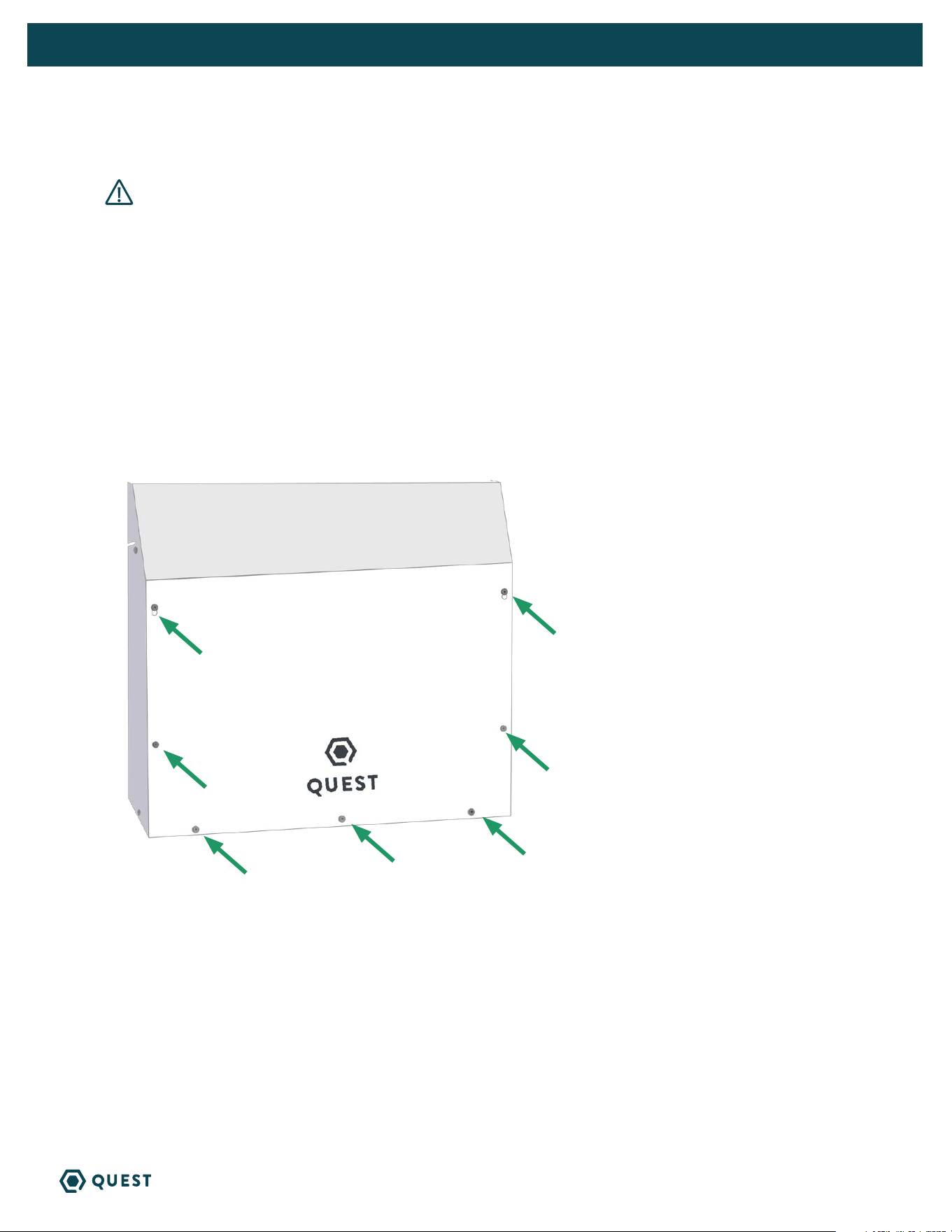
Following all local and national electrical codes and standards, route electrical service to the location
that the dehumidifier will be installed.
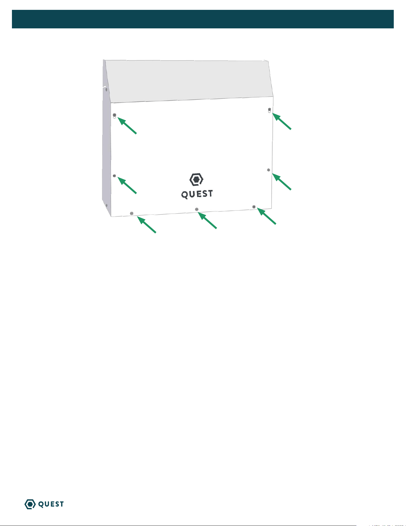
Remove 7 screws on access panel using T25 Torx driver, remove panel.
13
QUEST 225 INSTALLATION, OPERATION AND MAINTENANCE INSTRUCTIONS
QUESTCLIMATE.COM(877) 420-1330
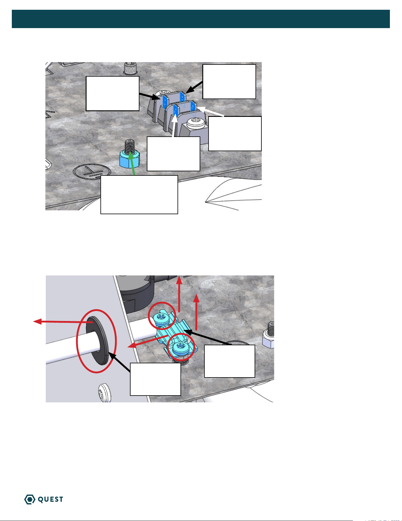
Disconnect POWER CORD BLACK wire from terminal
Disconnect POWER CORD WHITE wire from terminal.
Use 11/32” driver to remove nut from ground stud and disconnect POWER CORD GREEN wire from
ground stud.
Remove the 2 screws holding the cord retention bracket using T25 Torx driver and remove retention
bracket.
Remove power cord and black bushing.
Route incoming power service wires through 7/8” hole and secure using clamps intended for the
conduit or cable.
Disconnect
power cord
black wire
Wire harness
black wire
Wire harness
white wire
Disconnect
power cord
white wire
Disconnect
power cord green wire
from ground stud
Remove cord
retention
bracket
Remove
bushing from
7/8” hole
14
QUEST 225 INSTALLATION, OPERATION AND MAINTENANCE INSTRUCTIONS
QUESTCLIMATE.COM(877) 420-1330
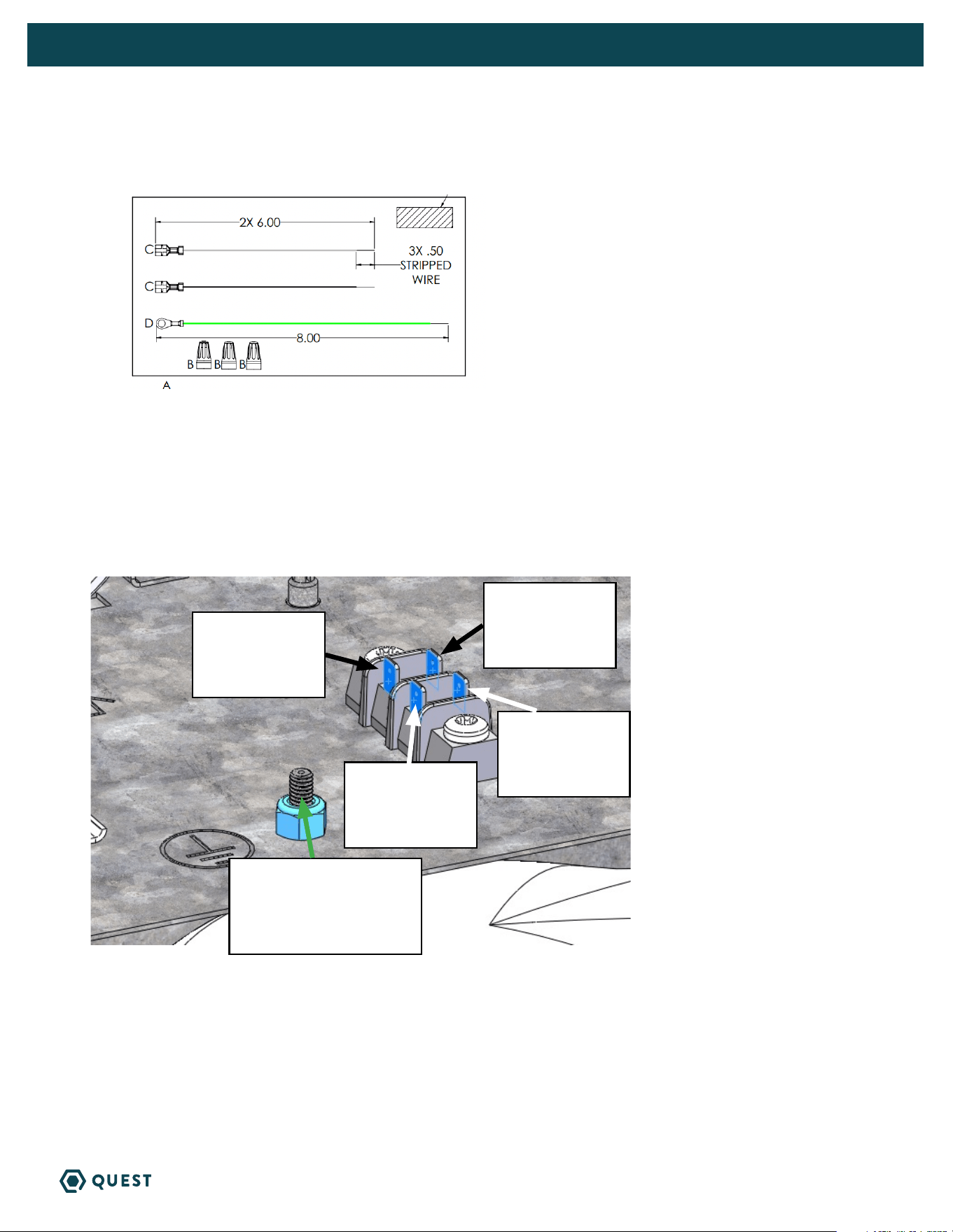
Hardwire kit with jumper wires can be found in the pack part kit.
Connect BLACK and WHITE jumper wires to terminal block as shown.
Place GREEN jumper wire ring terminal on ground stud and use 11/32” driver to secure nut to stud.
Attach incoming service LINE 1 wire to BLACK jumper wire with the provided wirenut.
Attach incoming service LINE 2 wire to WHITE jumper wire with the provided wirenut.
Attach incoming service GROUND wire to GREEN jumper wire with the provided wirenut.
Connect black
jumper wire
Wire harness
Black wire
Wire harness
white wire
Connect white
jumper wire
Green jumper wire to
ground stud
15
QUEST 225 INSTALLATION, OPERATION AND MAINTENANCE INSTRUCTIONS
QUESTCLIMATE.COM(877) 420-1330
Replace access panel using T25 Torx driver to secure 7 screws.
16
QUEST 225 INSTALLATION, OPERATION AND MAINTENANCE INSTRUCTIONS
QUESTCLIMATE.COM(877) 420-1330
5. CONTROL OPTIONS
The Quest 225 Dehumidifier can be controlled by its on board dehumidistat or with an external control
using its low voltage terminal block.
5.1A QUEST 225 ONBOARD DEHUMIDISTAT
Off Mode: Fan, Compressor, Display and all LEDs are off
To Turn Unit On: Press the power button
On Mode: Display is on and shows the set point (Initial set point: 55% RH)
To Change Set Point:
» Press the up or down arrow once, the 2-digit display will begin to blink.
» Adjust to desired RH. Each push of the button will change the SP 1% RH.
» After 6 seconds without a button being pushed the number showing will become the new SP
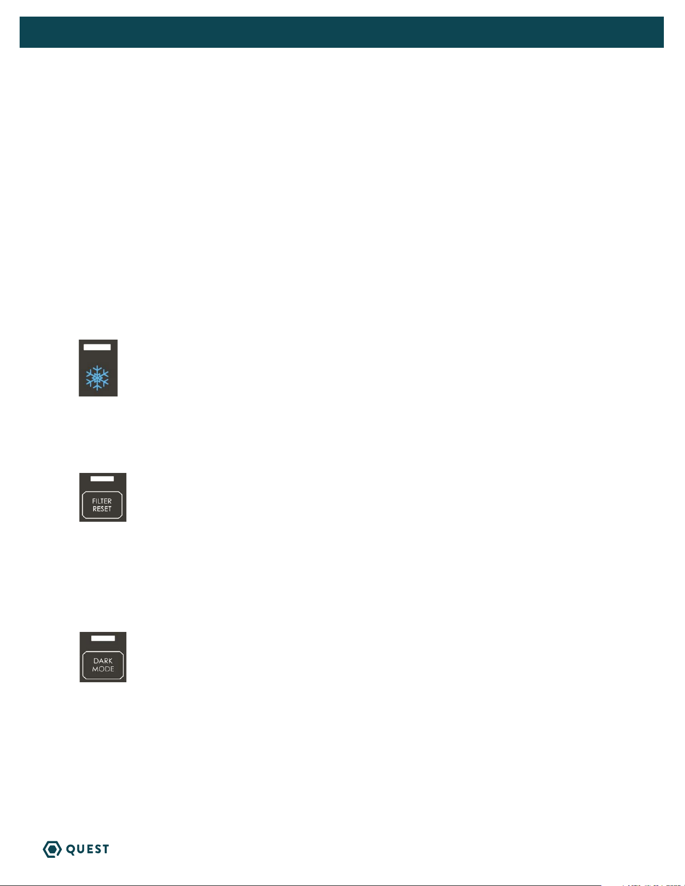
DEFROST LIGHT
» The light over the snowflake will light up when defrost is occurring (ice is detected on coils). The
fan will be on, and the compressor will be off during defrost.
FILTER RESET
» Filter reset button will light up after the fan has been running for 2,000 hours, or if the pressure
switch detects excessive pressure build-up indicating that the filter must be changed.
» After changing the filter, press and hold the filter reset button to reset the 2,000-hour timer. Light
flashes while button is held.
DARK MODE
» Press the Dark Mode button to activate Dark Mode.
» Once Dark Mode is activated, lights will remain on for 20 seconds before the unit’s hygrostat will go
dark. Dark Mode light will flash for 3 seconds before unit goes dark.
» Unit will temporarily leave dark mode when any button is pushed and will go dark 20 seconds after
the last button is pushed.
» To turn off Dark Mode, press the Dark Mode button and ensure light above Dark Mode button is off.
» This mode is for applications where the user would like the unit to operate without emitting any light.
17
QUEST 225 INSTALLATION, OPERATION AND MAINTENANCE INSTRUCTIONS
QUESTCLIMATE.COM(877) 420-1330
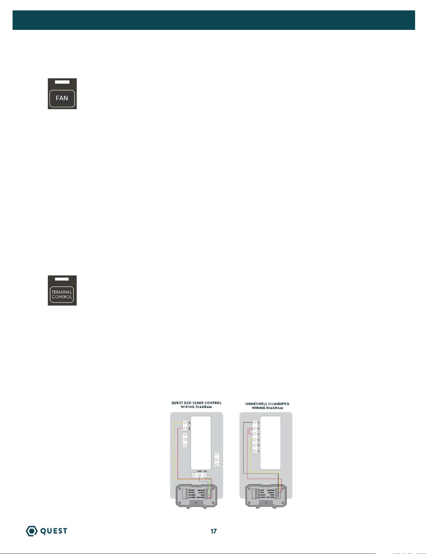
FAN
Pressing the Fan button alternates the unit between 3 fan speeds:
» (Hi)gh: Increased fan speed to be used exclusively in ducted applications. Deactivates filter-life
compensation mode.
» (Au)to: Default fan speed. Filter-life compensation mode active.
» (Lo)w: Decreased fan speed that lowers the volume and performance of the unit. Deactivates filter-
life compensation mode.
Filter-life compensation mode measures the static pressure increase due to the filter particulate build-up
and increases fan speed to maintain optimum airflow and performance.
Changing Max Fan Speed
» Hold the FAN button for 3 seconds, the 2-digit display will begin to flash.
» Once the display is flashing, the maximum fan speed can be adjusted 1% at at time (in the range of
20-99%).
» The new maximum fan speed can be locked by not pressing any buttons for 6 seconds or by pressing
the FAN button.
» This will disable filter life compensation functionality.
TERMINAL CONTROL
» When the Terminal Control button is pressed, the display will show “tc”.
» The Terminal Control button is used to activate the “DEHUM” input on the terminal block. (see
section 5.1B)
» This must be activated when an external control is used to control RH. When Terminal Control is
active, the internal RH sensor is disabled.
5.1B QUEST 225 EXTERNAL CONTROL OPTIONS
Quest offers three external control options: Quest DEH 3000R and Honeywell Humidipro.
NOTE: 22 ga wire needed for sensor
4028531
4041649
18
QUEST 225 INSTALLATION, OPERATION AND MAINTENANCE INSTRUCTIONS
QUESTCLIMATE.COM(877) 420-1330
5.2 QUEST 225 EXTERNAL CONTROL
Remove the cover from the user interface to expose the terminal block inputs & outputs.
Quest 225 Terminal Block Control Operations:
DEHUM: Dehumidification (Fan and Compressor) Control Input.
24VAC: Transformer High Side Output to External Control.
Fan: Fan Control Input.
24V COM: 24VAC Power Transformer Neutral Side Output to External Control.
FLOAT: External Low Voltage Float Switch or Water Sensor Input (Use Normally Closed Switch).
FLOAT: External Low Voltage Float Switch or Water Sensor Input (Use Normally Closed Switch).
Alarm: Normally Closed Relay Output - Indicates when dehumidifier is in an alarm state.
Alarm: Normally Closed Relay Output - Indicates when dehumidifier is in an alarm state.
NOTE: Alarm terminals are used to interface with a remote alarm or building automation
system. The terminals switch when the unit has a malfunction and are factory set to
“normally closed” but can be changed to “normally open”.
6. MAINTENANCE
WARNING! NOTE: Do not operate the unit without the filter or with a less effective
filter. The heat exchange coils inside the unit could become clogged and require disassembly
to clean. Filter non-compliance invalidates the product warranty.
6.1 STANDARD AIR FILTER
The Quest 225 Dehumidifier ships with a standard MERV-13 efficient pleated fabric filter. This filter should
be checked every six months. Operating the unit with a dirty filter will reduce dehumidifier capacity and
efficiency and may cause the compressor to cycle off and on unnecessarily on the defrost control.
To access the air filter, remove the filter access panel from the end of the Quest 225 Dehumidifier.
The filter should be readily visible and can be removed by pulling it straight out of the Quest 225
Dehumidifier.
We recommend changing the filter at least every 6 months. For agriculture we recommend changing the
filter with every grow cycle.
6.2 IMPELLER FAN OILING
The impeller fan motor is factory lubricated for many years of normal operation, and no further oiling is
required.
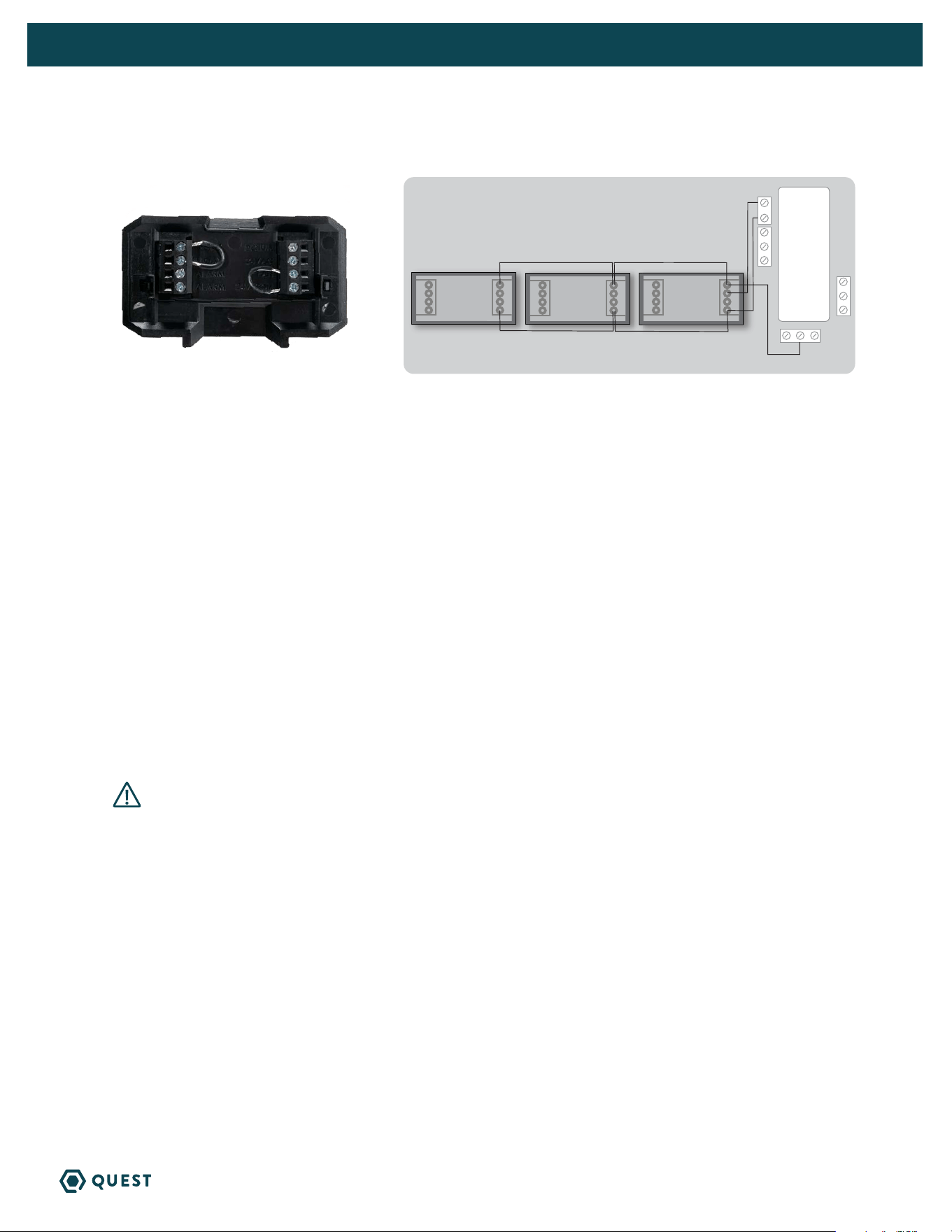
24VAC
COMP FAN
QUEST DEH 3000R CONTROLLER
QUEST 225 -
UNIT#2
QUEST 225 -
UNIT#3
QUEST 225 -
UNIT#1
*NOTE - DO NOT WIRE IN “FAN” TERMINAL WITH THIS APPLICATION
ALARM
FLOAT
FLOAT
FAN
24V COM
ALARM
DEHUM
24VAC
ALARM
FLOAT
FLOAT
FAN
24V COM
ALARM
DEHUM
24VAC
ALARM
FLOAT
FLOAT
FAN
24V COM
ALARM
DEHUM
24VAC
DAISY CHAIN
To order, contact your dealer, call 1-877-420-1330, or go to: www.questclimate.com/product-category/accessories
QUEST DEH 3000R CONTROLLER

19
QUEST 225 INSTALLATION, OPERATION AND MAINTENANCE INSTRUCTIONS
QUESTCLIMATE.COM(877) 420-1330
7. SERVICE
WARNING! Servicing the Quest 225 with its high pressure refrigerant system
and high voltage circuitry presents a health hazard which could result in death,
serious bodily injury, and/or property damage. Only qualified service people should
service this unit.
7.1 WARRANTY
A warranty certificate has been enclosed with this unit; read it before any repair is initiated. If a warranty
repair is required, call the factory first at 1-877-420-1330 for warranty claim authorization and technical
assistance.
7.2 TECHNICAL DESCRIPTION
The Quest 225 Dehumidifier uses a refrigeration system similar to an air conditioner’s to remove heat
and moisture from incoming air, and add heat to the air that is discharged.
Hot, high-pressure refrigerant gas is routed from the compressor to the condenser coil. The refrigerant
is cooled and condensed by giving up its heat to the air that is about to be discharged from the unit. The
refrigerant liquid then passes through a filter/drier and expanion device which causes the refrigerant
pressure and temperature to drop. It next enters the evaporator coil where it absorbs heat from the
incoming air and evaporates. The evaporator operates in a flooded condition, which means that all
the evaporator tubes contain liquid refrigerant during normal operation. A flooded evaporator should
maintain nearly constant pressure and temperature across the entire coil, from inlet to outlet.
The compressor collects the cool refrigerant gas and compresses it to a high pressure and temperature
to repeat the process.
7.3 TROUBLESHOOTING
Unit Test to determine problem:
1. Detach any exterior control wiring by removing terminal block but jump both FLOAT terminals
together.
2. Reinstall terminal block into the control.
3. Plug unit in to known good power outlet. 208 to 240 volts.
4. Power unit on by pressing power button on top of control.
5. Make sure the Terminal Control light is NOT illuminated. Press button to change.
6. Press down arrow to set the unit below 20% until “on” is displayed. This will force the unit on.
7. Listen for the fan to turn on almost immediately.
8. Wait 1 to 2 minutes for the compressor to turn on.
9. If these tests work, the problem is most likely in the control or field wiring.
Neither fan nor compressor running. Dehumidification is being called for. No fan call.
1. Unit unplugged or no power to outlet.
2. Humidity control set too high.
3. Loose connection in internal or control wiring.
4. Bad control or power board.
5. Defective control transformer.

20
QUEST 225 INSTALLATION, OPERATION AND MAINTENANCE INSTRUCTIONS
QUESTCLIMATE.COM(877) 420-1330
Compressor is not running. Dehumidification is being called for. No fan call.
1. Defective compressor run capacitor.
2. Loose connection in compressor circuit.
3. High pressure switch open or unplugged.
4. Defective compressor.
5. Compressor relay defective or unplugged.
6. Temp & RH sensor reading above 120°F or below 40°F, or sensor is bad or unplugged.
Compressor cycles on and off. Dehumidification is being called for. No fan call.
1. Low ambient temperature and/or humidity causing unit to cycle through defrost mode.
2. Evaporator temp sensor bad or unplugged.
3. Defective compressor.
4. High pressure switch defective.
5. Dirty air filter(s) or air flow restricted.
6. Bad control or power board.
Fan is not running. Dehumidification or fan is being called for.
1. Loose connection in fan circuit.
2. Obstruction prevents fan impeller rotation.
3. Defective fan.
4. Bad control or power board.
Low dehumidification capacity (evaporator is frosted continuously). Dehumidification is being called for.
1. Evaporator temp sensor bad or unplugged.
2. Low refrigerant charge.
3. Dirty air filter(s) or air flow restricted.
4. Excessively restrictive ducting connected to unit.
Unit removes some water, but not as much as expected.
1. Air temperature and/or humidity have dropped.
2. Humidity meter and or thermometer used are out of calibration.
3. Unit has entered defrost cycle.
4. Air filter dirty.
5. Low refrigerant charge.
6. Air leak (eg. loose cover or ducting leaks).
7. Defective compressor.
8. Restrictive ducting.
9. Unit is in (Lo)w fan mode.
10. Evaporator temp sensor bad or unplugged.
11. Temp and RH sensor off calibration. Reading lower than actual.
12. Air pressure switch off calibration.

21
QUEST 225 INSTALLATION, OPERATION AND MAINTENANCE INSTRUCTIONS
QUESTCLIMATE.COM(877) 420-1330
Filter Change Light illuminated (too frequently):
1. Change filter if dirty.
2. Hold filter change button to reset filter life hours.
3. Ducting configuration causing poor airflow. Disable filter change light by selecting a different fan
speed.
7.4 REFRIGERANT CHARGING
If the refrigerant charge is lost due to service or a leak, a new charge must be accurately weighed in. If
any of the old charge is left in the system, it must be recovered before weighing in the new charge. Refer
to the unit nameplate for the correct charge weight and refrigerant type.
7.5 IMPELLER FAN REPLACEMENT
The motorized impeller fan is a unitary assembly consisting of the motor and impeller fan. If defective,
the complete assembly must be replaced.
1. Unplug the power cord.
2. Remove the access panel, and top panel.
3. Remove the screws attaching the impeller fan support bracket to the base.
4. Disconnect the impeller fan leads inside the electric box.
5. Remove fan/bracket assembly by removing 3 screws from the bracket and inlet ring assembly.
6. Remove the defective impeller fan from the bracket and replace with it with the new impeller fan.
7. Reassemble the new impeller fan by reversing the above procedure. Note: There are two pins on the
backside of the cabinet that must align with the two holes in the impeller fan support bracket.
7.6 COMPRESSOR/CAPACITOR REPLACEMENT
This compressor is equipped with a run capacitor, but no start capacitor or start relay.
7.6A CHECKING COMPRESSOR MOTOR CIRCUITS
Perform the following tests if the impeller fan runs but the compressor does not with a call for
dehumidification.
1. Remove the cabinet side to gian access to the electrical components.
2. Plug in the unit and turn the humidity control to ON. Check for volts from compressor black wires on
compressor relay to white wire on compressor capacitor using an AC voltmeter.
2.1 If correct voltage is present, go to next step.
2.2 If no voltage, there may be a loose connection in the compressor circuit. Test each component
for continuity. See the appropriate section if a defect is suspected.
3. Unplug the unit and then disconnect the connector from the side of the compressor. Using an
ohmmeter, check continuity between the points listed below.
4. Compressor terminals C and S: No continuity indicates an open start winding. The compressor must
be replaced. Normal start winding resistance is 3 to 7 ohms.
5. Compressor terminals C and R: No continuity indicates an open run winding. The compresor must be
replaced. Normal run winding resistance is .5 to 2 ohms.
6. Compressor terminal C and compressor case: Continuity indicates a grounded motor. The compressor
must be replaced.
7. Disconnect the wires from the run capacitor. The capacitor is shorted and must be replaced if
continuity exists between any terminal and ground.

22
QUEST 225 INSTALLATION, OPERATION AND MAINTENANCE INSTRUCTIONS
QUESTCLIMATE.COM(877) 420-1330
8. Using capacitor or MFD setting on meter test between both capacitor terminals. Compare reading to
capacitor spec on capacitor.
9. If the above test pass but the compressor does not work, the compressor has an internal mechanical
defect and must be replaced.
7.6B REPLACING A BURNT COMPRESSOR
The refrigerant and oil mixture in a compressor is chemically very stable under normal operating conditions.
However, when an electrical short occurs in the compressor motor, the resulting high temperature arc causes
a portion of the refrigerant oil mixture to break down into carbonaceous sludge, a very corrosive acid, and
water. These contaminants must be carefully removed otherwise even small residues will attack replacement
compressor motors and cause failures.
The following procedure is effective only if the system is monitored after replacing the compressor to insure
that the clean up was complete.
1. This procedure assumes that the previously listed compressor motor circuit tests revealed a shorted or
open winding.
2. Remove and properly dispose of the system charge. DO NOT vent the refrigerant or allow it to contact your
eyes or skin.
3. Remove the burned out compressor. Use rubber gloves if there is any possibility of contacting the oil or sludge.
4. To facilitate subsequent steps, determine the type of burn out that occurred. If the discharge line shows no
evidence of sludge and the suction line is also clean or perhaps has some light carbon deposits, the burn out
occurred while the compressor was not rotating. Contaminants are therefore largely confined to the compressor
housing. A single installation of liquid and suction line filter/driers will probably clean up the system.
If sludge is evident in the discharge line, it will likely be found in the suction line. This indicates the compressor
burned out will running. Sludge and acid have been pumped throughout the system. Several changes of the
liquid and suction filter/driers will probably be necessary to cleanse the system.
5. Correct the system fault that caused the burn out. Consult the factory for advice.
6. Install the replacement compressor with a new capacitor and an oversized liquid line filter.
In a running burn out, install an oversized suction line filter/drier between the accumulator and compressor.
Thoroughly flush the accumulator with refrigerant to remove all trapped sludge and to prevent the oil hole
from becoming plugged. A standing burn out does not require a suction line filter/drier.
7. Evacuate the system with a good vacuum pump and accurate vacuum gauge. Leave the pump on the system
for at least an hour.
8. Operate the system for a short period of time, monitoring the suction pressure to determine that the suction
filter is not becoming plugged. Replace the suction filter/drier if pressure drop occurs. If a severe running burn
out has occurred, several filter/driers may have to be replaced to remove all of the acid and moisture.
NOTE: NEVER use the compressor to evacuate the system or any part of it.
7.6C REPLACING A COMPRESSOR, NON BURN OUT
Remove the refrigerant from the system. Replace the compressor and liquid line filter/drier. Charge the
system to 50 PSIG and check for leaks. Remove the charge and weigh in the refrigerant quantity listed on the
nameplate. Operate the system to verify performance.
7.7 REMOTE CONTROLS
The Quest 225 Dehumidifier is controlled by devices mounted on a panel that is remote from the unit. You
may or may not have the devices listed below depending on the model of the remote hygrostat you purchased.

23
QUEST 225 INSTALLATION, OPERATION AND MAINTENANCE INSTRUCTIONS
QUESTCLIMATE.COM(877) 420-1330
If the Quest 225 Dehumidifier fails to operate as desired, always check the settings of the controls to ensure
that they are correct. Check that the controls are receiving 24VAC from the Quest 225 Dehumidifier. Check the
connections between the Quest 225 Dehumidifier, the hygrostat, and the field control wiring.
7.7A HUMIDITY CONTROL
The humidity control is an adjustable switch that closes when the relative humidity of the air in which it is
located rises to the set point. It opens when the RH drops 4 to 6% below the set point. If the Quest 225
Dehumidifier does not run, try turning the humidity control Down using arrow on control pad. If it then runs, the
humidity control is out of calibration or the RH is below setpoint.
7.8 DEFROST SYSTEM
The Quest 225 Dehumidifier is equipped with an automatic defrost mechanism. If the Quest 225 Dehumidifier
operates in conditions that develop frost on the evaporator, it will sense the frost build-up and automatically
defrost the evaporator. The Quest 225 Dehumidifier may not appear to be operating correctly during the
defrost sequence, but once the defrost sequence is completed, the Quest 225 Dehumidifier will resume
dehumidifying.
The evaporator temperature sensor is installed into the center of the evaporator coil. It will automatically
shut the compressor off if the temperature drops due to excessive frost formation on the evaporator coil. The
impeller fan will continue to run, causing air to flow through the evaporator coil and melt the ice. When the ice
has melted, the evaporator temperature will rise, and the control will restart the compressor.
7.9 CONDENSATE PUMP KIT
An optional condensate pump kit is available from the factory for use with the Quest 225 Dehumidifier.
Condensate is automatically pumped to a remote location when the water level in the pump’s reservoir rises to
close the float switch.
The pump also contains a safety float switch. The white leads from this switch extend from beneath the
pump cover. These leads should be extended to the FLOAT terminals on the terminal block and the factory
float jumper removed. If the pump fails, the safety switch opens causing the compressor to stop and water
production to cease before the reservoir overflows. E4 will be displayed on the control panel. The Quest 225
Dehumidifier will not dehumidify until this switch closes.

24
QUEST 225 INSTALLATION, OPERATION AND MAINTENANCE INSTRUCTIONS
QUESTCLIMATE.COM(877) 420-1330
# NAME
MACHINE DISPLAY POSSIBLE CAUSE(S) CRITICAL?
1
RH SENSOR
ERROR
Error code “E1”
Broken sensor,
unplugged sensor
No
Displays E1, but keeps running.
2 NOT USED
- - -
3
OUT OF
REFRIGERANT
Error code “E3”
• compressor off
• fan off
Refrigeration leak Yes
4
FLOAT SWITCH
TRIPPED
Error code “E4”
• compressor off
• fan off
Tripped float switch,
Loose wire
Yes
5
EVAPORATOR
SENSOR ERROR
Error code “E5”
• dehu mode: 15 minutes
• defrost mode: 30 minutes
Broken sensor,
Loose connection
No
6
TEMPERATURE
TOO HIGH
Error code “E6”
• compressor off
• fan off
Temperature too high,
Broken sensor
Yes
7
TEMPERATURE
TOO LOW
Error code “E7”
• compressor off
• fan off
Temperature too low,
Broken sensor
Yes
8 COMM ERROR
Error code “E8”
Power board continutes to
run unit
RJ12 cable /
connection issue
No.
Displays E8, but keeps running.
9
HIGH PRESSURE
CUT-OUT
Error code “E9”
Power board will be in system
protection mode
Loose connection,
High pressure in
refrigeration system
Yes .
Display E9 on all state that
the seven segment display is
illuminated.
A warranty certificate has been enclosed with this unit; read it before any repair is initiated. If a warranty
repair is required, call the factory first at 1-877-420-1330 for warranty claim authorization and technical
assistance.
8. QUEST 225 ERROR CODES
25
QUEST 225 INSTALLATION, OPERATION AND MAINTENANCE INSTRUCTIONS
QUESTCLIMATE.COM(877) 420-1330
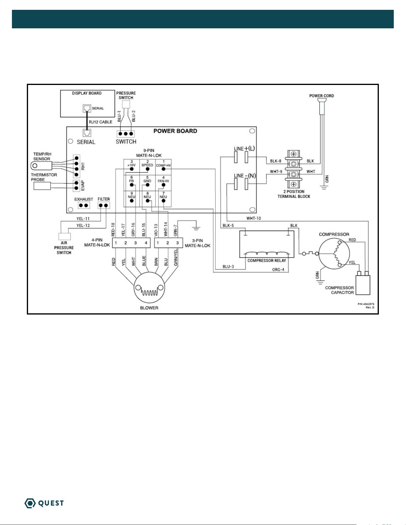
WIRING DIAGRAM OF THE QUEST 225 DEHUMIDIFIER

26
QUEST 225 INSTALLATION, OPERATION AND MAINTENANCE INSTRUCTIONS
QUESTCLIMATE.COM(877) 420-1330
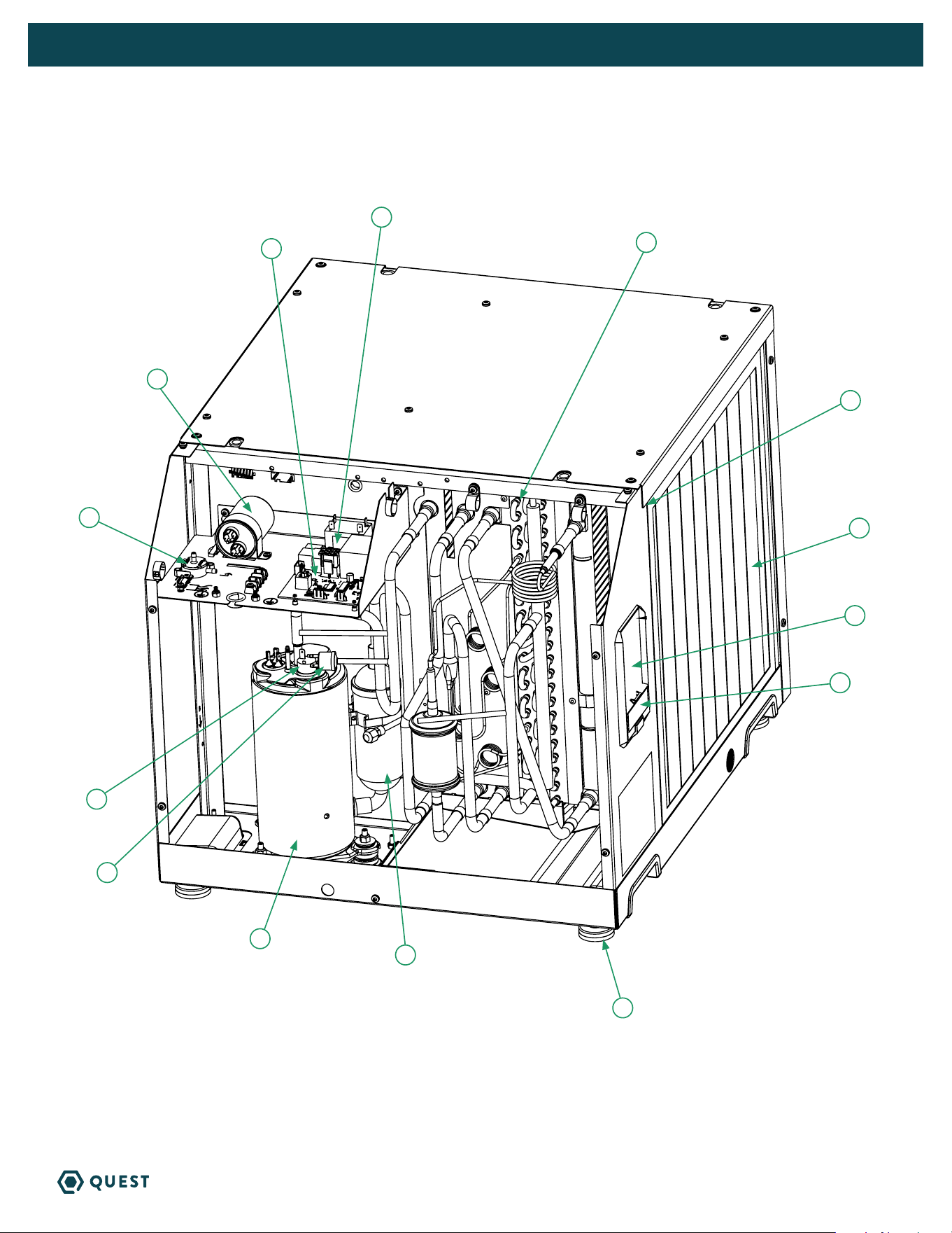
SERVICE PARTS LIST FOR QUEST 225
OPTIONAL PARTS LIST
Item Part No Qty Description
1 4042787 1 MERV-13 Air Filter
2x18x18”
2 4026221 4 Leveling Foot
3 4042468 1 Filter/Drier
4 4042849 1 Compressor
5 4042800 1 Coil Cassette Assembly
6 4039988 1 Compressor Overload
7 4042845 1 Impeller Assembly*
8 4035949-10 1 Capacitor, Run, 45 MFD
Item Part No Qty Description
9 4042467 1 Relay, SPST 220V, 25A
10 4034716-03 1 Thermistor Probe*
11 4042061 1 Temp RH Sensor
12 4043292 1 High Pressure Switch
13 4042903 1 Pressure Diff Switch
14 4041909 1 Digital Display Board
15 4042291 1 Control Board
16 4042009 1 Cover, UI, 24VAC
Part No Qty Description
4022220 1 Pump Kit (110-120V)
4043235 1 Supply & Return Duct Kit
Part No Qty Description
4028531 1 DEH 3000R Control, Remote
* Not pictured
27
QUEST 225 INSTALLATION, OPERATION AND MAINTENANCE INSTRUCTIONS
QUESTCLIMATE.COM(877) 420-1330
2
4
13
8
15
3
6
12
1
14
11
16
5
9
28
QUEST 225 INSTALLATION, OPERATION AND MAINTENANCE INSTRUCTIONS
QUESTCLIMATE.COM(877) 420-1330
QUEST 225 DEHUMIDIFIER LIMITED WARRANTY
WHO IS COVERED: This warranty extends only to the original end-user of the Quest 225 dehumidifier, and may
not be assigned or transferred.
FIRST YEAR WARRANTY: Therma-Stor LLC warrants that, for one (1) year the Quest 225 dehumidifier will operate
free from any defects in materials and workmanship, or Therma-Stor LLC will, at its option, repair or replace the
defective part(s), free of any charge.
SECOND THROUGH FIFTH YEAR WARRANTY: Therma-Stor LLC further warrants that for a period of five (5)
years, the condenser, evaporator, and compressor of the Quest 225 Dehumidifier dehumidifier will operate free
of any defects in material or workmanship, or Therma-Stor LLC, at its option, will repair or replace the defective
part(s), provided that all labor and transportation charges for the part(s) shall be borne by the end-user.
END-USER RESPONSIBILITIES: Warranty service must be performed by a Servicer authorized by Therma-Stor
LLC. If the end-user is unable to locate or obtain warranty service from an authorized Servicer, he should call
Therma-Stor LLC at the above number and ask for the Therma-Stor LLC Service Department, which will then
arrange for covered warranty service. Warranty service will be performed during normal working hours.
The End-user must present proof of purchase (lease) upon request, by use of the warranty card or other
reasonable and reliable means. The end-user is responsible for normal care. This warranty does not cover
any defect, malfunction, etc. resulting from misuse, abuse, lack of normal care, corrosion, freezing, tampering,
modification, unauthorized or improper repair or installation, accident, acts of nature or any other cause beyond
Therma-Stor LLC's reasonable control.
LIMITATIONS AND EXCLUSIONS: If any Quest 225 Dehumidifier part is repaired or replaced, the new part shall
be warranted for only the remainder of the original warranty period applicable thereto (but all warranty periods
will be extended by the period of time, if any, that the Quest 225 Dehumidifier is out of service while awaiting
covered warranty service).
UPON THE EXPIRATION OF THE WRITTEN WARRANTY APPLICABLE TO THE QUEST DEHUMIDIFIER OR ANY PART THEREOF, ALL OTHER
WARRANTIES IMPLIED BY LAW, INCLUDING MERCHANTABILITY AND FITNESS FOR A PARTICULAR PURPOSE, SHALL ALSO EXPIRE. ALL
WARRANTIES MADE BY THERMA-STOR LLC ARE SET FORTH HEREIN, AND NO CLAIM MAY BE MADE AGAINST THERMA-STOR LLC BASED
ON ANY ORAL WARRANTY. IN NO EVENT SHALL THERMA-STOR LLC, IN CONNECTION WITH THE SALE, INSTALLATION, USE, REPAIR OR
REPLACEMENT OF ANY QUEST DEHUMIDIFIER OR PART THEREOF BE LIABLE UNDER ANY LEGAL THEORY FOR ANY SPECIAL, INDIRECT
OR CONSEQUENTIAL DAMAGES INCLUDING WITHOUT LIMITATION WATER DAMAGE (THE END-USER SHOULD TAKE PRECAUTIONS AGAINST
SAME), LOST PROFITS, DELAY, OR LOSS OF USE OR DAMAGE TO ANY REAL OR PERSONAL PROPERTY.
Some states do not allow limitations on how long an implied warranty lasts, and some do not allow the exclusion
or limitation of incidental or consequential damages, so one or both of these limitation may not apply to you.
LEGAL RIGHTS: This warranty gives you specific legal rights, and you may also have other rights which vary from
state to state.
REGISTER YOUR NEW DEHUMIDIFIER
using the serial number and part number at
www.thermastor.com/registration
or scan code, right.
WARRANTOR:
Therma-Stor LLC
4201 Lien Rd
Madison, WI 53704
Telephone: 1-800-533-7533
IMPORTANT WARRANTY INFORMATION
DO NOT DISCARD