READ AND SAVE THESE INSTRUCTIONS
FOR A COMPLETE MANUAL, GO TO QUESTCLIMATE.COM/MANUALS
This guide is provided to acquaint you with the dehumidifier so that installation, operation and maintenance can proceed
successfully. Ultimate satisfaction depends on the quality of installation and a thorough understanding of this equipment.
The dehumidifier is built around tested engineering principles and has passed a thorough inspection for quality of
workmanship and function.
QUICK START INSTRUCTIONS
QUEST
100
QUESTCLIMATE.COM / (877) 420-1330 TS-2009 06/23 REV C
For complete product
information, scan here
:
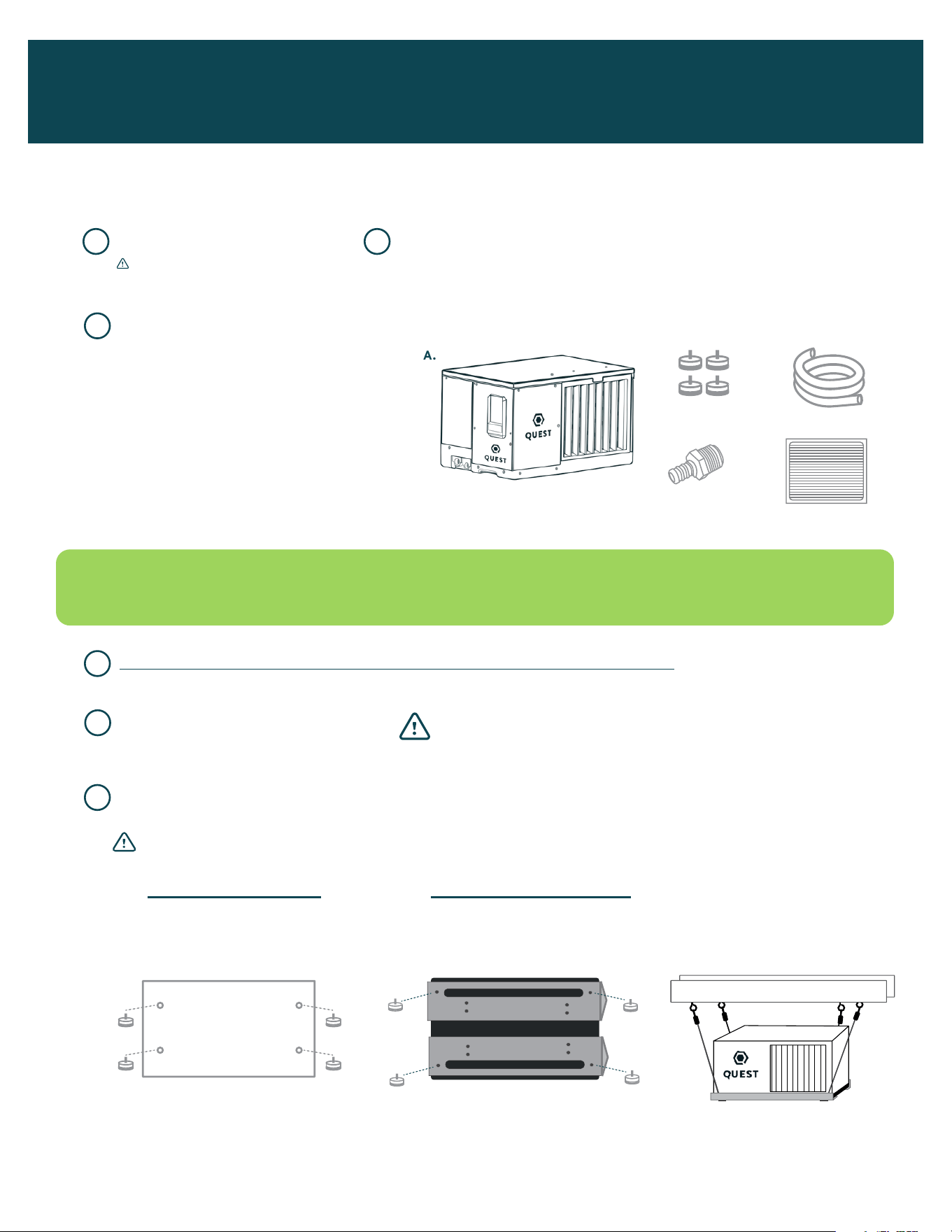
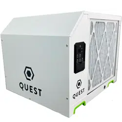
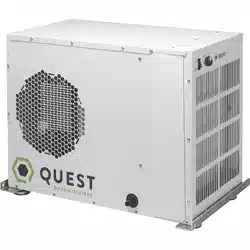
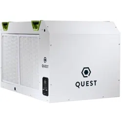
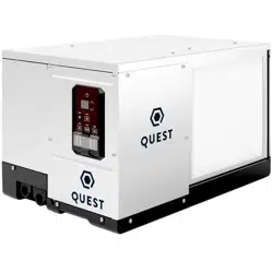
A. Dehumidifier (1)
B. Leveling Feet (4)
C. Drain Hose (1)
D. Drain Adapter (1)
3/4” NPT PVC to 5/8” Hose Barb
E. Filter (1)
1” x 12” x 14”
A. IF YOU PLACE ON FLOOR:
Attach leveling feet. Place
rivnut plugs over hang kit
holes on top of unit.
B. IF YOU HANG DEHUMIDIFIER:
USE 2 BRACKETS PER UNIT.
*Brackets sold separately.
EXAMPLE OF
HANGING OPTION:
UNPACK BOX REGISTER WARRANTY AT THERMASTOR.COM/REGISTRATION
CHECK THAT YOU HAVE ALL PARTS:
READ ALL REMAINING STEPS AND WARNINGS BEFORE CONTINUING
CHOOSE WHETHER TO PLACE ON FLOOR OR HANG DEHUMIDIFIER
DECIDE WHERE TO PLACE
UNIT IN THE ROOM
QUEST DEHUMIDIFIERS CAN RUN WITHOUT ADDITIONAL ACCESSORIES. DEPENDING ON INSTALLATION,
YOU MAY REQUIRE ADDITIONAL PARTS. SEE STEP 13 FOR ADDITIONAL INFORMATION.
1 2
3
4
6
5
I
I
I
I
I
I
I
I
I
I
I
I
I
I
I
H
U
M
I
D
N
O
R
M
A
L
D
R
I
E
R
OFFON
BEFORE TURNING ON UNIT:
1. CUT AND REMOVE ZIP TIE
2. PLUG HOLES USING
INCLUDED PLUGS
COM
FAN
24V
DEHU
*
DMPR
COM
FAN
24V
DEHU
*
DMPR
24V AC
COMP FAN
HONEYWELL REMOTE HUMIDISTAT
WIRING DIAGRAM
QUEST DEH 3000R CONTROL
WIRING DIAGRAM
I
I
I
I
I
I
I
I
I
I
I
I
I
I
I
H
U
M
I
D
N
O
R
M
A
L
D
R
I
E
R
OFFON
BEFORE TURNING ON UNIT:
1. CUT AND REMOVE ZIP TIE
2. PLUG HOLES USING
INCLUDED PLUGS
COM
FAN
24V
DEHU
*
DMPR
COM
FAN
24V
DEHU
*
DMPR
24V AC
COMP FAN
HONEYWELL REMOTE HUMIDISTAT
WIRING DIAGRAM
QUEST DEH 3000R CONTROL
WIRING DIAGRAM
I
I
I
I
I
I
I
I
I
I
I
I
I
I
I
H
U
M
I
D
N
O
R
M
A
L
D
R
I
E
R
OFFON
BEFORE TURNING ON UNIT:
1. CUT AND REMOVE ZIP TIE
2. PLUG HOLES USING
INCLUDED PLUGS
COM
FAN
24V
DEHU
*
DMPR
COM
FAN
24V
DEHU
*
DMPR
24V AC
COMP FAN
HONEYWELL REMOTE HUMIDISTAT
WIRING DIAGRAM
QUEST DEH 3000R CONTROL
WIRING DIAGRAM
A.
D.
B.
E.
C.
I
I
I
I
I
I
I
I
I
I
I
I
I
I
I
H
U
M
I
D
N
O
R
M
A
L
D
R
I
E
R
OFFON
BEFORE TURNING ON UNIT:
1. CUT AND REMOVE ZIP TIE
2. PLUG HOLES USING
INCLUDED PLUGS
COM
FAN
24V
DEHU
*
DMPR
COM
FAN
24V
DEHU
*
DMPR
24V AC
COMP FAN
HONEYWELL REMOTE HUMIDISTAT
WIRING DIAGRAM
QUEST DEH 3000R CONTROL
WIRING DIAGRAM
ASSEMBLY & INSTALLATION
Thanks for purchasing a Quest 100 dehumidifier. For a complete manual, visit QuestClimate.com/manuals.
Please follow these steps to successfully assemble and install your new dehumidifier.
4036668
IMPORTANT! RETAIN SHEET OF CARDBOARD
UNDER MACHINE TO PREVENT SCRATCHING.
WARNING! Don’t block airflow inlet. Outlet must be at least 24 inches
from walls and other obstructions. If there is not enough clearance there
will be a restriction in airflow and performance.
WARNING! Interal stops limit feet height. Do not tighten feet beyond the resistance provided by stops.
*Recommend 4” off ground.
See manual for details.
*Leveling feet hold bracket in place.
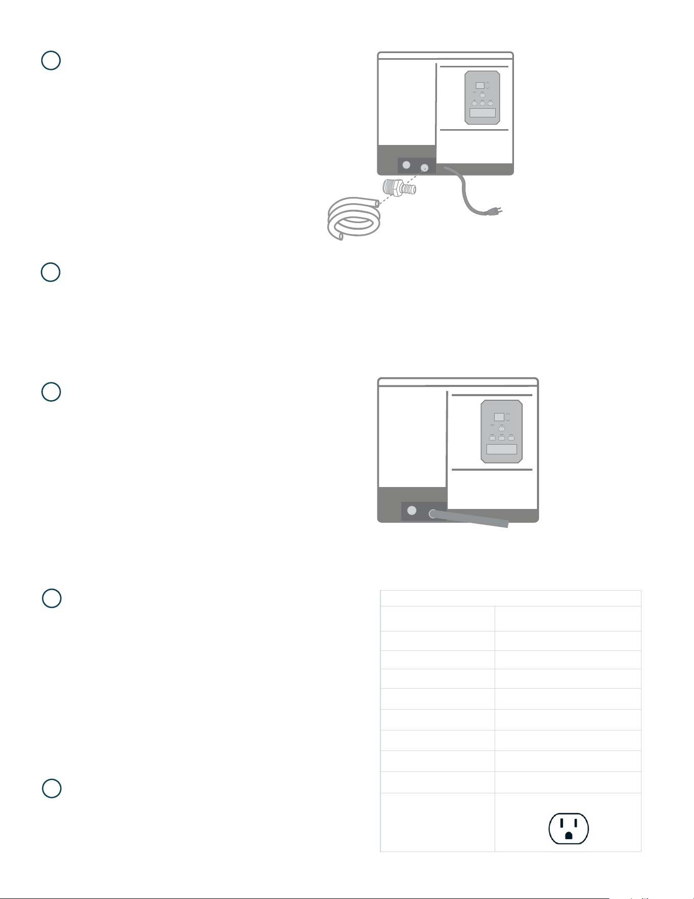
A. If you need water to travel a further distance,
see Section 13 on how to order a pump kit.
B. See manual for more details.
INSERT DRAIN ADAPTER AND ATTACH
DRAIN HOSE* TO PRIMARY DRAIN PORT.
(Located lower, nearest to cord.)
OUTPUT TO DRAIN OR BUCKET.
INSTALL NORMALLY-CLOSED FLOAT
SWITCH TO SECONDARY DRAIN PORT FOR
OVERLFLOW PROTECTION (OPTIONAL).
See manual for details.
*
7
*
* You can use provided hose, or
install PVC to route water.
9
8
PLUG IN UNIT TO DEDICATED 15 AMP CIRCUIT.
VERIFY WALL OUTLET IS CORRECT
VOLTAGE AND AMPERAGE.
10
11
Specifications @ 80 F / 60% RH
UNIT
QUEST 100
4041870
Blower 280 CFM @ 0.0’WG
Supply Voltage (VAC) 120V
Current Draw (Amps) 5.0
Operating Temperature 56 F - 95 F
Air Filter (MERV-13) Size: 12” x 14” x 1”
Weight (lbs) 60
Capacity (Pints/Day) 100
Efficiency (Pints/kWh) 7. 5
Power Cord
9’, 115 VAC, NEMA 5-15P
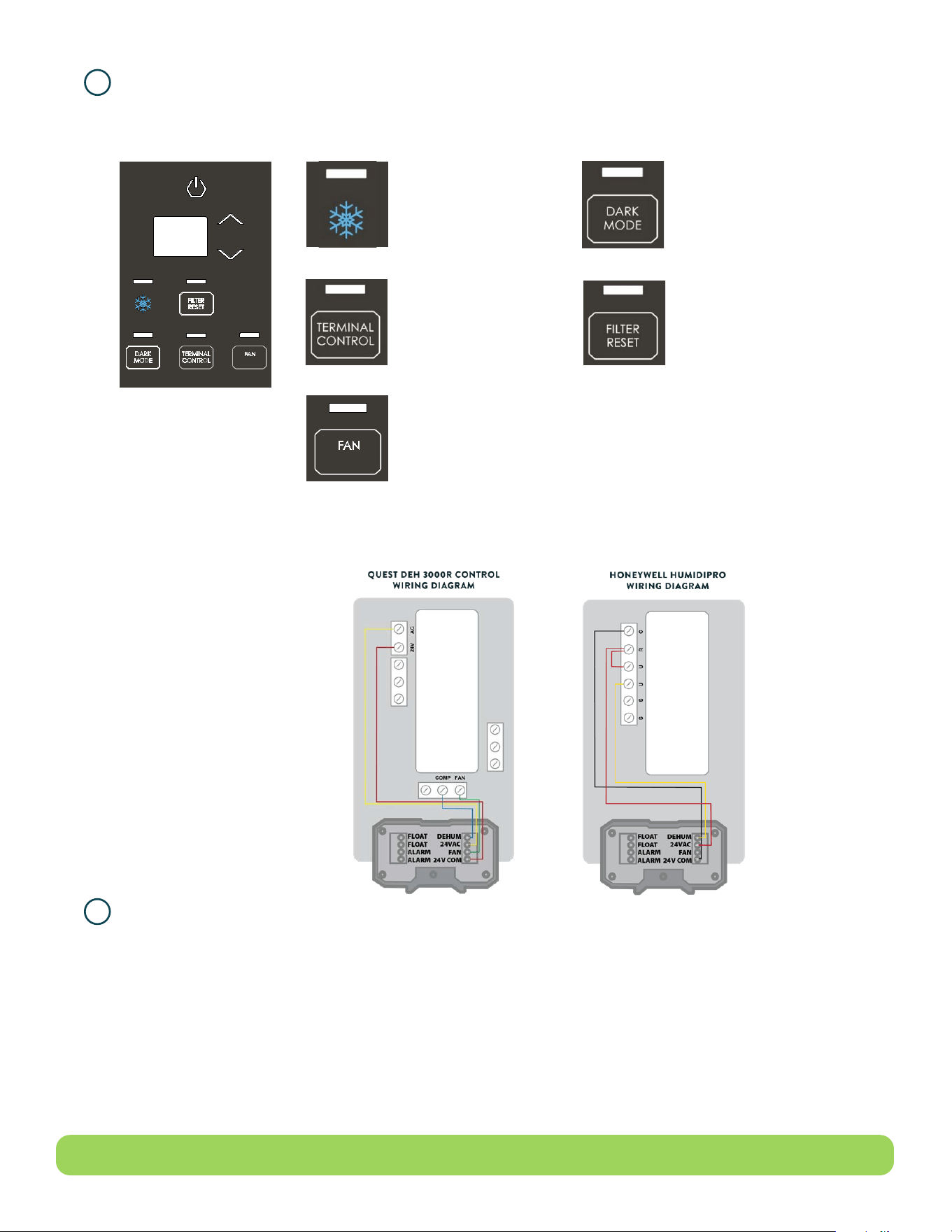
A. Use the up and down arrows on the control board to set desired relative humidity. 50% is recommended.
B. Press and release terminal control button until light is not illuminated for control board.
C. If you prefer external controls, you can source any 24v controller, or see section 13 below on how to order
from Quest.
ADJUST HUMIDITY.
12
13
ACCESSORIES
A. Replacement Filter: Change filters each grow cycle for maximum performance.
B. Brackets: Recommended for hanging the dehumidifier overhead.
C. Pump Kit: Allows for draining and transferring water when the unit is not hard plumbed or near a drain.
D. External Control: Ideal for overhead installation or with duct work.
E. Intake Duct Kit: Dehumidifies air directly from a remote area.
F. Exhaust Duct Kit: Provides dehumidified air directly to remote area.
NEED HELP? GIVE US A CALL (877) 420-1330
To purchase additional accessories for your system, visit
QuestClimate.com/Product-Category/Accessories/All-Accessories/
DEFROST LIGHT
The light over the snowflake will
light up when defrost is occurring
(ice is detected on coils).
Temperature is too cold and/or
conditions are too dry.
DARK MODE
Pressing the dark mode button will turn off
all lighting on the control. Dark Mode will last
until any button on the control is pressed.
Once a button is pressed, the control will
light up for 10 seconds following last button
push. When the control is lit up, pressing the
Dark Mode button will turn off Dark Mode.
TERMINAL CONTROL
This must be activated when
an external control is used
to control RH. When terminal
control is active, the internal RH
sensor is disabled.
FAN
Pressing the Fan button alternates
between 3 fan modes.
Hi(gh)- Increased fan speed to be used
exclusively in ducted applications.
Au(to)- Default fan speed.
Lo(w)- Decreased fan speed that lowers the
volume and performance of the unit.
FILTER RESET
Filter reset button will light up after the
fan has been running for 2,000 hours
indicating that the filter must be changed.

WARRANTOR: THERMA-STOR LLC, 4201 LIEN RD., MADISON, WI 53704 1-800-533-7533
QUEST 100 DEHUMIDIFIER
WHO IS COVERED: This warranty extends only to the original end-user of the Quest dehumidifier, and may not be assigned or transferred.
FIRST YEAR WARRANTY: Therma-Stor LLC warrants that for one (1) year the Quest dehumidifier will operate free from any defects in materials and workmanship, or
Therma-Stor LLC will, at its option, repair or replace the defective part(s), free of any charge.
SECOND THROUGH FIFTH YEAR WARRANTY: Therma-Stor LLC further warrants that for a period of five (5) years, the condenser, evaporator and compressor of the
Quest dehumidifier will operate free of any defects in material or workmanship, or Therma-Stor LLC, at its option, will repair or replace the defective part(s), provided
that all labor and transportation charges for the part(s) shall be borne by the end-user.
END-USER RESPONSIBILITIES: Warranty service must be performed by a Servicer authorized by Therma-Stor LLC. If the end-user is unable to locate or obtain warranty
service from an authorized Servicer, he should call Therma-Stor LLC at the above number and ask for the Therma-Stor LLC Service Department, which will then arrange
for covered warranty service. Warranty service will be performed during normal working hours. The end-user must present proof of purchase (lease) upon request, by
use of the warranty card or other reasonable and reliable means. The end-user is responsible for normal care. This warranty does not cover any defect, malfunction, etc.,
resulting from misuse, abuse, lack of normal care, corrosion, freezing, tampering, modification, unauthorized or improper repair or installation, accident, acts of nature
or any other cause beyond Therma-Stor LLC’s reasonable control.
LIMITATIONS AND EXCLUSIONS: If any Quest dehumidifier part is repaired or replaced, the new part shall be warranted for only the remainder of the original warranty
period applicable thereto (but all warranty periods will be extended by the period of time, if any, that the Quest dehumidifier is out of service while awaiting covered
warranty service).
UPON THE EXPIRATION OF THE WRITTEN WARRANTY APPLICABLE TO THE QUEST DEHUMIDIFIER OR ANY PART THEREOF, ALL OTHER WARRANTIES IMPLIED BY LAW, INCLUDING MERCHANTABILITY AND
FITNESS FOR A PARTICULAR PURPOSE, SHALL ALSO EXPIRE. ALL WARRANTIES MADE BY THERMA-STOR LLC ARE SET FORTH HEREIN, AND NO CLAIM MAY BE MADE AGAINST THERMA-STOR LLC BASED ON
ANY ORAL WARRANTY. IN NO EVENT SHALL THERMA-STOR LLC, IN CONNECTION WITH THE SALE, INSTALLATION, USE, REPAIR OR REPLACEMENT OF ANY QUEST DEHUMIDIFIER OR PART THEREOF BE LIABLE
UNDER ANY LEGAL THEORY FOR ANY SPECIAL, INDIRECT OR CONSEQUENTIAL DAMAGES INCLUDING WITHOUT LIMITATION WATER DAMAGE (THE END-USER SHOULD TAKE PRECAUTIONS AGAINST SAME), LOST
PROFITS, DELAY OR LOSS OF USE OR DAMAGE TO ANY REAL OR PERSONAL PROPERTY. SOME STATES DO NOT ALLOW LIMITATIONS ON HOW LONG AN IMPLIED WARRANTY LASTS, AND SOME DO NOT ALLOW THE
EXCLUSION OR LIMITATION OF INCIDENTAL OR CONSEQUENTIAL DAMAGES, SO ONE OR BOTH OF THESE LIMITATIONS MAY NOT APPLY TO YOU.
LEGAL RIGHTS: This warranty gives you specific legal rights, and you may also have other rights which vary from state to state.
READ AND SAVE THESE INSTRUCTIONS
• The device is designed to be installed INDOORS IN A SPACE THAT IS PROTECTED FROM RAIN AND FLOODING.
• Install the unit with space to access the back or side panels for maintenance and service. DO NOT INSTALL UNIT WITH THE SERVICE PANELS
INACCESSIBLE.
• Avoid directing the discharge air at people, or over the water in pool areas.
• If used near a pool, spa or water; be certain there is NO chance the unit could fall into the water, be splashed and that it is plugged into an
outlet that is a GROUND FAULT INTERRUPT protected circuit.
• DO NOT use the device as a bench or table.
• DO NOT place the device directly on structural members. Provide vibration isolation in order to minimize operational vibration and/or noise.
• A drain pan MUST be placed under the unit if installed above a living area or above an area where water leakage could cause damage
• Never operate a unit with a damaged power cord. If the power cord is damaged it must be replaced by the manufacturer, its service agent,
or similarly qualified person in order to avoid a hazard.
• Make all electrical connections in accordance with the current edition of the NEC ANSI/NFPA 70 and any national and local codes or
ordinances that may apply.
• Do not obstruct the air intake and exhaust. Maintain a .3 m (1 ft) clearance around the air intake and exhaust.
• This appliance is not intended for use by persons (including children) with reduced physical, sensory or mental capabilities, or lack of
experience and knowledge, unless they have been given supervision or instruction concerning use of the appliance by a person responsible
for their safety. Children should be supervised to ensure that they do not play with the appliance.
LIMITED WARRANTY
REGISTER YOUR NEW PRODUCT
using the serial number and part number at
www.thermastor.com/registration
or scan code to the right
SERIAL NUMBER
PART NUMBER

FOR INTERNAL USE ONLY