
HELA 2050R Platinum
HELA Series
Cybenetics Platinum 2050W ATX 3.0 & PCIe 5.0
Fully Modular ATX Power Supply
Supports 12VHPWR PCIe connector with ATX 3.0 and PCIe Gen 5 standard
High efficiency with Cybenetics Platinum certification
Compact and high density design with a depth of 180mm for easy integration
Built-in MCU semi-fanless mode to achieve optimized cooling performance
2050W 24/7 continuous power output with 50℃ operating temperature
SPECIFICATION
SilverStone HELA Series
HELA 2050R Platinum
SST-HA2050R-PM
ATX Switching Power Supply
Cybenetics Platinum efficiency certified.
2050W
This specification defines ATX Version 3.0 & EPS12V Ver. 2.92 multiple output
switching power supply. The parameters of this supply are defined in this
specification for Family using. This specification defines max continuous output
at 1350W with 100 to 240Vac input, 1650W with 115 to 240Vac input and 2050W
with 200V to 240Vac input power supply with five outputs;+3.3V,+5V,+12V,-12V
and +5VSB.The +5V standby voltage, remote on/off control, full range line input
capability. An IEC connector is provided on the external face for AC input to the
power supply. The power supply contains fans for cooling, while meeting acoustic
requirements.
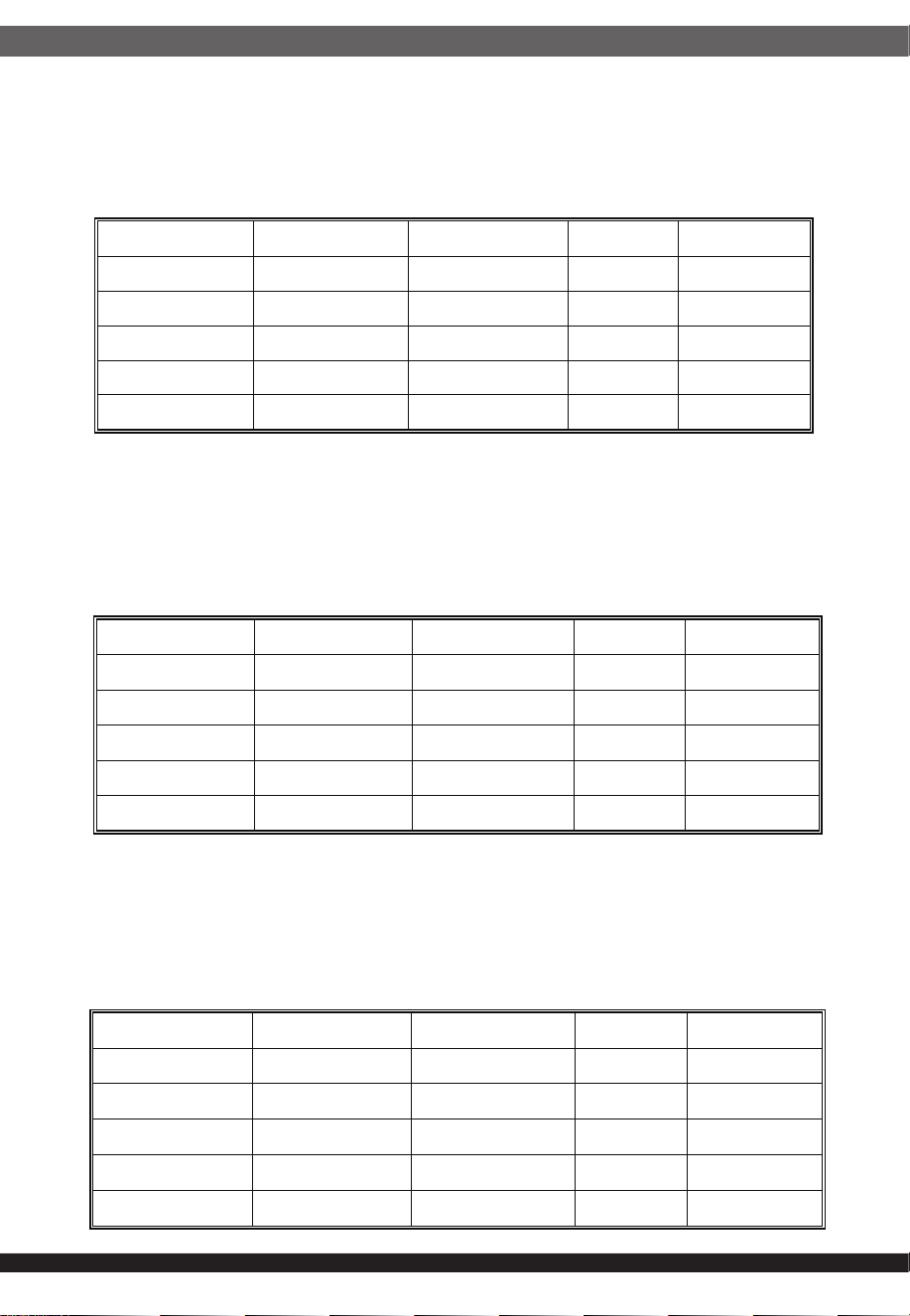
The input voltage, current, and frequency requirements for continuous operation
are stated show in Table 1.
Table 1.
01
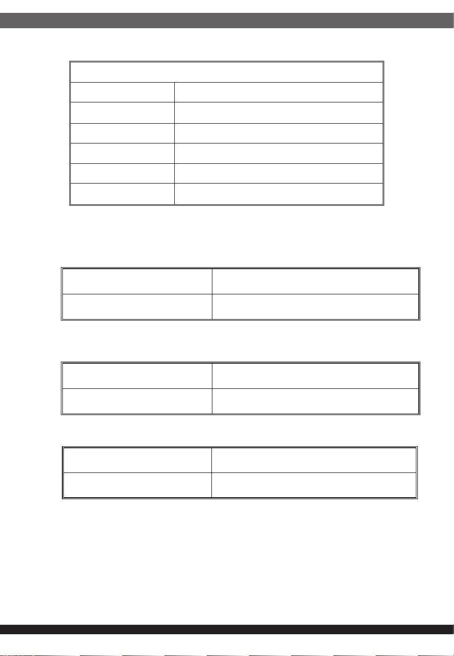
1.1 AC input requirements:
1. AC input characteristics:
Parameter Min Nom Max Unit
Vin 90 100 --- 240 264 VACrms
Vin Frequency 47 60 --- 50 63 Hz
Iin(1350W)
15 --- 7.5 A
1.2 AC inrush current(cold start):
2.1 Output voltage regulation Requirements:
The power supply must meet inrush requirements for any rated AC voltage,
during turn on at any phase. of AC voltage, during a single cycle AC dropout
condition, during repetitive ON/OFF cycling of AC, and over the specified
temperature range .The peak inrush current shall be less than the ratings of
its critical components (including input fuse, bulk rectifiers, and surge limiting
device).
Note: Enhance Design Internal Standard: Vac input 115V 50A MAX,
Vac input 230V 100A MAX.
The power supply output voltage must stay within the following voltage limits
shown in Table2 when operating at steady state.
Table2
2. DC Output characteristics:
02
Parameter Min Nom Max Unit
Vin 103 115 --- 240 264 VACrms
Vin Frequency 47 60 --- 50 63 Hz
Iin(1650W)
15 --- 9 A
Parameter Min Nom Max Unit
Vin 180 200 --- 240 264 VACrms
Vin Frequency 47 50 63 Hz
Iin(2050W)
13 A
Parameter Range Min Nom. Max Unit
+3.3V ±3% +3.20 +3.30 +3.40 Volts
+5V ±3% +4.85 +5.0 +5.15 Volts
+12V +5%/-7% +11.20 +12.0 +12.36 Volts
-12V ±5% -11.4 -12.0 -12.6 Volts
+5VSB ±5% +4.75 +5.0 +5.25 Volts
03
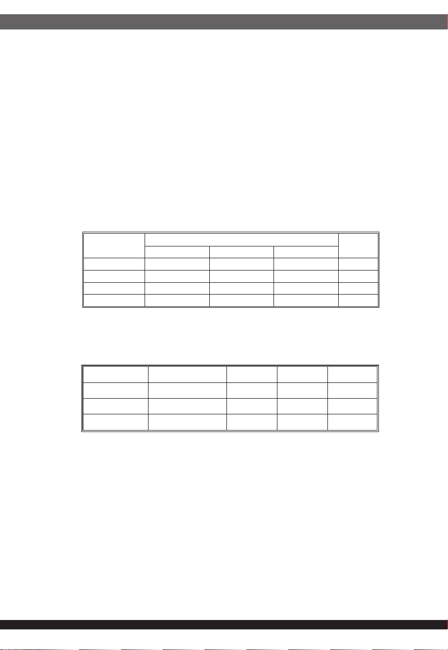
2.2 Output Current Requirements:
The power supply output current following shown in Table3.
Notes:
1. The maximum continuous average DC output power shall not exceed 1350W.
2. Maximum continuous combined load on +3.3V and +5V outputs shall not
exceed 120W.
3. The 12VHPWR Max load shall not exceed 50A(600W)
Notes:
1. The maximum continuous average DC output power shall not exceed 1650W.
2. Maximum continuous combined load on +3.3V and +5V outputs shall not
exceed 120W.
3. The 12VHPWR Max load shall not exceed 50A(600W).
Table3
1350W
1650W
2050W
Parameter Min Max Peak Unit
+3.3V 0 25 Amps
+5V 0 22 Amps
+12V 0 112 Amps
-12V 0 0.3 Amps
+5VSB 0 3 Amps
Parameter Min Max Peak Unit
+3.3V 0 25 Amps
+5V 0 22 Amps
+12V 0 137 Amps
-12V 0 0.3 Amps
+5VSB 0 3 Amps
Parameter Min Max Peak Unit
+3.3V 0 25 Amps
+5V 0 22 Amps
+12V 0 170 Amps
-12V 0 0.3 Amps
+5VSB 0 3 Amps
Notes:
1. The maximum continuous average DC output power shall not exceed 2050W.
2. Maximum continuous combined load on +3.3V and +5V outputs shall not
exceed 120W.
3. The 12VHPWR Max load shall not exceed 50A(600W).
04
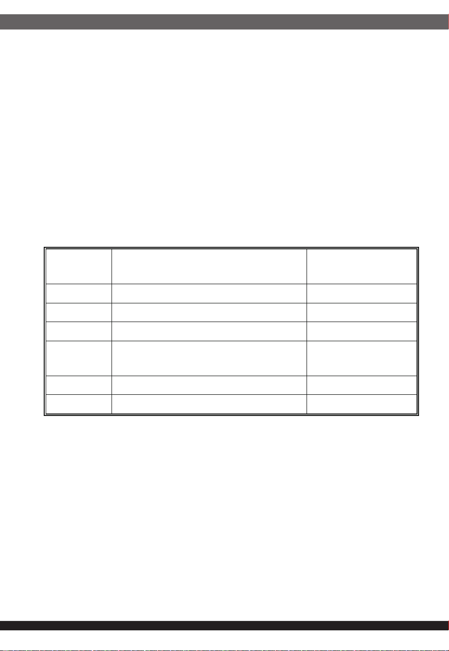
Table 4 summarizes the expected output transient step sizes for each output.
+12V Min load 1A for 0%~85% load.
The +3.3V&+5V transient load slew rate is = 1.0 A/μs. The +12V transient load
slew rate is = 5.0 A/μs.
NOTES:
1. For example, for a rated +5 VDC output of 14A, the transient step would be
30% x 14 A = 4.2 A.
2. Output voltages should remain within the regulation limits of Section 2.1,
and the power supply should stable when subjected to load transients per
Table 3. from any steady state load, including any or all of the following
conditions:
3. Simultaneous load steps on the +12 VDC, +5 VDC, and +3.3 VDC outputs
(all steps occurring in the same direction)
4. Load-changing repetition rate of 50 Hz to 10 kHz
5. AC input range per Section 1.1 and Capacitive loading per Table 8.
6. The +12V min start load is 5Amin at dynamic load response test.
Table4
2.3 Output Transient Response:
Parameter
Maximum Step Size (% of rated
output amps)
Maximum Step Size
(A)
+3.3V 40% load
+5V 40% load
+12V 85% load 1A
+12V
(12VHPWR)
Steps from 100%→300%
30%→100%
-12V 0.1A
+5VSB 0.5A
2.5.1 In the 115Vac/60Hz input voltage the power supply efficiency is more
than 92%.
Table6 A
1350W,1650W:
Note: There is a 0.5% tolerance in mass production
05
2.5 Efficiency:
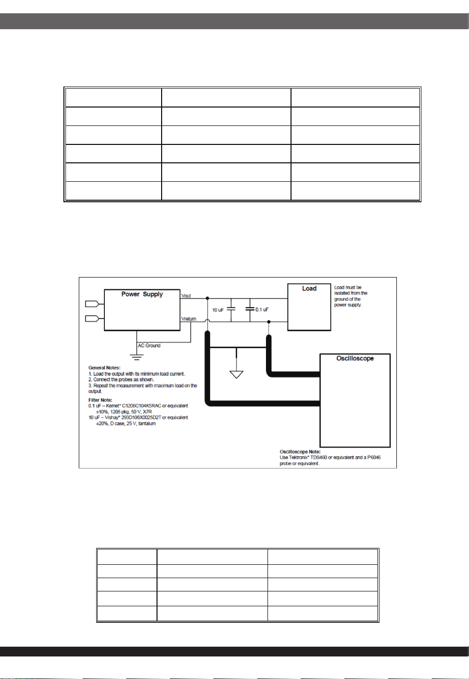
2.4 Output Ripple and Noise:
Note:
This is measured over a bandwidth of 10Hz to 20MHz at the power supply output
connector. A 10μF electrolytic capacitor in a parallel with a 0.1μF ceramic capacitor
is placed at the point of measurement.Differential noise test setup
Table5
Figure 1
Output
Ripple and Noise Unit
+3.3V
30
mVp-p
+5V
30
mVp-p
+12V
60
mVp-p
-12V
60
mVp-p
+5VSB
30
mVp-p
Load
Efficiency(%)
Power Factor
2% 60 --
20% 90 --
50%
92 >0.95
100%
89 >0.95
2.6 Remote on/off control
2.7 Overshoot:
2.8 Capacitance Loading
The overshoot of the DC output voltage caused by switching AC power or switch
PSON# should be less than 10% of the normal output, and no reverse polarity
voltage should be produced.
The power supply shall be stable and meet all requirements with the following
capacitive loading ranges.
When the logic level "PS-ON" is low, the DC outputs are to be enabled.
When the logic level is high or open collector, the DC outputs are to be disabled.
06
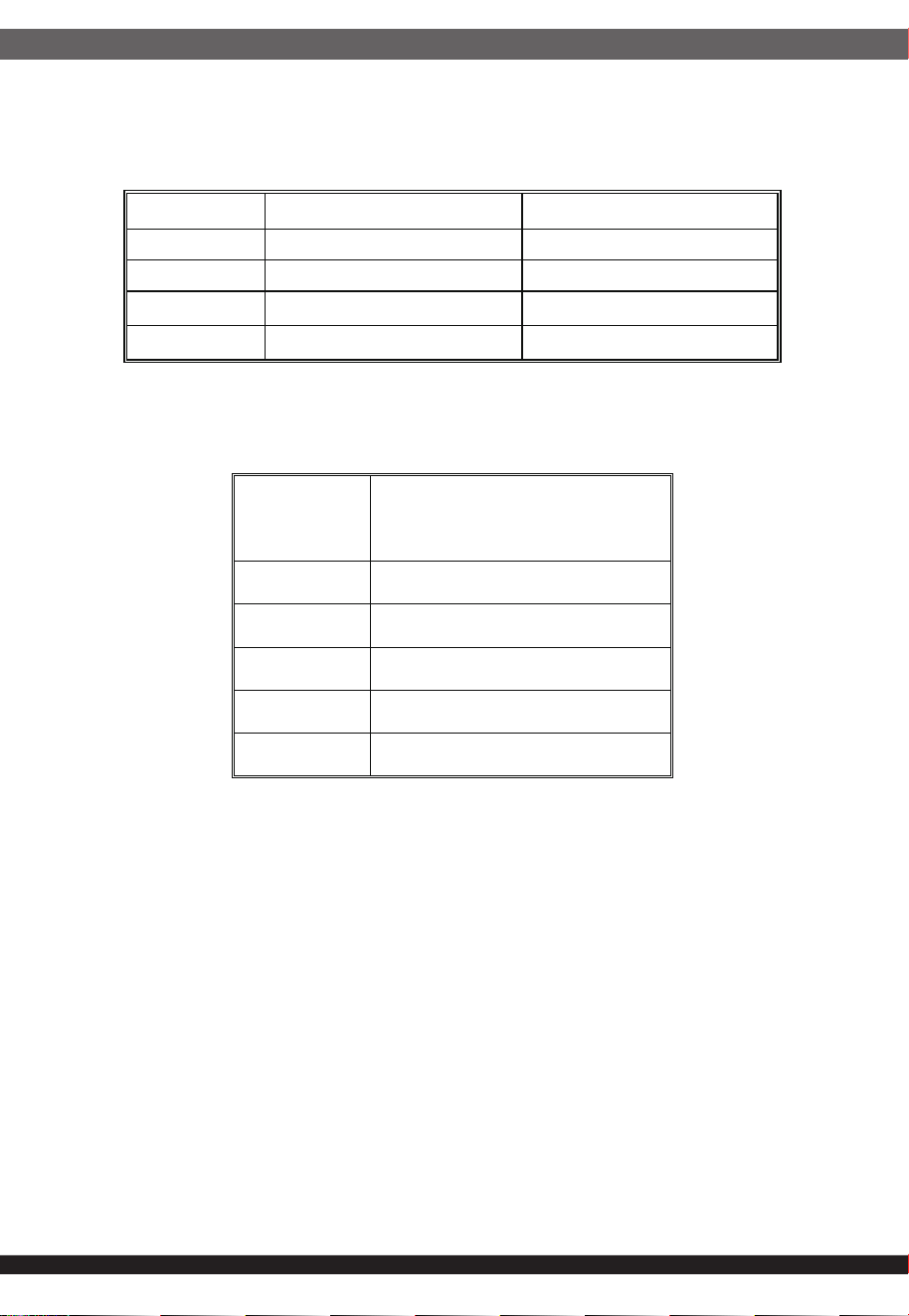
2.5.2 In the 230Vac/60Hz input voltage the power supply efficiency is more
than 94%.
2.5.3 ERP 5VSB Efficiency
Table6 B
Table7
2050W
Note: There is a 0.5% tolerance in mass production
Load
Efficiency(%)
Power Factor
2% 60 --
20% 92 --
50%
94 >0.95
100%
90 >0.95
+5VSB LOAD
Efficiency target
(both 110V and 230V input)
3A 75%
1.5A 75%
1A 75%
0.55A 75%
45mA 45%
Forced air cooling.
Table10
Table8
Table11
07
3.2 Shipping and Storage:
3.3 Altitude:
3.4 Cooling mode:
Non-operating 0.01 g²/Hz at 5 Hz, sloping to 0.02 g²/Hz at 20 Hz, and
maintaining 0.02 g²/Hz from 20 Hz to 500 Hz. The area under the PSD curve
is 3.13 grams.
The duration shall be 10 minutes per axis for all three axes on all samples.
3.5 Random Vibration:
Temperature
-40℃ ~ 70℃
Relave Humidity 5% to 95%,non-condensing
Operang ≤2000m
Storage ≤3000m
Capacive Loading Condions
Output
Capacive Load (μF)
+3.3V
3,300
+5V
3,300
+12V
3,300
-12V
3,30
+5VSB
3,300
3.1 Operation temperature:
Table9
3.Environment:
Temperature 0 to 50ƫ
ƫ
Relave Humidity 5% to 85%,on-condensing
4.4 Short circuit protection:
An output short circuit is defined as any output impedance of less than 0.1
ohms. The power supply shall shut down and latch off for shorting the +3.3
VDC,+5 VDC,or+12VDC rails to return or any other rail. Shorts between main
output rails and +5VSB shall not cause any damage to the power supply.
The power supply shall either shut down and latch off or fold back for shorting
the negative rails.+5VSB must be capable of being shorted indefinitely, but
when the short is removed, the power supply shall recover automatically or by
cycling PS_ON#. The power supply shall be capable of withstanding a
continuous short-circuit to the output without damage or overstress to the unit
08
Due to overvoltage, over power and short circuit, the protection function of the
power supply circuit is self operated, and the power is self locked. There is no
output at that time. When these reasons are removed, the power is restored to
the normal output state when the power is restarted. (PSON# at least 1 second;
AC shutdown at least 4 seconds).
4. Protection:
The power supply will be shutdown and latch off when output power within
110~150% of rated DC output.
Note: Assurance machine can work at low voltage, full load won't damage
machine.
4.1 Over-power protection
Table12
Table15
4.2 Over voltage protection:
4.3 Under Voltage Protection
Output
Output voltage protecƟon point
Unit
Min Nom Max
+3.3V 3.76 4.2 4.3 V
+5V 5.74 6.3 7.0 V
+12V 13.4 15.0 15.6 V
+5VSB 5.74 6.3 7.0 V
Output Min. Typ. Max. Unit
+3.3V 2.8 2.9 3 Vdc
+5V 4.2 4.4 4.6 Vdc
+12V 10.3 10.6 11 Vdc
09
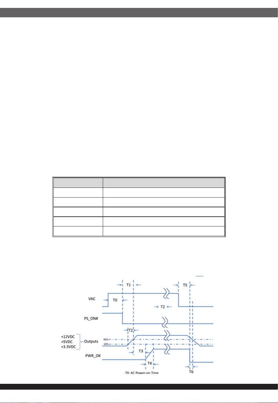
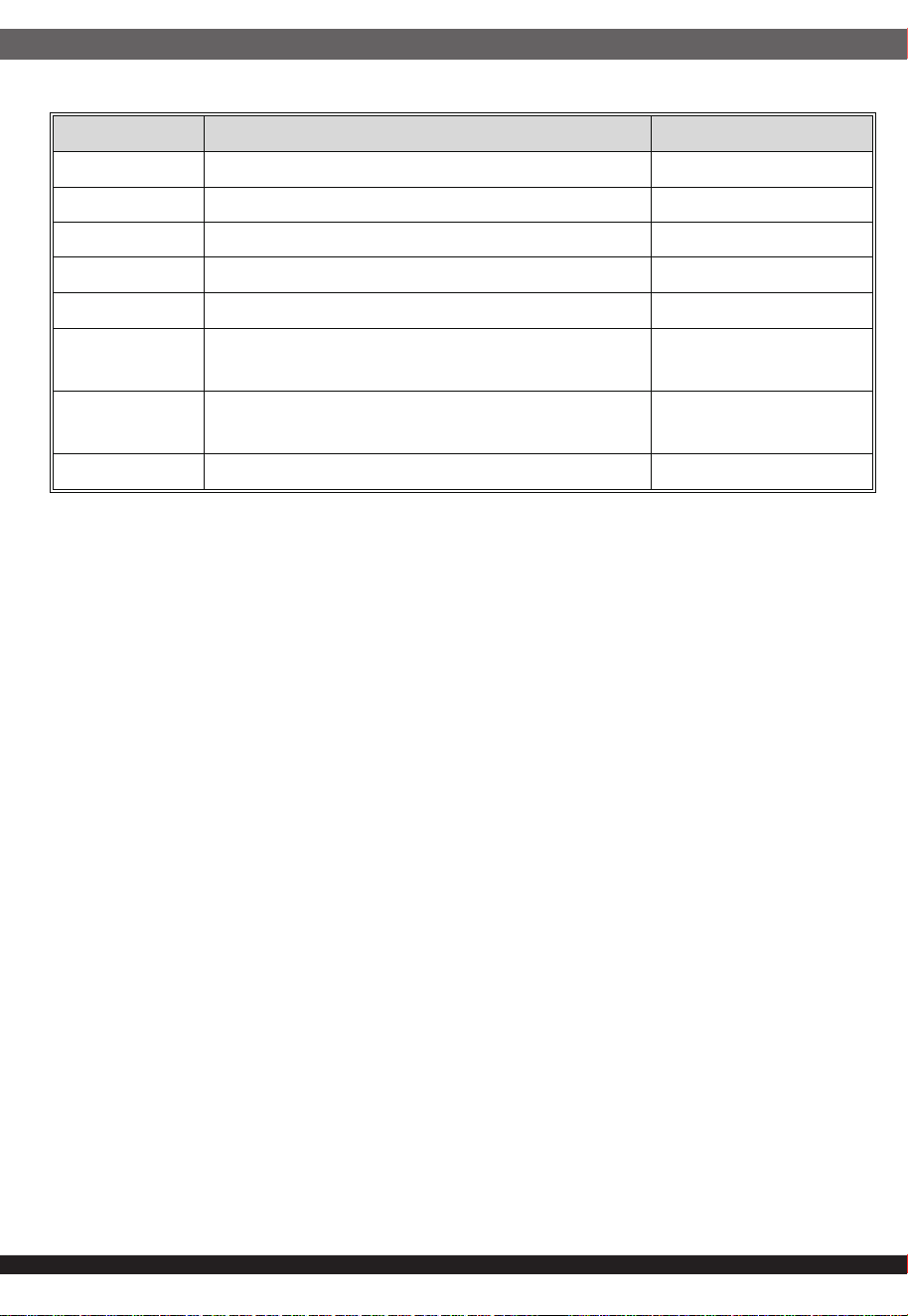
5. Power Supply Timing
5.1 Signal timing drawing
Figure 2 is a reference for signal timing for main power connector signals and rails.
Figure 2
4.5 Over Temperature Protection:
The power supply will be protected against over temperature conditions caused
by loss of fan cooling or excessive ambient temperature. In an OTP condition
the PSU will shutdown. When the power supply temperature drops to within
specified limits, the power supply shall Latch mode.
4.6 Over current protection
Table13
The power supply shall have current limit to prevent the +3.3 V, +5 V, and
+12V outputs from exceeding the values shown in Table . If the current limits
are exceeded the power supply shall shutdown and latch off. The damaged
from repeated power cycling in this condition. -12V and 5VSB shall be protected
under over current or shorted conditions so that no damage can occur to the
power supply. All outputs shall be protected so that no damage occurs to the
power supply under a shorted output condition.110% - 150% of max current for
all 12V rails and 110% - 200% for 5V&3.3V rails. For testing purpose,the
overload current should be ramped at minimum rate of 10A/s starting from
full load
Voltage Over Current Limit (Iout limit)
+3.3V 25A minimum; 50A maximum
+5V 25A minimum; 50A maximum
+12V(1350W) 135A minimum; 180A maximum
+12V(1650W) 165A minimum; 220A maximum
+12V(2050W) 205A minimum; 275A maximum
The power supply designed to meet IEC 62368-1.
Table14
6. SAFETY:
6.1 Electrical strength:
6.2 Ground Resistance:
6.3 Touch current:
6.4 EMC
10
Parameter DescripƟon Required
T0 AC power on Ɵme <2s
T1 Power-on Ɵme < 150ms
T2 Rise Ɵme 0.2 – 20 ms
T3 PWR_OK delay 100 – 150ms
T4 PWR_OK rise Ɵme < 10 ms
T5
AC loss to PWR_OK hold-up Ɵme
1350W,1650W at 100% load
> 16 ms
T5
AC loss to PWR_OK hold-up Ɵme
2050W at 80% load
> 16 ms
T6 PWR_OK inacƟve to DC loss delay > 1 ms
The power supply should maintain output regulations per Table 5 despite a loss of
input power at the low-end nominal range-115 VAC / 47 Hz or 230 VAC / 47 Hz – at
maximum continuous output load as applicable for
a minimum of 17ms (T5+T6)
Gradually increased from 0V to 1500V is applied in the AC line and the casing,
and then keep for 1 minutes, the insulation should not breakdown; if the current
increases rapidly due to the test voltage and gets out of the way, that is to limit
the current insulation, insulation breakdown that has occurred; corona
discharge or flashover is not a single moment that is the breakdown of insula-
tion.
6.4.1 ELECTROSTATIC DISCHARGE (ESD) – IEC 61000-4-2(EN 61000-4-2).
6.4.2 RADIATED SUSCEPTIBILTY – IEC 61000-4-3(EN 61000-4-3).
6.4.3 ELECTRICAL FAST TRANSIENT / BURST ( EFT/B)
– IEC 61000-4-4(EN 61000-4-4).
6.4.4 SURGE – IEC 61000-4-5(EN 61000-4-5).
6.4.5 CONDUCTED SUSCEPTIBILTY – IEC 61000-4-6(EN 61000-4-6).
6.4.6 POWER FREQUENCY MAGNETIC FIELD – IEC 61000-4-8(EN 61000-4-8).
6.4.7 VOLTAGE DIPS – IEC 61000-4-11(EN 61000-4-11).
Ground resistance value less than < 0.1 ohm(40A)
When the input 250Vac, contact current less than 3.5mA at 25ƫ
11
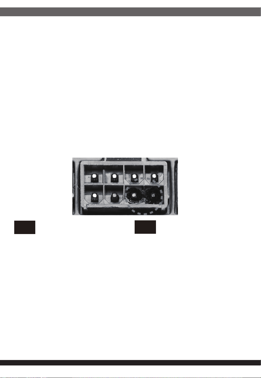
10. POWER SUPPLY CONNECTOR OVERUSE DEFINITION
7. Reliability:
8. Mechanical:
Power supply connector overuse definition
EN
A single PCIe 8pin cable and connector’s maximum current rating is
12.5A, which is 150W (+12V x 12.5A). So SilverStone’s warranty will not
cover damages or malfunction resulting from the use of a graphics card
or expansion card with a single PCIe 8pin connector that exceeds
standard 225W total power draw (150W from PCIe 8pin connector +
75W from PCIe motherboard slot). Similarly, a graphics card or
expansion card with dual PCIe 8pin connectors that exceed 375W total
power draw (300W from two PCIe 8pin connectors + 75W from PCIe
motherboard slot) will also not be covered under warranty.
Peripheral (molex) or SATA connector’s maximum current rating is 5A,
which is 60W (+12V x 5A) or 25W (+5V x 5A). Please ensure connected
devices are operating under these limits. SilverStone’s warranty will not
cover damages or malfunction resulting from usages exceeding these
connectors and their associated cables.
24pin motherboard connector’s maximum current rating for its dual
+12V metal pins are 5A each, which totals 120W (+12V x 5A x 2).
Please ensure +12V drawing devices connected to the motherboard are
operating under these limits. SilverStone’s warranty will not cover
damages or malfunction resulting from usages exceeding these
connectors and their associated cables.
Definition einer Überlastung des
Netzanschlusses
DE
Die maximale Stromstärke eines einzelnen 8-poligen PCIe-Kabels und
Anschlusses beträgt 12,5 A, was 150 W (+12 V x 12,5 A) entspricht.
Daher deckt die SilverStone-Garantie keine Schäden oder
Fehlfunktionen durch den Einsatz einer Grafikkarte oder Erweiterung-
skarte mit einem einzigen 8-poligen PCIe-Anschluss ab, die die
Standardleistungsaufnahme von insgesamt 225 W übersteigt (150 W
vom 8-poligen PCIe-Anschluss + 75 W vom PCIe-Motherboard-Steck-
platz). Ebenso wird die Verwendung einer Grafikkarte oder
Erweiterungskarte mit zwei 8-poligen PCIe-Anschlüssen, die eine
Leistungsaufnahme von insgesamt 375 übersteigen (300 W von den
beiden 8-poligen PCIe-Anschlüssen + 75 W vom PCIe-Mother-
board-Steckplatz) nicht durch die Garantie abgedeckt.
Der maximale Nennstrom von Peripherie- (Molex) oder SATA-An-
schluss beträgt 5 A, was 60 W (+12 V x 5 A) oder 25 W (+5 V x 5 A)
entspricht. Bitte achten Sie darauf, dass verbundene Geräte unter
diesen Grenzwerten arbeiten. Die Garantie von SilverStone deckt keine
Schäden oder Fehlfunktionen aufgrund einer Nutzung ab, die diese
Anschlüsse und ihre zugehörigen Kabel übersteigt.
Der maximale Nennstrom des 24-poligen Motherboard-Anschlusses für
seine dualen +12-V-Metallkontakte beträgt jeweils 5 A, was insgesamt
120 W (+12 V x 5 A x 2) ergibt. Bitte stellen Sie sicher, dass mit dem
Motherboard verbundene +12-V-Geräte unter diesen Grenzwerten
arbeiten. SilverStones Garantie deckt keine Schäden oder
Fehlfunktionen aufgrund einer Nutzung jenseits der Angaben dieser
Anschlüsse und ihrer zugehörigen Kabel ab.
6.4.8 VOLTAGE FLUCTUATIONS – IEC 61000-3-3 (EN 61000-3-3).
6.4.9 HARMONIC CURRENT EMISSION – IEC61000-3-2(EN 61000-3-2).
6.4.10 EN55032:Class B Radio interference (CISPR 32).
6.4.11 ANSI C63.4-2014 / FCC Part 15 Subpart B / ICES-003 lssue 6 Class B
115VAC operation.
The demonstrated MTBF shall be 100,000 hours of continuous operation at 25ƫ
and full load and nominal voltage. The MTBF of the power supply shall be
calculated in accordance with MIL-HDBK-217F. The DC FAN is not included.
8.1 Physical dimension: L180mm*W150mm*H86mm
9. FAN SPEED CONTROL
1. Fan voltage varies with the ambient temperature or output power.
2. Semi-Fanless function @ 40% max load at 25ƫ.
When the internal temperature reaches 60ƫ fan starts.
12
Définition de l'utilisation excessive du
connecteur d'alimentation électrique
FR
Le courant nominal maximum d'un périphérique (Molex) ou d'un
connecteur SATA est de 5 A, ce qui correspond à 60 W (+12 V x 5 A)
ou 25 W (+5 V x 5 A). Veuillez vous assurer que les appareils
connectés fonctionnent dans ces limites. La garantie de SilverStone
ne couvre pas les dommages ou les dysfonctionnements résultant
d'utilisations dépassant ces connecteurs et leurs câbles associés.
Le courant nominal maximal des connecteurs 24 broches de la carte
mère pour ses doubles broches métalliques +12 V est de 5 A chacun,
ce qui représente au total 120 W (+12 V x 5 A x 2). Veuillez vous
assurer que les dispositifs de tension +12 V connectés à la carte mère
fonctionnent dans ces limites. La garantie de SilverStone ne couvre
pas les dommages ou les dysfonctionnements résultant d'utilisations
dépassant la capacité de ces connecteurs et de leurs câbles
associés.
Le courant nominal maximum d'un câble et d'un connecteur PCIe 8
broches unique est de 12,5 A, ce qui correspond à 150 W (+12 V x
12,5 A). La garantie de SilverStone ne couvre donc pas les dommages
ou les dysfonctionnements résultant de l'utilisation d'une carte
graphique ou d'une carte d'extension avec un connecteur PCIe 8
broches unique qui dépasse une consommation énergétique totale de
225 W standard (150 W provenant du connecteur PCIe 8 broches + 75
W provenant de l'emplacement de la carte mère PCIe). De même, une
carte graphique ou une carte d'extension avec deux connecteurs PCIe
8 broches qui dépasse une consommation énergétique totale de 375 W
(300 W provenant des deux connecteurs PCIe 8 broches + 75 W
provenant de l'emplacement de la carte mère PCIe) ne sera également
pas couverte dans le cadre de la garantie.
La corrente massima di un singolo cavo PCIe a 8 pin e del connettore
è 12,5 A, corrispondente a 150 W (+12 V x 12,5 A). Pertanto, la
garanzia di SilverStone non copre danni o malfunzionamenti derivanti
dall'utilizzo di una scheda grafica o una scheda di espansione con un
singolo connettore PCIe a 8 pin che supera l'assorbimento totale di
225 W (150 W da connettore PCIe a 8 pin + 75 W da slot PCIe).
Analogamente, la garanzia non copre anche una scheda grafica o
una scheda di espansione con doppi connettori PCIe a 8 pin che
superano l'assorbimento totale di 375 W (300 W da doppi connettori
PCIe a 8 pin + 75 W dalla scheda madre PCIe).
La corrente massima del connettore periferico (molex) o SATA è 5 A,
corrispondente a 60 W (+12 V x 5 A) o 25 W (+5 V x 5 A). Assicurarsi
che i dispositivi collegati funzionino entro questi limiti. La garanzia di
SilverStone non copre danni o malfunzionamenti derivanti da uso
eccessivo di questi connettori e dei relativi cavi.
La corrente massima del connettore a 24 pin per scheda madre per i
suoi due pin di metallo a +12 V è di 5 A ciascuno, per un totale di 120
W (+12 V x 5 A x 2). Assicurarsi che i dispositivi a +12 V collegati alla
scheda madre funzionino con questi limiti. La garanzia di SilverStone
non copre danni o malfunzionamenti derivanti da uso eccessivo di
questi connettori e dei relativi cavi.
Definizione di uso eccessivo del connettore
di alimentazione
IT
La corriente máxima de un solo cable PCIe de 8 pines es 12,5A, lo
que son 150W (+12V x 12,5A). Por tanto, la garantía de SilverStone
no cubrirá daños o fallos provocados por el uso de una tarjeta gráfica
o de expansión con un único conector PCIe de 8 pines que exceda el
total estándar de 225W (150W del conector PCIe de 8 pines + 75W
del zócalo PCIe de la placa base). De igual modo, una tarjeta gráfica
o de expansión con conectores duales PCIe de 8 pines que superen
375W de potencia (300W de los dos conectores PCIe de 8 pines +
75W del zócalo de la placa base) tampoco será cubierta por la
garantía.
La corriente máxima del conector de periféricos (molex) o SATA es
5A, que son 60W (+12V x 5A) o 25W (+5V x 5A). Por favor,
asegúrese de que los dispositivos conectados funcionan dentro de
estos límites. La garantía de SilverStone no cubrirá daños o fallos a
resultas de un uso excesivo de estos conectores y sus cables
asociados.
La corriente máxima del conector de 24 pines de la placa base para
sus pines de metal duales de +12V es de 5A cada uno, para un total
de 120W (+12V x 5A x 2). Por favor, asegúrese de que los
dispositivos de +12V conectados a la placa base funcionan dentro de
estos límites. La garantía de SilverStone no cubrirá daños o averías a
resultas de un uso excesivo para estos conectores y sus cables
asociados.
Definición de uso excesivo del conector de
la Fuente de alimentación
ES
Определение чрезмерной нагрузки на
коннектор блока питания
RU
Один кабель и коннектор PCIe 8pin поддерживает ток 12.5A, что
равно 150Вт (+12В x 12.5A). Таким образом, гарантийные
обязательства SilverStone не будут действовать если вы
используете видеокарту или другую карту расширения с одним
коннектором PCIe 8pin, которые превышает стандартную общую
потребляемую мощность 225Вт (150Вт через коннектор PCIe 8pin +
75Вт через слот PCIe материнской платы). Аналогично, видеокарта
или другая карта расширения с
двумя коннекторами PCIe 8pin,
которые превышают общую потребляемую мощность 375Вт (300Вт
через коннектор PCIe 8pin + 75Вт через слот PCIe материнской
платы), также не будут покрываться гарантией.
Максимальный номинальный ток периферийного (molex) или SATA
разъёма составляет 5A, что равно 60Вт (+12В x 5A) или 25Вт (+5В x
5A). Пожалуйста, убедитесь, что подключенные устройства
работают в этих пределах. Гарантия SilverStone не будет
распространяться на неисправности,
возникающие в результате
использования этих коннекторов или подключаемых к ним кабелей.
Максимальный номинальный ток 24pin коннектора материнской
платы для его двойных металлических контактов +12В составляет
5A на каждый, что равно 120Вт (+12В x 5A x 2). Пожалуйста,
убедитесь, что устройства, подключенные к линии +12В, работают
в этих пределах. Гарантия SilverStone не будет распространяться
на неисправности, возникающие в
результате использования этих
коннекторов или подключаемых к ним кабелей.
전원 공급 커넥터 과용 정의
KR
埮沂穢ʹͺΖ穆理決挚愕珪嘫瘶汞牢堆洊幞洛冯汆Ͳ嵢昢
洊崫求嵢筞斶穞彺Έ·ΩͲ沋城埪΄ΚΝΧΖΣ΄ΥΠΟΖ汞
懺溣櫖昢垚祢渆Έ汞爣暒捊洊崫ʹͺΖ穆珪嘫瘶汞Έ歆
ʹͺΖ彚汾懺姢枲嵵汞Έ汞穯汊爎刂穞垚埮沂ʹͺΖ穆珪嘫瘶
痗沲勾岞穃獺姢喞筛沫獺姢庂斲殯穞櫲愢旣穞垚暖旇嬖垚
欪沗壟汊懺旇穞滆橐枻城埪決歆廎焲儆滆嵢Έ汞爣暒捊
洊崫ʹͺΖ穆珪嘫瘶儢汞Έ歆ʹͺΖ彚汾懺姢枲嵵汞Έ汞
穯汊爎刂穞垚姆櫂ʹͺΖ穆珪嘫瘶痗沲勾岞穃獺姢喞筛沫獺姢庂
斲殯空壊懺溣櫖昢懺旇空渂滆橐枻城埪
渂懆沫獞ΞΠΝΖΩ嬖垚΄Ͳ΅Ͳ珪嘫瘶汞牢堆洊幞洛冯汆Ͳ嵢昢
洊崫求嵢筞斶穞彺Έ·ΩͲ嬖垚Έ·ΩͲ沋城埪
櫶冶夢沫獞姪汆決峲穢洢穢穞櫖昢廒沗壟柢琢檂穯城埪΄ΚΝΧΖΣ΄ΥΠΟΖ
汞懺溣櫖昢垚決峲穢珪嘫瘶愕決歆櫶冶夞垚理決挚汞洛冯汊
爎刂穞櫲斲殯穮求嵢桮愢旣穞垚暖旇決喞欪沗壟汊懺旇穞滆
橐枻城埪
姆櫂·匎暓穆櫖斲殯夞垚穆彚汾懺姢珪嘫瘶汞洛冯洊幞垚
Ͳ決彶儇儇穯凊儆Έ·ΩͲΩ沋城埪彚汾懺姢櫖
櫶冶夢·沫獞儆空埿穢凊惾廒求嵢沗壟夞壊嵣穞柳柢欪
΄ΚΝΧΖΣ΄ΥΠΟΖ汆決珪嘫瘶喞分崮理決挚汞穢凊庂爎刂空昢
斲殯穮求嵢桮愢旣穞垚暖旇決喞処沫櫖堆空昢懺沫穞滆橐枻城埪
13
電力供給コネクタの使用限度超過に関する説明
JP
単一のPCIe8ピンケーブルおよびコネクタの最大定格電流は12.5Aで
150W(+12Vx12.5A)となります。それで定格225W合計電力消費(PCIe8
ピンコネクタからの150W+PCIeマザーボードスロットからの75 W )を超
える、単一PCIe8ピンコネクタ装備のグラフィックスカードまたは拡張カー
ド使用によって生じた損傷や故障の場合、SilverStoneの製品保証は適用
外となります。同様に、375W合計電力消費(2基のPCIe8ピンコネクタから
の300W+PCIeマザーボードスロットからの75W)を超える、デュアルPCIe
8ピンコネクタ装備のグラフィックスカードまたは拡張カード使用によって
生じた損傷や故障の場合も、製品保証適用外となります。
周辺用(molex)またはSATAコネクタの最大定格電流は5Aで、60W
(+12Vx5A)または25W(+5Vx5A)となります。接続された装置がこれら
限度以内で動作することを確認してください。これらコネクタおよび関連ケ
ーブルの定格を超える使用法で生じた損傷や故障については、
SilverStone製品保証対象外となりますのでご注意ください。
24ピンマザーボードコネクタのデュアル+12V金属製ピンに対する最大定
格電流はそれぞれ5Aなので合計は120W(+12Vx5Ax2)となります。接
続される+12V入力のデバイスが、これら上限以内で動作することをご確
認ください。これらコネクタおよび関連ケーブルでの限界を超えた使用で
生じた損 傷または 故 障は、SilverStoneによる製品保証対象外となります。
ᴵ3&,HSLQ⬉⑤㒓Ϣ༈ⱘ᳔乱ᅮ⬉⌕Ў$ˈ⪺⡍᭄:
˄9[$˅DŽℸˈ䫊ⱘ⬉⑤ֱϡࣙᣀ⫼Ѣᴵ3&,H
SLQ༈Пᰒᠽܙˈ䍙䖛ޚ:ᘏࡳ㗫㣗ೈ᠔䗴៤ⱘᤳണ
ᬙ䱰˄:ⱘ3&,HSLQ༈:ⱘЏᵓ3&,Hᦦῑ˅DŽҹℸ㉏
ˈ㢹ঠ3&,HSLQ༈ⱘᰒᠽܙˈ䋳䕑ϔԚ䍙䖛:ᘏ
ࡳ㗫ˈ㾚ৠϡሲֱ㣗ೈݙ˄:ᴹ㞾ϸϾ3&,HSLQ༈:ⱘ
Џᵓ3&,Hᦦῑ˅DŽ
SLQ˄PROH[˅6$7$༈ⱘ᳔乱ᅮ⬉⌕Ў$ˈ:˄9[
$˅:˄9[$˅DŽ䇋⹂ֱ䖲ⱘ䆒ⱚԢѢℸ䰤ࠊϟ䖤㸠
DŽ
䫊ϡֱ䍙ߎ⬉⑤կᑨ఼༈ঞ݊Ⳍ݇㒓ᴤПՓ⫼䋳䕑Ϟ䰤᠔䗴
៤ⱘᤳണᬙ䱰DŽ
SLQЏᵓ༈ⱘঠ9䞥ሲ䩜㛮᳔乱ᅮ⬉⌕Ў$ˈ:˄
9[$[˅DŽ䇋⹂ֱ䖲ⱘ9䆒ⱚԢѢℸ䰤ࠊϟ䖤㸠DŽ
䫊ϡֱ䍙ߎ⬉⑤կᑨ఼༈ঞ݊Ⳍ݇㒓ᴤПՓ⫼䋳䕑Ϟ䰤᠔䗴
៤ⱘᤳണᬙ䱰DŽ
⬉⑤կᑨ఼༈䖛ᑺՓ⫼ᅮН
CN
䳏⑤կឝ఼丁䘢ᑺՓ⫼ᅮ㕽
TW
ஂṱ3&,HSLQ䳏⑤㎮㟛丁ⱘ᳔両ᅮ䳏⌕⚎$ˈ⪺⡍ᭌ:
˄9[$˅DŽℸˈ䡔ⱘ䳏⑤ֱϡࣙᣀ⫼ᮐஂṱ3&,H
SLQ丁П乃ܙˈ䍙䘢῭⑪:㐑ࡳ㗫㆘ೡ᠔䗴៤ⱘ᧡າ
ᬙ䱰˄:ⱘ3&,HSLQ丁:ⱘЏ″ᵓ3&,Hᦦῑ˅DŽҹℸ
串ˈ㢹٭䲭3&,HSLQ丁ⱘ乃ܙˈ䉴䓝ϔԚ䍙䘢:
㐑ࡳ㗫ˈ㽪ৠϡቀֱ㆘ೡܻ˄:՚㞾ܽן3&,HSLQ丁:
ⱘЏ″ᵓ3&,Hᦦῑ˅DŽ
SLQ˄PROH[˅6$7$丁ⱘ᳔両ᅮ䳏⌕⚎$ˈ:˄9[
$˅:˄9[$˅DŽ䂟⺎ֱ䗷ⱘ䀁٭ⱚԢᮐℸ䰤ࠊϟ䘟㸠
DŽ
䡔ϡֱ䍙ߎ䳏⑤կឝ఼丁ঞ݊Ⳍ䮰㎮ᴤПՓ⫼䉴䓝Ϟ䰤᠔䗴
៤ⱘ᧡າᬙ䱰DŽ
SLQЏ″ᵓ丁ⱘ䲭9䞥ቀ䞱㝇᳔両ᅮ䳏⌕⚎$ˈ:˄
9[$[˅DŽ䂟⺎ֱ䗷ⱘ9䀁٭ⱚԢᮐℸ䰤ࠊϟ䘟㸠DŽ
䡔ϡֱ䍙ߎ䳏⑤կឝ఼丁ঞ݊Ⳍ䮰㎮ᴤПՓ⫼䉴䓝Ϟ䰤᠔䗴
៤ⱘ᧡າᬙ䱰DŽ
ขีดจำกัดการรองรับการใช้งานของขั้วต่อจากพาวเวอร์ซัพพลาย
TH
สำหรับขั้วเชื่อมต่อและสายไฟเลี้ยง PCIe 8 พินสามารถรองรับกระแสได้สูงสุด 12.5
แอมป์หรือหมายถึง 150 วัตต์
(+12V x 12.5A) ดังนั้นการรับประกันจากทาง SilverStone จะไม่ครอบคลุมถึงความ
เสียหายหรือความผิดปรกติซึ่งเกิดขึ้นกับกราฟิกการ์ดรวมถึงการ์ดขยายความยาวที่ใช้งาน
ขั้วเชื่อมต่อ PCIe 8 พิน ซึ่งมันมีการใช้พลังงานรวมทั้งสิ้นเกินกว่ามาตรฐานที่กำหนดคือ
225 วัตต์ (150 วัตต์ จาก PCIe 8 พิน + 75 วัตต์ จากสล๊อต PCIe บน
เมนบอร์ด) อันรวมถึงกราฟิการ์ดหรือการ์ดขยายความยาวที่ใช้ขั้วต่อไฟเลี้ยง PCIe 8
พินจำนวน 2 ชุดซึ่งมีการใช้พลังงานทั้งสิ้น 375 วัตต์ (300 วัตต์ จากขั้ว PCIe 8
พิน 2 ชุด + 75 วัตต์ จากสล๊อต PCIe บนเมนบอร์ด) ซึ่งไม่ครอบคลุมเช่นกัน
ภายใต้การรับประกัน ขั้วเชื่อมต่อ Peripheral หรือ Molex 4 พินและ SATA มันสามารถ
รองรับกระแสได้สูงสุด 5 แอมป์หรือหมายถึง 60 วัตต์ (+12V x 5A) หรือ (+5V
+ 5A) กรุณาให้แน่ใจว่าอุปกรณ์ที่ใช้งานมีการใช้พลังงานไม่เกินกว่าขีดจำกัดที
่รองรับ ดัง
นั้นการรับประกันจากทาง SilverStone จะไม่ครอบคลุมถึงความเสียหายหรือความผิด
ปรกติจากอุปกรณ์ที่เชื่อมต่อใช้งานจากตัวสายเชื่อมต่อซึ่งมีการใช้พลังงานเกินกว่าขีด
จำกัด
กระแสไฟฟ้าสูงสุดของขั้วต่อเมนบอร์ด 24 พิน สำหรับพินโลหะ +12V คู่แต่ละอันมีค่า
5A ซึ่งรวมทั้งหมดเป็น 120W
(+12V x 5A x 2) โปรดตรวจสอบให้มั่นใจว่าอุปกรณ์ตัวดึงพลังงาน +12V ที่เชื่อม
ต่อกับเมนบอร์ดสามารถทำงานภายใต้ขีดจำกัดเหล่านี้ได้ การรับประกันของ SilverStone
ไม่คุ้มครองความเสียหาย หรื
ออาการเสียที่เป็นผลจากการใช้เกินขีดจำกัดของขั้วต่อและสาย
เคเบิลที่ใช้เชื่อมต่อเหล่านี้
14
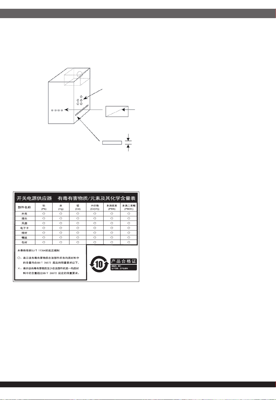
⚎њֱ䅋Փ⫼㗙ঞ䰆☿ⱘⳂⱘˈᅝ㺱ℸѸᓣ䳏⑤կឝ఼ᰖˈᖙ䷜ᅝ㺱ᮐヺড়ϟ߫䷙㽕∖ⱘ←Ёˈ
ϺϨᅝ㺱ཹᕠˈᠡৃϞ䳏⑤DŽ
←ᴤ䊾䷜⚎䰆☿←DŽᴤ䋼乏Ў䰆☿DŽ
←ⱘϞᮍঞو䙞П೧ᔶ䭟ᄨˈ᳔ܻᕥϡৃᮐPPDŽ
←ⱘϞᮍঞو䙞П䭋ṱൟ䭟ᄨˈᇡ㾦㎮䎱䲶ϡৃᮐPP˗㢹ᇀᑺᇣᮐPPˈࠛ䭋ᑺϡফ䰤ࠊDŽ
←ᑩ䚼ϡৃ᳝䭟ᄨDŽᑩ䚼ϡৃ᳝ᓔᄨDŽ
ⳈᕥϡᮐPP
ᇡ㾦㎮ϡᮐPP
ᇀᑺᇣᮐPPࠛ䭋ᑺϡ䰤
Openings that do not exceed 1mm in width regardless of length
Openings that do not exceed 5mm in any dimension
ᴀ⫶ક䔌ߎ᳝䱾㛑䞣ˈ⚎䙓ܡ᪡ᰖⱐ⫳䱾ˈ䷜ᮐ㺱ܹ㋏㍅″←Ϻᇛ᠔᳝䀁٭ᅝ㺱ཹ⭊ᕠᠡৃ䭟ଳ䳏⑤DŽ
ᴀ⫶કП䳏⑤䔌ߎ䴲ቀ䳏䰤ࠊൟ䳏⑤ˈ䂟䗷Փ⫼䰆☿←П䙞ˈҹ䙓ܡ☿♑䱾ⱐ⫳DŽ
%60,52+6䊛㿞
KWWSZZZVLOYHUVWRQHWHNFRPGRZQORDGV36856'SGI
This device complies with Part 15 of the
FCC Rules.Operation is subject to the
following two conditions:
(1) this device may not cause harmful
interference, and
(2) this device must accept any
interference received, including
interference that may cause
undesired operation.
Please refer to SilverStone website for latest specifications updates.
the power supply is only suitable for Information
Technology & Audio/Video equipment.
※付属の電源コードは当該製品専用です。他の機器に使用しないでください。
・本製品は2050Wの出力が可能な高出力電源となります。
・100V環境の場合、2050Wの出力を行う事はできません、20Aを許容する環境にてご利用ください。
・一般家庭のコンセント(1500W)の場合は、1300W未満の消費電力でご利用ください。
・日本国内向けに販売されている本製品の付属電源ケーブルは100V(最大15A)専用となります。
・本製品に200V用電源ケーブル、および100V/20A用電源ケーブルの同梱はございません。
・100V/15A以外の環境でご利用の際は、安全の為、必要な電源ケーブルを別途ご用意ください。
Model (safety certification) : SST-AX2050MCPT-C
NO. G11248380