1
INSTRUCTION MANUAL
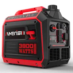
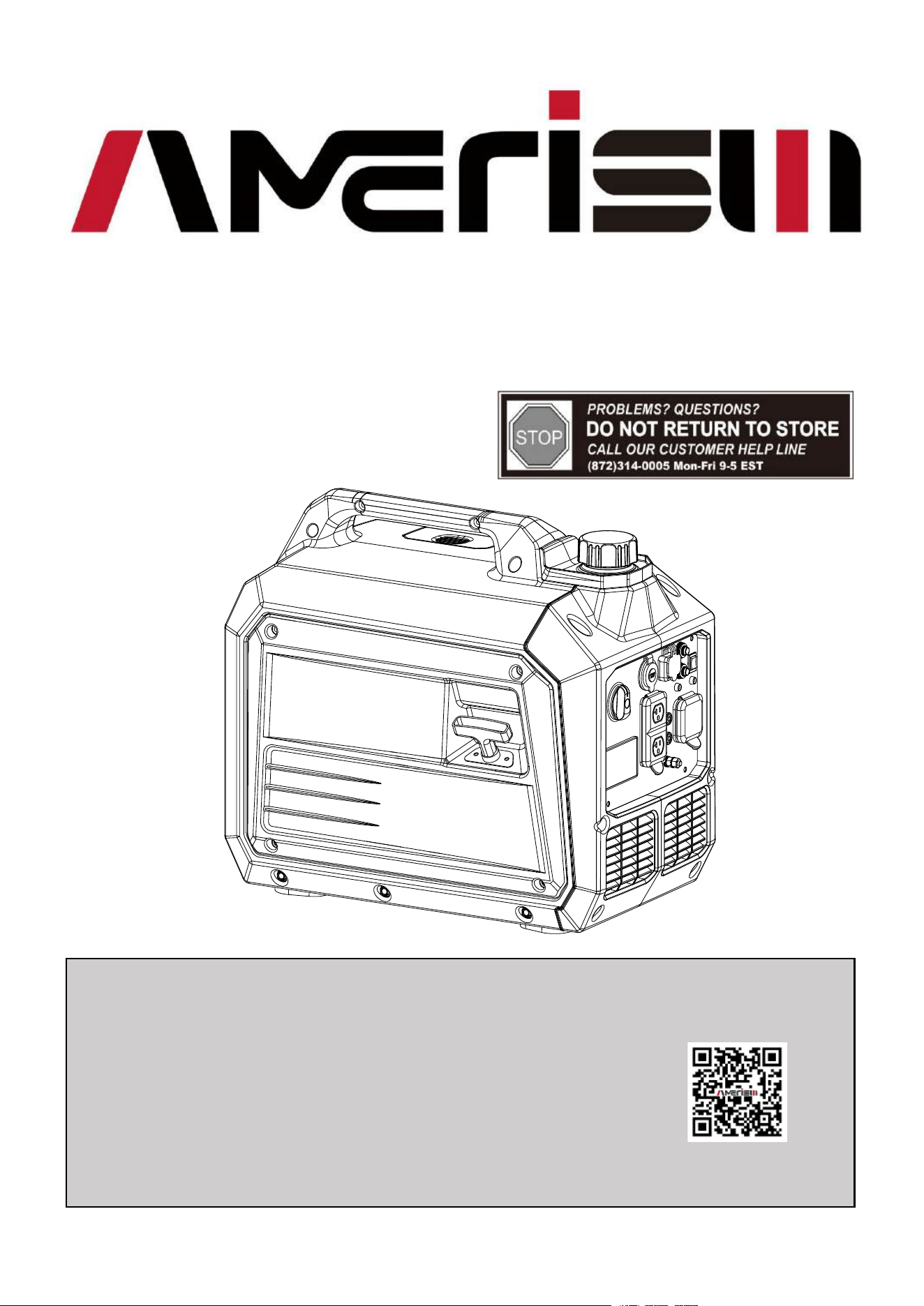
3800W Inverter Generator
Model # AL5035C
Have product questions or need technical support? Please scan the QR code
to enter our official website and contact us!
Website:
Toll free: 1-872-314-0005 Mon-Fri 9-5 EST
Website
Email:
support@amerisuninc.com
https://amerisuntools.com

2

3
CONTENTS
TECHNICAL DATA......................................................................................................................................................... 3
INTRODUCTION
............................................................................................................................................................. 4
SAFETYINFORMATION
..............................................
..................................................................................................4
GENERAL SAFETY RULES ............................................................................................................................................5
SYMBOLS.......................................................................................................................................
................................. 7
KNOWING YOUR INVERTER GENERATOR .............................................................................................................. 8
GENERATOR PREPARATION.....................................................................................................................................12
GENERATOR OPERATION ......................................................
................................................................................... 16
MAINTENANCE ............................................................................................................................................................ 19
TROUBLESHOOTING...................................................................................................................................
............... 23
EXPLODED VIEW & PARTS LIST
..............................................................................................................................25
WARRANTY
.................................................................................................................................................................. 29
TECHNICAL DATA
3800W Inverter Generator Model#AL5035C
Engine type: 4 stroke, OHV, single cylinder with forced
air-cooling system
Start type: Manual
Phase: Single
Rated wattage: 3300 W
Surge wattage: 3800 W
Rated voltage: 120 V
Rated current: 27.5 A
Rated frequency: 60 Hz
Displacement: 149 cc
Run time at 50% load: 4.75 hour
Spark plug gap: 0.024-0.028 inch
Fuel tank capacity: 1.3 Gallon
Engine Oil capacity: 16.2Fl.oz
USB output voltage: 5V
Noise rating: 70dB at 23 feet
Package dimensions(L x W x H): 21.9x13.4x19.5 inch
Net Weight: 50.7 lbs

4
INTRODUCTION
Thank You for Purchasing an AMERISUN Product. This manual provides information regarding the safe
operation and maintenance of this product. Every effort has been made to ensure the accuracy of the
information in this manual. AMERISUN reserves the right to change this product and specifications at any
time without prior notice.
Please keep this manual available to all users during the entire life of the generator. This manual contains
special messages to bring attention to potential safety concerns, generator damage as well as helpful
operating and servicing information. Please read all the information carefully to avoid injury and machine
damage.
QUESTIONS? PROBLEMS?
Please contact our Customer Service Dept. with any questions and/or comments, either by Email:
solve any issues that you might encounter.
NOTICE REGARDING EMISSIONS
Engines that are certified to comply with U.S. EPA emission regulations for SORE (Small Off Road
Equipment), are certified to operate on regular unleaded gasoline, and may include the following emission
control systems: (EM) Engine Modifications and (TWC) Three-Way Catalyst (if so equipped).
SAFETY INFORMATION
Before operating this generator, read and observe all warnings, cautions, and instructions on the generator
and in this Owner’s Manual.
NOTE: The following safety information is not meant to cover all possible conditions and situations that
may occur. Read the entire Owner’s Manual for safety and operating instructions. Failure to follow
instructions and safety information could result in serious injury or death.
This safety alert symbol is used to identify safety information about hazards that can result in personal
injury.
A signal word (DANGER, WARNING, or CAUTION) is used with the alert symbol to indicate
the likelihood and the potential severity of injury. In addition, a hazard symbol may be used to
represent the type of hazard.
DANGER Indicates a hazard, which, if not avoided, will result in death or serious injury.
WARNING Indicates a hazard, which, if not avoided, could result in death or serious injury.
CAUTION Indicates a hazard, which, if not avoided, might result in minor or moderate injury.
CAUTION when used without the alert symbol, indicates a situation that could result in damage to the
engine or generator.
5
GENERAL SAFETY RULES
DANGER: CARBON MONOXIDE
Using a generator indoors CAN KILL YOU IN MINUTES. Generator exhaust contains carbon monoxide
(CO). This is a poison gas you cannot see or smell. If you can smell the generator exhaust, you are
breathing CO. But even if you cannot smell the exhaust, you could be breathing CO.
NEVER use a generator inside homes, garages, crawlspaces, or other partly enclosed areas. Deadly levels of
carbon monoxide can build up in these areas. Using a fan or opening windows and doors does NOT supply
enough fresh air. ONLY use a generator outside and far away from windows, doors, and vents. These
openings can pull in generator exhaust.
Even if you use a generator correctly, CO may leak into the home. ALWAYS use a battery-powered or
battery-backup CO alarm in the home. If you start to feel sick, dizzy, or weak after the generator has been
running, move to fresh air RIGHT AWAY. See a doctor. You may have carbon monoxide poisoning.
WARNING: The exhaust from this product contains chemicals known to the State of California
to cause cancer, birth defects, or other reproductive harm.
WARNING: This generator may emit highly flammable and explosive gasoline vapors, which
can cause severe burns or even death if ignited. A nearby open flame can lead to
explosion even if it isn’t directly in contact with gasoline.
● Do not operate near open flame.
● Do not smoke near generator.
● Always operate on a firm, level surface.
● Always turn generator off before refueling. Allow generator to cool for at least 2 minutes before
removing fuel cap. Loosen cap slowly to relieve pressure in tank.
● Do not overfill fuel tank. Gasoline may expand during operation. Do not fill to the top of the tank.
● Allow for expansion.
● Always check for spilled fuel before operating.
● Empty fuel tank before storing or transporting the generator.
WARNING: This generator produces powerful voltage, which can result in electrocution.
● ALWAYS ground the generator before using it (see the “Generating set ground” portion of the
“GENERATOR PREPARATION” section).
● Generator should only be plugged into electrical devices, either directly or with an extension cord.
● NEVER connect to a building electrical system without a qualified electrician. Such connections must
comply with local electrical laws and codes. Failure to comply can create a back-feed, which may result
in serious injury or death to utility workers.
● Use a ground fault circuit interrupter (GFCI) in highly conductive areas such as metal decking or
steel work. GFCIs are available in-line with some extension cords.
● Do not use in rainy conditions.
● Do not touch bare wires or receptacles (outlets).
● Do not allow children or non-qualified persons to operate.
WARNING: This generator produces heat when running. Temperatures near exhaust can exceed
150℉ (65℃).
● Do not touch hot surfaces. Pay attention to warning labels on the generator identifying hot parts of the
machine.

6
● Allow generator to cool down after use before touching engine or areas of the generator that become
hot during use.
CAUTION: Misuse of this generator can damage it or shorten its life.
● Only use generator for its intended purposes.
● Operate only on dry, level surfaces.
● Allow generator to run for several minutes before connecting electrical devices.
● Shut off and disconnect any malfunctioning devices from generator.
● Do not exceed the wattage capacity of the generator by plugging in more electrical devices than the unit
can handle.
● Do not turn on electrical devices until after they are connected to the generator. Turn off all connected
electrical devices before stopping the generator.
● Turn the engine switch to “OFF” position when the engine is not running.
IMPORTANT SAFETY INSTRUCTIONS
● Ensure that adequate ventilation is provided while the generator is in operation.
● The muffler is hot when the generator is running and just stopping. Be careful not to touch it.
● Under certain conditions, gasoline is extremely flammable and explosive.
● Be sure to add gasoline in a well-ventilated place. Turn off the engine and let it cool before filling.
● When refueling, keep away from the open fire.
● If there is oil spill while refueling, wipe the spilled gasoline immediately.
● Explosion and Fire. Do not overfill fuel tank. Fill to 1/2 inch from top of tank to allow for fuel
expansion. Overfilling may cause fuel to spill onto engine causing fire or explosion, which will result in
death or serious injury!
● Using should be prohibited in places with high fire risk.
● Do not connect the generator to the power system, or it may cause people to die from electric shock
when they come into contact with the wire; damage the generator or damage the home appliance.
● A pre-operation check must be performed before starting the engine to avoid accidents or equipment
damage.
● Generators must operate at least one meter away from the building and other equipment.
● Please put the generator on the horizontal ground. If the generator is tilted, it may cause gasoline
overflow.
● Be sure to master how to quickly shut off generators and understand the operation of all control
components.
● Children and pets must stay away from the operating area. While the engine is running, all personnel
must be away from its rotating parts.
● If the operation is not proper, there is a potential danger to the generator. Do not operate the generator
with a wet hand.
● Do not operate in the rain, snow, lest wet generator.
● Maintenance of generators to be operated by professionals.
● Generators vibrate in normal use. During and after the use of the generator, inspect both the generator as
well as extension and power supply cords for damage resulting from vibration. Have damaged items
repaired or replaced as necessary. Do not use plugs or cords that show signs of damage such as broken or
cracked insulation.
For power outages, permanently installed stationary generators are better suited for providing backup power
to the home. Even a properly connected portable generator can become overloaded. This may result in
overheating or stressing of the components, possibly leading to a generator failure.
7
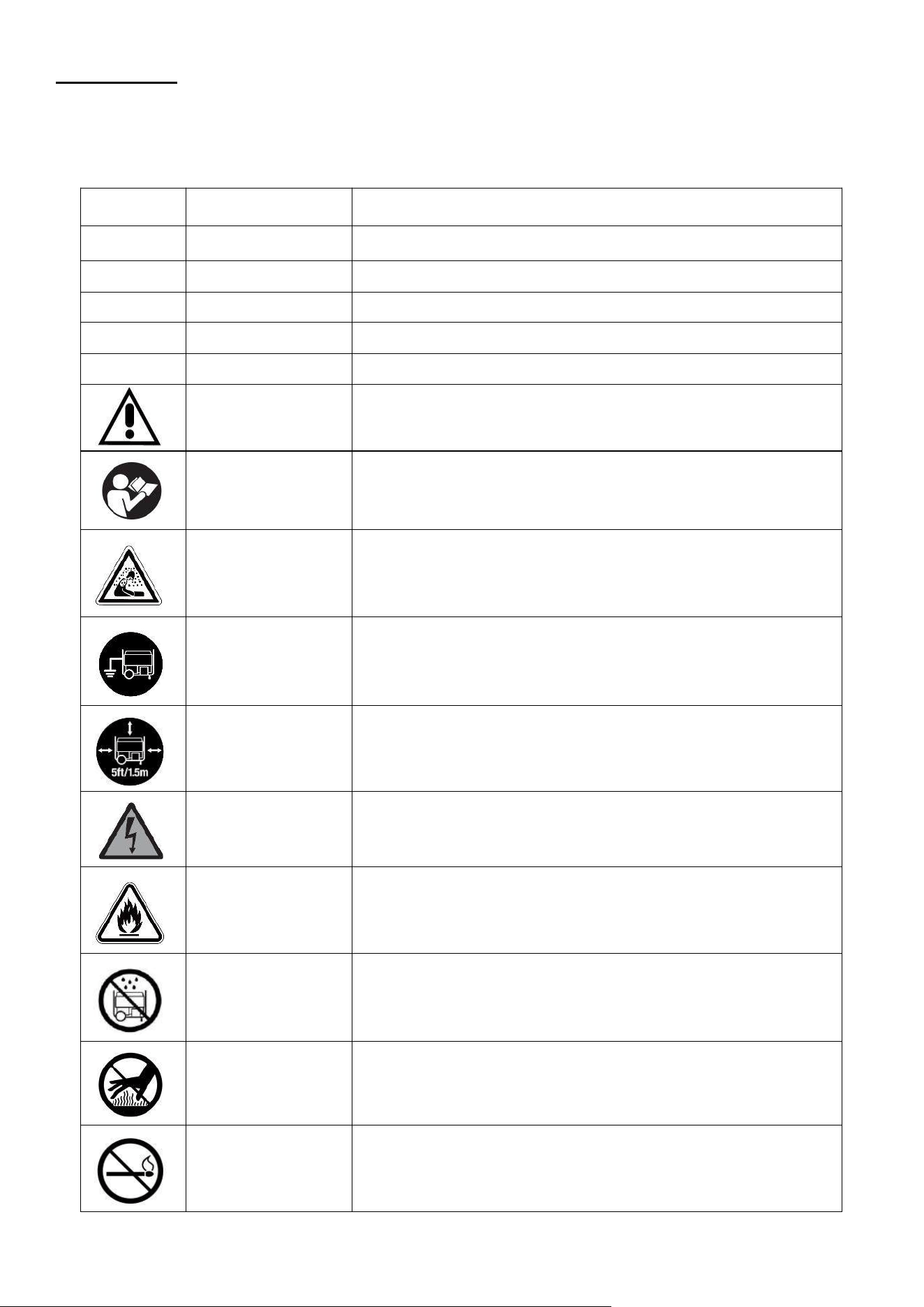
SYMBOLS
Some of the following symbols may be used on this product. Please study them and learn their meaning.
Proper interpretation of these symbols will allow you to operate the product better and safer.
SYMBOL
NAME
DESIGNATION/EXPLANATION
V
Volts
Voltage
A
Amperes
Current
Hz
Hertz
Frequency (cycles per second)
W
Watts
Power
MIN
Minutes
Time
Safety Alert
Precautions that involve your safety.
Read the user’s
manual
To reduce the risk of injury, user must read and understand
user’s manual before using this product.
Carbon monoxide
hazard
Never operate the generator in an enclosed area. Engine
exhause contains carbon monoxide. Only operate the
generator outside and away from windows, doors and vents.
Ground
Consult with local electrician to determine grounding
requirements before operation.
Clearance
Keep all objects at least 5 feet (1.5m) from generator. Heat
from the muffler and exhaust gas can ignite combustible
objects.
Electric shock
alert
Beware of electric shock hazard.
Fire/Explosion
Fuel and its vapors are extremely flammable and explosive.
Fire or explosion can cause severe burns or death. Keep
generator at least 5 feet (1.5m) from all objects to prevent
combustion.
Wet conditions
alert
Do not expose to rain or use in damp locations.
Hot Surface
To reduce the risk of injury or damage, avoid contact with any
hot surface.
Open Flame Alert
Fuel and its vapors are extremely flammable and explosive.
Keep fuel away from smoking, open flames, sparks, pilot
lights, heat, and other ignition sources.
8
1 2
12
3 4 5
8
6
7
9 10 11 13 14
16
17
15
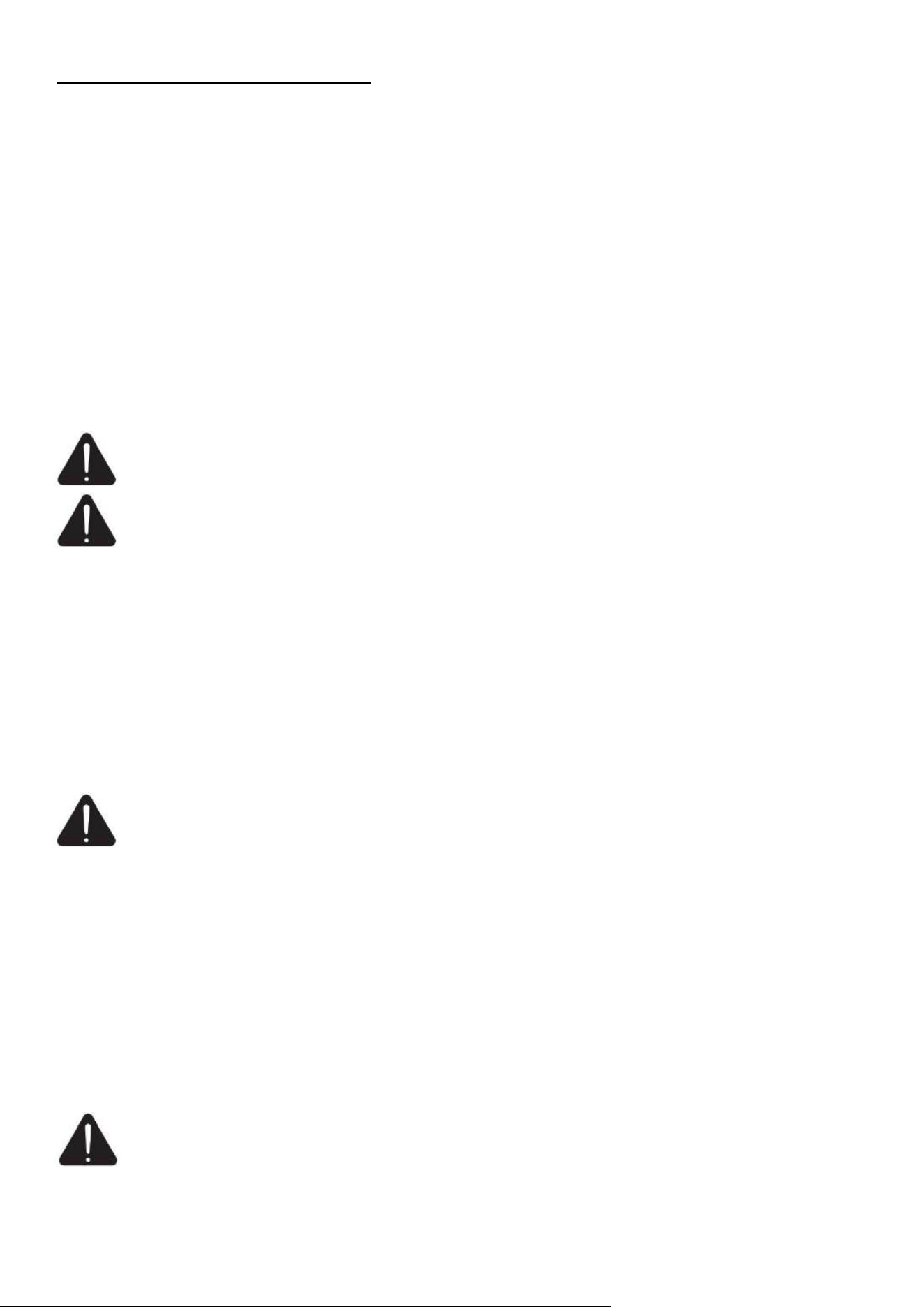
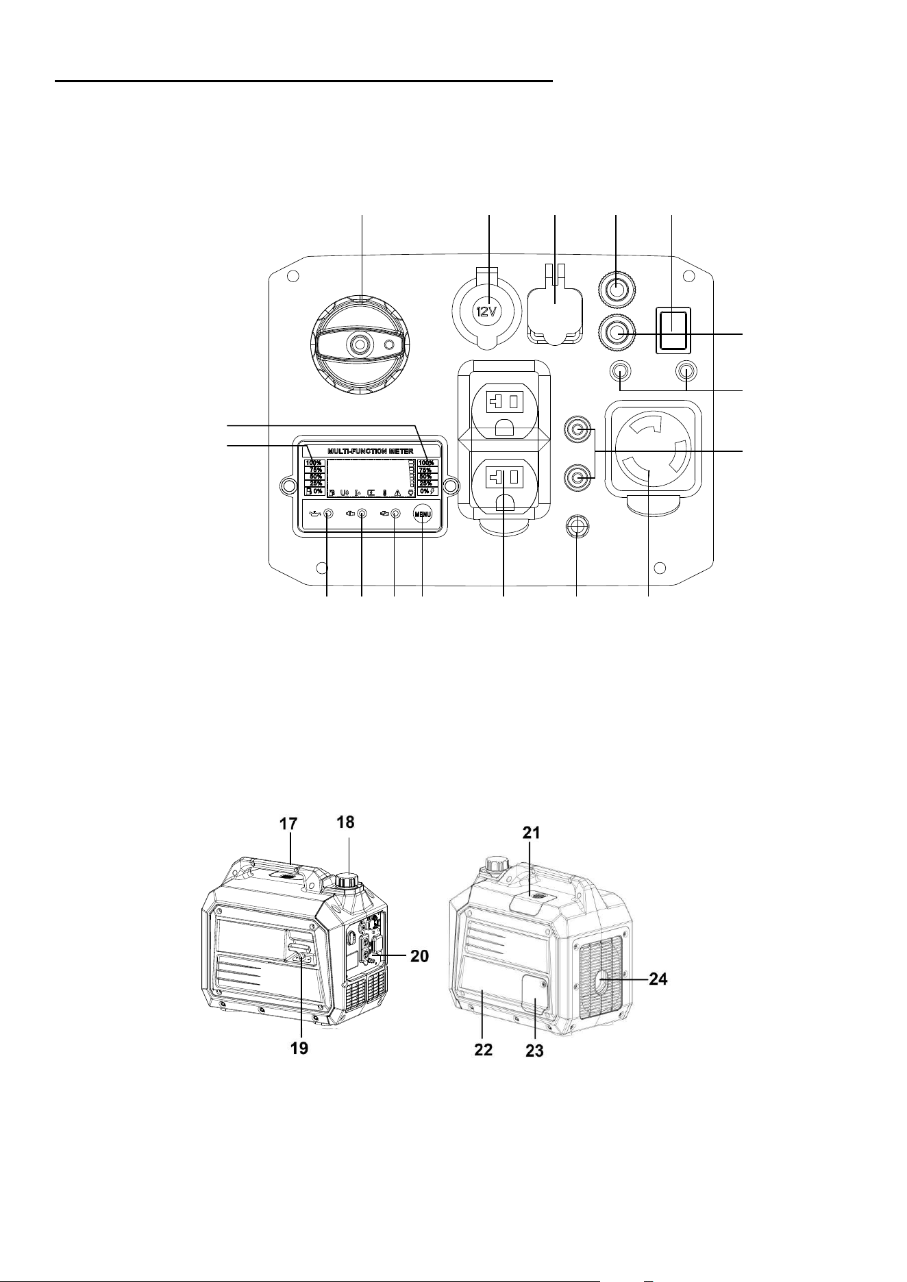
KNOWING YOUR INVERTER GENERATOR
Use the illustrations below to become familiar with the locations and functions of the various components and
controls of this generator.
Control Panel
1
Engine Switch
7
Fuel Level Indicator
13
Ground(Earth)Terminal
2
12V DC Port
8
Oil Warning Light
14
120V 30A AC Outlet
3
USB Port
9
Overload Indicator
15
120V 20A AC Breaker
4
DC Breaker
10
Running Indicator
16
Parallel Outlets
5
ECO Switch
11
Menu Button(AC Reset)
6
Load Indicator
12
120V 20A AC Outlets
17
Carrying Handle
21
Spark Plug Maintenance Cover
18
Fuel Tank Cap
22
Air Filter Maintenance Cover
19
Recoil Start Handle
23
Oil Maintenance Cover
20
Control Panel
24
Muffler Exhaust Exit
17
CO Indicator
9
Connection Plugs(AC socket)
The Volt outlet is overload protected by the inverter. Each socket will power 120Volt AC, single phase,
electrical loads requiring up to 3.3 kW.
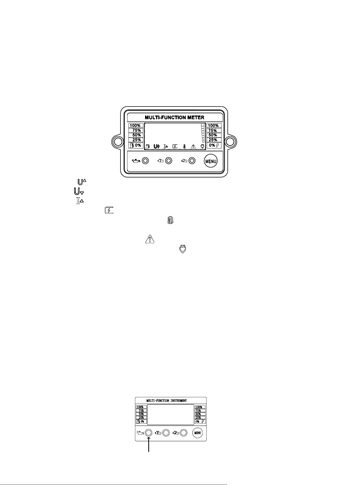
Multi-function Meter
The multi-function meter can be used for displaying fuel level, load percent, output wattage, voltage, run
time and total run time as applicable.
MENU bu tton
We can check information by pressing the MENU button once on the display.
When the generator is in some output exception co
ndition, press the MENU button for 3 seconds to restore
the display.
Load Indicator
The load indicator on the right side of the meter shows the loaded electric devices load percent.
Fuel Level Indicator
The indicator on the left side of the meter is designed to remind the fuel level in current time. Remind us to
add the fuel in time.
Oil Warning L ight (Yellow)
The low oil level alarm system is designed to prevent engine damage due to insufficient oil in the crankcase.
The low oil le
vel alarm system automatically shuts down the engine before the engine oil in the crankshaft
box is lowered to safety (the generator engine switch remains “ON”).
When over-voltage, will flashing
;
When low-voltage,
will flashing;
When over-current, will flashing;
When short-circuit happened, flashing, remove all applied loads
;
If the IGBT temperature is in a high level, the signal will flashing
;
In all above condition s , press the MENU button for about 3 seconds, the information will be restored.
If the generator needs maintenance, the light
will flashing, maintenance your generator in time.
When the generator is in normal operation, the indicator
lights up constantly.
10
NOTE: After the low oil level alarm system shuts down the engine, if you start the engine again, the low
oil alarm indicator (yellow) lights up and the engine cannot run. If this happens, please fill in the oil and
then restart the generator.
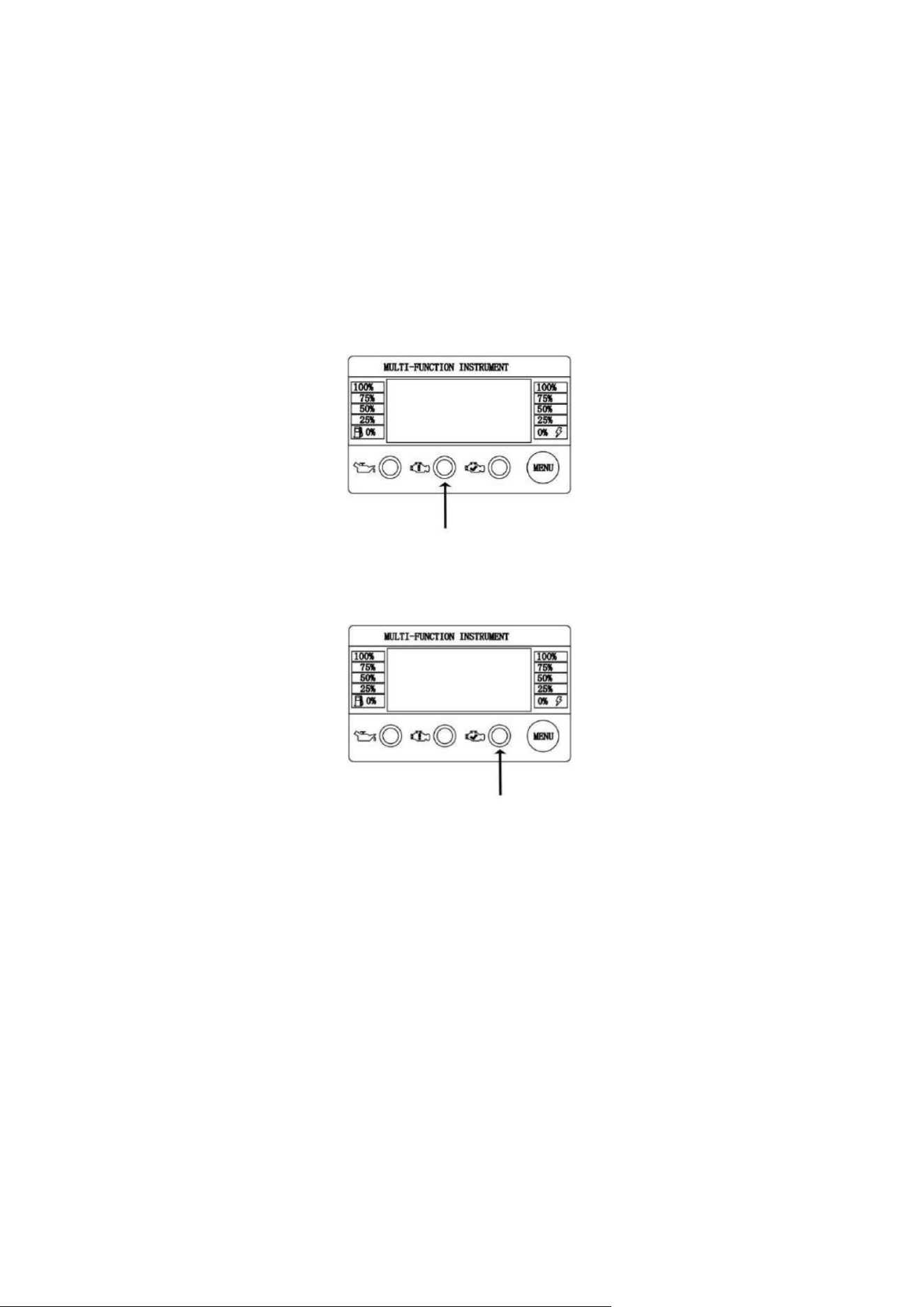
Overload Indicator (Red)
During engine starting, it is normal for the overload indicator(Red) to illuminate for a few seconds.
If overload indicator(Red) stays illuminated and the running indicator(Green) turns off, the engine will
continue to run without output power. In this condition, remove all applied loads and determine if attached
devices exceed recommended output power. Check for faulty or shorted connections. To restore electrical
output, press the MENU button about 3 seconds to reset.
Start engine. If condition was corrected, the overload indicator (Red) will not illuminate and electrical output
will be restored. Loads can be applied once the running indicator (Green) illuminates.
After above operating, if the Overload Indicator (Orange) returns, contact our customer service.
Running Indicator (Green)
The output indicator lights up when generating set starts and has normal output.
CO Alarm Light(Red)
When the concentration of CO exceeds the standard, the CO alarm light will turn on Red and the generator
stops soon.
CO Failure Light(Yellow)
When the CO sensor is broken, the CO failure light will be on Yellow.
DC Breaker Button
The DC breaker button is used to protect the 12V 8A DC output receptacle. When this outlet receptacle are
overloaded, the breaker will pop out. In this condition, reduce the loads and then press the DC breaker
button.
AC Breaker Button
The AC breaker button is used to protect the 120V 20A AC output receptacle. When these outlet receptacle

11
are overloaded, the breaker will pop out. In this condition, reduce the loads and then press the AC breaker
button.
Grounding Terminal
The grounding terminal is designed to prevent electric shock by connecting it to the grounding wire. The
generating set must be properly grounded before operation.
The generator is equipped with an equipment ground connecting the generator frame and
the ground terminals on the AC output receptacles. This allows the generator to be used as a portable
without grounding the frame of the generator.
The generator (stator winding) is isolated from the frame and from the AC receptacle ground pin. Electrical
devices that require a grounded receptacle pin connection will not function if the receptacle ground pin is
not functional.
ECO Switch
When the energy-saving switch is in the energy-saving position, the generator is in the energy-saving state.
When disconnecting or using low power, the engine automatically returns to a low speed state, thus
reducing engine fuel consumption
Full Speed
“full speed” means that the energy-saving state(ECO switch) is in OFF position and the engine is always at
high speed, which is suitable for the situation where the load of electrical appliances varies greatly.
When the energy-saving switch is in full-speed position, the engine will remain in a high speed state.
● In order to reduce the change of voltage, the energy saving switch should be in the position of "full
speed" when the electrical equipment needs a large instantaneous power, or when the generator is
connected with the load of the high power apparatus at the same time.
● When using 12 V DC output, put the energy-saving switch in full-speed position.
WARNING: In the non-overload state, the output can not be restored by pressing the reset key.
Each time the engine is started, the number of effective operation times of the protection cut-off
switch is 5 times, or the engine needs to be restarted.
Parallel Operation
Make sure that the generating set is in a good running state before connecting it to other generating sets.
The total power of electric devices should not exceed rated power of generating set.
When electric motor starts, the overload indicator will light up and normally it will stop within 4 seconds. If
customer service.
During parallel operation, energy-saving switches of generating sets should be in the same position. To
parallel operation, perform the following steps:
1. Connect one generating set to other generating set(s) in parallel. Use the parallel kit to make the parallel
connection (the parallel kit needs to be purchased separately).
2. Start the engine in proper order and make sure that the running indicator (green) is normal.
3. Connect the plug of electric devices to the AC receptacle of parallel kit.
4. Run the electric devices.
NOTE: We advise two parallel generators are same model, or it may cause a low voltage output, which
could damage appliances powered by the generators.

12
GENERATOR PREPARATION
The following section describes steps necessary to prepare the generator for use. If after reading this section,
you are unsure about how to perform any of the steps please call (872) 314-0005 Mon-Fri 9-5 EST for
customer service. Failure to perform these steps properly can damage the generator or shorten its lifespan.
Unpacking
Unpack the generator and all its parts. Do not discard the carton or any packaging until the generator is
completely assembled.
Operating Location
● Only use OUTSIDE and place the generating set in a well-ventilated area.
● Only operate the generating set on a flat, level surface and in a clean, dry operating environment.
● Allow two feet clearance on all side of the generating set while operating it outdoors.
● Operate in specified area, if any problem on applicable occasion, please consult the authorized local
dealers. In some areas, generating set must be registered with the local utility. Generating set used to
construction sites may be subject to additional rules and regulations.
DANGER: The exhaust of the generating set contains carbon monoxide, using engine indoors
CAN KILL YOU! NEVER use inside any building or any kind of enclosure, EVEN IF doors and
windows are open. Place the generating set in a well-ventilated and clean area. Note the wind direction and
air current when place the generating set.
High Altitude
This generating set may require a high altitude carburetor kit to ensure correct operation at high altitudes.
Consult the authorized local dealer for high altitude kit information if you always operate your engine at
altitudes above 5,000 feet (1,500 meters).
CAUTION: Even with carburetor modification, generating set horsepower will decrease about
3.5% for each 1,000 feet (300 meters) increase in altitude. The effect of altitude on
horsepower will be greater than this if no carburetor modification is made.
Operation the engine at altitude below 5,000 feet (1,500 meters) with modified carburetor may cause the
generating set to overheat and result in serious engine damage. Please restore factory specifications of the
carburetor at the dealer when using the engine in a low altitude area.
Operating Condition
Check for loose or damaged parts, signs of oil or fuel leaks, and any other condition that may affect proper
operation. Repair or replace all damaged or defective parts immediately.
Clean the dirt or foreign objects on the surface around exhaust and air intake of generator. DO NOT move or
tip the generating set during operation. Use generating set only for intended uses. If you have questions about
intended use, ask your local dealer.
Engine oil check
WARNING: This engine is not filed with oil before send out to the factory. User must add the
proper amount of oil before operating the generator for the first time. Any attempt to crank or start
the engine before it has been properly filled with the recommended type and amount of oil may result in
13
engine damage and void your warranty.
Engine Oil Recommendations
Only use 4-stroke engine oil of SJ,SL or equivalent level which are in accordance with or higher than API
standard.
Check the API label on oil bottle or other container, and make sure the “SJ,SL” or equivalent level letter is
in the label.
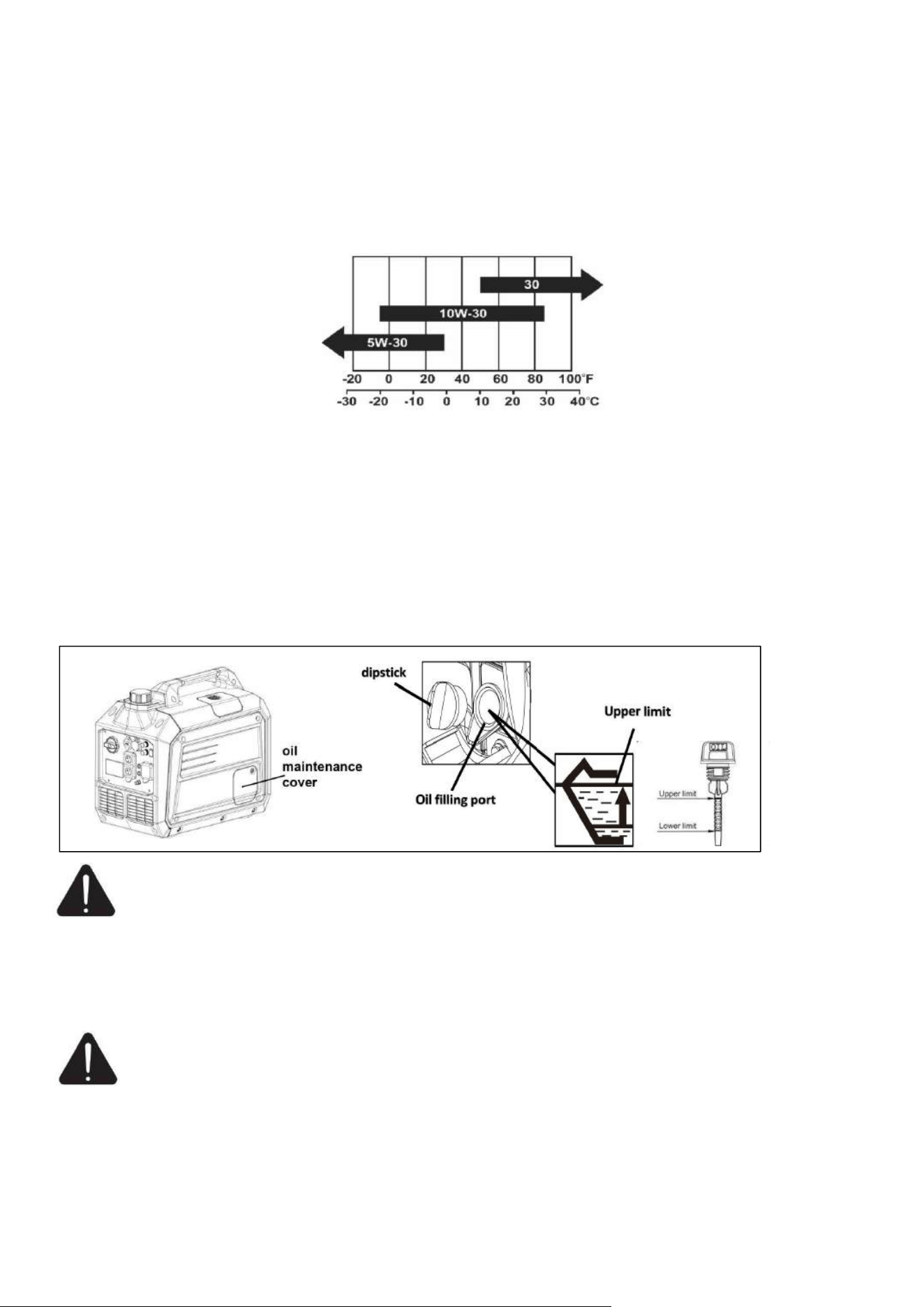
SAE 10W-30 is recommended for general, all-temperature use. Other viscosities shown in the chart may be
used when the average temperature in your area is within the indicated range.
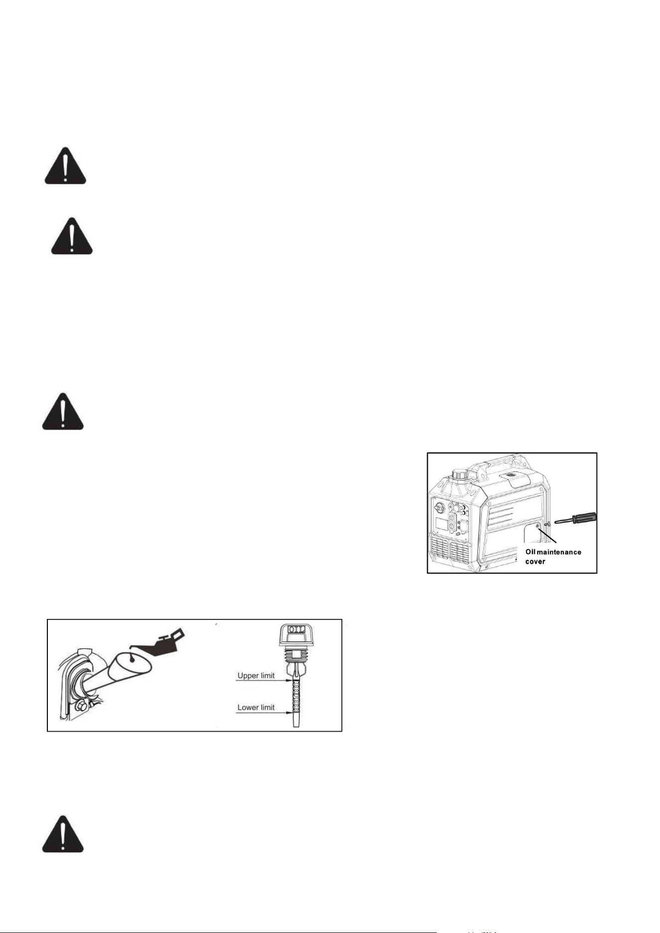
Add the engine oil
1. Remove the oil maintenance cover.
2. Unscrew and remove the dipstick.
3. Add recommended oil to the upper limit(H).
4. Fully tighten the dipstick.
5. Install the cover back to the generator.
NOTE: The oil capacity (rated) of the engine crankcase is 16.2 fl. oz.
Properly dispose of any used oil at an approved waste management facility.
CAUTION: Operate generator only on a level surfaces. Running the engine when the oil level
is low can seriously damage the engine.
The engine is equipped with a low oil sensor (applicable types) that will automatic stop the engine when
the oil level falls below the safe limit. To avoid the inconvenient of an unexpected shutdown, fill to
the upper limit and check the oil level regularly.
Generator Fuel Check
WARNING: This generator may emit highly flammable and explosive gasoline vapors, which
can cause severe burns or even death if ignited. A nearby open flame can lead to explosion even
if not directly in contact with gasoline.
● With the engine stopped, check the fuel level. Refill the fuel tank if necessary.
● Use clean, fresh, regular unleaded gasoline with a minimum octane rating of 87.
● Do not mix oil with gasoline.
● Gasoline shall not overflow the tank (the oil level is lower than the red oil level indicator). After
Ambient Temperature
14
refueling, tighten the tank cover and wipe up any spilled fuel. Prevent dirt and water from entering the
tank.
● Do not use gasoline containing more than 10% ethanol or gasoline containing methanol, otherwise the
engine will be seriously damaged.
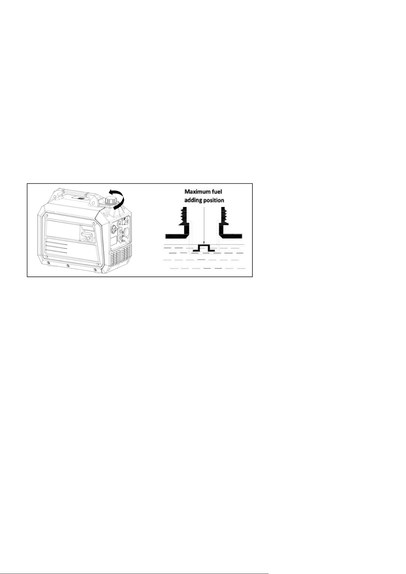
To add gasoline, follow these steps:
1. Make sure the generator stopped and cooled entirely,also make sure it is on a level surface.
2. Unscrew fuel cap anticlockwise slowly and set aside.
NOTE: The fuel cap may be tight and hard to unscrew.
3. Slowly add unleaded gasoline to the fuel tank. Be sure not to fill above the upper limit mark (the red
insert). Always allow room for fuel expansion. The capacity of the fuel tank is 1.3gallon.
4. Install the fuel cap.
NOTE: Do not fill the fuel tank to the very top. Gasoline will expand and spill over during use even with
the fuel cap in place. Reinstall fuel cap and wipe clean any spilled gasoline with a dry cloth.
IMPORTANT:
● Do not fill tank indoors.
● Do not fill tank when the engine is running or hot.
● Never use an oil/gasoline mixture.
● Never use old gasoline.
● Avoid getting dirt or water into the fuel tank.
● Gasoline can age in the tank and make starting difficult. Never store generator for extended periods of
time with fuel in the tank or the carburetor.
● Turn the fuel cock off and drain the fuel from the carburetor.
● Never use engine or carburetor cleaner products in the fuel tank or permanent damage may occur.h
● It is important to prevent gum deposits from forming in essential fuel system parts, such as the
carburetor, fuel filter, fuel hose or tank during storage. Also, experience indicates that alcohol-blended fuels
(called gasohol, ethanol or methanol) can attract moisture, which leads to separation and formation of acids
during storage.
● Acidic fuel can damage the fuel system of the generating set while in storage. Be sure to review the
instruction given in “Storage” section.
● Gasoline/ Alcohol Blends: up to 10% alcohol, 90% unleaded gasoline by volume is approved as a fuel.
Other gasoline/alcohol blends are not approved.
● Effects of old, stale or contaminated fuel are not warrantable.
● Allow the generating set to cool for at least two minutes before removing fuel cap when adding fuel.
● Loose the fuel cap slowly to relieve any pressure in the tank.
● Fuel and vapors are extremely flammable and explosive. Add fuel in a well ventilated area. Keep fire
and spark away. Failure to do so will result in death or serious injury!

15
Generator Set Grounding
DANGER: Failure to properly ground the generator can result in electric shock.
The generator must be properly connected to an appropriate ground. It helps prevent electrical shock if a
ground fault condition exists in the generating set or in connected electrical devices, especially when the
unit is equipped with a wheel kit. Proper grounding also helps dissipate static electricity, which often
builds up in underground devices.
A ground terminal has been provided on the generating set. For remote grounding, connect of a length of
heavy gauge(4mm
2
12 AWG minimum) copper wire between the generating set ground terminal and a
copper rod driven into the ground.
Local electrical codes may also require proper grounding of the unit. We strongly recommend that you
consult with a qualified electrician for grounding requirements in your area.
Neutral Floating*
–– Neutral circuit IS NOT electrically connected to the engine crankcase/ground of the inverter generator.
–– The generator (stator winding) is isolated from the engine crankcase and from the AC receptacle ground
pin.
–– Electrical devices that require a grounded receptacle pin connection will not function if the receptacle
ground pin is not functional.
Neutral Bonded to Frame*
–– Neutral circuit IS electrically connected to the frame/ground of the generator.
–– The generator system ground connects lower frame cross-member below the alternator. The system
ground is connected to the AC neutral wire.
* See your model’s control panel for specified type of grounding.
Electrical Devices
Disconnect all electrical devices from the generator and switch off the AC circuit breaker before start the
engine.
The generator may be hard to start with electrical devices.
The connected electrical equipment must not exceed the maximum limit of the generator. Please refer to the
specification table for details.
NOTE: After completing the above preparation, the generator is ready to be started.
16
GENERATOR OPERATION
Generator Start
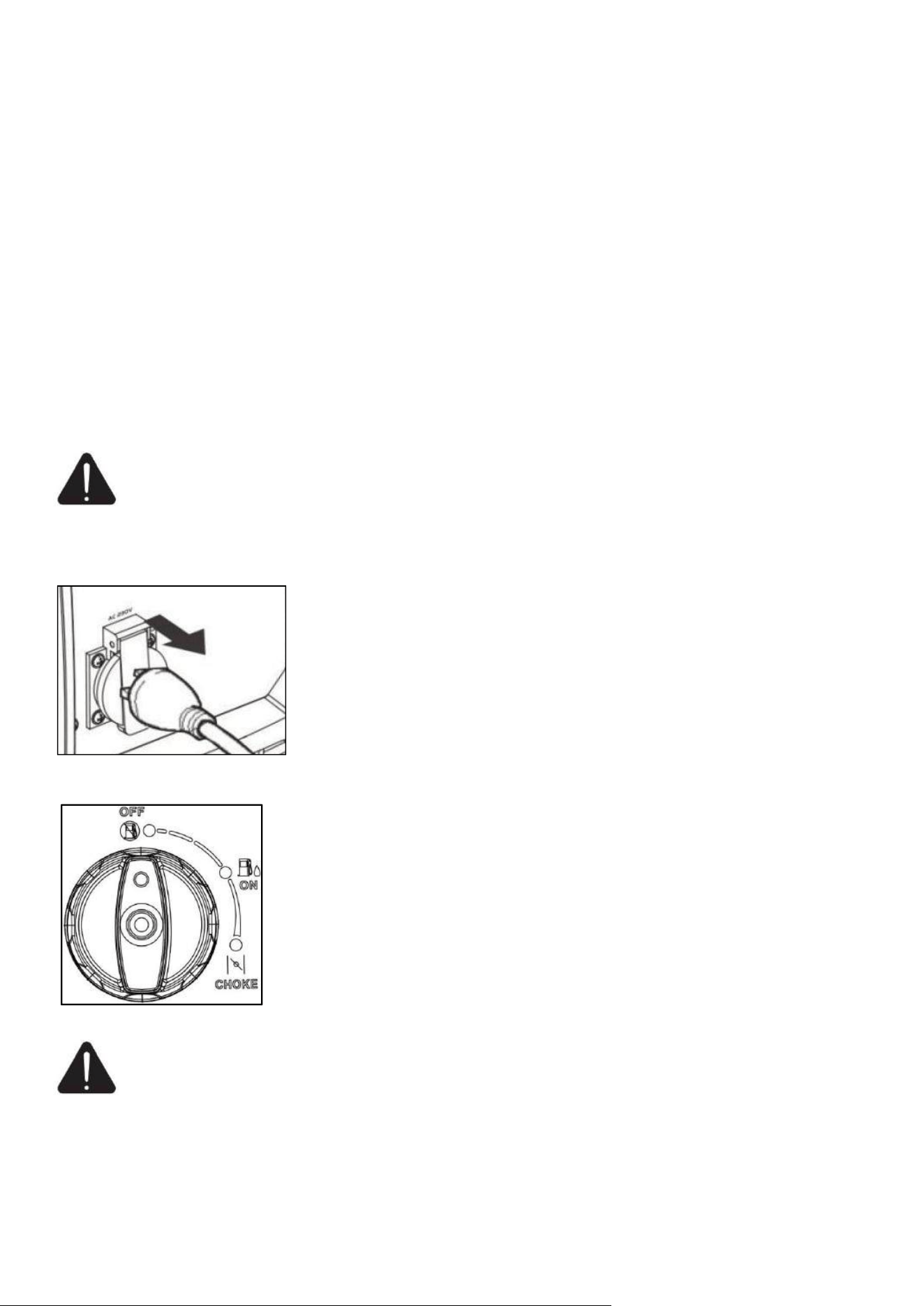
● Disconnect the electrical equipment from the alternator's AC socket before starting the engine.
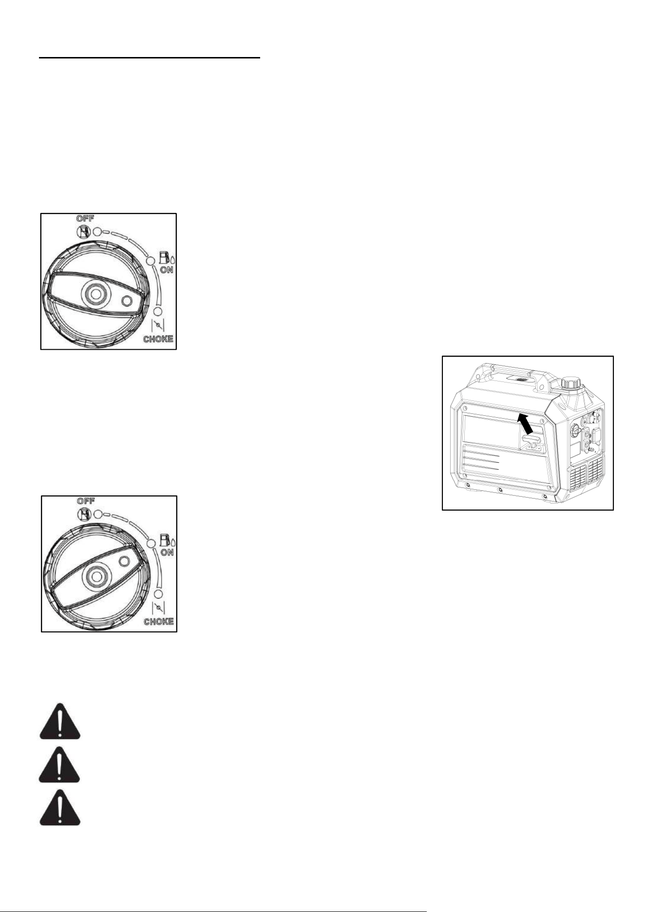
Make sure that the ECO switch is on “OFF”position.
● For initial use (long unused, start after gasoline is used up), turn the engine switch knob to "ON"
position for 10 to 20 seconds before starting, so that gasoline can enter the engine carburetor.
1. Turn the engine switch knob to the "CHOKE" position.
2. Grasp the recoil starter handle and pull slowly until resistance is felt, and
then pull rapidly to avoid kickback. Firmly grasp the generator to avoid
tumble of generator.
NOTE: Pay attention to pull the starting handle, the pull angle should not be
too large, to prevent the handle from wearing the housing.
Do not allow the starting handle to rebound and retract automatically to
avoid damage to the shell. Slowly put the starting handle back.
3. When the engine is running, wait about 5 second, then turn the engine
switch to the “ON” position.
4. After all above operations, the engine can be normally loaded.
NOTE: If engine fires, but does not continue to run, rotate the engine switch to “OFF” position and
repeat starting instructions to restart the generator.
WARNING: Check starter cord conditions before operating. Have it replaced immediately by
local authorized dealer if cord is frayed.
WARNING: Do not connect device to the panel before generator start. The device should be in
off position when it is connecting to the generator.
WARNING: Do not overload generator or individual panel receptacles. If an overload occurs,
the overload LED will illuminate and AC output ceases. To correct, unplug your loads, then
press MENU button for 3 seconds to reset as per Page 9.
17
Using The Generator
WARNING: It is prohibited to start or close the generating set when the output terminal of
generating set is connected to an electric device is in “ON” state.
Connect to electrical devices
● Inspect power cord for damage before using. There is a hazard of electrical shock from crushing, cutting
or heat damage.
● Make sure that the generating set has been properly grounded. If the electric devices require grounding,
the generating set must ground.
● Make sure that the electric devices are in “OFF” position.
● Allow the engine to stabilize and warm up for a few minutes after starting.
● Connect and start the electric devices.
● Turn off all electric devices and disconnect them from the generating set.
● If the generating set supplies for several loads or electric devices, start the smallest one first and the
largest one last.
DANGER: If connected devices overheat, turn them off and disconnect them from generating set.
Electrical Shock
To reduce the risk of electrical shock, DO NOT use electrical cords that are worn, frayed, bare or otherwise
damaged. DO NOT touch bare wires or receptacles. DO NOT handle generating set or electrical cords
while standing in water, while barefoot, or while hands or feet are wet.
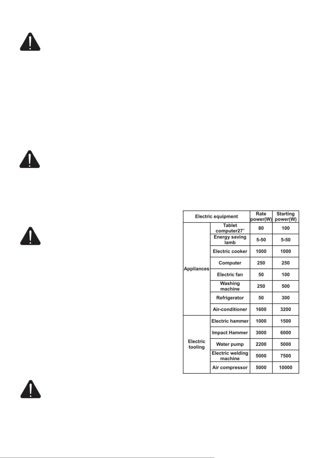
Loading Capacity
WARNING: Do not overload the generating set.
Exceeding the generating set’s capacity can
damage the generating set and/or electric devices
connected to it.
You must make sure your generating set can supply
enough rated (running) and (starting) watts for the
electrical devices at the same time. Follow these simple
steps to calculate the running and starting watts necessary
for your purposes.
1. Count the electrical devices you will power at the same
time.
2. The amount of power you need to run with the devices
is the total rated (running) watts of these items.
3. Starting power is the power needed shortly when
electric devices start. Since not all devices start at the
same time, starting power can be estimated by the
maximum power of all devices plus the total power
counted in step 2.
WARNING: It is necessary to equip with circuit protector or switch to isolate the generating set
from the electric utility when the generating set is mainly used for backup. Failure to isolate the
generating set from the power utility may result in injury or death to electric utility workers and damage to
the generating set due to back feed of electrical energy.
When using AC power, you can use DC power at the same time. If using both AC and DC output sockets,
Wattage Reference Chart
18
note that the total power does not exceed the sum of AC and DC power.
DC application
The output voltage of DC socket is 15-20 V, for 12V DC load only.
● When AC power is used, DC power supply can be used.
● Overload of DC may make DC over protector act. Firstly, remove the DC load, wait for a few minutes,
and then reset the button of DC protector.
AC application
1. Start the engine, make sure the AC output light (green) is on.
2. Turn off the power supply switch and plug the device into the generator's output socket.
NOTE: In order to obtain the best operation effect and the maximum service life of the generator, the new
generator should run for at least 20 hours under 50% load, so that the engine performance can be optimized.
Stop The Generator
WARNING: Never stop the engine with electrical devices connected and with the connected devices in
“ON” position.
1. Switch off the connected electrical appliances, and remove the connectors of all electric equipment from
the generating set panel.
2. Turn the engine switch to “OFF” position.
WARNING: Be sure the Engine Switch locate the “OFF” position, when stopping, transporting
and storing the generator.
19
MAINTENANCE
The purpose of maintenance and periodic maintenance is to keep the generator in the best operating condition.
When the maintenance indicate is flashing, please maintenance your generator in time!
W
ARNING: Improper maintenance or failure correct a problem before operation can cause a
m
alfunction and result in property damage, serious injury or DEATH. lease use our original
spare parts or the same quality parts when replacing damaged parts.Improper maintenance will void your
warranty.
D
ANGER: Accidental starts can cause severe injury or death. Remove the spark plug cap and
g
round generating set before performing any service.
W
ARNING: The filter element may contains PAHs, PAHs are harmful for your health. Please
w
ear gloves for protection during air filter maintenance.
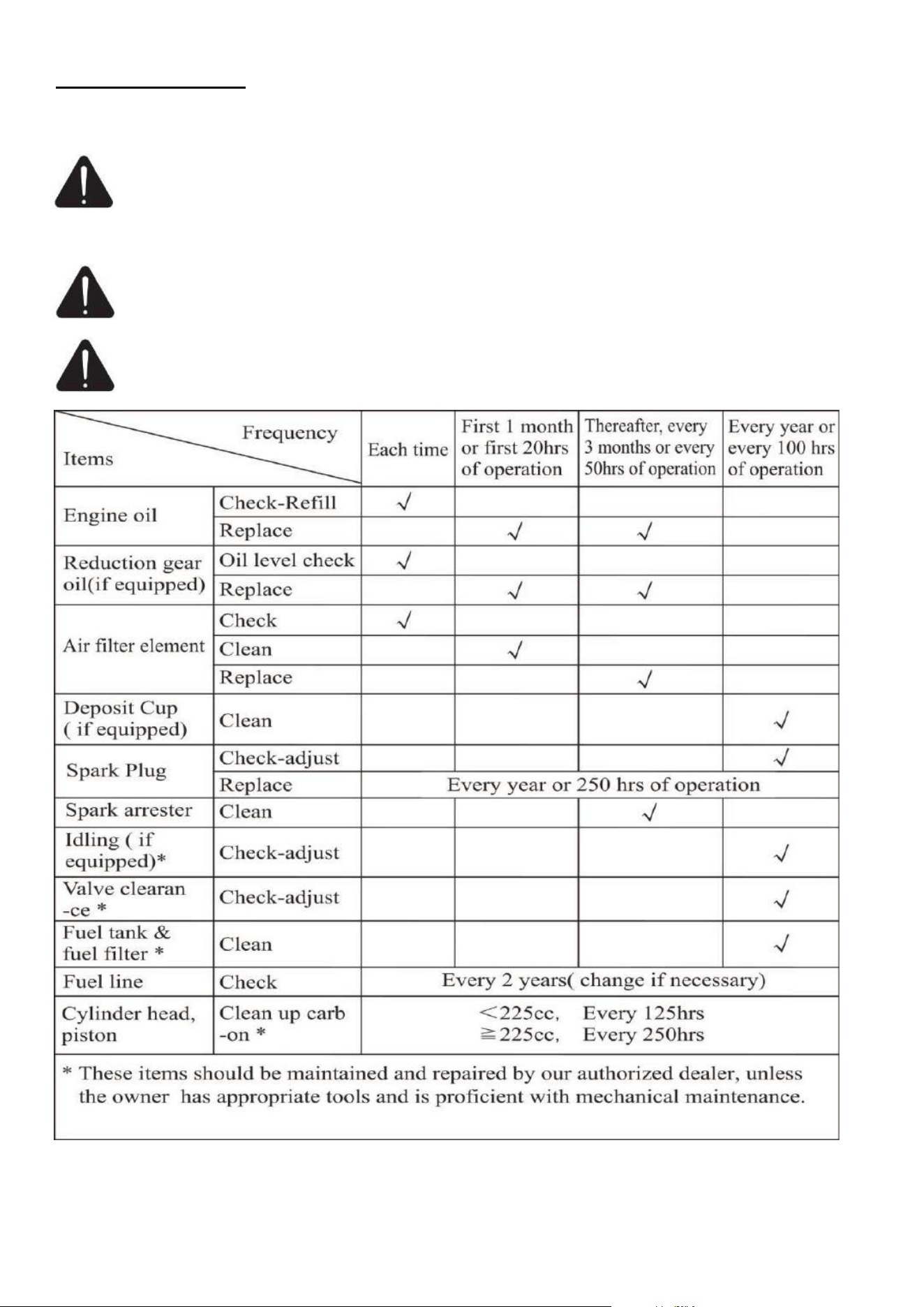
● If the gasoline engine frequently works under high temperature or heavy load, change the oil every 25
hours.
Maintenance Schedule
20
● If the engine frequently work under dusty or other severe circumstances, clean the air filter element
every 10 hours; If necessary, change the air filter element every 25 hours.
● If maintenance period and the exact time(hour), the one which comes first should govern.
● If you have missed the scheduled time to maintain your engine, do it as soon as possible.
Generator Maintenance
W
ARNING: Never clean the generator when it is running! Never use water to clean the
g
enerating set. Water can enter the generating set through the cooling slots and damage the
generating set windings.
W
ARNING: Do not modify the generator in any way. Do not tamper with governed speed.
G
enerator supplies correct rated frequency and voltage when running at factory set. Tampering
w
ith the factory set governor will void your warranty.
● Make certain that the generator is kept clean and stored properly.
● Use a dry cloth to clean exterior surfaces of the generating set. Use a soft brush to clean the dirt and
oil.
● Use an air compressor (25 PSI) to clear dirt and debris from the generating set.
● Inspect all air vents and cooling slots to ensure that they are clean and unobstructed.
Changing th e oil
W
ARNING: Change the oil when the engine is warm form operation. The oil can reach up to
1
40℃under that condition. Careful operation should be taken to prevent burns.
1. Place the machine on a level surface which is about 300mm high
away from the ground.
2. Loosen the cover screw and remove the cover as shown in the right
figure.
3. Place the waste oil box on the ground.
4. Remove the oil dipstick, and tilt the machine to pour the dirty oil
out.
5. Add recommended oil to the upper limit(H) of the dipstick.
6. Reinstall the dipstick tightly.
7. Properly dispose of any used
oil at an approved waste management facility.
8. Reinstall the oil maintenance cover.
For conforming to the environment requirement, the used oil will be put into a sealed container and then be
transported to the service station for recycle. Do not throw it into the trash or pour it on the ground.
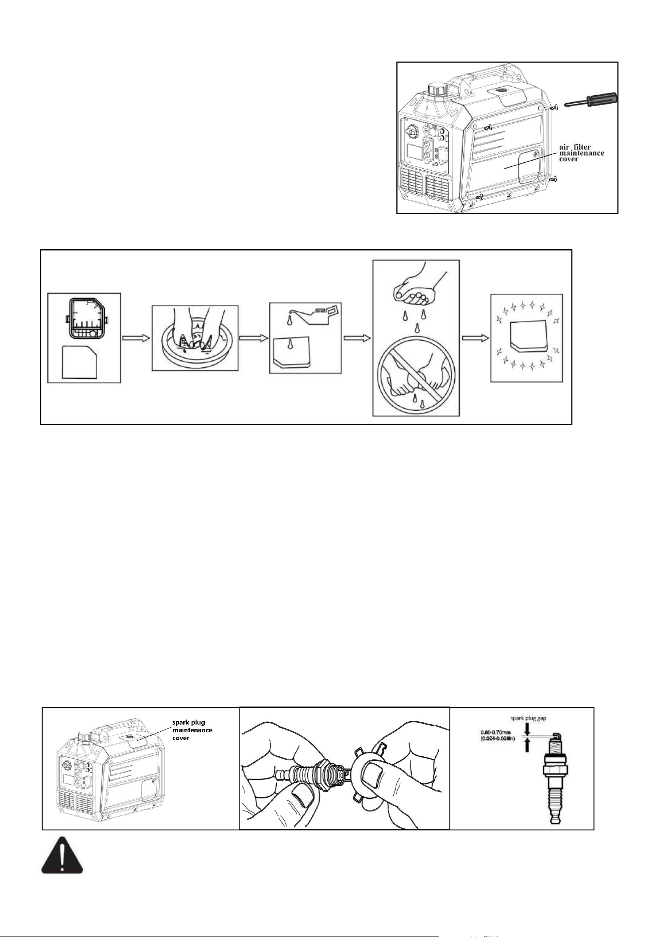
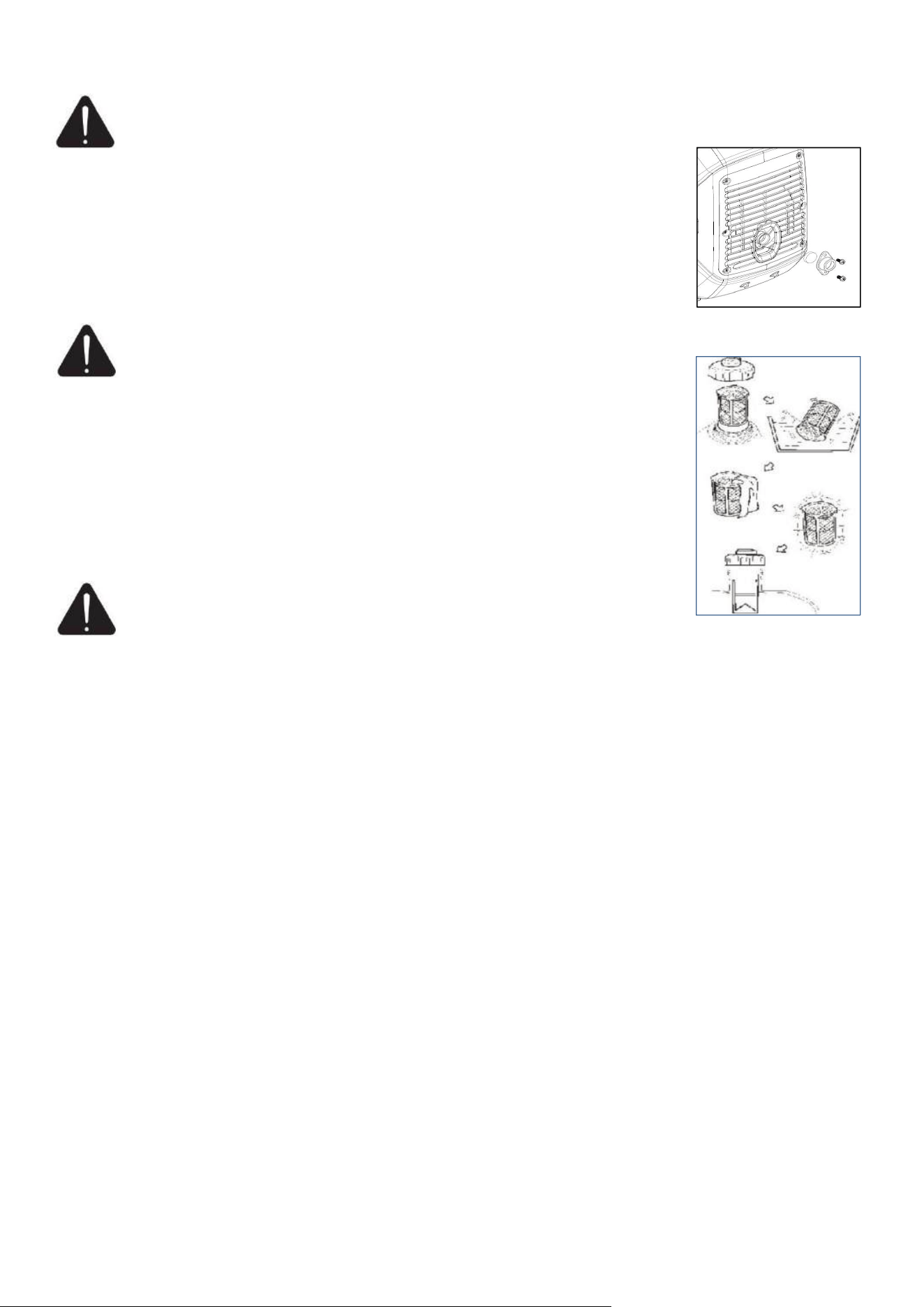
Air Filter Maintenance
WARNING: Do not run the engine without the air filter, or serious danger can result.
A dirty Air Cleaner will restrict air flow into the carburetor. Please clea
n and maintain the air
cleaner regularly to prevent carburetor from breaking down,If generators are often used in high dust areas,
21
they need to be maintained more frequently.
1. Loosen the cover screw and remove the air filter
maintenance cover.
2. Unscrew the bolt on the air filter cover and remove the cover
of the air filter.
3. Remove the foam filter element.
4. Wash in liquid detergent and warm water.
5. Squeeze thoroughly dry in a clean cloth(DO NOT TWIST).
6. Saturate in clean engine oil.
7. Squeeze in a clean absorbent cloth to remove all excess oil.
8. Assemble the filter element onto the filter unit.
9
. Assemble the filter fix clamp.
10. Reinstall the air filter cover and the air filter maintenance cover.
Spark Plug Maintenance
Spark plug gap : 0.6mm-0.7mm(0.024-0.028 in). Spark plug tighten torque: 12.5N.m
The spark plug is important for proper engine operation. A good spark plug should be intact, free of
deposits, and properly gapped. Refer to Recommended Maintenance Schedule. To inspect the spark plug:
1. Remove the spark plug maintenance cover, and take off the spark plug cap.
2. Using the spark plug spanner to loose and take off the spark plug.
3. Check the spark plug, if the spark plug insulator cracked or chipped, change a new one. Clean any dirt
from the spark plug cap and spark plug base with wire brush if reuse it.
4. Measure the spark plug gap with a standard gauge. The normal value should be:0.6-0.7mm (0.024-
0.028in), adjust if necessary.
5. Carefully thread the spark plug into the engine by hand.
6. After the spark plug is seated, use spark plug wrench to tighten the plug.
7. Attach the spark cap to the plug and connect the spark plug wire to the plug.
C
AUTION: Only use recommended spark plug or equivalent. Do not use spark plugs that have
i
mproper heat range.
22
Spark Collector Maintenance
W
ARNING: The spark collector must be maintained for every 100 hours of engine operation.
1. When the muffler is cooled, loosen the screws from the muffler outlet and take
off the spark collector.
2. Use a brush to clean the carbon deposits on the spark collector. If the spark
collector is damaged, and replace it.
3. Re-install the spark collector.
Fuel Tank Filter Maintenance
W
ARNING:Never use the gasoline while smoking or in the vicinity of an open flame.
1. Remove the fuel tank cap and filter.
2. Clean the filter with gasoline.
3. Wipe the filter and install it.
4. Install the fuel tank cap.
NOTE: Be sure the fuel tank cap is tightened securely.
Transport And Storage
W
ARNING: Gasoline is highly flammable and extremely explosive.
E
mpty the fuel tank before storing or transporting this generating set.
To prevent fuel spillage when transporting or during temporary storage, the generating set should be
secured upright in its normal operating position, with the engine switch OFF. The combination switch
should be in the “stop” position.
When transporting
● Do not overfill the tank.
● Do not operate the generating set while it is on vehicle. Take the generating set off the vehicle and use
it in a well-venti
lated place. Avoid a place exposed to direct sunlight when putting the generating set on a
vehicle. If the generating set is left in an enclosed vehicle for many hours, high temperature inside the
vehicle could cause fuel to vaporize resulting in a possible explosion.
● The generator must not be transported a long time on rough road. If you have to drive on a road like
this,drain off the gasoline and oil beforehand.
When storage for a long period
The generating set should be started at least once every 2 weeks and allowed to run for at least 20 minutes.
Follow the instructions below for longer term storage if the generating set will be out of service for 2
months or more.
● Allow the generating set to cool completely before storage.
● Clean the generating set according to instruction in maintenance section.
● Drain all fuel completely from the fuel tank, fuel hose and carburetor to prevent gum from forming.
● Turn engine switch to OFF position.
● Change the
oil.
● Reattach the spark plug.
● Remove the spark plug and pour about 15ml of oil into the cylinder.Crank the engine slowly to
distribute the oil and lubricate the cylinder.
● Store the unit in a clean, dry area out of direct sunlight.
23
TROUBLESHOOTING
Failure
Trouble
Solution
Generator fails to
start.
The engine switch is in
OFF position.
Turn the switch to on position.
Lack of fuel. Fill fuel tank with recommend fuel.
Lack of engine oil.
Check oil level. This engine is equipped with a low
oil sensor. The engine cannot be started unless the
oil level is above the prescribed lower limit.
No ignition. Defective
spark plug.
Check spark plug. Remove the spark plug cap. Clean
any dirt around the plug base, and then remove the
spark plug. Install the spark plug in the plug cap.
Turn the engine switch to“ON” position. Grounding
the electrode to any engine ground, pull the recoil
starter to see if sparks jump across the gap. If there is
no spark, replace the plug. Reinstall the plug and
start engine according to instructions in this manual.
Consult Customer Service if necessary.
Plugged fuel filter.
Replace the fuel and fuel filter.
Engine switch is broken.
Contact customer service.
Carburetor is flooded.
Drain carb.
Generator has no
AC output.
The breaker trip.
Unplug appliance, press the AC breaker button.
(120V 20A only)
Inadequate cord sets or
extension cords.
Check cord sets or extension cords capabilities in
section cords.Consult Customer Service if necessary.
Generator overloaded.
Reduce loads, then press and hold the MENU button
to reset.
Or unplug the loads, stop the generator, reduce loads
and restart the generator.
Short circuit in electrical
device.
Verify condition of extension cords and items being
cord.
Press and hold the MENU button to reset.
Defective inverter
assembly.
Contact customer service.
Generator flames
out after running
for a certain time.
Out of fuel or oil.
Check the fuel/oil level, add them if necessary.
The generator is closed to
overload.
Unplug loads, restart the generator and reduce loads.
Engine will not
start, or starts and
run rough.
Choke is stuck or left on. Turn the engine switch to CHOKE position.
Dirty or clogged air filter. Clean or replace the air filter.
Dirty or defective spark
plug.
Check the spark plug, clean or replace it.
Dirty fuel filter. Replace fuel and fuel filter.
Dirty or gummed up
carburetor.
Clean carburetor.
Unit not warmed up.
Gradually adjust engine switch, reduce choke until
engine runs smoothly in ON position.
Spark arrestor clogged. Clean spark arrestor of muffler.
Fuel leaks from
drain hose.
Carburetor drain in bowl is
not closed.
Turn the engine switch to OFF position.
24
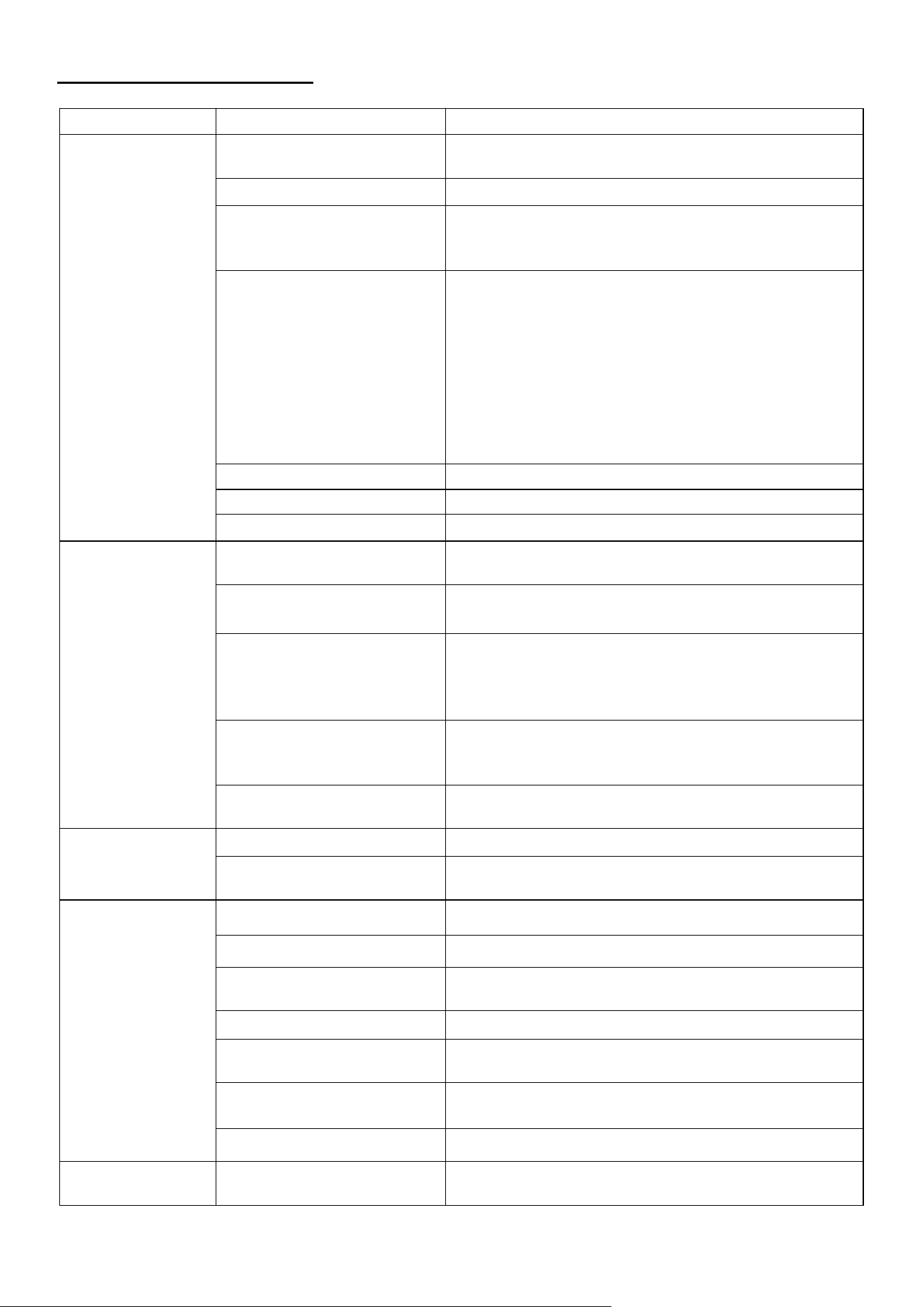
WIRING DIAGRAM
25
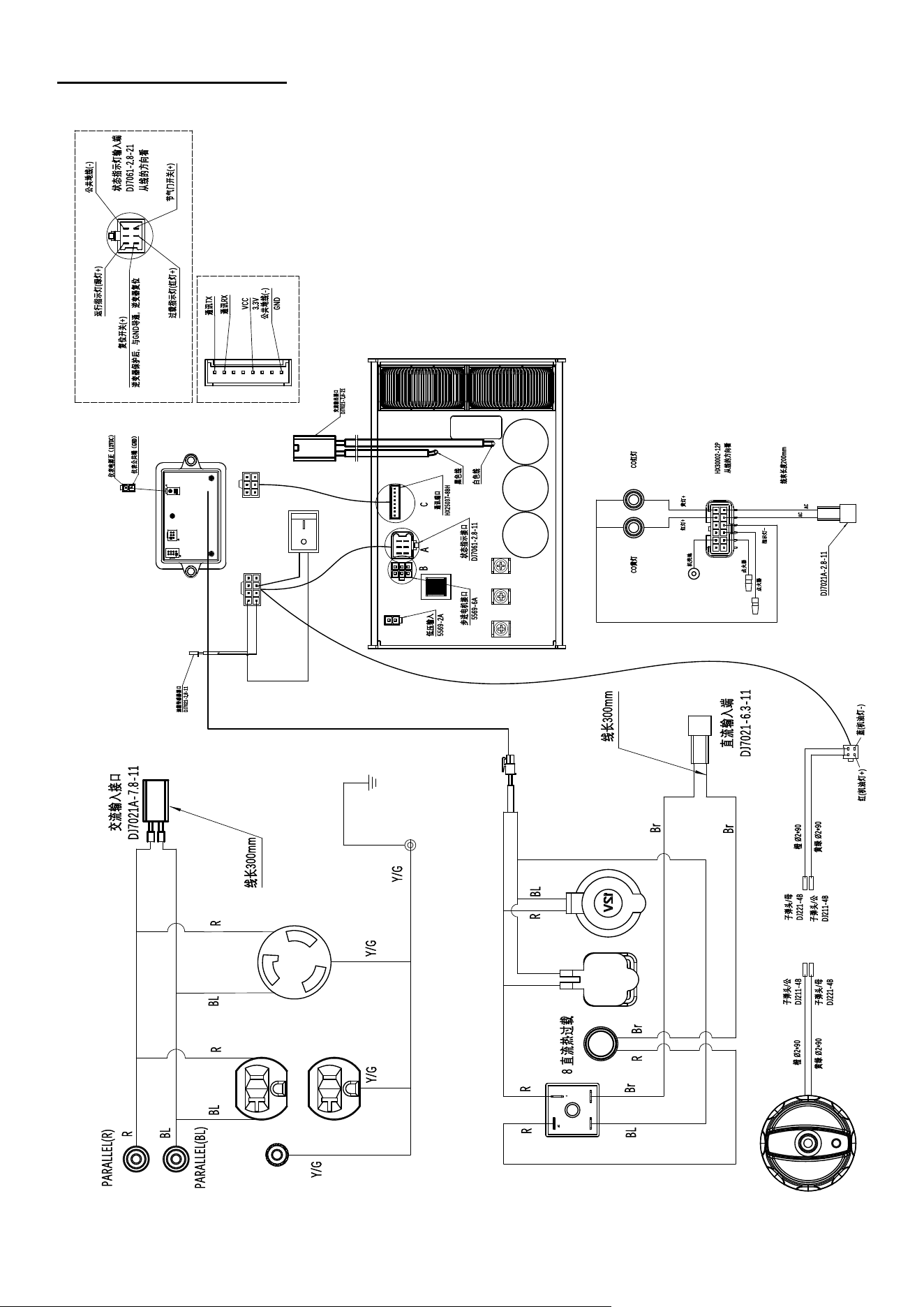
EXPLODED VIEW & PARTS L IST
Generator Exploded View & Part Lis t

26
NO.
1
2
3
4
5
6
7
8
9
10
11
12
13
14
15
16
17
18
19
20
21
22
23
24
25
26
27
28
29
30
31
32
CODE
026160003700
026160003821
511200402005
026310100033
511200501205
517110401601
511200601605
026310002100
517050401204
029993100401
026310000700
511200501205
512040600001
511050601401
029031100821
511200501205
029930003001
026160002600
029019900408
029019902103
029019900401
012440000004
518060500000
026310001000
026310000900
511200601605
026160002821
511200501005
512030500000
026310002021
511200501605
026310001600
DESCRIPTION
KNOB
KNOB COVER
SCREW M4X20
PANEL ASSEMBLY
SCREW M5X12
SCREW ST4X16
SCREW M6X16
PANEL BACK COVER
SCREW ST4X12
CO SENSOR
INVERTER BRACKET
SCREW M5X12
NUT M6
SCREW M6X14
INVERTER
SCREW M5X12
GROUND WIRE
THREE IN ONE SWITCH
FUEL HOSE CLAMP 7
FUEL LINE
FUEL HOSE CLAMP 8
UP165A ENGINE
FLAT PAD
MUFFLER COVER SEAL
MUFFLER SHIELD
SCREW M6X16
RECOIL HANDLE
SCREW M5X10
NUT M5
PULL ROPE GUIDE PLATE
SCREW M5X16
LEFT PANEL
QTY.
1
1
1
1
4
3
6
1
2
1
1
2
2
2
1
1
1
1
1
0.2
1
1
4
1
1
6
1
2
2
1
4
1
NO.
33
34
35
36
37
38
39
40
41
42
43
44
45
46
47
48
49
50
51
52
53
54
55
56
57
58
59
60
61
62
63
64
CODE
026160002200
026310001721
026030000300
511050601201
026310001500
026160001300
026310300001
02901990040302
029019905803
029019900408
029019900408
029019900100
026310003800
511200501605
026310000300
512140500005
026310000400
511200501605
026310001300
026160002200
026310001421
026030000300
511050601201
026160000400
026310000200
026150000500
026030000300
026310000100
512040600001
026310000500
513040600000
511050601401
DESCRIPTION
NUT M6
LEFT SKELETON
LOCK CLIP M6
SCREW M6X12
OIL CHANNEL
FUEL TANK SHOCK ABSORBER PAD
FUEL TANK
FUEL HOSE CLAMP 11
FUEL LINE
FUEL HOSE CLAMP 7
FUEL HOSE CLAMP 7
FUEL LINE
CHECK VALVE
SCREW M5X16
SPARK PLUG COVER
STOP BOLT M5
OIL PANEL
SCREW M5X16
RIGHT PANEL
SCREW M6X12
RIGHT SKELETON
LOCK CLIP M6
SCREW M6X12
SHOCK ABSORPTION BEARING
SHOCK ABSORPTION BEARING BRACKET
NUT 16X16X5_M6
LOCK CLIP M6
BOTTOM PLATE
NUT M6
FRAME SHOCK ABSORBER PAD
FLAT WASHER 6
SCREW M6X14
QTY.
3
1
4
2
1
4
1
1
1
1
1
0.4
1
4
1
1
1
4
1
3
1
4
4
4
1
6
4
1
4
4
4
4
27
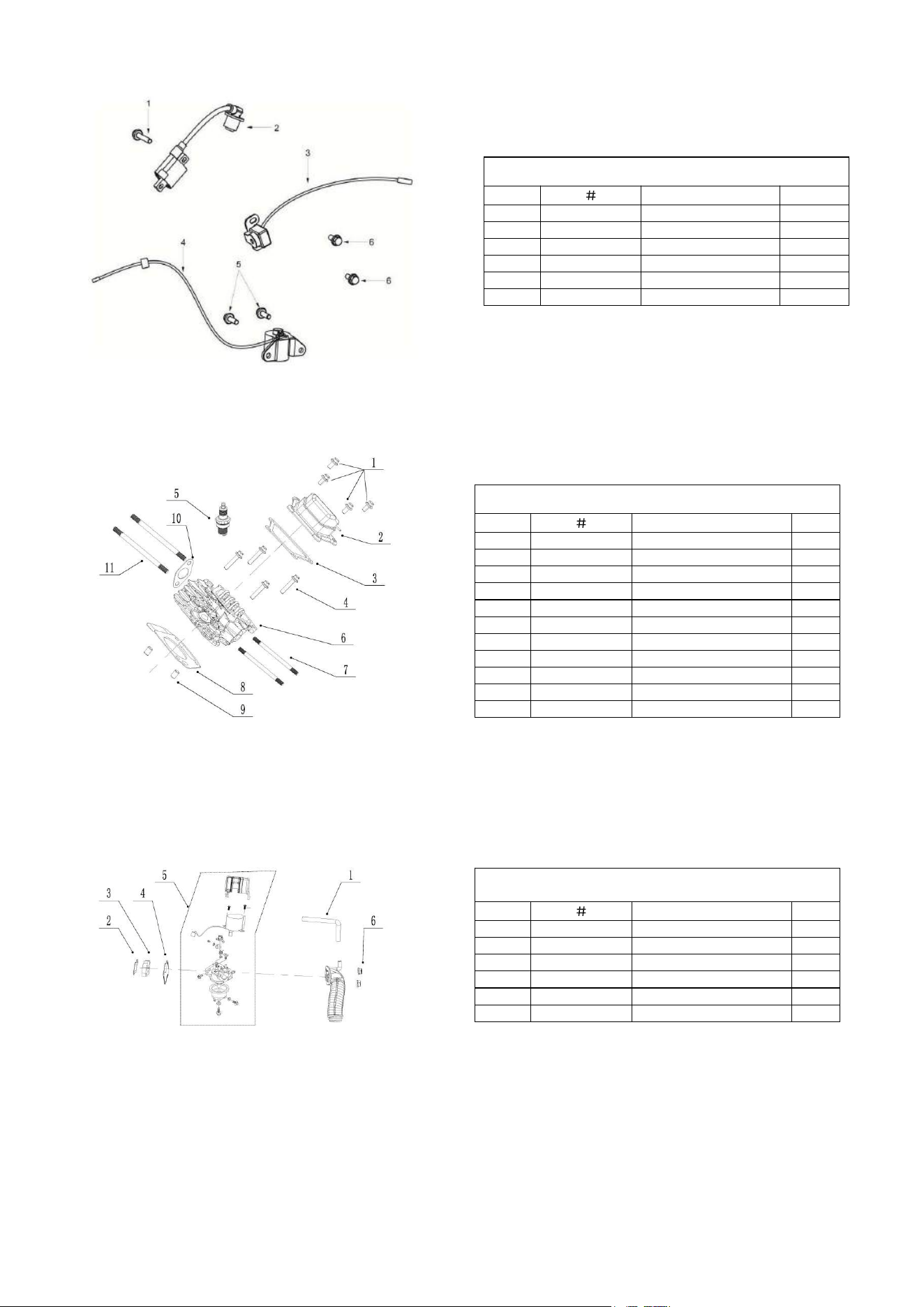
Engine Explode View &Part List
IGNITER ASSEMBLY
Item
Stock
#
Description
Qty
1
517050401800
Bolt ST4.8X18
2
2
012440000200
Igniter coil
1
3
012440000100
Trigger coil assembly
1
4
012440003100
Oil alarm
1
5
511050601201
Bolt M6×12
2
6
511130601801
Bolt M6x18
2
CYLINDER HEAD PARTS
Item
Stock
#
Description
Qty
1
511130601801
Bolt M6x18
4
2
012440400000
Cover sub assembly
1
3
012440001900
Cylinder head cover pad
1
4
511050806006
Bolt M8x60
4
5
012440001100
Spark plug
1
6
012440001700
Cylinder head
1
7
516040609401
Stud bolt
2
8
012440001800
Gasket-Cylinder head
1
9
514011001600
Pin
2
10
012440002900
Exhaust port gasket
1
11
516050809201
Stud bolt
2
CARBURETOR PARTS
Item
Stock
#
Description
Qty
1
019990004000
Exhaust pipe
1
2
012440001200
Air inlet gasket
1
3
012440000700
Carburetor block
1
4
012440000800
Carburetor gasket
1
5
012440100001
Carburetor
1
6
512040600001
Nut
2
28
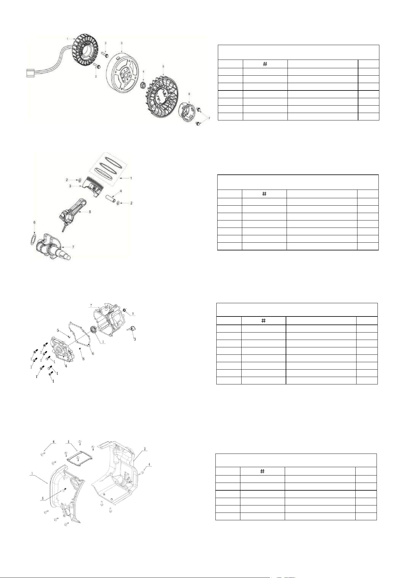
ELECTRICAL COMPONENTS
Item
Stock
#
Description
Qty
1
3VDZ460402
Motor stator
1
2
511130605501
Bolt M6×55
4
3
3VZZ460401
Motor rotor
1
4
012010002300
Nut
1
5
012440000300
fan
1
6
012440001600
Starting sleeve
1
7
511130601801
Bolt M6x18
2
PINTON, CONNECTING ROD, CRANKSHAFT
Item
Stock
#
Description
Qty
1
012440200000
Ring as piston
1
2
518041200002
Piston pin circlip
2
3
012440000900
Piston
1
4
012440001000
Piston pin
1
5
012440300000
Connecting rod assembly
1
6
012440002400
Wear resistant gasket
1
7
012440600000
Crankshaft assembly
1
CRANKCASE
Item
Stock
#
Description
Qty
1
511130602501
Bolt M6X25
8
2
521010012602
Bearing
1
3
012020200000
Dipstick assembly
1
4
012440002500
Crankcase cove
1
5
514010801200
pin
2
6
012440002600
Crankcase gasket
1
7
012440002700
Crankcase
1
8
522010101901
Oil seal
1
WIND SCOOPER
Item
Stock
#
Description
Qty
1
012440000400
right wind scooper
1
2
012440000500
Left wind scooper
1
3
012440000600
wind scooper cover
1
4
511050601201
Bolt M6X12
3
5
511050601801
Bolt M6X18
1
6
517050401800
Bolt ST4.8X18
9
29
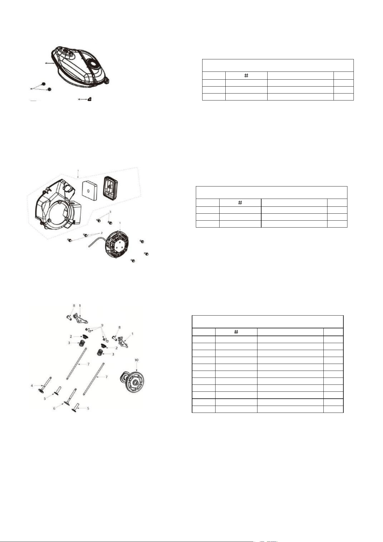
MUFFLER PARTS
Item
Stock
#
Description
Qty
1
012440002800
Muffler
1
2
512040800001
Nut
2
3
511050607001
Bolt M6X70
1
ENGINE STARTER
Item
Stock
#
Description
Qty
1
012440700000
Engine Starter
1
2
511050604001
Bolt Mx40
2
3
511050601801
Bolt Mx18
2
CAMSHAFT PARTS
Item
Stock
#
Description
Qty
1
012440500000
Rocker arm assembly
2
2
012440002000
Valve spring seat
2
3
012150003000
Valve spring
2
4
012440001500
Exhaust valve
1
5
012440002200
Tapper
2
6
012440001300
Intake valve
1
7
012440002300
Putter
2
8
012440003000
Rocker pin
2
9
012440002100
Valve clamp lock
4
10
012440800000
Camshaft components
1
11
012440001400
Oil baffle
1

30
TWO (2) YEARS LIMITED WARRANTY
Amerisun is committed to building tools that are dependable for years. Our warranties are consistent with our
commitment and dedication to quality.
TWO (2) YEARS LIMITED WARRANTY OF AMERISUN PRODUCTS FOR HOME USE.
Amerisun (“Seller") warrants to the original purchaser only, that all Amerisun consumer power tools will be free from
defects in material or workmanship for a period of two (2) years from date of purchase. Ninety (90) days for all
Amerisun Products, if the tool i
s used for professional or commercial use.
SELLER’S SOLE OBLIGATION AND YOUR EXCLUSIVE REMEDY under this Two (2) Years Limited Warranty
and, to the extent permitted by law, any warranty or condition implied by law, shall be the repair or replacement of
parts, without charge, which are defective in material or workmanship and which have not been misused, carelessly
handled, or misrepaired by persons other than Seller or Authorized Service Center. To make a claim under this
Limited Warranty, you must return the entire power tool product; transportation prepaid, to Amerisun include a legible
copy of the original receipt, which lists the date of purchase (month and year) and the name of the company purchased
from.
THIS LIMITED WARRANTY DOES NOT APPLY TO ANY ACCESSORY ITEMS INCLUDED WITH THE
TOOL SUCH AS CIRCULAR SAW BLADES OTHER RELATED ITEMS OR TO ANY REPLACEMENT PARTS
LISTED UNDER MAINTENANCE.
ANY IMPLIED WARRANTIES SHALL BE LIMITED IN DURAT
ION TO TWO (2) YEARS FROM DATE OF
PURCHASE. SOME STATES IN THE U.S. AND SOME CANADIAN PROVINCES DO NOT ALLOW
LIMITATIONS ON HOW LONG AN IMPLIED WARRANTY LASTS, SO THE ABOVE LIMITATION MAY
NOT APPLY TO YOU.
IN NO EVENT SHALL SELLER BE LIABLE FOR ANY INCIDENTAL OR CONSEQUENTIAL DAMAGES
(INCLUDING BUT NOT LIMITED TO LIABILITY FOR LOSS OF PROFITS) ARISING FROM THE SALE OR
USE OF THIS PRODUCT. SOME STATES IN THE U.S. AND SOME CANADIAN PROVINCES DO NOT
ALLOW THE EXCLUSION OR LIMITATION O
F INCIDENTAL OR CONSEQUENTIAL DAMAGES, SO THE
ABOVE LIMITATION OR EXCLUSION MAY NOT APPLY TO YOU.
THIS LIMITED WARRANTY GIVES YOU SPECIFIC LEGAL RIGHTS, AND YOU MAY ALSO HAVE OTHER
RIGHTS WHICH VARY FROM STATE TO STATE IN THE U.S., PROVINCE TO PROVINCE IN CANADA
AND FROM COUNTRY TO COUNTRY.
For questions / comments, technical assistance or repair parts –
Please call toll free at: 1-872-314-0005
(M-F 9am – 5pm EST)
Email:
SAVE YOUR RECEIPTS. THIS WARRANTY IS VOID WIT HOUT THEM.

31

32