
IMPORTANT: Your new tool has been engineered and manufactured to WEN’s highest standards for dependability,
ease of operation, and operator safety. When properly cared for, this product will supply you years of rugged,
trouble-free performance. Pay close attention to the rules for safe operation, warnings, and cautions. If you use
your tool properly and for its intended purpose, you will enjoy years of safe, reliable service.
NEED HELP? CONTACT US!
Have product questions? Need technical support? Please feel free to contact us:
TECHSUPPOR[email protected]1-847-429-9263 (M-F 8AM-5PM CST)
For replacement parts and the most up-to-date instruction manuals, visit WENPRODUCTS.COM
10-INCH CORDED
ELECTRIC POLE SAW
Instruction Manual
MODEL CP0810

CONTENTS
WELCOME 3
Introduction ......................................................................................................3
Specifications ....................................................................................................3
SAFETY 4
General Safety Rules .........................................................................................4
Pole Saw Safety Warnings ................................................................................6
Electrical Information ........................................................................................8
BEFORE OPERATING 9
Unpacking & Packing List .................................................................................9
Know Your Pole Saw .......................................................................................10
Assembly & Adjustments ................................................................................11
OPERATION & MAINTENANCE 15
Operation ........................................................................................................15
Maintenance ....................................................................................................17
Exploded View & Parts List .............................................................................18
Warranty Statement ........................................................................................20
2
To purchase accessories and replacement parts for your tool, visit WENPRODUCTS.COM

SPECIFICATIONS
INTRODUCTION
Thanks for purchasing the WEN Pole Saw. We know you are excited to put your tool to work, but first, please take
a moment to read through the manual. Safe operation of this tool requires that you read and understand this op-
erator’s manual and all the labels affixed to the tool. This manual provides information regarding potential safety
concerns, as well as helpful assembly and operating instructions for your tool.
NOTE: The following safety information is not meant to cover all possible conditions and situations that may occur.
WEN reserves the right to change this product and specifications at any time without prior notice.
At WEN, we are continuously improving our products. If you find that your tool does not exactly match this manual,
please visit wenproducts.com for the most up-to-date manual or contact our customer service at 1-847-429-9263.
Keep this manual available to all users during the entire life of the tool and review it frequently to maximize
safety for both yourself and others.
Indicates danger, warning, or caution. The safety symbols and the explanations with them deserve your
careful attention and understanding. Always follow the safety precautions to reduce the risk of fire, electric shock
or personal injury. However, please note that these instructions and warnings are not substitutes for proper ac-
cident prevention measures.
Model Number CP0810
Motor 120V, 60 Hz, 8A
Guide Bar 10 in.
Saw Chain 10 in.
Chain Links
40 Links
Maximum Cutting Capacity 10 in.
Extended Length 9 ft
No-Load Speed
6300 RPM
Chain Speed 35.5 ft/sec
Chain Gauge 0.05 in. (1.27mm)
Chain Pitch 0.4 in. (9.5mm)
Sharpening File Size
GCR15 0.2 in. x 9.6 in. (4mm x 245mm)
Oil Tank Capacity
2.5 fl. oz. (75 ml)
Oil Type
5W-30
Product Dimensions
108.3 in. x 3.2 in. x 5.5 in.
Product Weight 8.4 lbs
3

GENERAL SAFETY RULES
WORK AREA SAFETY
1. Keep work area clean and well lit. Cluttered or dark
areas invite accidents.
2. Do not operate power tools in explosive atmo-
spheres, such as in the presence of flammable liquids,
gases or dust. Power tools create sparks which may ig-
nite the dust or fumes.
3. Keep children and bystanders away while operating
a power tool. Distractions can cause you to lose control.
ELECTRICAL SAFETY
1. Power tool plugs must match the outlet. Never mod-
ify the plug in any way. Do not use any adapter plugs
with earthed (grounded) power tools. Unmodified plugs
and matching outlets will reduce risk of electric shock.
2. Avoid body contact with earthed or grounded surfac-
es such as pipes, radiators, ranges and refrigerators.
There is an increased risk of electric shock if your body
is earthed or grounded.
3. Do not expose power tools to rain or wet conditions.
Water entering a power tool will increase the risk of elec-
tric shock.
4. Do not abuse the cord. Never use the cord for car-
rying, pulling or unplugging the power tool. Keep cord
away from heat, oil, sharp edges or moving parts.
Damaged or entangled cords increase the risk of electric
shock.
5. When operating a power tool outdoors, use an ex-
tension cord suitable for outdoor use. Use of a cord
suitable for outdoor use reduces the risk of electric
shock.
6. If operating a power tool in a damp location is un-
avoidable, use a ground fault circuit interrupter (GFCI)
protected supply. Use of a GFCI reduces the risk of elec-
tric shock.
PERSONAL SAFETY
1. Stay alert, watch what you are doing and use com-
mon sense when operating a power tool. Do not use a
power tool while you are tired or under the influence
of drugs, alcohol or medication. A moment of inatten-
tion while operating power tools may result in serious
personal injury.
2. Use personal protective equipment. Always wear
eye protection. Protective equipment such as a respira-
tory mask, non-skid safety shoes and hearing protection
used for appropriate conditions will reduce the risk of
personal injury.
3. Prevent unintentional starting. Ensure the switch is
in the off-position before connecting to power source
and/or battery pack, picking up or carrying the tool.
Carrying power tools with your finger on the switch or
energizing power tools that have the switch on invites
accidents.
4. Remove any adjusting key or wrench before turning
the power tool on. A wrench or a key left attached to a
rotating part of the power tool may result in personal
injury.
5. Do not overreach. Keep proper footing and balance
at all times. This enables better control of the power
tool in unexpected situations.
6. Dress properly. Do not wear loose clothing or jew-
elry. Keep your hair and clothing away from moving
parts. Loose clothes, jewelry or long hair can be caught
in moving parts.
Safety is a combination of common sense, staying alert and knowing how your item works. The term “power tool”
in the warnings refers to your mains-operated (corded) power tool or battery-operated (cordless) power tool.
SAVE THESE SAFETY INSTRUCTIONS.
WARNING! Read all safety warnings and all instructions. Failure to follow the warnings and instructions may
result in electric shock, fire and/or serious injury.
4

GENERAL SAFETY RULES
7. If devices are provided for the connection of dust
extraction and collection facilities, ensure these are
connected and properly used. Use of dust collection
can reduce dust-related hazards.
POWER TOOL USE AND CARE
1. Do not force the power tool. Use the correct power
tool for your application. The correct power tool will
do the job better and safer at the rate for which it was
designed.
2. Do not use the power tool if the switch does not turn
it on and off. Any power tool that cannot be controlled
with the switch is dangerous and must be repaired.
3. Disconnect the plug from the power source and/or
the battery pack from the power tool before making
any adjustments, changing accessories, or storing
power tools. Such preventive safety measures reduce
the risk of starting the power tool accidentally.
4. Store idle power tools out of the reach of children
and do not allow persons unfamiliar with the power
tool or these instructions to operate the power tool.
Power tools are dangerous in the hands of untrained us-
ers.
5. Maintain power tools. Check for misalignment or
binding of moving parts, breakage of parts and any
other condition that may affect the power tool’s opera-
tion. If damaged, have the power tool repaired before
use. Many accidents are caused by poorly maintained
power tools.
6. Keep cutting tools sharp and clean. Properly main-
tained cutting tools with sharp cutting edges are less
likely to bind and are easier to control.
7. Use the power tool, accessories and tool bits, etc.
in accordance with these instructions, taking into ac-
count the working conditions and the work to be per-
formed. Use of the power tool for operations different
from those intended could result in a hazardous situa-
tion.
8. Use clamps to secure your workpiece to a stable
surface. Holding a workpiece by hand or using your
body to support it may lead to loss of control.
9. KEEP GUARDS IN PLACE and in working order.
SERVICE
1. Have your power tool serviced by a qualified repair
person using only identical replacement parts. This
will ensure that the safety of the power tool is main-
tained.
CALIFORNIA PROPOSITION 65 WARNING
Some dust created by power sanding, sawing, grinding,
drilling, and other construction activities may contain
chemicals, including lead, known to the State of Califor-
nia to cause cancer, birth defects, or other reproductive
harm. Wash hands after handling. Some examples of
these chemicals are:
• Lead from lead-based paints.
• Crystalline silica from bricks, cement, and other
masonry products.
• Arsenic and chromium from chemically treated
lumber.
Your risk from these exposures varies depending on
how often you do this type of work. To reduce your ex-
posure to these chemicals, work in a well-ventilated area
with approved safety equipment such as dust masks
specially designed to filter out microscopic particles.
5
Safety is a combination of common sense, staying alert and knowing how your item works. The term “power tool”
in the warnings refers to your mains-operated (corded) power tool or battery-operated (cordless) power tool.
SAVE THESE SAFETY INSTRUCTIONS.
WARNING! Read all safety warnings and all instructions. Failure to follow the warnings and instructions may
result in electric shock, fire and/or serious injury.

POLE SAW SAFETY WARNINGS
WARNING! Do not operate the power tool until you have read and understood the following instructions and
the warning labels.
POLE SAW SAFETY
1. TOOL PURPOSE. The purpose of this pole saw is for
limbing trees and cleaning up branches. Do not push it
beyond its limits or capacities. Using the pole saw in a
way for which it was not designed can result in serious
injuries, machine damage, and voiding of the warranty.
2. Hold the pole saw by the insulated gripping surfac-
es only. If the pole saw contacts a live wire, the exposed
metal parts of the pole saw may become liveand could
cause electric shock. Hold the pole saw with two hands
to avoid loss of control.
3. Keep all parts of the body away from the saw chain.
The saw chain continues to move after the switch is
turned OFF. Allow the saw chain to completely stop, and
remove the battery, before clearing jammed material.
4. Keep bystanders, especially children, at a safe dis-
tance away from the saw during operation.
5. Wear eye and hearing protection. Other personal
protection equipment for the head, hands, legs, and feet
is recommended especially when using the pole saw
overhead. Falling debris can result in serious injury.
6. Do not operate the saw while sitting or standing in a
tree. Maintain a safe, secure stance at all times. Only use
the saw when standing on solid, safe, and level ground.
7. Use particular caution when cutting brush and young
trees. The thin material may get caught in the chain and
hit you or throw you off balance.
8. Carry the powered OFF pole saw using the handle
with the chain pointing away from your body. Always
put on the protective cover and remove the battery when
transporting or storing the pole saw. Handling the saw
with care greatly reduces the risk of accidentally touch-
ing the sharp cutting chain.
9. Keep the handles dry, clean, and free from gas, oil,
and grease. Slippery handles may lead to a loss of con-
trol.
10. Remain alert; pay attention to what you are doing
and proceed sensibly when working with an electric
tool. Do not use the machine if you are tired or under the
influence of drugs, alcohol, or medication.
11. Inspect the saw thoroughly before use for any
damage. If any parts or pieces appear to be missing or
damaged, do not operate the saw.
12. Do not operate during adverse weather conditions,
particularly during lightening and rain. This decreases
the risk of being struck by lightning.
13. Sawing wood under tension requires an increased
amount of caution. Wood that is suddenly released from
tension can react in a completely uncontrolled manner.
This can result in severe to deadly injuries. Such work
may only be performed by trained specialists.
14. To reduce the risk of electrocution, never use near
any electrical power lines. Contact with or use near
power lines may cause serious injury or electric shock
resulting in death.
15. Always use two hands when operating the pole
saw. Hold the pole saw with both hands to avoid loss
of control.
16. Wait until the chain has come to a standstill com-
pletely before placing it down.
18. Any servicing should be performed by an autho-
rized service representative. If you need assistance,
contact WEN customer service at 1-847-429-9263.
6

POLE SAW SAFETY WARNINGS
REDUCING KICKBACK
Kickback can occur when the tip of the guide bar touches an object or when the wood closes in and pinches the saw
chain inside of the cut. Tip contact can kick the guide bar up and back towards the operator. Pinching the saw chain
along the top of the guide bar can push the bar rapidly towards the operator. Either of these reactions may cause a
loss in control of the pole saw, increasing the chances of serious personal injury. Do not rely on the safety devices
built into the saw. Pole saw users should take as many precautions as possible to minimize on-site accidents. Kick-
back is the result of tool misuse and/or incorrect operating procedures. These conditions can be minimized with the
following steps:
1. Maintain a firm grip, with thumbs and fingers encircling the pole saw handle. Both hands should be on the saw
with your body and arms in a position to resist kickback forces. Kickback forces can be controlled by the operator,
if proper precautions are taken. Do not let go of the pole saw.
2. Do not overreach and do not cut above shoulder height. This helps prevent unintended tip contact and enables
better control of the pole saw in unexpected situations.
3. Only use replacement bars and chains specified by WEN. Incorrect replacement bars and chains may cause chain
breakage and/or kickback.
4. Follow the manufacturer’s sharpening and maintenance instructions for the pole saw. Decreasing the depth gauge
height can lead to increased kickback.
7
WARNING! Do not operate the power tool until you have read and understood the following instructions and
the warning labels.

8
ELECTRICAL INFORMATION
AMPERAGE
REQUIRED GAUGE FOR EXTENSION CORDS
25 ft. 50 ft. 100 ft. 150 ft.
8A 18 gauge 16 gauge 14 gauge 12 gauge
IMPORTANT: Servicing a double-insulated product requires extreme care and knowledge of the system, and
should be done only by qualified service personnel using identical replacement parts. Always use original factory
replacement parts when servicing.
1. Polarized Plugs. To reduce the risk of electric shock, this equipment has a polarized plug (one blade is wider
than the other). This plug will fit in a polarized outlet only one way. If the plug does not fit fully in the outlet, reverse
the plug. If it still does not fit, contact a qualified electrician to install a proper outlet. Do not modify the machine
plug or the extension cord in any way.
2. Ground fault circuit interrupter protection (GFCI) should be provided on the circuit or outlet used for this power
tool to reduce the risk of electric shock.
3. Service and repair. To avoid danger, electrical appliances must only be repaired by a qualified service technician
using original replacement parts.
GUIDELINES AND RECOMMENDATIONS FOR EXTENSION CORDS
When using an extension cord, be sure to use one heavy enough to carry the current your product will draw. An
undersized cord will cause a drop in line voltage, resulting in loss of power and overheating. The table below shows
the correct size to be used according to cord length and ampere rating. When in doubt, use a heavier cord. The
smaller the gauge number, the heavier the cord.
DOUBLE-INSULATED TOOLS
The tool’s electrical system is double-insulated where two systems of insulation are provided. This
eliminates the need for the usual three-wire grounded power cord. Double-insulated tools do not need
to be grounded, nor should a means for grounding be added to the product. All exposed metal parts are
isolated from the internal metal components with protecting insulation.
1. Examine extension cord before use. Make sure your extension cord is properly wired and in good condition.
Always replace a damaged extension cord or have it repaired by a qualified person before using it.
2. Do not abuse extension cord. Do not pull on cord to disconnect from receptacle; always disconnect by pulling on
plug. Disconnect the extension cord from the receptacle before disconnecting the product from the extension cord.
Protect your extension cords from sharp objects, excessive heat and damp/wet areas.
3. Use a separate electrical circuit for your tool. This circuit must not be less than a 12-gauge wire and should be
protected with a 15A time-delayed fuse. Before connecting the motor to the power line, make sure the switch is in
the OFF position and the electric current is rated the same as the current stamped on the motor nameplate. Running
at a lower voltage will damage the motor.

9
UNPACKING & PACKING LIST
UNPACKING
With the help of a friend or trustworthy foe, such as one of your in-laws, carefully remove the pole saw from the
packaging and place it on a sturdy, flat surface. Make sure to take out all contents and accessories. Do not discard
the packaging until everything is removed. Check the packing list below to make sure you have all of the parts and
accessories. If any part is missing or broken, please contact customer service at 1-847-429-9263 (M-F 8-5 CST),
or email [email protected].
PACKING LIST
Description Quantity
Pole Saw Handle 1
Pole Saw Shaft 1
Pole Saw Head 1
Shoulder Strap 1
Sheath 1
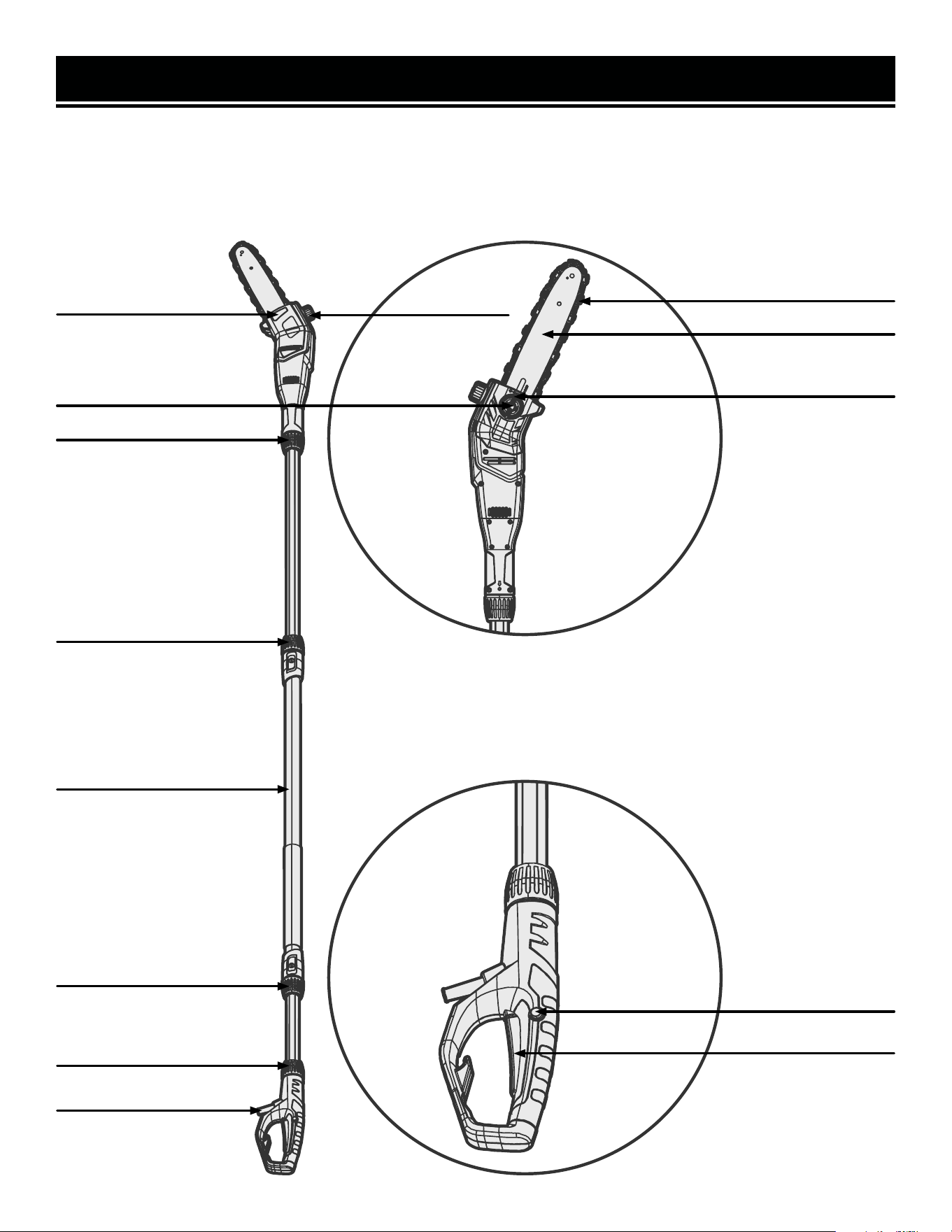
KNOW YOUR POLE SAW
TOOL PURPOSE
Easily limb trees and clean up branches with your WEN 20V Pole Saw. Refer to the following diagrams to become
familiarized with all the parts and controls of your pole saw. The components will be referred to later in the manual
for assembly and operation instructions.
Guide Bar
Oil Tank Cap
Saw Chain
10
Oil Level Window
Chain Tensioning Ring
Cover Release Knob
Trigger Lock
Power Trigger
Coupling
Shaft Coupling
Shaft Coupling
Coupling
Power Cord
Shaft
11
WARNING! To avoid injury from accidental startups, be sure that the tool is switched OFF and removed from
the power source before inspecting the unit, making adjustments, or changing accessories.
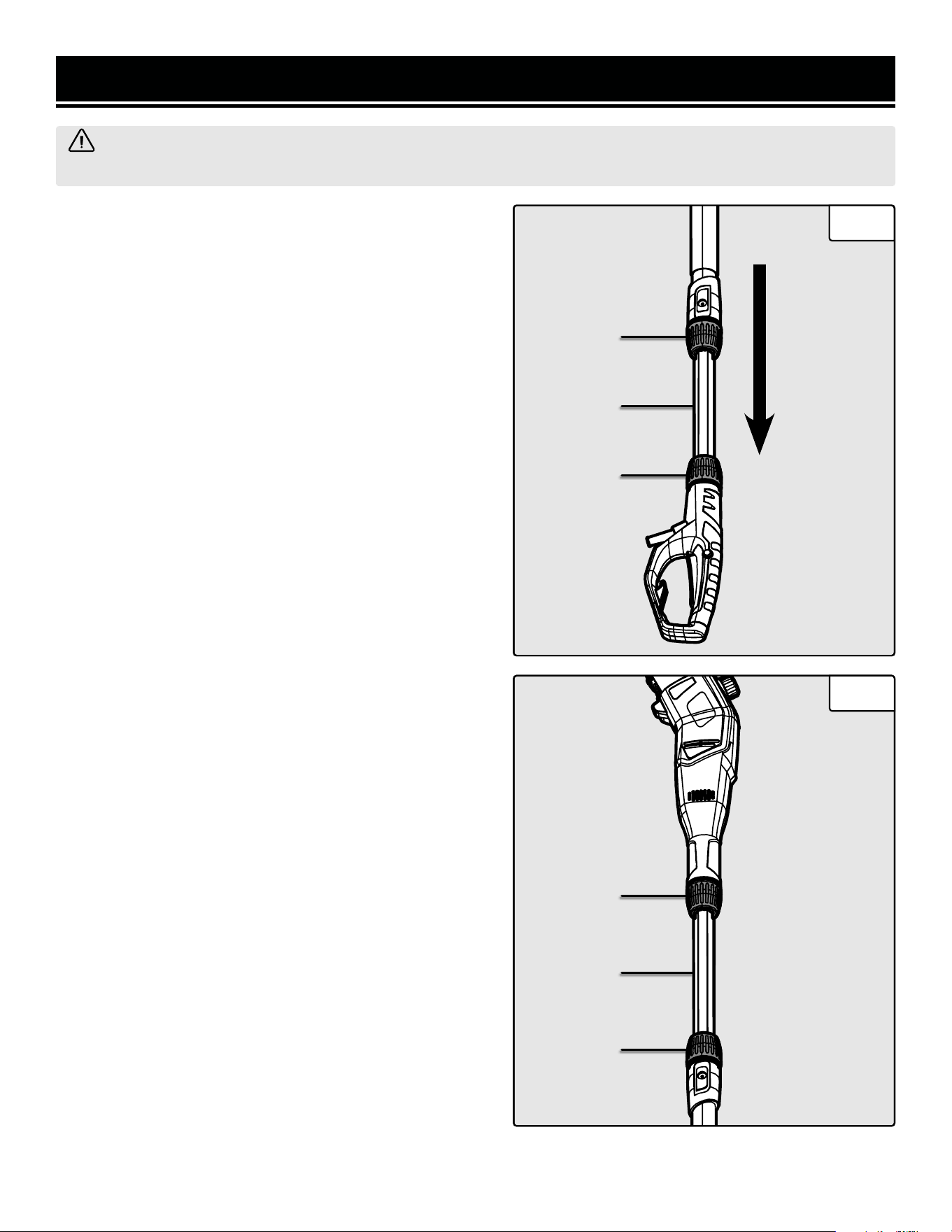
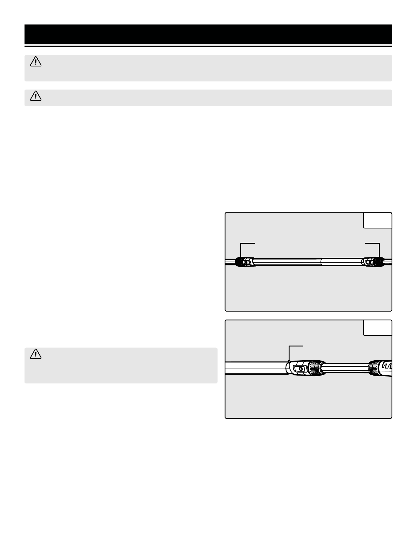
ASSEMBLING THE POLE SAW HANDLE & SHAFT
1. Loosen the shaft coupling (Fig. 1 - 1) on the pole saw shaft
by turning it counterclockwise. Extend the shaft (Fig. 1 - 2)
to the desired length and lock it in place by turning the shaft
coupling clockwise.
NOTE: The extension pole should be pulled out at least 2
inches to properly install the handle.
2. Loosen the coupling (Fig. 1 - 3) on the pole saw handle by
turning it counterclockwise.
3. Align the locking pin on the shaft extension pole with the
locking hole on the handle. Slide the extension pole into the
handle until they lock together. You should hear a slight click
and see the pin pop into place.
4. Lock the shaft in place by turning the handle coupling (Fig.
1 - 3) clockwise.
ASSEMBLING THE POLE SAW HEAD & SHAFT
1. Loosen the shaft coupling (Fig. 2 - 1) on the pole saw shaft
by turning it counterclockwise. Extend the shaft (Fig. 2 - 2)
to the desired length and lock it in place by turning the shaft
coupling clockwise.
NOTE: The extension pole should be pulled out at least 2
inches to properly install the saw head.
2. Loosen the coupling (Fig. 2 - 3) on the pole saw head by
turning it counterclockwise.
3. Align the locking pin on the shaft extension pole with the
locking hole on the head. Slide the extension pole into the
saw head until they lock together. You should hear a slight
click and see the pin pop into place.
4. Lock the shaft in place by turning the head coupling (Fig.
2 - 3) clockwise.
ASSEMBLY & ADJUSTMENTS
Fig. 1
Fig. 2
1
3
2
3
2
1
12
WARNING! To avoid injury from accidental startups, be sure that the tool is switched OFF and removed from
the power source before inspecting the unit, making adjustments, or changing accessories.
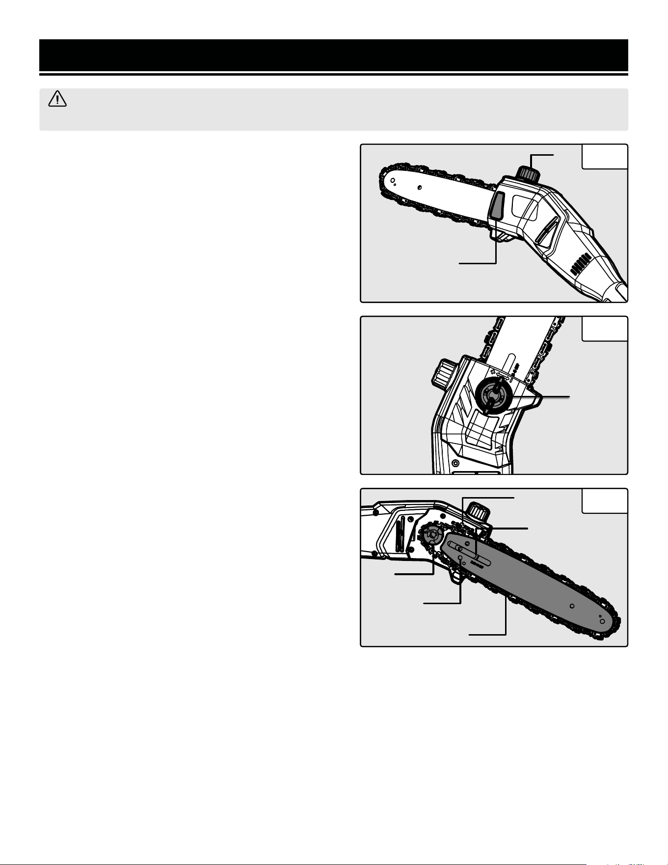
FILLING THE AUTO-OILING SYSTEM
This pole saw features an auto-oiling system to keep the
chain and guide bar properly lubricated. The oil level window
(Fig. 3 - 1) shows the remaining oil in the pole saw. If the oil
level decreases to below one quarter capacity, refill it with
the proper bar and chain oil.
To fill the oil tank:
1. Place the saw on a level surface. Clean the area around the
oil tank cap (Fig. 3 - 2) to avoid getting dirt into the oil tank.
Once clean, remove the oil tank cap.
2. Fill the oil tank with saw chain oil. Make sure that no dirt
gets into the oil tank to avoid clogging the oil nozzle. Replace
the oil tank cap. Make sure that the cover is secure before
beginning operation.
ASSEMBLING THE GUIDE BAR & SAW CHAIN
1. Place the saw's body on a firm and level surface.
2. Turn the cover release knob (Fig. 4 - 1) counterclockwise
to remove the cover from the saw’s body.
3. While wearing protective gloves, wrap the saw chain
around the guide bar (Fig. 5 - 1), making sure that the teeth
are aimed in the direction of rotation (Fig. 5 - 2). The chain
should be properly set in the slot running along the entire
outside edge of the guide bar.
4. Place the saw chain around the sprocket (Fig. 5 - 3) and
guide bar (Fig.5 - 4), ensuring the chain's drive links fit se-
curely into the guide bar's groove.
5. While holding the bar still, place the cover back onto the
saw. Tighten the cover release knob until it is snug but not
fully tightened, allowing for tension adjustment before final
tightening. Ensure that the tensioning pin on the back of the
cover sits inside the tensioning hole (Fig. 5 - 5). Fully tighten
the cover release knob.
ASSEMBLY & ADJUSTMENTS
Fig. 3
Fig. 4
Fig. 5
2
1
1
1
2
3
4
5
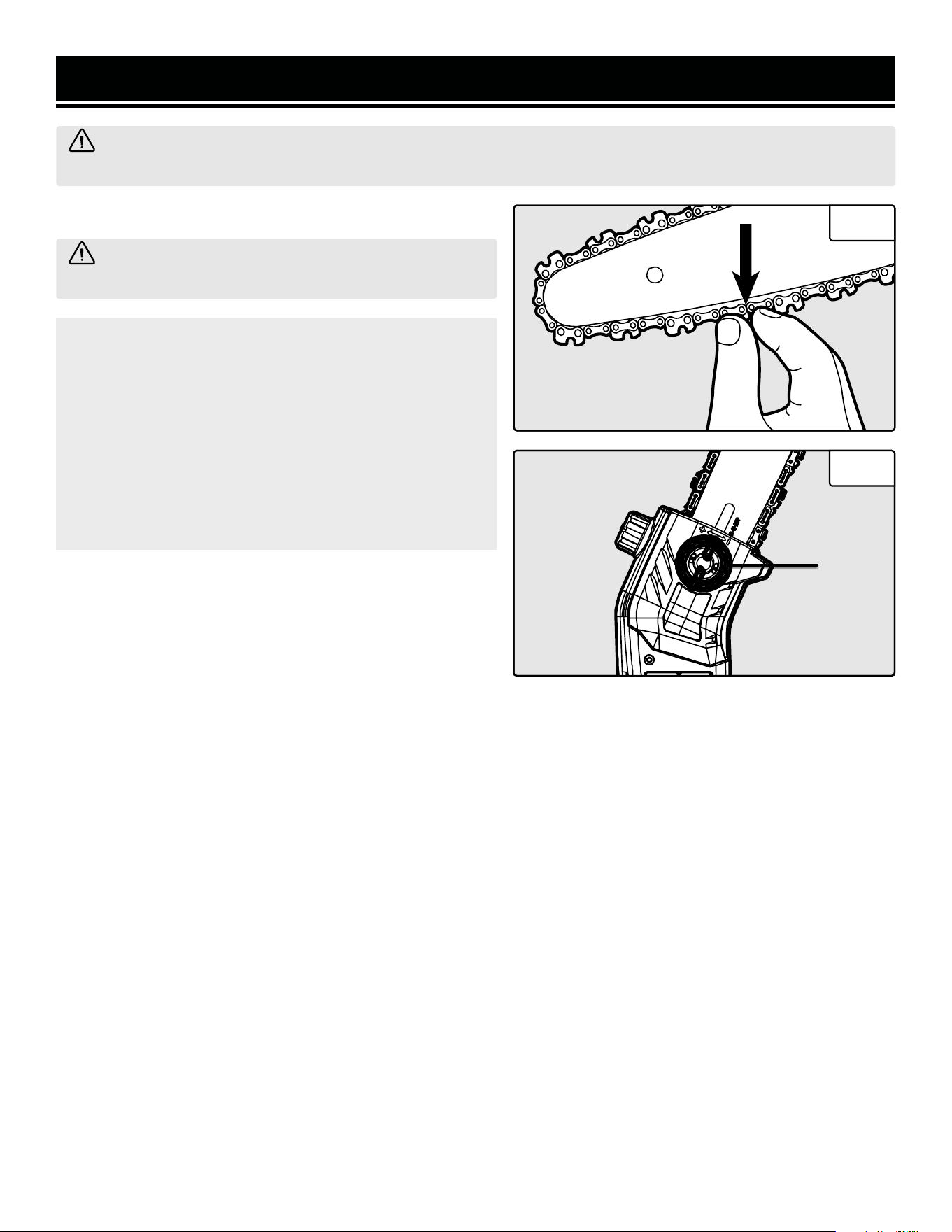
NOTE: The saw chain must be tensioned properly in order
to ensure safe operation. The chain tension is optimal if
the saw chain can be lifted 1/8 inch (3mm) from the cen-
ter of the guide bar. Since the saw chain heats up during
operation, its length can therefore fluctuate. Check the
chain tension every 10 minutes of operation and adjust
as necessary, particularly for new saw chains. Slacken
the saw chain after the work is completed since it short-
ens when cooling down. In doing so, you can elongate
the chain’s life and prevent damage.
1. Check the chain tension by pulling the saw chain away
from the guide bar. A properly tensioned chain should have
roughly 1/8 inch (3 mm) of distance between itself and the
bar guide (Fig. 6).
2. To adjust the saw chain tension, loosen the guide bar by
slightly turning the cover release knob counterclockwise.
3. Set the tension of the saw chain using the chain tensioning
ring (Fig. 7 - 1). Turn the chain tensioning ring counterclock-
wise to increase the tension and clockwise to decrease the
tension.
4. Once the chain has been properly tensioned, tighten the
cover release knob.
1/8"
(3mm)
WARNING! When handling saw chains, always wear
protective gloves to prevent injury.
13
WARNING! To avoid injury from accidental startups, be sure that the tool is switched OFF and removed from
the power source before inspecting the unit, making adjustments, or changing accessories.
TENSIONING THE CHAIN
ASSEMBLY & ADJUSTMENTS
Fig. 6
Fig. 7
1
14
ADJUSTING THE LENGTH OF THE POLE SAW
1. Unlock the shaft couplings (Fig. 8 - 1) to adjust the length
of the extension poles by turning them counterclockwise.
2. To lock the extension poles in place, turn the shaft cou-
plings clockwise. Make sure that the couplings are securely
tightened before beginning operation.
USING THE SHOULDER STRAP
1. Hook the shoulder strap onto the shoulder strap hook (Fig.
9 - 1). The shoulder strap helps to support the weight of the
saw during transportation and operation. Only put the shoul-
der strap onto one shoulder so that you can move rapidly
away from the tool in case of danger.
WARNING! To avoid injury from accidental startups, be sure that the tool is switched OFF and removed from
the power source before inspecting the unit, making adjustments, or changing accessories.
ASSEMBLY & ADJUSTMENTS
Fig. 6
Fig. 7
WARNING! When handling saw chains, always wear protective gloves to prevent injury.
SAW CHAIN LUBRICATION
Make sure that the pole saw is powered OFF and removed from the power source before making any adjustment.
Never operate the pole saw without saw chain oil. The use of the pole saw without enough saw chain oil will damage
the unit.
Only use dedicated bar and chain oil designed for chainsaws and pole saws. Other oils will run the risk of damaging
the unit and voiding the warranty.
Take note of temperature conditions. Using the saw at various temperatures requires the use of differing oils. To
ensure a sufficient layer of lubricant at lower temperatures, use lower-viscosity oil.
WARNING! Never wear the strap diagonally across
your shoulders, as you won’t be able to quickly move
away from the tool.
1 1
1

OPERATION
15
PREPARING FOR OPERATION
Before each use, check the following items to ensure safe working conditions.
POLE SAW: Before beginning work, inspect the pole saw for damage to the housing, the saw chain, and the guide
bar. Never use an obviously damaged machine.
CHAIN OIL: Check the fill level of the oil tank. Also check whether there is sufficient oil available while working. Never
operate the saw if there is no oil or the oil level has dropped below the minimum oil level mark in order to prevent
damage to the pole saw. On average, an oil filling is sufficient for approximately 10 minutes of cutting operation
(depending on the duration of pauses and the density of the workpiece).
SAW CHAIN: Check the tension of the saw and the condition of the blades. The sharper the saw chain is, the easier
and more manageable operations will be. The same applies for the chain tension. Check the tension every 10 min-
utes of operation to maximize safety. New saw chains in particular are subject to changes due to the heat created by
operation. Never allow the saw chain to contact dirt or soil.
PROTECTIVE CLOTHING: Make absolutely sure to wear the appropriate close-fitting protective clothing, such as
protective pants, gloves and safety shoes. Wear a safety helmet with integrated hearing protection and a face guard
to provide protection against falling and recoiling branches.
SAFETY WARNINGS
1. In order to ensure safe work, do not operate the saw at an angle of over 60 degrees.
2. Never stand below a branch that is being sawed.
3. Exercise caution when sawing branches under tension or branches that are splintering.
4. Make sure to safeguard against the risk of injury from falling branches and flying wood projectiles.
5. If the machine is operating, keep people and animals away from the area.
6. The machine is not protected against electric shock when coming into contact with high-voltage lines. Maintain a
minimum clearance of 30 feet from current-carrying power lines to avoid life-threatening electric shock.
7. When working on an incline, always stand above or to the side of the branch being sawed.
8. Allow the chain to cut for you. Keep the saw running at full speed for the entire duration of the cut.
PREVENTING KICKBACK
The term kickback refers to when the saw suddenly jumps up and back. This is usually caused by the workpiece
coming into contact with the guide bar tip or the clamping of the saw chain.
A kickback generates an abrupt powerful force. The saw usually reacts in an uncontrolled manner, creating the pos-
sibility of injury to the user.
The danger of a kickback is greatest when attempting to cut near or with the guide bar tip. Always apply the saw as
flatly as possible in order to avoid a loss of control during operation.
16
Cut 1
(1/3 Diameter)
Cut 2
(2/3 Diameter)
Cut 3
(Finishing Cut)
WARNING! Do not cut down trees in high wind conditions. This can result in injury and should only be per-
formed by a trained professional.
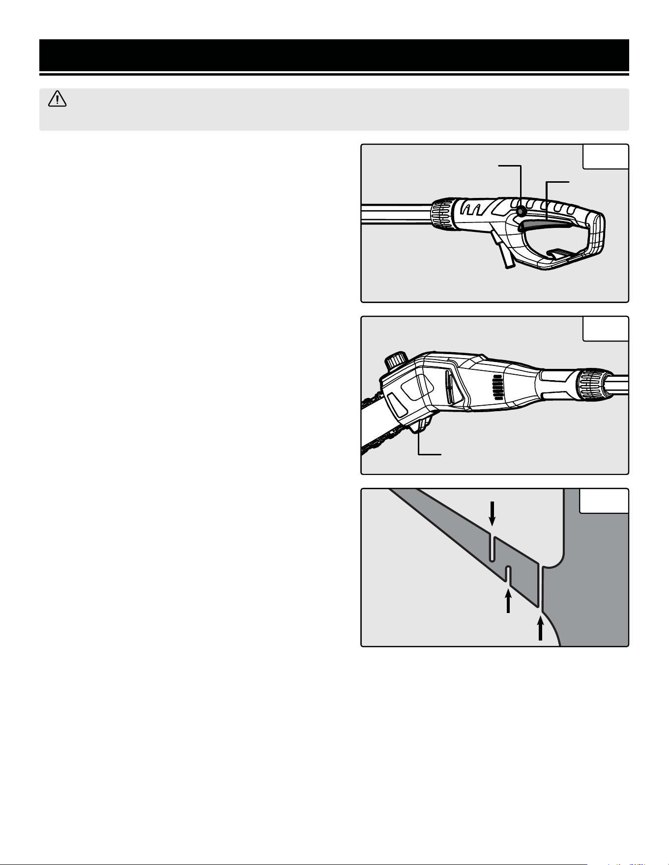
POWERING THE POLE SAW ON / OFF
1. Plug the pole saw into the power source.
To turn the tool ON: Press the trigger lock (Fig. 8 - 1) while
simultaneously pulling the power trigger (Fig. 8 - 2) to start
the pole saw.
To turn the tool OFF: Release the power trigger to stop the
pole saw. Once operation has been completed, unplug the
pole saw from the power source.
SAWING TECHNIQUES
When removing branches, hold the pole saw at an angle
ranging from 0 to 60° in order to avoid being struck by a fall-
ing branch. The saw should never be operated directly above
anyone’s head.
Saw off the lower branches on the tree first. By doing so, it is
easier for the cut branches to fall to the ground.
At the end of the cut, the weight of the saw suddenly in-
creases for the user since it is no longer being supported by
a branch. There is a risk of losing control of the saw, so make
sure to stay alert during the entire sawing operation.
Only pull the saw out of a cut while the saw is running. By
doing so, you prevent the chain from jamming in the wood.
Do not saw with the tip of the guide bar. Do not saw into the
branch formations (where the tree branches outwards). This
will impede the tree’s ability to heal.
For sawing off smaller branches, place the stop face (Fig. 9
- 1) of the saw on the branch. This prevents unwanted move-
ments of the saw at the beginning of the cut. While applying
light pressure, guide the saw through the branch from top
to bottom.
For sawing off larger branches, first make a relief cut. Saw
through 1/3 of the branch diameter from the bottom to top
using the top side of the guide bar. Then saw from top to
bottom for the other 2/3 using the bottom side of the guide
bar. Saw off longer branches in sections in order to maintain
control over the location of impact (Fig. 10).
OPERATION
Fig. 8
Fig. 9
Fig. 10
2
1
1

MAINTENANCE
ROUTINE INSPECTION
Before each use, inspect the general condition of the tool.
If any of these following conditions exist, do not use until
parts are replaced or the sharpener is properly repaired.
Check for:
• Loose hardware or improper mounting
• Misalignment or binding of moving parts
• Damaged power cord
• Cracked or broken parts
• Any other condition that may affect its safe operation
CLEANING & STORAGE
1. Brush or blow dust and debris out of the air vents us-
ing compressed air or a vacuum. Keep the air vents free
of obstructions, sawdust, and wood chips. Do not spray,
wash, or immerse the air vents in water.
2. Wipe off the housing and the plastic components us-
ing a moist, soft cloth. Do not use strong solvents or
detergents on the plastic housing or plastic components.
Certain household cleaners may cause damage, and may
cause a shock hazard.
3. Routinely clean out the dust and debris that gathers
under the tension housing, the oil outlet, and around the
bar and the chain sprocket. Otherwise it can jam up the
sprocket, the chain, and the lubrication system.
4. If the pole saw is not used for an extended period of
time, drain the chain oil from the tank. Briefly place the
chain and the guide bar in an oil bath and then wrap in
oil paper to dry.
WARNING! Any attempt to repair or replace electrical parts on this tool may be hazardous. Servicing of the
tool must be performed by a qualified technician. When servicing, use only identical WEN replacement parts.
Use of other parts may be hazardous or induce product failure.
17
LUBRICATION
All bearings and gears are sealed and permanently lubri-
cated. No further lubrication is required.
AUTOMATIC CHAIN LUBRICATION
Regularly check the functionality of the automatic chain
lubrication in order to prevent overheating and the sub-
sequent damage to the guide bar and saw chain asso-
ciated with it. For this purpose, align the guide bar tip
against a smooth surface (board, cut-in of a tree) and
allow the pole saw to run. If an increasing amount of
oil appears, the automatic chain lubrication functions
properly.
PRODUCT DISPOSAL
Used power tools should not be disposed of together
with household waste. This product contains electronic
components that should be recycled. Please take this
product to your local recycling facility for responsible
disposal and to minimize its environmental impact.
WARNING! To avoid injury from accidental startups, be sure that the tool is switched OFF and removed from
the power source before cleaning, adjusting, or performing any maintenance or lubrication work.
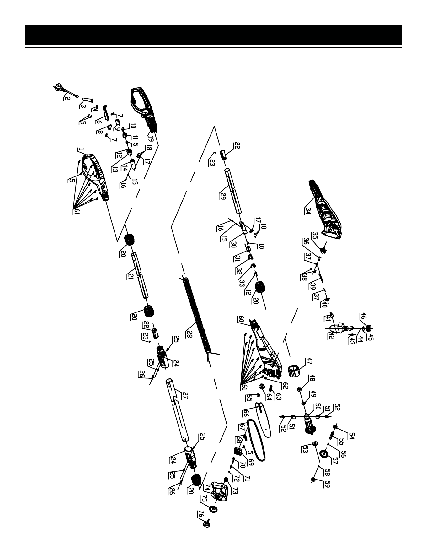
EXPLODED VIEW & PARTS LIST
NOTE: Not all parts may be available for purchase. Parts and accessories that wear
down over the course of normal use are not covered under the warranty.
18

EXPLODED VIEW & PARTS LIST
NO. PART NO. DESCRIPTION QTY.
1 CP0810-001 Right Handle 1
2 CP0810-002 Power Cord 1
3 CP0810-003 Cable Sheath 1
4 CP0810-004 Crimp Plate 1
5 CP0810-005 Self-Tapping Screws 5
6 CP0810-006 Switch Button 1
7 CP0810-007
Anti-Self-Locking
Push Button Spring
2
8 CP0810-008
Anti-Self-Locking
Push Button
1
9 CP0810-009 Switch 1
10 CP0810-010 Female Terminal 4
11 CP0810-011 Female Terminal Block A 1
12 CP0810-012 Male Terminal 4
13 CP0810-013 Male Terminal Cover 1
14 CP0810-014 Male Terminal Block A 1
15 CP0810-015 Self-Locking Spring 2
16 CP0810-016 Self-Locking Pin 2
17 CP0810-017 Self-Locking Spring 2
18 CP0810-018 Self Tapping Screws 4
19 CP0810-019 Left Handle 1
20 CP0810-020 Locking Sleeve 4
21 CP0810-021 Lower Shaft 1
22 CP0810-022 Limiting Tube 2
23 CP0810-023 Positioning Post 2
24 CP0810-024 Connecting Sleeve 2
25 CP0810-025 Machine Screws 4
26 CP0810-026 Machine Screws 2
27 CP0810-027 Glass Fiber Shaft 1
28 CP0810-028 Spring Wire 1
29 CP0810-029 Extending Shaft 1
30 CP0810-030
Female Terminal Block Lower
Cover
1
31 CP0810-031 Female Terminal Block B 1
32 CP0810-032
Female Terminal Block Upper
Cover
1
33 CP0810-033 Male Terminal Block B 1
34 CP0810-034 Left Housing 1
35 CP0810-035 Oil Pump Assembly 1
36 CP0810-036 Oil Inlet Pipe 1
37 CP0810-037 Oil Pipe Spring 2
38 CP0810-038 Flange Self-Tapping Screws 2
39 CP0810-039 Oil Outlet Pipe 1
NO. PART NO. DESCRIPTION QTY.
40 CP0810-040 Fuel Tank Seal 1
41 CP0810-041
Fuel Tank Connector
Assembly
1
42 CP0810-042 Fuel Tank 1
43 CP0810-043 Valve 1
44 CP0810-044 Anti Loss Hook 1
45 CP0810-045 Fuel Cap Seal 1
46 CP0810-046 Fuel Tank Cover 1
47 CP0810-047 Stator 1
48 CP0810-048 Bearing Bush 1
49 CP0810-049
Deep Groove Ball
Bearings
1
50 CP0810-050 Rotor 1
51 CP0810-051 Carbon brush Holder 2
52 CP0810-052 Carbon Brush 2
53 CP0810-053
Deep Groove Ball
Bearings
1
54 CP0810-054
Deep Groove Ball
Bearings
1
55 CP0810-055 Output Shaft 1
56 CP0810-056 Semicircular Key 1
57 CP0810-057 Large Gear 1
58 CP0810-058 Shaft Sleeve 1
59 CP0810-059
Deep Groove Ball
Bearings
1
60 CP0810-060 Right Housing 1
61 CP0810-061 Self-Tapping Screws 22
62 CP0810-062 Tension Spring 1
63 CP0810-063 Ring Seal 1
64 CP0810-064 Sprocket 1
65 CP0810-065 E-Ring 1
66 CP0810-066 Guide Plate 1
67 CP0810-067 Chain 1
68 CP0810-068 End Cap Seal 1
69 CP0810-069 End cap Cover 1
70 CP0810-070 Adjusting Pinion 1
71 CP0810-071 Tension Nut 1
72 CP0810-072 Wire Retainer 1
73 CP0810-073 Tensioning Tooth Adjuster 1
74 CP0810-074 Toolless End Caps 1
75 CP0810-075 Adjustment Knob 1
76 CP0810-076 Compression Knob 1
19

20
EXPLODED VIEW & PARTS LISTWARRANTY STATEMENT
WEN Products is committed to building tools that are dependable for years. Our warranties are consistent with this
commitment and our dedication to quality.
LIMITED WARRANTY OF WEN PRODUCTS FOR HOME USE
GREAT LAKES TECHNOLOGIES, LLC (“Seller”) warrants to the original purchaser only, that all WEN consumer power
tools will be free from defects in material or workmanship during personal use for a period of two (2) years from date
of purchase or 500 hours of use; whichever comes first. Ninety days for all WEN products if the tool is used for pro-
fessional or commercial use. Purchaser has 30 days from the date of purchase to report missing or damaged parts.
SELLER’S SOLE OBLIGATION AND YOUR EXCLUSIVE REMEDY under this Limited Warranty and, to the extent per-
mitted by law, any warranty or condition implied by law, shall be the replacement of parts, without charge, which are
defective in material or workmanship and which have not been subjected to misuse, alteration, careless handling,
misrepair, abuse, neglect, normal wear and tear, improper maintenance, or other conditions adversely affecting the
Product or the component of the Product, whether by accident or intentionally, by persons other than Seller. To make
a claim under this Limited Warranty, you must make sure to keep a copy of your proof of purchase that clearly defines
the Date of Purchase (month and year) and the Place of Purchase. Place of Purchase must be a direct vendor of Great
Lakes Technologies, LLC. Purchasing through third party vendors, including but not limited to garage sales, pawn
shops, resale shops, or any other secondhand merchant, voids the warranty included with this product. Contact tech-
[email protected] or 1-847-429-9263 with the following information to make arrangements: your shipping
address, phone number, serial number, required part numbers, and proof of purchase. Damaged or defective parts and
products may need to be sent to WEN before the replacements can be shipped out.
Upon the confirmation of a WEN representative, your product may qualify for repairs and service work. When returning
a product for warranty service, the shipping charges must be prepaid by the purchaser. The product must be shipped
in its original container (or an equivalent), properly packed to withstand the hazards of shipment. The product must be
fully insured with a copy of the proof of purchase enclosed. There must also be a description of the problem in order
to help our repairs department diagnose and fix the issue. Repairs will be made and the product will be returned and
shipped back to the purchaser at no charge for addresses within the contiguous United States.
THIS LIMITED WARRANTY DOES NOT APPLY TO ITEMS THAT WEAR OUT FROM REGULAR USAGE OVER TIME, IN-
CLUDING BELTS, BRUSHES, BLADES, BATTERIES, ETC. ANY IMPLIED WARRANTIES SHALL BE LIMITED IN DURA-
TION TO TWO (2) YEARS FROM DATE OF PURCHASE. SOME STATES IN THE U.S. AND SOME CANADIAN PROVINCES
DO NOT ALLOW LIMITATIONS ON HOW LONG AN IMPLIED WARRANTY LASTS, SO THE ABOVE LIMITATION MAY
NOT APPLY TO YOU.
IN NO EVENT SHALL SELLER BE LIABLE FOR ANY INCIDENTAL OR CONSEQUENTIAL DAMAGES (INCLUDING BUT
NOT LIMITED TO LIABILITY FOR LOSS OF PROFITS) ARISING FROM THE SALE OR USE OF THIS PRODUCT. SOME
STATES IN THE U.S. AND SOME CANADIAN PROVINCES DO NOT ALLOW THE EXCLUSION OR LIMITATION OF IN-
CIDENTAL OR CONSEQUENTIAL DAMAGES, SO THE ABOVE LIMITATION OR EXCLUSION MAY NOT APPLY TO YOU.
THIS LIMITED WARRANTY GIVES YOU SPECIFIC LEGAL RIGHTS, AND YOU MAY ALSO HAVE OTHER RIGHTS WHICH
VARY FROM STATE TO STATE IN THE U.S., PROVINCE TO PROVINCE IN CANADA AND FROM COUNTRY TO COUN-
TRY.
THIS LIMITED WARRANTY APPLIES ONLY TO ITEMS SOLD WITHIN THE UNITED STATES OF AMERICA, CANADA
AND THE COMMONWEALTH OF PUERTO RICO. FOR WARRANTY COVERAGE WITHIN OTHER COUNTRIES, CONTACT
THE WEN CUSTOMER SUPPORT LINE. FOR WARRANTY PARTS OR PRODUCTS REPAIRED UNDER WARRANTY
SHIPPING TO ADDRESSES OUTSIDE OF THE CONTIGUOUS UNITED STATES, ADDITIONAL SHIPPING CHARGES MAY
APPLY.
V. 2025.02.13