
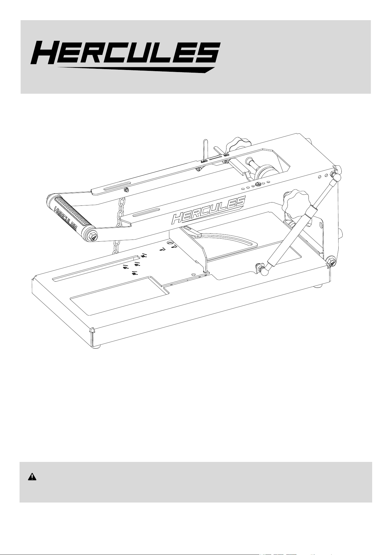
Model
HH78S
Universal Portable Band Saw
Benchtop Stand
WARNING: To prevent serious injury, User must read and understand
Owner’s Manual. SAVE THIS MANUAL.
When unpacking, make sure that the product is intact and undamaged.
If any parts are missing or broken, please call 1-800-444-3353
as soon as possible. Reference 59640.
TM
Owner’s Manual &
Safety Instructions
25c

Page 2 For technical questions, please call 1-800-444-3353. Item 59640
IMPORTANT SAFETY INFORMATION
Read all safety warnings and all instructions.
Failure to follow the warnings and instructions may result
in electric shock, fire and/or serious injury. Save all
warnings and instructions for future reference.
1. PRIOR TO USING THIS PRODUCT, READ
AND UNDERSTAND ALL INSTRUCTIONS
AND SAFETY PRECAUTIONS AS OUTLINED
IN THE MANUFACTURER’S MANUAL OF
THE BAND SAW THAT IS TO BE USED.
2. MAKE SURE THE BAND SAW STAND IS
PLACED ON A FLAT, LEVEL, HARD SURFACE
CAPABLE OF SUPPORTING THE WEIGHT
OF THE BAND SAW STAND, BAND SAW
BEING USED, AND WORKPIECE.
3. BOLT THE BAND SAW STAND SECURELY
TO THE WORK BENCH AND TEST WORK
SET-UP FOR STABILITY BEFORE USE.
4. KEEP ALL GUARDS IN PLACE
AND IN WORKING ORDER.
5. MAKE SURE THE WORKPIECE IS SUPPORTED
AT ALL TIMES DURING OPERATION.
6. UNPLUG THE BAND SAW FROM ITS ELECTRICAL
SUPPLY SOURCE BEFORE PERFORMING ANY
SERVICE OR MAINTENANCE ON THE BAND SAW
STAND. Make sure to unplug the Band saw before
leaving the work area, moving the Band saw Stand
from one location to another, cleaning the Stand, etc.
7. Wear ANSI-approved safety goggles
during assembly and use.
8. Do not exceed listed weight capacity. Be aware
of dynamic loading! Sudden load movement may
briefly create excess load causing product failure.
9. Weight capacity and other product capabilities apply
to properly and completely assembled product only.
10. When folding or unfolding the Band saw
Stand, be careful not to pinch fingers.
11. This product is not a toy.
Do not allow children to play with or near this item.
12. Use as intended only.
13. Keep hands clear of moving parts.
14. Maintain labels and nameplates on the tool.
These carry important safety information.
If unreadable or missing, contact
Harbor Freight Tools for a replacement.
15. Stay alert, watch what you are doing and use
common sense when operating a power tool. Do
not use a power tool while you are tired or under
the influence of drugs, alcohol or medication. A
moment of inattention while operating power
tools may result in serious personal injury.
16. The warnings, precautions, and instructions
discussed in this instruction manual cannot
cover all possible conditions and situations
that may occur. It must be understood by the
operator that common sense and caution are
factors which cannot be built into this product,
but must be supplied by the operator.
Vibration Safety
This tool vibrates during use. Repeated or long-term
exposure to vibration may cause temporary or permanent
physical injury, particularly to the hands, arms and
shoulders. To reduce the risk of vibration-related injury:
1. Anyone using vibrating tools regularly or for an
extended period should first be examined by a
doctor and then have regular medical check-ups
to ensure medical problems are not being caused
or worsened from use. Pregnant women or
people who have impaired blood circulation to
the hand, past hand injuries, nervous system
disorders, diabetes, or Raynaud’s Disease should
not use this tool. If you feel any medical or
physical symptoms related to vibration (such as
tingling, numbness, and white or blue fingers),
seek medical advice as soon as possible.
2. Do not smoke during use. Nicotine reduces
the blood supply to the hands and fingers,
increasing the risk of vibration-related injury.
3. Use tools with the lowest vibration when there
is a choice between different processes.
4. Include vibration-free periods each day of work.
5. Grip workpiece as lightly as possible (while still
keeping safe control of it). Let the tool do the work.
6. To reduce vibration, maintain the tool as
explained in this manual. If any abnormal
vibration occurs, stop use immediately.
SAVE THESE INSTRUCTIONS.

Page 3For technical questions, please call 1-800-444-3353.Item 59640
Warning Symbols and Definitions
This is the safety alert symbol. It is used to
alert you to potential personal injury hazards.
Obey all safety messages that follow this symbol to
avoid possible injury or death.
Indicates a hazardous
situation which, if not
avoided, will result in death or serious injury.
Indicates a hazardous
situation which, if not
avoided, could result in death or serious injury.
Indicates a hazardous
situation which, if not
avoided, could result in minor or moderate injury.
Addresses practices not
related to personal injury.
Specifications
Compatibility
Hercules, Bauer, Milwaukee,
and Dewalt Portable
Deep Cut Band Saws
Cutting Capacity
Refer to Band Saw manufacturer’s
instruction manual
TM
Page 4 For technical questions, please call 1-800-444-3353. Item 59640
SETUP - BEFORE USE
Read the ENTIRE IMPORTANT SAFETY INFORMATION section at the beginning of this manual
including all text under
subheadings therein before set up or use
.
TO PREVENT SERIOUS INJURY FROM ACCIDENTAL OPERATION: Release the Trigger and remove the
battery pack or unplug tool before performing any procedure in this section.
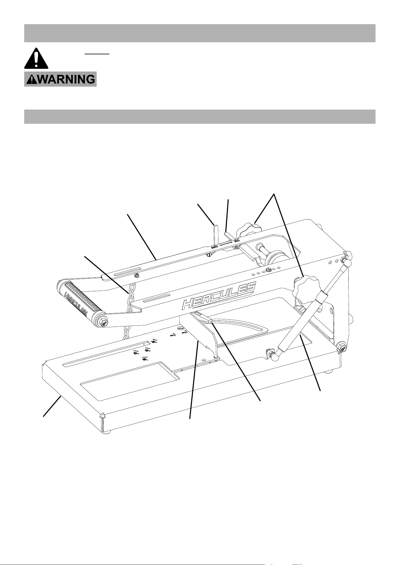
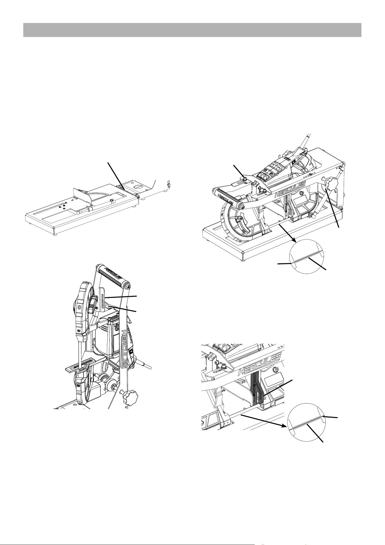
Functional Description
Chain
Trigger
Lever
Trigger
Switch
Adjustment
Knobs
Gas
Strut
Fence
Arm
Base
Miter Angle
Knob
Page 5For technical questions, please call 1-800-444-3353.Item 59640
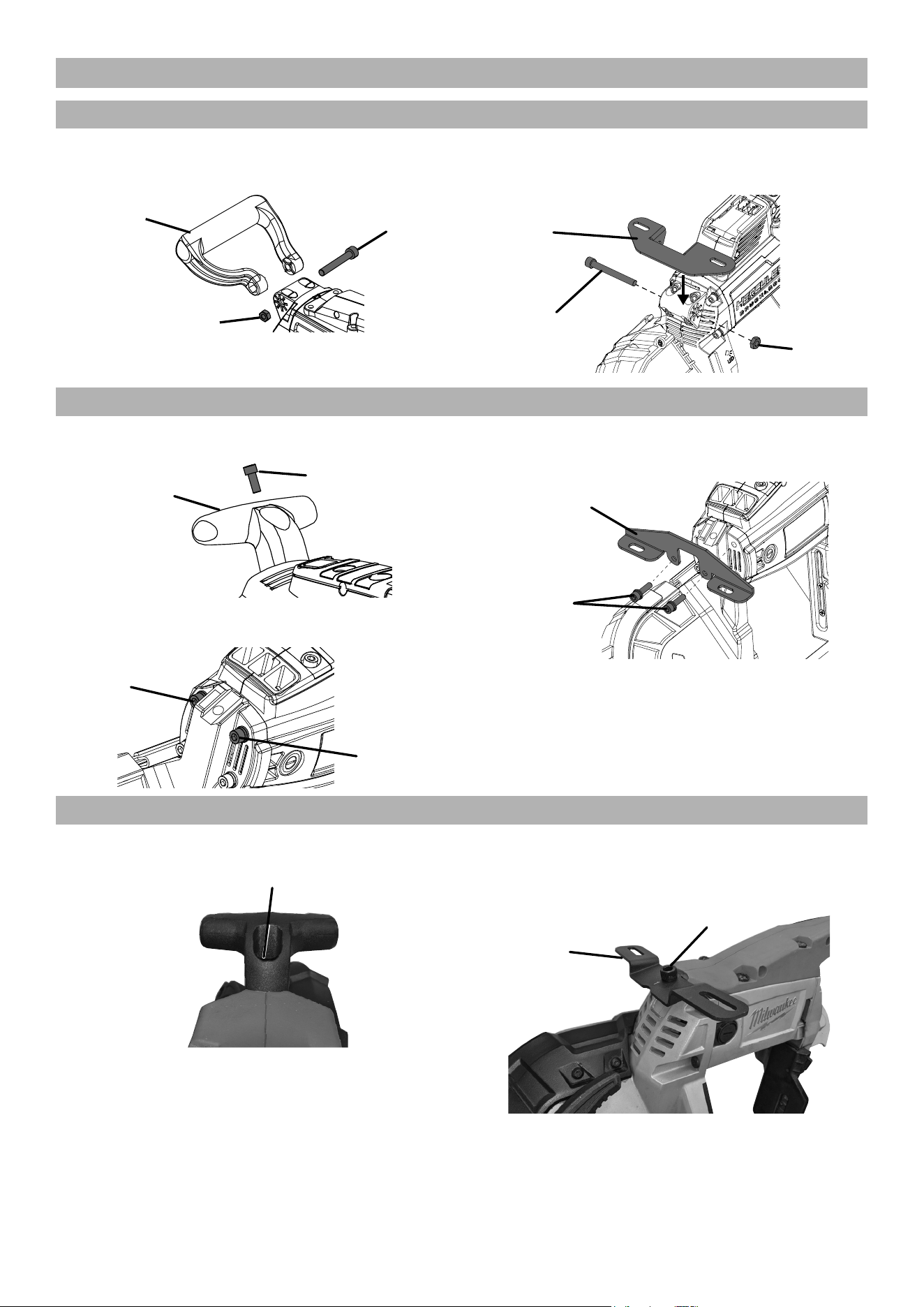
Attaching Bracket to Band Saw
Hercules Corded and Cordless
1. Remove Nut and Bolt from Handle,
then remove Handle.
Handle
Bolt
Nut
2. Attach Bracket (32) using Bolt and
Nut from Handle, finger tighten.
Bracket
(32)
Handle
Bolt
Handle
Nut
Bauer Corded and Cordless
1. Remove Bolt from Handle, then remove Handle.
Handle
Bolt
2. Remove upper Bolts from housing.
Upper
Bolt
Upper
Bolt
3. Attach Bracket (33), using
housing Bolts, finger tighten.
Housing
Bolts
Bracket
(33)
Milwaukee Corded and Cordless
1. Remove Bolt from Handle, then remove Handle.
Bolt
2. Attach Bracket (34), using Bolt
from Handle, finger tighten.
Bracket
(34)
Handle
Bolt
Page 6 For technical questions, please call 1-800-444-3353. Item 59640
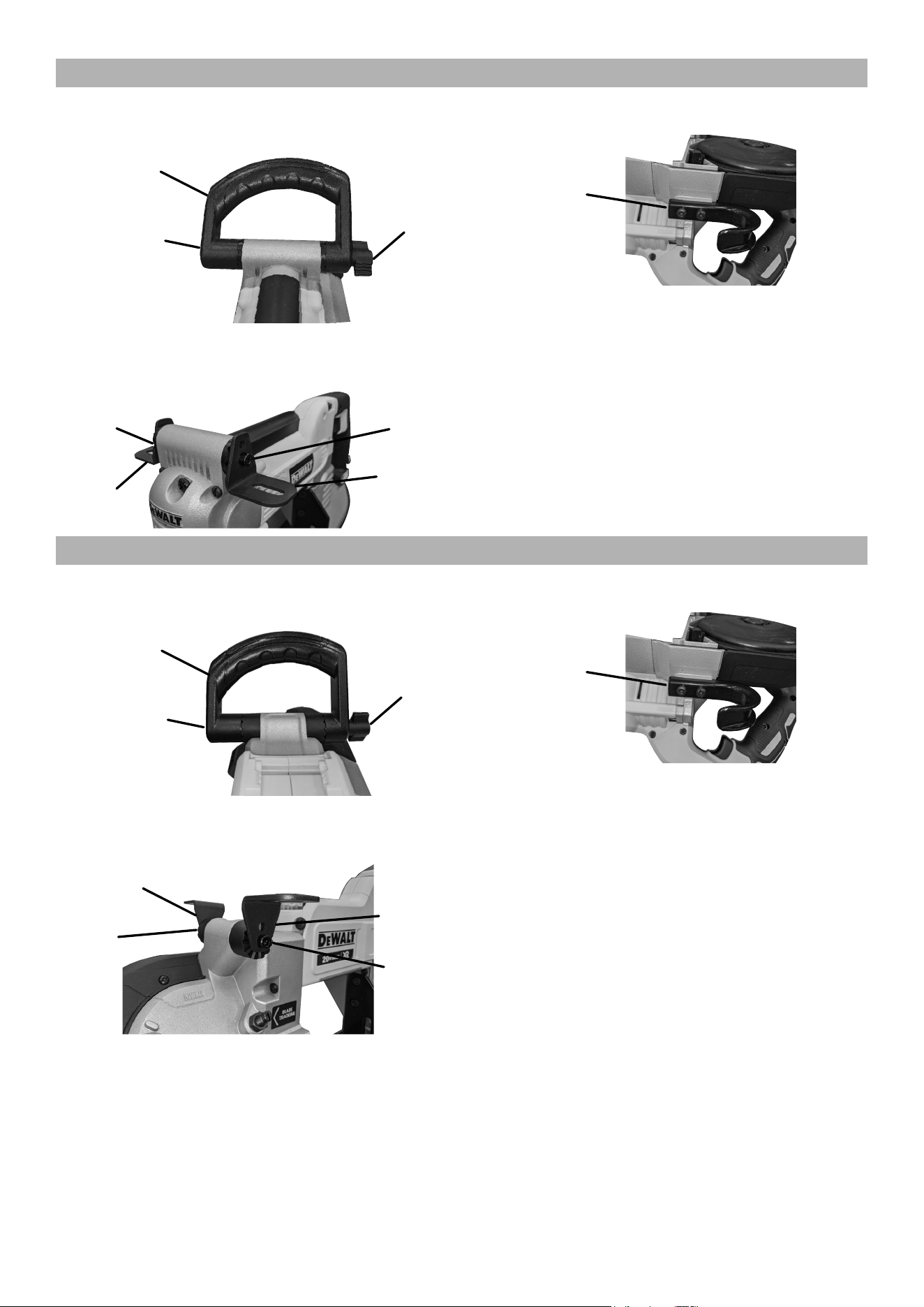
Dewalt Corded
1. Remove Nut, Bolt and Washer from
Handle, then remove Handle.
Handle
Bolt and
Washer
Nut
2. Attach Brackets (35) to lower holes using
Bolt and Nut (40), finger tighten.
Bracket
(35)
Bracket
(35)
Bolt in
Lower
Hole
Nut in
Lower
Hole
3. Remove Hook.
Hook
Dewalt Cordless
1. Remove Nut, Bolt and Washer from
Handle, then remove Handle.
Handle
Bolt and
Washer
Nut
2. Attach Brackets (35) to lower holes using
Bolt and Nut (41), finger tighten.
Nut in
Lower
Hole
Bracket
(35)
Bracket
(35)
Bolt in
Lower
Hole
3. Remove Hook.
Hook
Page 7For technical questions, please call 1-800-444-3353.Item 59640
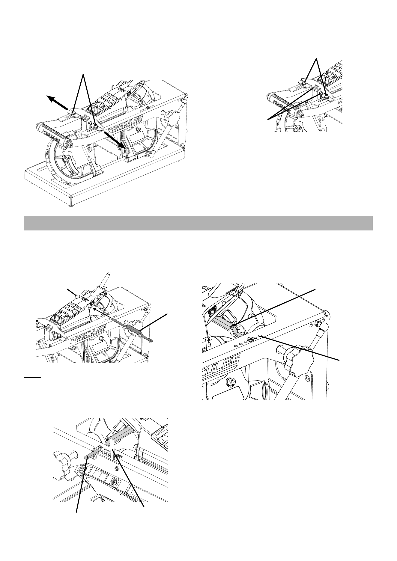
Attaching Band Saw To Stand
WARNING! TO PREVENT SERIOUS INJURY: Band saw blade is sharp.
Wear heavy-duty work gloves while attaching band saw.
1. Remove Chain from Arm.
2. Using quick release, remove Gas Strut from Arm.
3. Lift Arm to upright position.
4. Loosen Adjustment Knobs.
5. Check level between Base and Arm. If necessary,
loosen three Bolts between Base and Arm,
level Stand, then tighten Bolts securely.
Adjustment
Bolts
6. Slide band saw up and into Stand with
Brackets on outside of Bracket Support.
Bracket
Bracket
Support
7. Route power cord through Power Cord Hole.
8. Lower Arm slowly, adjusting band saw so
that blade fits inside Blade Channel.
9. Attach Gas Strut and Chain.
10. Attach Brackets with Bolts, Spring Washers,
Flat Washers and Nuts (42), finger tighten.
0
°
30
°
0
°
45
°
45
°
60
°
Blade
Channel
Blade
Bolt, Washer,
Spring Washer,
Nut (42)
Power
Cord Hole
11. Move band saw forward until Guide Bar
is as close as possible to edge of Stand
without touching edge when lifting Arm.
12. Tighten Adjustment Knobs securely. Band
saw should be parallel to Arm of stand. Blade
should be parallel to Blade Channel.
30
°
Blade
Blade Channel
Guide
Bar
13. If Blade is not centered in the Blade Channel,
adjust back of band saw by loosening or tightening
Adjustment Knobs until Blade is centered in Channel.
Page 8 For technical questions, please call 1-800-444-3353. Item 59640
14. If Blade is not centered in the Blade Channel,
loosen the Bolts (42) holding the Bracket
in place. Move the band saw to either side
until blade is centered in Channel. Finger
tighten Bolts after making adjustments.
Bolts (42)
15. Securely tighten hardware on Bracket to Stand, then
securely tighten hardware on Bracket to band saw.
Bracket to Stand
Hardware
Bracket to
band saw
Hardware
Installing Trigger Lever
1. Make sure band saw trigger is in OFF position.
Disconnect power from band saw.
2. Slide Trigger Lever through band saw opening.
Trigger
Switch
Trigger
Lever
Note: Trigger Lever may need to be flipped upside
down to make proper contact with band saw’s trigger.
3. Push the end of the Trigger Lever without a hole
through the slot shared with Trigger Switch. Trigger
Lever should sit beneath the ON marking.
Trigger Arm
Trigger
Switch
4. Push Trigger Lever until band saw trigger is
fully depressed. Slide the end of the Trigger
Lever with the hole to the nearest threaded
hole on Stand. Secure Lever in corresponding
hole using Bolt (9) and Washer (23).
Threaded
Holes
Trigger
Lever
5. Move Trigger Switch of OFF position. Trigger
Lever should move to the OFF position.
Page 9For technical questions, please call 1-800-444-3353.Item 59640
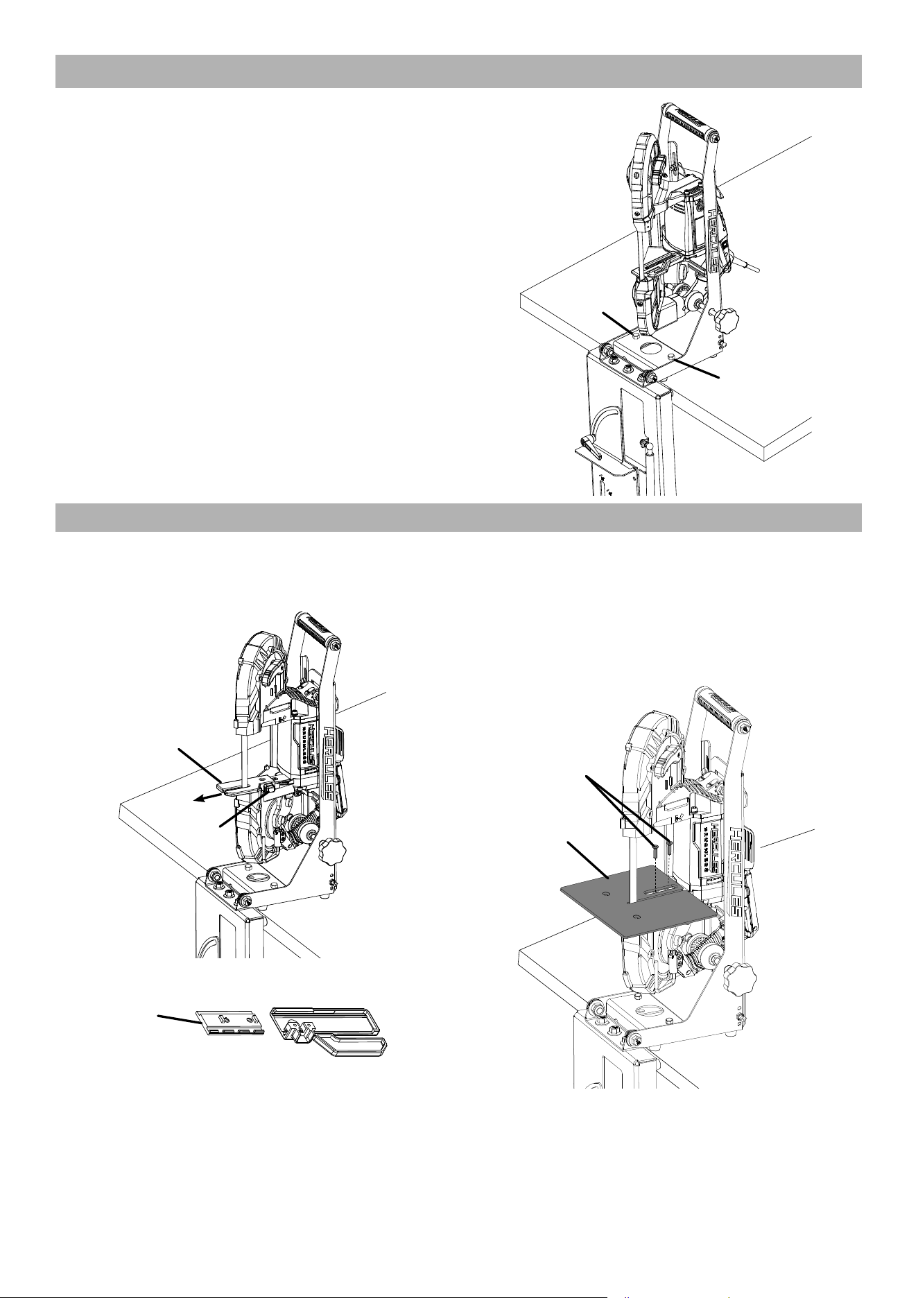
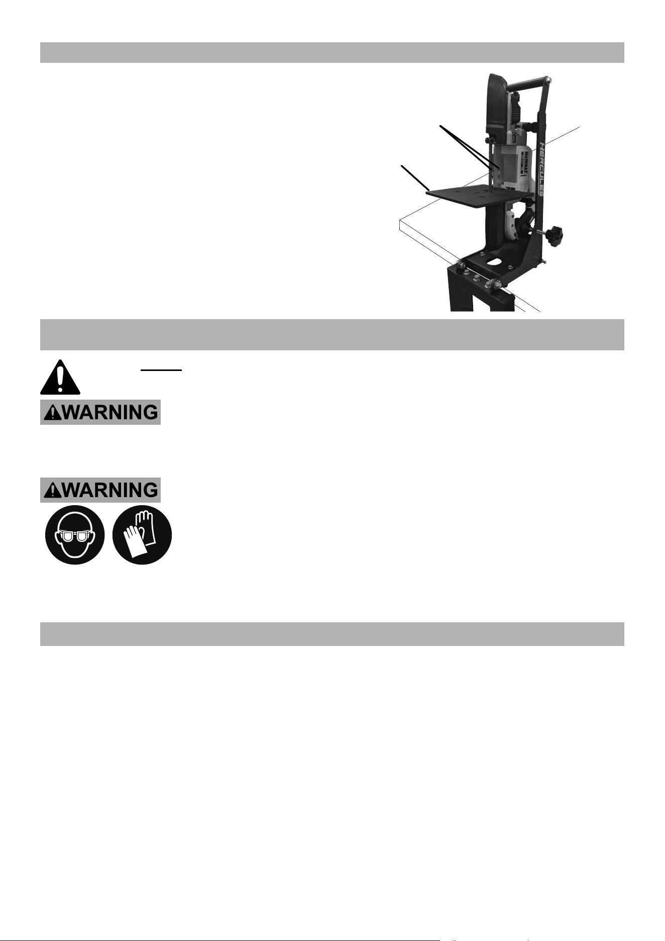
Vertical Setup
1. Remove Chain from Arm.
2. Using quick release, remove Gas Strut from Arm.
3. Lift Arm to vertical position.
4. Move Stand to edge of surface
with Base hanging down.
5. Mounting: Using appropriate hardware, mount
stand to flat, level, hard surface capable of
supporting the weight of the band saw stand,
band saw, and workpiece. TEST WORK
SET UP FOR STABILITY BEFORE USE.
Mounting
Hole
Mounting
Hole
Hercules Corded and Cordless
1. Press Button, then pull Guide Bar out to expose Bolts.
2. Remove Bolts and Guide Bar.
Guide
Bar
Button
3. Slide Plate out of Guide bar, then replace Plate.
Plate
4. Install Table over Plate, positioning it as far out
as possible to create maximum work space.
5. Adjust Table so that Blade is
centered in Blade Channel.
6. Secure Table using Bolts (44), tighten securely.
Bolts
(44)
Table
Page 10 For technical questions, please call 1-800-444-3353. Item 59640
Bauer Corded
1. Remove Bolts and Guide Bar.
2. Install Table where Guide Bar was, positioning it as
far out as possible to create maximum work space.
3. Adjust Table so that Blade is
centered in Blade Channel.
4. Secure Table using Bolts from
Guide Bar, tighten securely.
Table
Guide
Bar
Bolts
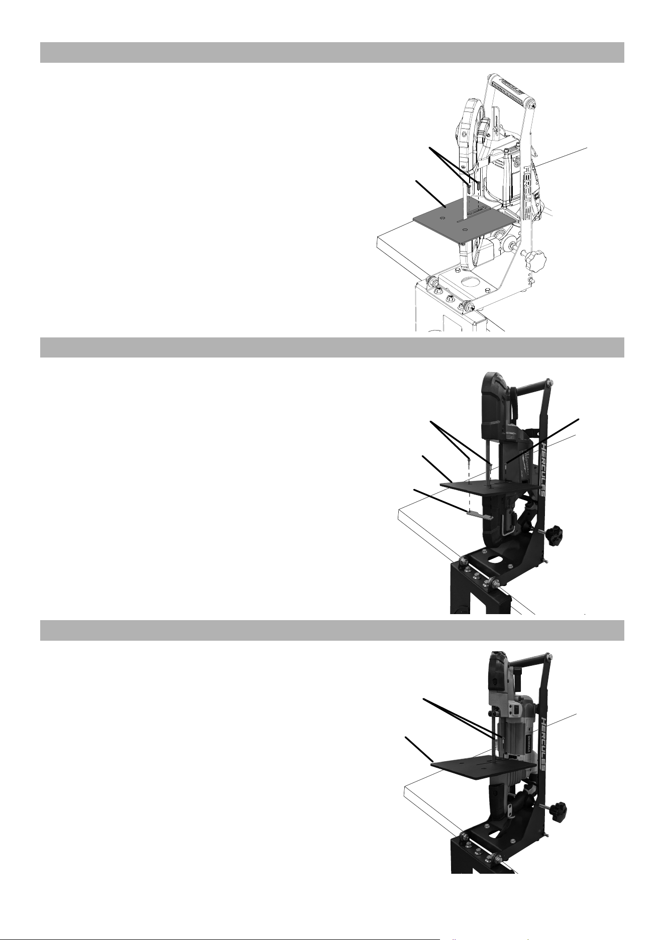
Milwaukee Corded and Cordless
1. Pull Guide Bar out to expose Bolt.
2. Remove Bolt.
3. Install Table, positioning it as far out as
possible to create maximum work space.
4. Adjust Table so that Blade is
centered in Blade Channel.
5. Secure Table using Bolt (43), tighten securely.
6. Secure Table Bracket using
Bolts(44), tighten securely.
Table
Bracket
Bolts
(44)
Table
Bolt
(43)
Dewalt Corded
1. Remove Bolts and Guide Bar.
2. Install Table where Guide Bar was, positioning it as
far out as possible to create maximum work space.
3. Adjust Table so that Blade is
centered in Blade Channel.
4. Secure Table using Bolts from
Guide Bar, tighten securely.
Guide
Bar
Bolts
Table
Page 11For technical questions, please call 1-800-444-3353.Item 59640
Dewalt Cordless
1. Remove Bolts and Guide Bar.
2. Install Table where Guide Bar was, positioning it as
far out as possible to create maximum work space.
3. Adjust Table so that Blade is
centered in Blade Channel.
4. Secure Table using Bolts from
Guide Bar, tighten securely.
Table
Guide
Bar
Bolts
OPERATING INSTRUCTIONS
Read the ENTIRE IMPORTANT SAFETY INFORMATION section at the beginning of this manual
including all text under
subheadings therein before set up or use
.
TO PREVENT SERIOUS INJURY FROM ACCIDENTAL OPERATION:
Make sure that the Trigger is in the off-position and unplug the tool or remove
its Battery Pack before performing any procedure in this section.
TO PREVENT SERIOUS INJURY: Wear ANSI-approved safety goggles, heavy-duty
work gloves, and heavy-duty long-sleeved shirt or coat whenever working near the
Blade. Do not wear gloves when sawing.
READ AND FOLLOW THE BAND SAW MANUFACTURER’S INSTRUCTION MANUAL
BEFORE OPERATION. USE AS BAND SAW STAND ONLY – DO NOT USE WITH ANY OTHER
TYPE OF POWER TOOL. DO NOT USE ON UNEVEN OR SLIPPERY SURFACES.
Workpiece and Work Area Set Up
1. Designate a work area that is clean and well-lit.
The work area must not allow access by children
or pets to prevent distraction and injury.
2. Route the power cord along a safe route to reach
the work area without creating a tripping hazard or
exposing the power cord to possible damage. The
power cord must reach the work area with enough
extra length to allow free movement while working.
3. Secure loose workpieces using clamps
(sold separately) to prevent movement while working.
4. There must not be objects, such as utility lines,
nearby that will present a hazard while working.
Page 12 For technical questions, please call 1-800-444-3353. Item 59640
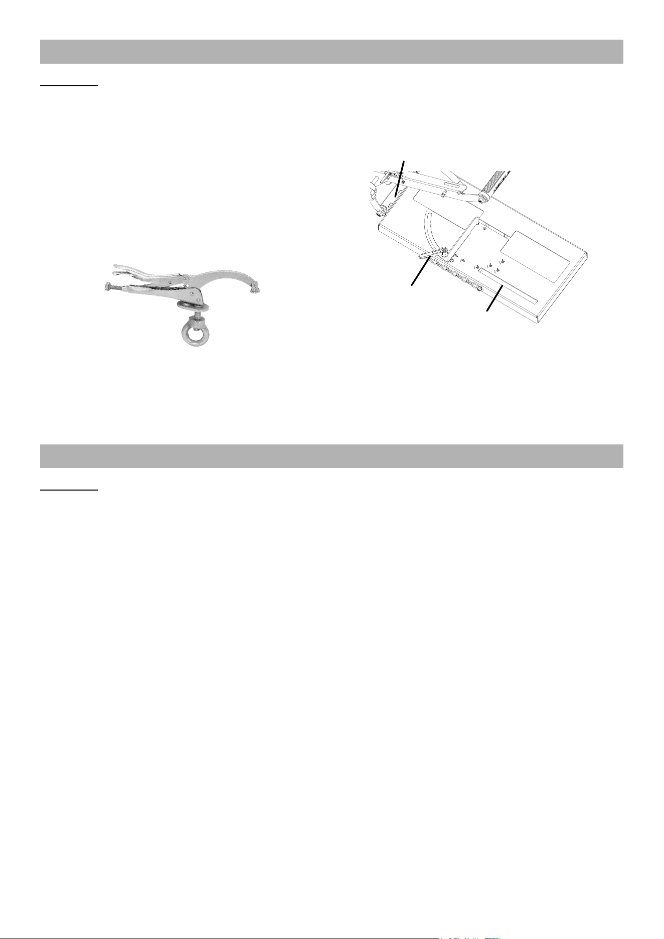
Horizontal Operation
WARNING! TO PREVENT SERIOUS INJURY: READ AND FOLLOW THE BAND SAW MANUFACTURER’S
INSTRUCTION MANUAL BEFORE OPERATION. DO NOT WEAR GLOVES WHEN SAWING.
1. Set up Band Saw according to its instruction manual.
2. Install Band Saw into Stand, then plug into
grounded 120VAC outlet or install battery pack.
3. Make test cut:
a. Using 3″ diameter thick-wall steel pipe or
square tube, draw a line along length of pipe.
b. Using Harbor Freight 9″ Drill Press Clamp,
slide Clamp’s ring into Clamp Slot and
secure pipe with the line facing up.
c. With Band Saw in upright position, move
Trigger Switch to On position, make straight
cut, then use T-Square to check cut on
line and at 90° from line on both sides.
d. If necessary, fine tune adjustment with
three Bolts between Base and Arm.
4. Set angle: Loosen Miter Angle Knob,
set angle then tighten Knob.
Miter
Angle
Knob
Adjustment
Bolts
Clamp
Slot
5. With Band Saw in upright position, move Trigger
Switch to On position. After cut is finished,
move Trigger Switch to OFF position.
6. To prevent accidents, disconnect tool’s
power supply after use. Clean, then store
the tool indoors out of children’s reach.
Vertical Operation
WARNING! TO PREVENT SERIOUS INJURY: READ AND FOLLOW THE BAND SAW MANUFACTURER’S
INSTRUCTION MANUAL BEFORE OPERATION. DO NOT WEAR GLOVES WHEN SAWING.
1. Set up Band Saw according to its instruction manual.
2. Install Band Saw in Stand, then plug into
grounded 120VAC outlet or install battery pack.
3. Types of Cuts:
a. Standard cuts are at 90° angle to the Table,
use both hands to guide material, keeping
the workpiece flat against the Table.
b. Make Contour cuts by guiding the workpiece
free-handed for curve shapes, use both
hands to guide material, keeping the
workpiece flat against the Table.
4. Mark material to be cut.
5. Move Trigger Switch to On position, then
make cut. After cut is finished, move
Trigger Switch to OFF position.
6. To prevent accidents, disconnect tool’s
power supply after use. Clean, then store
the tool indoors out of children’s reach.

Page 13For technical questions, please call 1-800-444-3353.Item 59640
MAINTENANCE
Procedures not specifically explained in this manual must
be performed only by a qualified technician.
TO PREVENT SERIOUS INJURY FROM ACCIDENTAL OPERATION: Release the Trigger and unplug tool or
remove the Battery Pack before performing any procedure in this section.
TO PREVENT SERIOUS INJURY FROM TOOL FAILURE:
Do not use damaged equipment. If abnormal noise or vibration
occurs, have the problem corrected before further use.
1. BEFORE EACH USE, inspect the general
condition of the tool. Check for:
• loose hardware,
• misalignment or binding of moving parts,
• cracked or broken parts,
• any other condition that may
affect its safe operation.
2. AFTER USE, wipe external surfaces of
the tool with clean cloth, then store the
tool indoors out of children’s reach.

Page 14 For technical questions, please call 1-800-444-3353. Item 59640
PLEASE READ THE FOLLOWING CAREFULLY
THE MANUFACTURER AND/OR DISTRIBUTOR HAS PROVIDED THE PARTS LIST AND ASSEMBLY DIAGRAM
IN THIS MANUAL AS A REFERENCE TOOL ONLY. NEITHER THE MANUFACTURER OR DISTRIBUTOR
MAKES ANY REPRESENTATION OR WARRANTY OF ANY KIND TO THE BUYER THAT HE OR SHE IS
QUALIFIED TO MAKE ANY REPAIRS TO THE PRODUCT, OR THAT HE OR SHE IS QUALIFIED TO REPLACE
ANY PARTS OF THE PRODUCT. IN FACT, THE MANUFACTURER AND/OR DISTRIBUTOR EXPRESSLY
STATES THAT ALL REPAIRS AND PARTS REPLACEMENTS SHOULD BE UNDERTAKEN BY CERTIFIED AND
LICENSED TECHNICIANS, AND NOT BY THE BUYER. THE BUYER ASSUMES ALL RISK AND LIABILITY
ARISING OUT OF HIS OR HER REPAIRS TO THE ORIGINAL PRODUCT OR REPLACEMENT PARTS
THERETO, OR ARISING OUT OF HIS OR HER INSTALLATION OF REPLACEMENT PARTS THERETO.
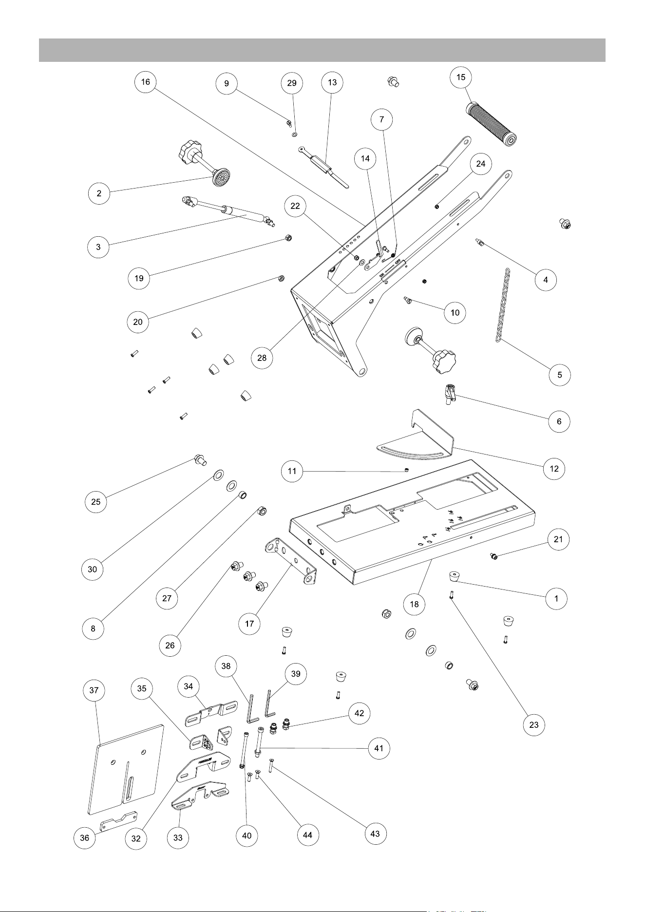
PARTS LIST AND DIAGRAM
Parts List
Part Description Qty
1 Foot 8
2 Knob 2
3 Gas Strut 1
4 Chain Bolt 1
5 Chain 1
6 Angle Lever 1
7 Spring 1
8 Sleeve 2
9 Trigger Lever Bolt 2
10 Trigger Switch Bolt 1
11 Sleeve 1
12 Angle Plate 1
13 Trigger Lever 1
14 Trigger Switch 1
15 Handle 1
16 Upper Arm 1
17 Adjustable Plate 1
18 Base 1
19 M8 Lock Nut 1
20 M8 Nut 4
21 M6X12 Hex Bolt 1
22 M6 Lock Nut 2
23 M5X16 Bolt 8
Part Description Qty
24 M5 Lock Nut 2
25 M12X20 Hex Flange Bolt 2
26 M12X16 Hex Flange Bolt 5
27 M12 Lock Nut 2
28 8X16X1.5 Washer 1
29 6X12X1 Washer 1
30 30X17X1.5 Washer 4
32 Hercules Bracket 1
33 Bauer Bracket 1
34 Milwaukee Bracket 1
35 Dewalt Bracket 2
36 Milwaukee Table Bracket 1
37 Table 1
38 6mm Hex Wrench 1
39 5mm Hex Wrench 1
40 Dewalt Bracket M6X95 GB70
Hex Bolt, Nut
1
41 Hercules Bracket M8X75-GB70
Hex Bolt, Nut
1
42 Bracket to Stand M8X20 Stand Bolt,
Spring Washer, Flat Washer, Nut
2
43 Milwaukee Table M5X35 Bolt 1
44 Table Bracket M6X20 Bolt 2
Record Product’s Serial Number Here:
Note: If product has no serial number, record month and year of purchase instead.
Note: Replacement parts may be available for this item.
Visit harborfreight.com/parts for a list of in stock parts. Reference UPC 193175477316.
Page 15For technical questions, please call 1-800-444-3353.Item 59640
Assembly Diagram

TM
26677 Agoura Road • Calabasas, CA 91302 • 1-800-444-3353
Visit our website at: https://www.harborfreight.com
Email our technical support at: [email protected]
For technical questions, please call 1-800-444-3353
Copyright
©
2025 by Harbor Freight Tools
®
. All rights reserved. No portion of this manual or
any artwork contained herein may be reproduced in any shape or form without the express
written consent of Harbor Freight Tools. Diagrams within this manual may not be drawn
proportionally. Due to continuing improvements, actual product may differ slightly from the
product described herein. Tools required for assembly and service may not be included.
LIMITED 90 DAY WARRANTY
Harbor Freight Tools Co. makes every effort to assure that its products meet high quality and durability standards,
and warrants to the original purchaser that this product is free from defects in materials and workmanship for the
period of 90 days from the date of purchase. This warranty does not apply to damage due directly or indirectly,
to misuse, abuse, negligence or accidents, repairs or alterations outside our facilities, criminal activity, improper
installation, normal wear and tear, or to lack of maintenance. We shall in no event be liable for death, injuries
to persons or property, or for incidental, contingent, special or consequential damages arising from the use of
our product. Some states do not allow the exclusion or limitation of incidental or consequential damages, so the
above limitation of exclusion may not apply to you. THIS WARRANTY IS EXPRESSLY IN LIEU OF ALL OTHER
WARRANTIES, EXPRESS OR IMPLIED, INCLUDING THE WARRANTIES OF MERCHANTABILITY AND FITNESS.
To take advantage of this warranty, the product or part must be returned to us with transportation charges
prepaid. Proof of purchase date and an explanation of the complaint must accompany the merchandise.
If our inspection verifies the defect, we will either repair or replace the product at our election or we may
elect to refund the purchase price if we cannot readily and quickly provide you with a replacement. We will
return repaired products at our expense, but if we determine there is no defect, or that the defect resulted
from causes not within the scope of our warranty, then you must bear the cost of returning the product.
This warranty gives you specific legal rights and you may also have other rights which vary from state to state.
HERCULES and BAUER are trademarks of Harbor Freight Tools.
All other marks are trademarks of their respective owners.