
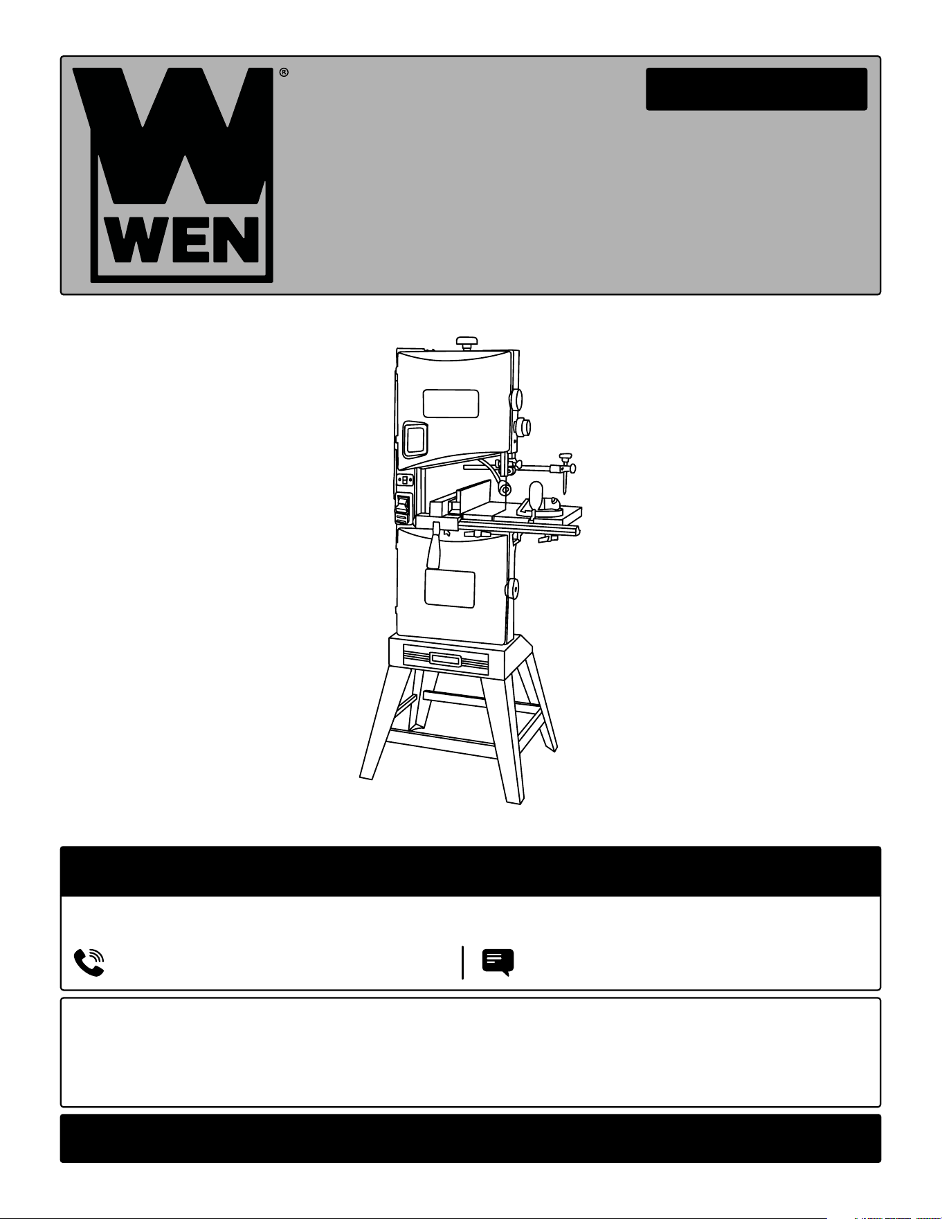
14-INCH TWO-SPEED
BAND SAW WITH STAND
Instruction Manual
IMPORTANT: Your new tool has been engineered and manufactured to WEN’s highest standards for dependability,
ease of operation, and operator safety. When properly cared for, this product will supply you years of rugged,
trouble-free performance. Pay close attention to the rules for safe operation, warnings, and cautions. If you use
your tool properly and for its intended purpose, you will enjoy years of safe, reliable service.
NEED HELP? CONTACT US!
Have product questions? Need technical support? Please feel free to contact us:
TECHSUPPOR[email protected]1-847-429-9263 (M-F 8AM-5PM CST)
For replacement parts and the most up-to-date instruction manuals, visit WENPRODUCTS.COM
MODEL BA1487

2
CONTENTS
WELCOME 3
Introduction ......................................................................................................3
Specifications ................................................................................................... 3
SAFETY 4
General Safety Rules ........................................................................................ 4
Specific Rules for Your Band Saw .................................................................... 6
Electrical Information ....................................................................................... 8
9
Unpacking & Packing List ................................................................................ 9
Know Your Band Saw ..................................................................................... 10
Assembly & Adjustments ............................................................................... 11
BEFORE OPERATING
OPERATION & MAINTENANCE 17
Operation ....................................................................................................... 17
Maintenance ....................................................................................................20
Exploded View & Parts List ............................................................................ 21
Warranty Statement ....................................................................................... 26
To purchase accessories for your tool, visit WENPRODUCTS.COM
Woodcutting Bandsaw Blade (Models BB9912, BB9925, BB9950)

INTRODUCTION
Thanks for purchasing the WEN Band Saw. We know you are excited to put your tool to work, but first, please
take a moment to read through the manual. Safe operation of this tool requires that you read and understand this
operator’s manual and all the labels affixed to the tool. This manual provides information regarding potential safety
concerns, as well as helpful assembly and operating instructions for your tool.
NOTE: The following safety information is not meant to cover all possible conditions and situations that may occur.
WEN reserves the right to change this product and specifications at any time without prior notice.
At WEN, we are continuously improving our products. If you find that your tool does not exactly match this manual,
please visit wenproducts.com for the most up-to-date manual or contact our customer service at 1-847-429-9263.
Keep this manual available to all users during the entire life of the tool and review it frequently to maximize
safety for both yourself and others.
SPECIFICATIONS
Model Number BA1487
Motor 120V, 60 Hz, 9.5A
Throat 13-3/8 Inches
Cutting Depth 8.85 Inches
Blade Speed 1480 / 3280 FPM
Table Angle 0º to 45º
Work Table Dimensions 18.90 in. x 15.35 in.
Blade Length 100-3/4 Inches
Blade Width 1/8 to 1 Inch
Product Weight 130.95 Pounds
Product Dimensions 21 in. x 31 in. x 67 in.
3
SAFETY ALERT SYMBOL: Indicates danger, warning, or caution. The safety symbols and the explanations
with them deserve your careful attention and understanding. Always follow the safety precautions to reduce the
risk of fire, electric shock or personal injury. However, please note that these instructions and warnings are not
substitutes for proper accident prevention measures.

GENERAL SAFETY RULES
4
WORK AREA SAFETY
1. Keep work area clean and well lit. Cluttered or dark
areas invite accidents.
2. Do not operate power tools in explosive atmo-
spheres, such as in the presence of flammable liq-
uids, gases or dust. Power tools create sparks which
may ignite the dust or fumes.
3. Keep children and bystanders away while operat-
ing a power tool. Distractions can cause you to lose
control.
ELECTRICAL SAFETY
1. Power tool plugs must match the outlet. Never
modify the plug in any way. Do not use any adapter
plugs with earthed (grounded) power tools. Unmodi-
fied plugs and matching outlets will reduce risk of elec-
tric shock.
2. Avoid body contact with earthed or grounded sur-
faces such as pipes, radiators, ranges and refrigera-
tors. There is an increased risk of electric shock if your
body is earthed or grounded.
3. Do not expose power tools to rain or wet condi-
tions. Water entering a power tool will increase the risk
of electric shock.
4. Do not abuse the cord. Never use the cord for car-
rying, pulling or unplugging the power tool. Keep cord
away from heat, oil, sharp edges or moving parts.
Damaged or entangled cords increase the risk of elec-
tric shock.
5. When operating a power tool outdoors, use an ex-
tension cord suitable for outdoor use. Use of a cord
suitable for outdoor use reduces the risk of electric
shock.
6. If operating a power tool in a damp location is
unavoidable, use a ground fault circuit interrupter
(GFCI) protected supply. Use of a GFCI reduces the risk
of electric shock.
PERSONAL SAFETY
1. Stay alert, watch what you are doing and use com-
mon sense when operating a power tool. Do not use a
power tool while you are tired or under the influence
of drugs, alcohol or medication. A moment of inatten-
tion while operating power tools may result in serious
personal injury.
2. Use personal protective equipment. Always wear
eye protection. Protective equipment such as a respi-
ratory mask, non-skid safety shoes and hearing protec-
tion used for appropriate conditions will reduce the risk
of personal injury.
3. Prevent unintentional starting. Ensure the switch is
in the off-position before connecting to power source
and/or battery pack, picking up or carrying the tool.
Carrying power tools with your finger on the switch or
energizing power tools that have the switch on invites
accidents.
4. Remove any adjusting key or wrench before turning
the power tool on. A wrench or a key left attached to a
rotating part of the power tool may result in personal
injury.
5. Do not overreach. Keep proper footing and balance
at all times. This enables better control of the power
tool in unexpected situations.
6. Dress properly. Do not wear loose clothing or jew-
elry. Keep your hair and clothing away from moving
parts. Loose clothes, jewelry or long hair can be caught
in moving parts.
Safety is a combination of common sense, staying alert and knowing how your item works. The term “power tool”
in the warnings refers to your mains-operated (corded) power tool or battery-operated (cordless) power tool.
SAVE THESE SAFETY INSTRUCTIONS.
WARNING! Read all safety warnings and all instructions. Failure to follow the warnings and instructions
may result in electric shock, fire and/or serious injury.

GENERAL SAFETY RULES
5
7. If devices are provided for the connection of dust
extraction and collection facilities, ensure these are
connected and properly used. Use of dust collection
can reduce dust-related hazards.
POWER TOOL USE AND CARE
1. Do not force the power tool. Use the correct power
tool for your application. The correct power tool will
do the job better and safer at the rate for which it was
designed.
2. Do not use the power tool if the switch does not turn
it on and off. Any power tool that cannot be controlled
with the switch is dangerous and must be repaired.
3. Disconnect the plug from the power source and/or
the battery pack from the power tool before making
any adjustments, changing accessories, or storing
power tools. Such preventive safety measures reduce
the risk of starting the power tool accidentally.
4. Store idle power tools out of the reach of children
and do not allow persons unfamiliar with the power
tool or these instructions to operate the power tool.
Power tools are dangerous in the hands of untrained
users.
5. Maintain power tools. Check for misalignment or
binding of moving parts, breakage of parts and any
other condition that may affect the power tool’s opera-
tion. If damaged, have the power tool repaired before
use. Many accidents are caused by poorly maintained
power tools.
6. Keep cutting tools sharp and clean. Properly main-
tained cutting tools with sharp cutting edges are less
likely to bind and are easier to control.
7. Use the power tool, accessories and tool bits, etc.
in accordance with these instructions, taking into ac-
count the working conditions and the work to be per-
formed. Use of the power tool for operations different
from those intended could result in a hazardous situa-
tion.
8. Use clamps to secure your workpiece to a stable
surface. Holding a workpiece by hand or using your
body to support it may lead to loss of control.
9. KEEP GUARDS IN PLACE and in working order.
SERVICE
1. Have your power tool serviced by a qualified repair
person using only identical replacement parts. This
will ensure that the safety of the power tool is main-
tained.
CALIFORNIA PROPOSITION 65 WARNING
Some dust created by power sanding, sawing, grinding,
drilling, and other construction activities may contain
chemicals, including lead, known to the State of Califor-
nia to cause cancer, birth defects, or other reproductive
harm. Wash hands after handling. Some examples of
these chemicals are:
• Lead from lead-based paints.
• Crystalline silica from bricks, cement, and other
masonry products.
• Arsenic and chromium from chemically treated
lumber.
Your risk from these exposures varies depending on
how often you do this type of work. To reduce your ex-
posure to these chemicals, work in a well-ventilated area
with approved safety equipment such as dust masks
specially designed to filter out microscopic particles.
Safety is a combination of common sense, staying alert and knowing how your item works. The term “power tool”
in the warnings refers to your mains-operated (corded) power tool or battery-operated (cordless) power tool.
SAVE THESE SAFETY INSTRUCTIONS.
WARNING! Read all safety warnings and all instructions. Failure to follow the warnings and instructions
may result in electric shock, fire and/or serious injury.

SAW BLADE SAFETY
1. Always wear protective gloves when handling saw
blades.
2. Only use blades with correct size and type for both
your band saw and your workpiece.
• See the blade specifications on page 3.
• Make sure the blade is installed in the proper direc-
tion.
3. Never use damaged or deformed saw blades. Only
use sharp blades.
4. Install the saw blade in the correct orientation indi-
cated in the instructions (see “Changing the Saw Blade”,
page 17).
5. Keep hands out of path of saw blade. Never use your
hands to remove sawdust or scrap wood. Use a brush
at all times.
6. Never reach around saw blade or reach in back of the
saw blade.
7. The use of accessories or attachments not recom-
mended by the manufacturer may result in a risk of per-
sonal injury.
PERSONAL SAFETY
1. Operate in a well ventilated area. Keep the floor area
around the band saw level and free of slippery sub-
stances or other tripping hazards.
2. Wear ANSI Z87.1-approved safety goggles to protect
your eyes from saw dust. Use hearing protection to pro-
tect yourself from hearing loss.
3. People with pacemakers should consult their
physician(s) before use. Electromagnetic fields in close
proximity to pacemakers could cause pacemaker inter-
ference or pacemaker failure.
4. Wear work gloves when handling saw blades. DO
NOT wear gloves, neckties, jewelry, or loose clothing
while operating the saw.
5. Saw dust is harmful to your health. Use NIOSH-ap-
proved dust masks or other respiratory protection dur-
ing operation and cleaning.
6. Always turn off and unplug the band saw before mak-
ing any adjustments or repair tasks. Never adjust the
band saw or the workpiece while the saw is running.
7. Only use the band saw to cut wood.
PREPARING THE BAND SAW
1. When transporting the band saw, never carry the de-
vice by its guards or its accessories.
2. Examine the band saw for any damaged or missing
parts. Replace or repair damaged parts before opera-
tion. Periodically check that all nuts, bolts and other fas-
teners are properly tightened.
SECURE YOUR WORKPIECE
1. To avoid blade binding or loss of control, always se-
cure the workpiece to a stable platform, ensuring that
body exposure is minimized.
2. Ensure that work is correctly supported. Supports
must be placed under the workpiece on both sides,
close to the line of cut and near the edge of the work-
piece.
3. For accuracy of cut, and to avoid blade binding, al-
ways use a rip fence or straight edge guide.
4. Use extra caution with very large, very small, or awk-
wardly-shaped workpieces. Small pieces should be se-
cured with clamps. Do not hold small pieces with your
hand because your fingers might go under the blade
guard.
SPECIFIC RULES FOR YOUR BAND SAW
WARNING! Do not operate the power tool until you have read and understood the following instructions
and the warning labels.
6

5. Never hand-hold a workpiece that is too small to be
clamped, as it can be launched away and cause inju-
ry. Use proper support and guides to secure the small
workpiece.
6. Support round work properly (use a V block or press
it against the miter gauge) to prevent it from rolling and
the blade from biting.
7. Plan intricate or small work carefully to avoid pinch-
ing the blade. Avoid awkward operations and hand posi-
tions to prevent accidental contact with the blade.
DURING CUTTING OPERATIONS
1. Always stand to one side when operating the saw.
Never have any part of the body in line with the path of
the saw. Never hold a workpiece in your hand or across
your legs while cutting.
2. Ensure hands are away from the cutting area and
blade.
3. Feed work into the blade against the direction of rota-
tion of the blade only.
4. If you are interrupted when operating the saw, com-
plete the process and switch the saw off before looking
up.
5. Power tools must always be held by the insulated
gripping surfaces when performing an operation, en-
suring protection if the cutting tool makes contact with
its own cord or hidden wiring. Contact with a ‘live’ wire
will make exposed metal parts of the power tool ‘live’
and shock the operator if the insulated gripping surfac-
es are not used.
6. Do not use the band saw unless all guards are in
place. Do not operate with any guard disabled, dam-
aged, or removed. Moving guards must move freely and
close instantly.
7. Blade guide, supports, bearings, and blade tension
must be properly adjusted to avoid accidental blade
contact and to minimize blade breakage. To maximize
blade support, always adjust the upper blade guide and
blade guard so that it barely clears the workpiece.
8. Turn on the band saw and let it reach full speed, then
slowly slide the workpiece into the blade. This will help
produce safer and cleaner cuts.
9. Never cut more than one piece at a time. Do not stack
workpieces together. Do not attempt to cut material
thicker than specified on page 3 of this manual. Adjust
the upper blade guide to suit the thickness of the work-
piece.
10. If a cut does not extend to the edge of the work-
piece, or if the blade binds in the cut, allow the blade
to come to a complete stop and lift the workpiece away
from the blade.
11. Turn off tool and wait for saw blade to stop before
moving workpiece or changing settings. Do not slow
or stop a blade with a piece of wood or by hand. Let
the blade come to rest naturally. Do not attempt to free
a jammed blade while the machine is still running and
connected to power.
12. Always adjust the upper blade guide to cover the
blade after use.
SPECIFIC RULES FOR YOUR BAND SAW
7
WARNING! Do not operate the power tool until you have read and understood the following instructions
and the warning labels.
ELECTRICAL INFORMATION
8
AMPERAGE
REQUIRED GAUGE FOR EXTENSION CORDS
25 ft. 50 ft. 100 ft. 150 ft.
9.5A 18 gauge 16 gauge 14 gauge 12 gauge
3. Check with a licensed electrician or service personnel if you do not completely under-
stand the grounding instructions or whether the tool is properly grounded.
4. Use only three-wire extension cords that have three-pronged plugs and outlets that
accept the tool’s plug. Repair or replace a damaged or worn cord immediately.
CAUTION! In all cases, make certain the outlet in question is properly grounded. If you
are not sure, have a licensed electrician check the outlet.
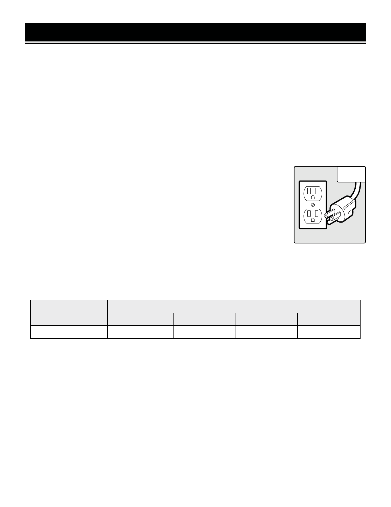
GROUNDING INSTRUCTIONS
In the event of a malfunction or breakdown, grounding provides the path of least resistance for an electric current
and reduces the risk of electric shock. This tool is equipped with an electric cord that has an equipment grounding
conductor and a grounding plug. The plug MUST be plugged into a matching outlet that is properly installed and
grounded in accordance with ALL local codes and ordinances.
1. Do not modify the plug provided. If it will not fit the outlet, have the proper outlet installed by a licensed electri-
cian.
2. Improper connection of the equipment grounding conductor can result in electric shock. The conductor with the
green insulation (with or without yellow stripes) is the equipment grounding conductor. If repair or replacement
of the electric cord or plug is necessary, DO NOT connect the equipment grounding conductor to a live terminal.
1. Examine extension cord before use. Make sure your extension cord is properly wired and in good condition.
Always replace a damaged extension cord or have it repaired by a qualified person before using it.
2. Do not abuse extension cord. Do not pull on cord to disconnect from receptacle; always disconnect by pulling
on plug. Disconnect the extension cord from the receptacle before disconnecting the product from the extension
cord. Protect your extension cords from sharp objects, excessive heat and damp/wet areas.
3. Use a separate electrical circuit for your tool. This circuit must not be less than a 12-gauge wire and should
be protected with a 15A time-delayed fuse. Before connecting the motor to the power line, make sure the switch
is in the OFF position and the electric current is rated the same as the current stamped on the motor nameplate.
Running at a lower voltage will damage the motor.
Fig. 1
GUIDELINES AND RECOMMENDATIONS FOR EXTENSION CORDS
When using an extension cord, be sure to use one heavy enough to carry the current your product will draw. An
undersized cord will cause a drop in line voltage resulting in loss of power and overheating. The table below shows
the correct size to be used according to cord length and ampere rating. When in doubt, use a heavier cord. The
smaller the gauge number, the heavier the cord.
UNPACKING
With the help of a friend or trustworthy foe, carefully remove the band saw from the packaging. Make sure to take
out all contents and accessories. Do not discard the packaging until everything is removed. Check the packing list
below to make sure you have all of the parts and accessories. If any part is missing or broken, please contact our
customer service at 1-847-429-9263 (M-F 8-5 CST), or email [email protected].
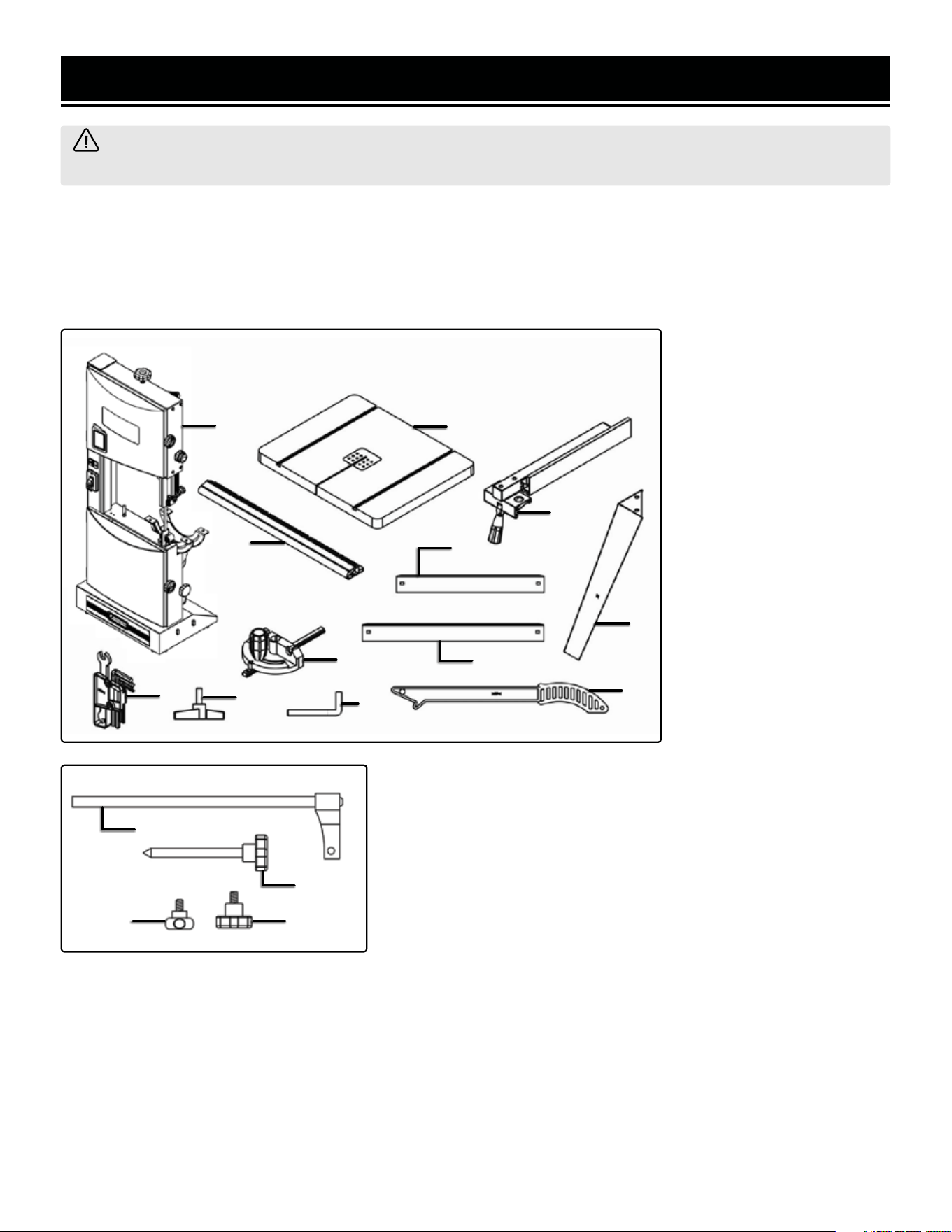
UNPACKING & PACKING LIST
WARNING! Do not plug in or turn on the tool until it is fully assembled according to the instructions. Failure
to follow the safety instructions may result in serious personal injury.
9
PACKING LIST
1. Band Saw (1)
2. Guide Rail (1)
3. Table with Insert (1)
4. Rip fence (1)
5. Short Brace (2)
6. Leg (4)
7. Long Brace (2)
8. Miter Gauge (1)
9. Accessory Tools (1)
10. Knob (4)
11. Hook with Hex Nut (1)
12. Push Stick (1)
Tools Required for Assembly & Adjustments
The tools listed below are not included but are required for either assembly or adjustment.
• Two 13mm Open End Wrenches
• One Phillips Head Screw Driver
• One Combination Square
1
3
2
8
10
9
5
7
6
4
11
12
Hardware Bag (Not Shown):
17. M8x12 Socket Head Bolts (8)
18. 8mm Flat Washers (12)
18. M6x12 Carriage Bolts (8)
20. 6mm Flat Washers (8)
21. M6 Hex Nut (8)
22. M4x10 Socket Head Bolts (2)
Circle Cutting Accessories:
13. Sliding Bracket
14. Center Pin
15. Lock Knob A
16. Lock Knob B
13
14
1615
10
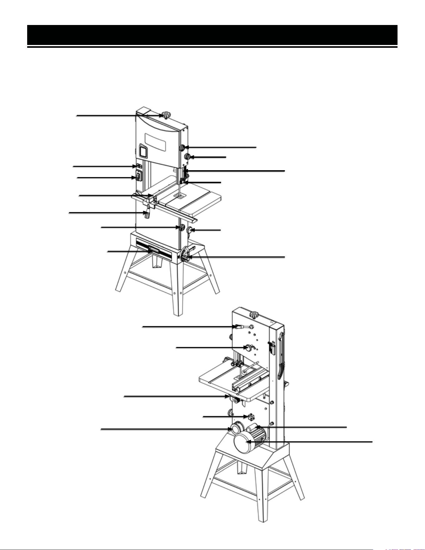
KNOW YOUR BAND SAW
TOOL PURPOSE
Band saws are used to cut wood. Refer to the following diagrams to become familiarized with all the parts and
controls of your band saw. The components will be referred to later in the manual for assembly and operation
instructions.
10
Tension Knob
Light Switch
Power Switch
Locking Fence
Fence Lock
Dust Collection Drawer
Upper Housing Knob
Blade Guard Adjustment Knob
Blade Guard
Blade Bearing Adjustment Knob
Blade Tension Adjustment Knob
Lower Housing Knob
Miter Gauge
Tension Release Lever
Blade Tracking Adjustment Knob
Table Bevel Lock
Lower Spindle Tracking Adjustment Knob
Dust Port
Capacitor Box
Motor
ASSEMBLY & ADJUSTMENTS
11
WARNING! Do not plug in or turn on the tool until it is fully assembled according to the instructions. Read
through and become familiarized with the following procedures of handling and adjusting your tool. Failure to
follow the safety instructions may result in serious personal injury.
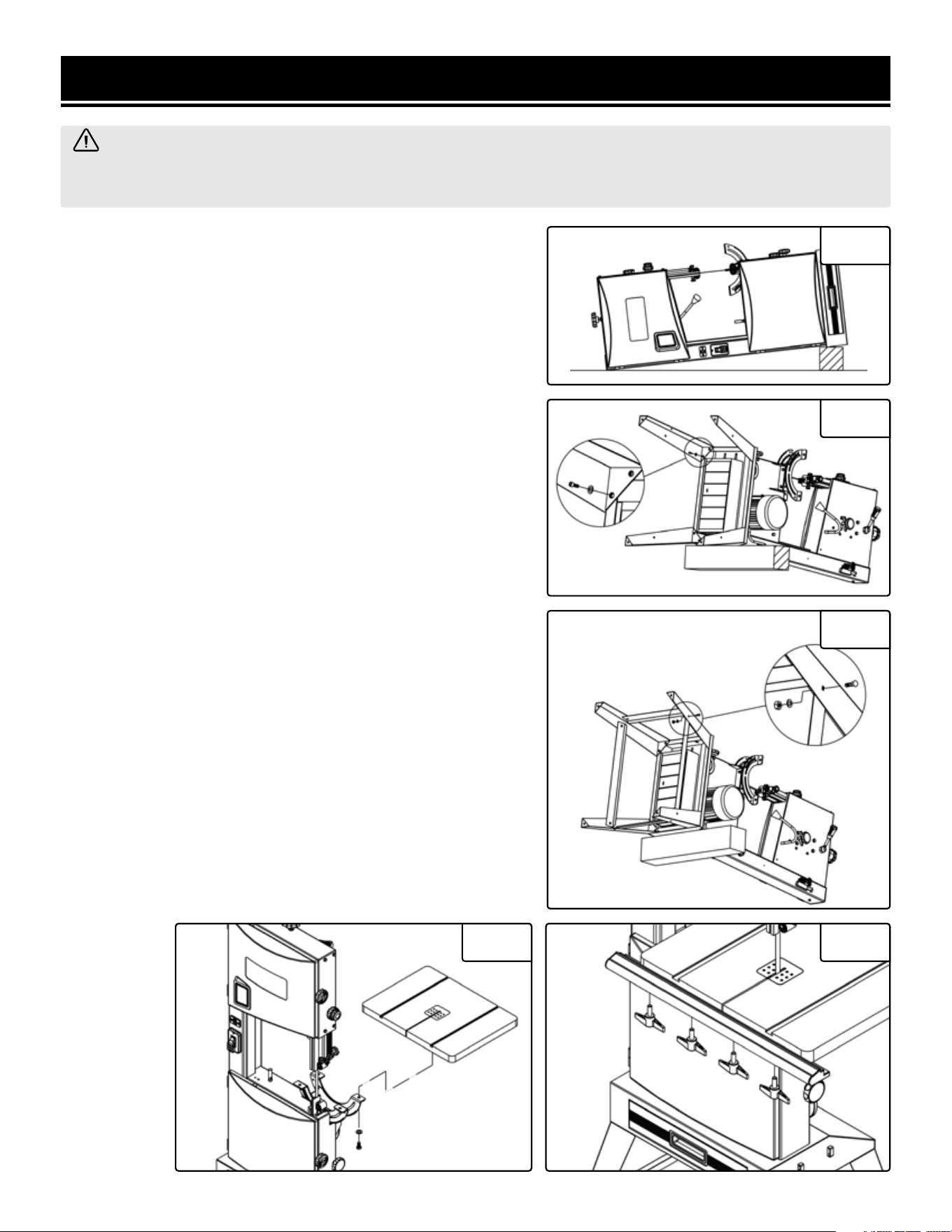
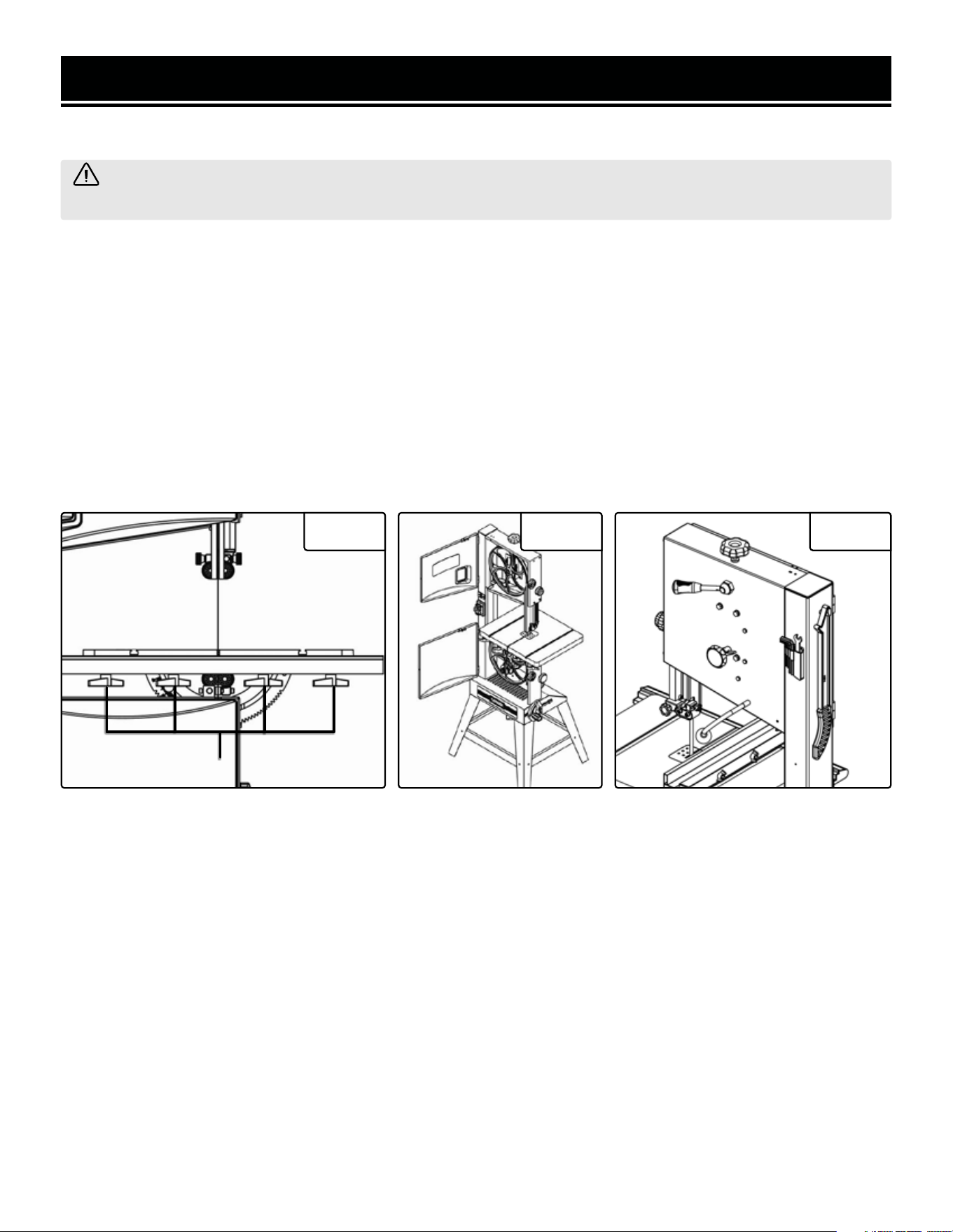
TO ASSEMBLE THE STAND
1. Carefully place the band saw on its back as shown above (Fig.
2), either on the floor or on a workbench. Prop the bottom of
the band saw up on a wooden block in order to have space to
assembly the band saw’s stand.
2. Attach legs to saw body using M8x12 socket head bolts and
8mm flat washers (Fig. 3).
3. Fix the short braces and the long braces by using M6x12
carriage bolts, 6mm flat washers and M6 hex nuts. DO NOT
TIGHTEN THE NUTS (Fig. 4).
4. Place the band saw upright and tighten all nuts. Make sure
there is no wobbling or tilting in the stand after fully tightening
the nuts.
TO ASSEMBLE THE TABLE
1. After attaching the stand, assemble the table to the bandsaw
by using M8x10 socket head bolts and 8mm flat washers (Fig.
5).
2. Make sure the saw blade is in the center of the table insert
slot.
3. Install the guide rail, securing it with the four knobs to the
table (Fig. 6).
Fig. 2
Fig. 3
Fig. 4
Fig. 5 Fig. 6
12
ASSEMBLY & ADJUSTMENTS
WARNING! Do not plug in or turn on the tool until it is fully assembled according to the instructions. Read
through and become familiarized with the following procedures of handling and adjusting your tool. Failure to
follow the safety instructions may result in serious personal injury.
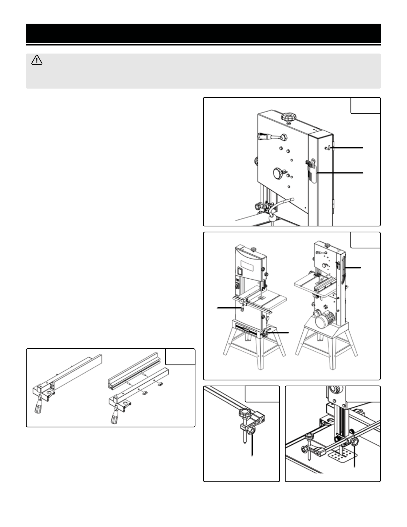
INSTALLING THE ACCESSORY TOOLS
1. Install the accessory tools assembly to the frame by
using M4x10 socket heat bolts (Fig. 7 - 1).
2. Secure the hook with a hex nut to the frame (Fig.
7 - 2).
3. Set the rip fence onto the table. Lock it in place with
the Fence Lock (Fig. 8 - 1).
NOTE: To reverse the rip fence, remove the fence from
the rip fence by loosening the four bolts holding it to
the rip fence, reversing the fence, and reattaching the
bolts. (Fig. 9)
4. Set the miter gauge into the onboard storage along
the base of the bandsaw (Fig. 8 - 2).
5. Set the push stick on the hook (Fig. 8 - 3, Fig. 7 - 2).
INSTALLING THE CIRCLE CUTTING GUIDE
1. Insert the center pin into the hole of the sliding
bracket. Fix it with Lock Knob A. This center pin will
serve as the pivot point for making circular cuts (Fig.
10).
2. Fix the sliding bar into the bearing bracket of the up-
per guard assembly. Slide it into the desired position
and secure it with tightening Lock Knob B (Fig. 11).
Fig. 7
Fig. 8
Fig. 9
Fig. 10 Fig. 11
2
1
1
2
3
Lock Knob A
Lock Knob B
13
ASSEMBLY & ADJUSTMENTS
WARNING! Always be sure that the tool is switched off and unplugged before making any adjustments.
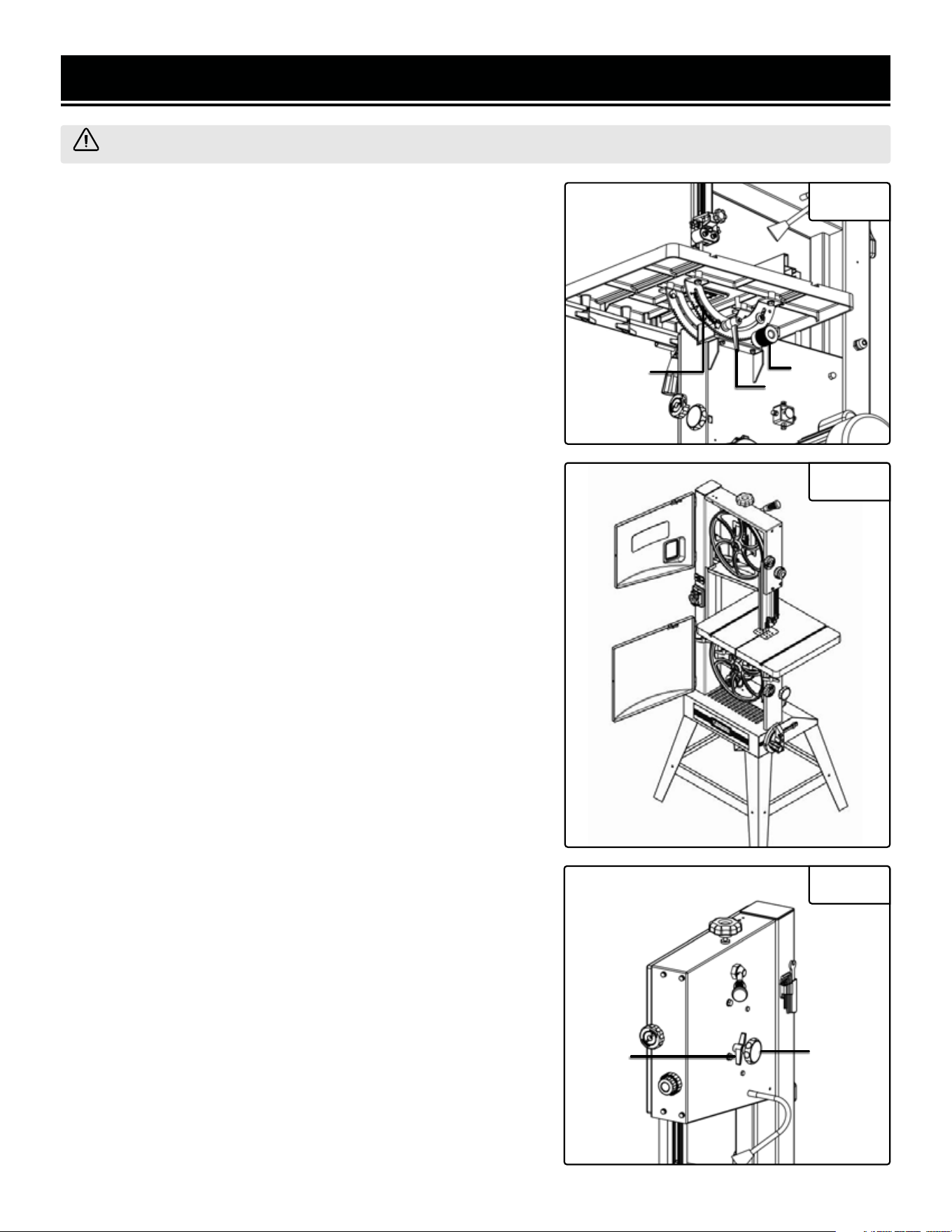
TILTING THE TABLE
1. Find and loosen the table bevel lock located in back under the
saw table (Fig. 12 - 1).
2. Adjust the table to the desired angle using the table tilting knob
(Fig. 12 - 2) and the angle indicator (Fig. 12 - 3).
3. Use the angle indicator to confirm the desired angle and tighten
the lock handle.
NOTE: A table perpendicular (90°) to the blade corresponds to a
scale indication of 0°).
ADJUSTING THE SAW BLADE
If the blade does not run in the middle of the rubber tire band, the
tracking needs to be corrected by adjusting the tilt of the upper
band saw wheel.
1. Turn of the bandsaw and unplug it from the power supply. Open
both the upper and lower wheel covers once the blade has stopped
moving (Fig. 13).
2. Loosen the tracking lock knob (Fig. 14 - 1) and manually rotate
the upper wheel, making sure not to touch the blade. Watch to see
which direction the blade tends to veer off towards in order to best
adjust the tracking set knob to resolve the problem.
3. Turn tracking set knob (Fig. 14 - 2) in the desired direction until
the blade is centered over the upper and lower wheels. Spin the
wheel manually to ensure that the blade is now running in the cen-
ter.
4. Tighten the tracking lock knob and close the covers (Fig. 14 - 1).
Fig. 12
1
2
3
Fig. 13
Fig. 14
1
2
14
ASSEMBLY & ADJUSTMENTS
WARNING! If the tension in the blade is too high, it runs the risk of breaking. If the tension is too low, there
is a risk of the blade slipping and stopping during a cut.
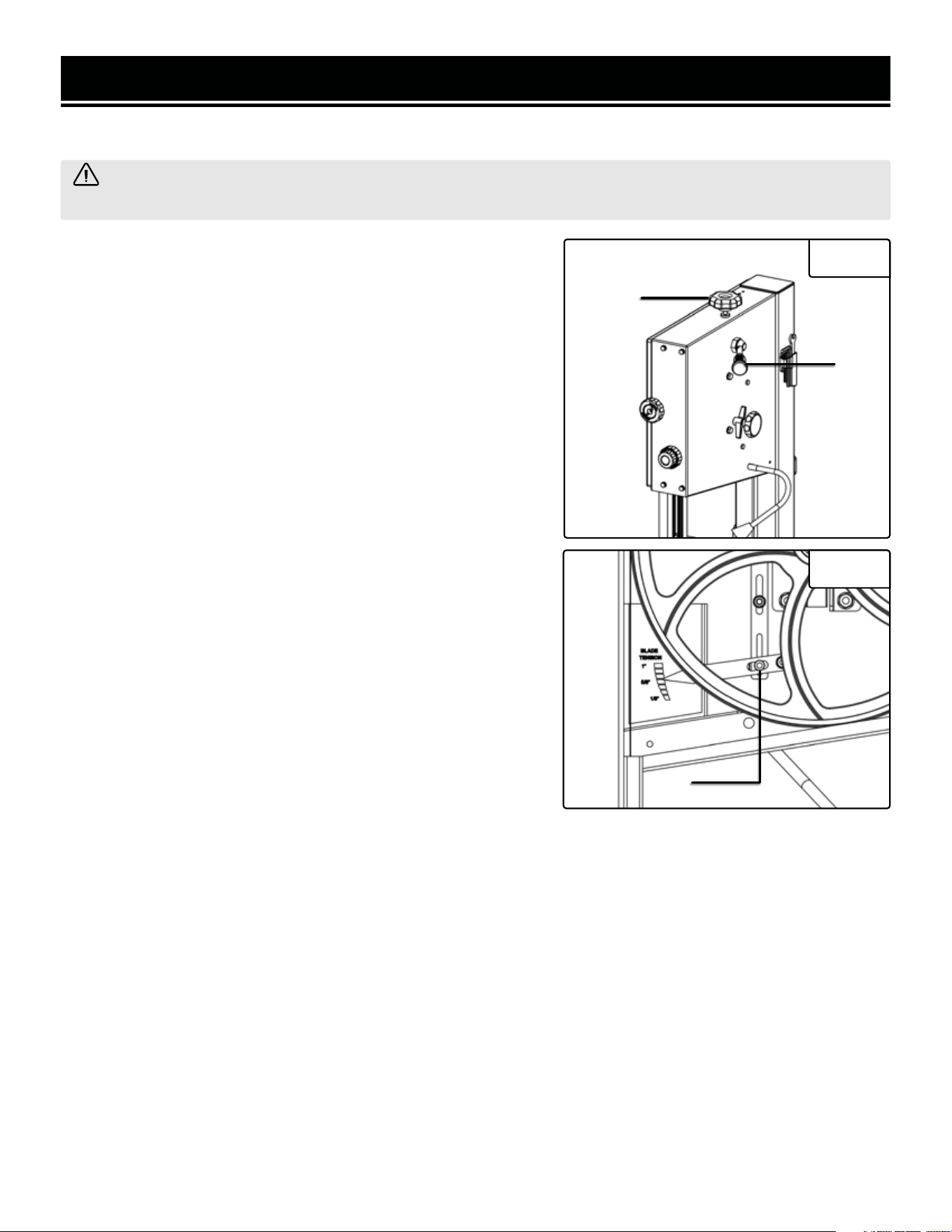
ADJUSTING BLADE TENSION
1. Raise the upper blade guide fully using the saw blade tension
knob located on the top of the machine (Fig. 15 - 1). Take the blade
width into consideration during the adjustment.
2. Check the tension by pushing with a finger against the side
of the blade halfway between the table and the upper guide. The
blade should not flex more than 2 mm.
3. Check the adjustment using the blade tension indicator on the
inside of the upper housing. The scale indicates the correct adjust-
ment for a certain width of blade. The indicator should be pointing
towards the width of blade being used.
4. Turning the setting knob clockwise increases the blade tension
while turning the setting knob counterclockwise decreases ten-
sion.
5. After achieving the desired tension, the tension release lever can
be used to easily loosen and tighten the spindles without changing
the amount of tension (Fig. 15 - 2).
ADJUSTING THE BLADE TENSION INDICATOR
The blade tension indicator can be adjusted for blades known to
be cut over or under length by different manufacturers. With mod-
erate tension on the blade, loosen the set screw (Fig. 16 - 1) and
adjust the blade indicator up or down as needed. Retighten the set
screw.
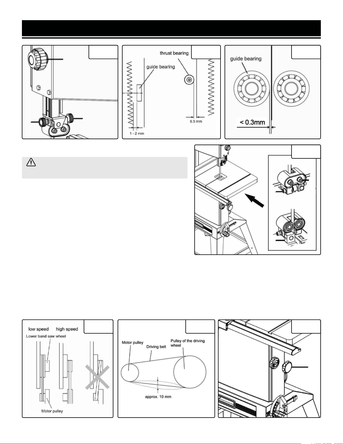
UPPER BLADE GUIDE ADJUSTMENT
Fig. 15
1
2
The height of the upper blade guard should be adjusted prior to every operation to accommodate the height of
the workpiece (the blade guard should be no more than one-fifth of an inch (3mm) from the upper edge of the
workpiece).
1. Use the adjustment knob (Fig. 17 - 1) to adjust the height of the upper blade guide. Use the outer locking knob
to secure the guard in place when it has reached the desired height.
2. Loosen the knobs on the side of the blade guard (Fig. 17 - 2 and 17 - 3) and adjust both the thrust and guide
bearings so that they are positioned approximately 1/10 of one inch (2mm) or less (0.5mm for the guide bearing)
away from the blade. The inside knob (Fig. 17 - 3) adjusts the thrust bearing, holding the back of the blade in place.
The outside knob (Fig. 17 - 2) adjusts the guide bearings, moving the blade left and right.
3. Once desired adjustments have been achieved (when the bearings are all roughly 0.1 to 0.5 mm away from the
blade) (Fig. 18, Fig. 19), tighten the knobs to secure the bearing guides in place.
Fig. 16
1
15
ASSEMBLY & ADJUSTMENTS
Fig. 17 Fig. 18 Fig. 19
WARNING! The lower blade guide must be adjusted
after every blade change and tracking adjustment.
LOWER BLADE GUIDE ADJUSTMENT
1. Loosen the set screw (Fig. 20 - 3) and move the entire lower
blade guide. Adjust the guide bearing to a position of 1 to 2
mm from the bottom of the blade. Retighten the set screw (Fig.
20 - 3).
2. Loosen the socket head bolt (Fig. 20 - 1) and adjust the
thrust bearing a position of .5 mm from the rear of the blade.
Retighten the bolt (Fig. 20 - 1).
3. Loosen the bolt (Fig. 20 - 2) and adjust the guide bearing to
a position .5 mm away from the blade. Retighten the bolt (Fig.
20 - 2).
Fig. 20
2
1
3
ADJUSTING THE CUTTING SPEED
1. Open the lower cover. Slacken the driving belt (Fig. 22) by turning the drive belt tension setting knob (Fig. 23 - 1)
clockwise.
2. Place the driving belt on the desired speed settings (Fig. 21) and retighten the drive belt tension setting knob.
Fig. 21 Fig. 22 Fig. 23
1
1
3
2
16
ASSEMBLY & ADJUSTMENTS
WARNING! The saw blade is dangerous. Be sure to wear gloves when handling the saw blade in any
situation.
CHANGING THE BAND SAW BLADE
1. Loosen the four lock knobs for the guide rail. Remove the guard rail by loosening the four lock knobs located
underneath (Fig. 24 - 1).
2. Open the upper cover and the lower cover. Set the upper blade guide to its lowest position.
3. Loosen the quick release lever until the bandsaw blade has sufficient enough slack.
4. Remove the bandsaw blade from the machine. Fit a fresh bandsaw blade and center the bandsaw blade on the
rubber tracking on each of the bandsaw wheels.
5. Tighten the quick release lever. After manually spinning the wheels to make sure the blade has been centered
properly, replace the guide rail to its original lever and close the upper and lower cover.
6. Align the saw blade, adjust the blade tension and adjust the upper and lower blade guides before operation.
Fig. 25 Fig. 26 Fig. 24
1
17
OPERATION
WARNINGS & SUGGESTIONS
• Do not touch the saw blade when cutting.
• During saw operation, wear safety glasses but do not wear gloves.
• Cut only one workpiece at a time.
• Always hold the workpiece down on the table.
• Do not jam any workpieces.
• Do not try to slow the blade down by pushing the work piece against the saw blade from the side.
• When straight cutting against the fence, use a push stick.
• Use a work support when cutting long stock to avoid pieces from falling down after the cut has been
completed.
• Use a dust collector and regularly empty the dust collection drawer.
• When cutting round stock, make sure the piece is a secure as possible.
• Before starting, check that the saw blade and the upper and lower blade guides are in proper working order.
• Replace damaged parts immediately.
• Assume the correct working position (the blade’s teeth should be pointing towards the operator).
• Take all necessary precautions to avoid kickback during operation.
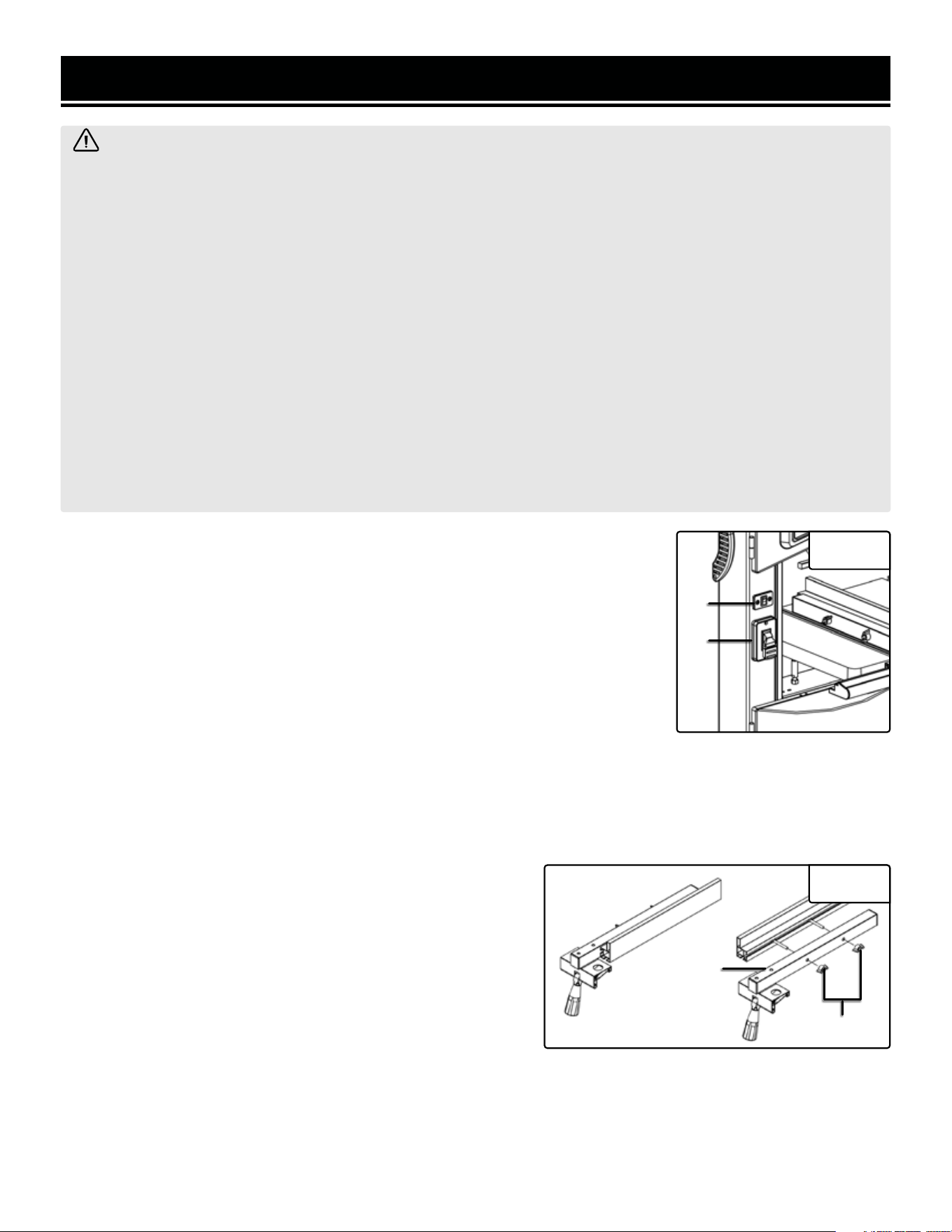
ON/OFF SWITCH
1. To turn the saw ON, move the switch to the up position (Fig. 27 - 1).
2. To turn the saw OFF, move the switch to the down (OFF) position.
3. To lock the switch in the OFF position:
a) Wait until the band saw has come to a complete stop.
b) Remove the safety key from the switch housing. Store the safety key in
a safe place.
4. To unlock the switch and turn the saw ON, insert the safety key into the switch,
and move the switch to the ON position.
Fig. 27
2
1
LED WORK LIGHT
The work light switch is independent and may be turned ON or OFF separately from the band saw switch. The LED
switch is a smaller switch located directly above the main ON/OFF switch (Fig. 27 - 2).
REVERSING THE RIP FENCE
The rip fence can be used on both sides of the blade. When the
rip fence is to be moved from one side of the saw blade to the
other, the fence needs to be reversed using the following steps:
1. Loosen and remove the two knobs (Fig. 28 - 1).
2. Take off the fence with bolts from the fence support.
3. Assemble fence with bolts to the other side of fence support.
4. Replace the two knobs.
To change the height of the fence, loosen the two knobs, slide the fence out from the fence support, rotate the fence
90°, insert the lock screw into the other groove of the fence, and finally retighten the two knobs.
The fence can be adjusted parallel with the side of the blade by loosening the two socket bolts (Fig. 28 - 2).
Fig. 28
1
2
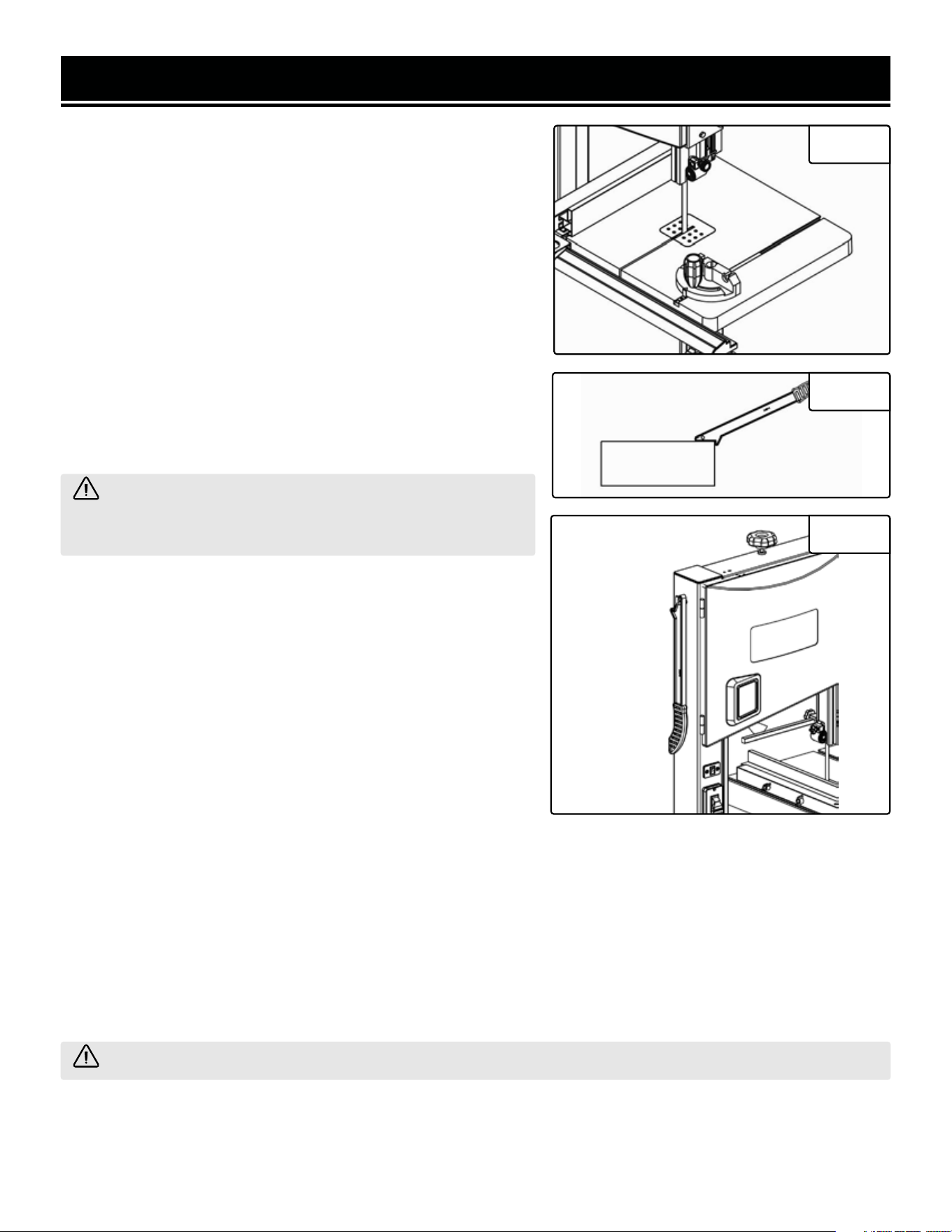
OPERATION
USING THE MITER GAUGE
1. Place the miter gauge into the slot on the table. (Fig. 29)
2. Loosen the knob on the gauge to set a new miter angle (be-
tween 0 and 60 degrees).
3. Tighten the knob firmly before cutting begins.
USING THE PUSH STICK
The push stick serves as an extension of the hand and protects
against accidental contact with the saw blade. The push stick
must be used if the distance between the bandsaw blade and the
rip fence is less than 5.9 inches. When the push stick is not used,
it can be stored on the hook provided on the bandsaw frame (Fig.
31). Replace the push stick if damaged.
GENERAL CUTTING
Fig. 29
Fig. 30
Fig. 31
WARNING! Operating a band saw involves a certain
amount of hazard. Read the instructions and plan your work
before cutting a workpiece.
1. Use scrap lumber to check the settings and to get the feel of
operating the band saw before attempting regular work.
2. Do not turn the power on before all adjustments have been
made. Check to make sure the upper guard is in place. Always
keep the upper blade guard close to your work, approximately
1/8” (3.2 mm) above the workpiece.
3. Do not force the workpiece against the blade. Light contact
permits easier cutting and prevents unwanted friction and heat-
ing of the blade. Sharp saw blades need little pressure for cutting.
Steadily move the workpiece against the blade without forcing it.
4. It is recommended that a dust collection bag be connected to
the dust port when sawing wood.
5. Use the band saw for straight line operations such as cross-cutting, ripping, miter cutting, beveling, compound
cutting, and resawing.
6. To avoid twisting the blade, do not turn sharp corners; instead, saw around corners. A band saw is basically a
“curve-cutting” saw. It is not capable of doing intricate inside cutting as can be done with a scroll saw.
WARNING! Do not use this band saw to cut ferrous metals.
18
OPERATION
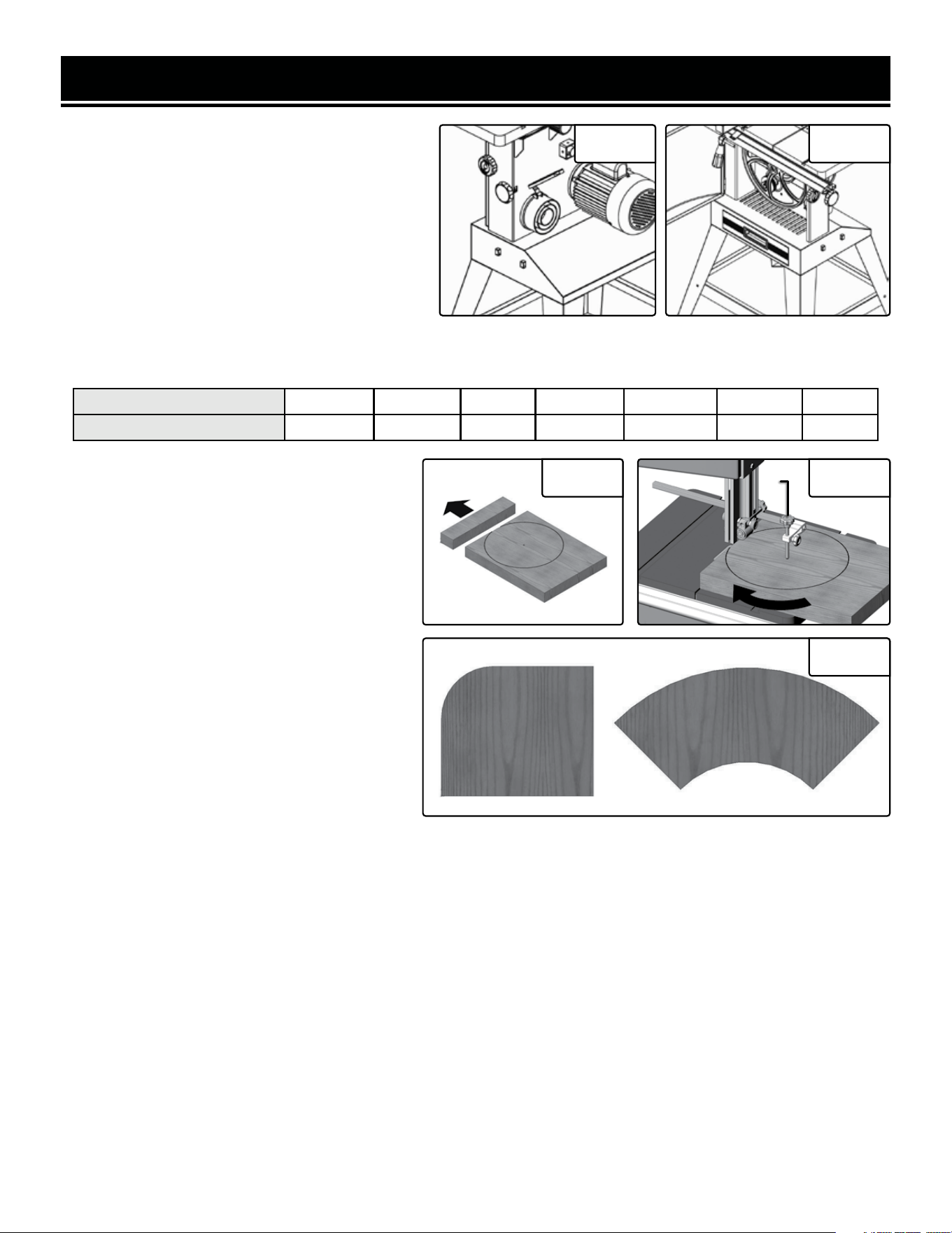
CONNECT A DUST COLLECTOR
The band saw provides a dust port for collecting
various size hoses. It should be connected with a
dust collector during any sawing operations. Ex-
cess debris gets collected into the dust drawer un-
derneath which should be routinely cleaned out.
Dust port sizes include 1-3/4 inches, 2-3/4 inches,
and 3-3/4 inches.
Fig. 32 Fig. 33
Blade Width 1/8 in. 3/16 in. 1/4 in. 3/8 in. 1/2 in. 3/4 in. 1 in.
Minimum Radius 3/16 in. 5/16 in. 5/8 in. 1-1/2 in. 2-1/2 in. 5-1/2 in. 7 in.
CUTTING CURVES WITH THE CIRCLE CUTTING GUIDE
To make a circular cut, use as narrow of a saw blade as is necessary for the radius of the circle.
1. Draw a circle and its center point on the
wood workpiece (Fig. 34).
2. Set the fence to the desired position where
the saw blade is in line to the tangent of the cir-
cle mark, keeping the wood work piece guided
by the fence. Turn on the bandsaw and cut off
the workpiece (Fig. 34).
3. Put the remainder of the workpiece with the
circle mark onto the table. Align the point of
tangency to the saw blade teeth. Set the center
pin in the center of the circle, fixing it in place
with the tightening knob (Fig. 35 - 1). Turn on
the bandsaw, slowly rotate and feed the work-
piece into the saw blade.
4. Aside from circles, this cutting accessory
can also help you easily cut out round corners
(Fig. 36).
Fig. 34 Fig. 35
Fig. 36
1
19

2120
ROUTINE INSPECTION
Before each use, inspect the general condition of the
tool. If any of these following conditions exist, do not
use until parts are replaced or the saw is properly re-
paired.
Check for:
• Loose hardware,
• Misalignment or binding of moving parts,
• Damaged cord/electrical wiring,
• Cracked or broken parts, and
• Any other condition that may affect its safe operation.
CLEANING & STORAGE
1. Keep the ventilation openings free from dust and
debris to prevent the motor from overheating. NOTE:
Always use a dust collection system. This will help pre-
vent sawdust from building up inside the band saw.
2. Wipe the tool surfaces clean with a clean cloth. Make
sure water does not get into the tool. Remove any pitch,
sap, or resin that has accumulated on the table, blade
guide, bearings, etc. using a damp cloth.
MAINTENANCE
WARNING! To avoid accidents, turn OFF and unplug the tool from the electrical outlet before cleaning,
adjusting, or performing any maintenance work.
WARNING! Any attempt to repair or replace electrical parts on this tool may be hazardous. Servicing of the
tool must be performed by a qualified technician. When servicing, use only identical WEN replacement parts.
Use of other parts may be hazardous or induce product failure.
CAUTION! Most plastics are susceptible to dam-
age from various types of commercial solvents. Do
not use any solvents or cleaning products that could
damage the plastic parts. Some of these include but
are not limited to: gasoline, carbon tetrachloride,
chlorinated cleaning solvents, and household deter-
gents that contain ammonia.
4. At least once a month, check the V-belt for proper
tension and any signs of wear.
5. Store the tool in a clean and dry place away from the
reach of children. Store in temperatures between 41° to
86°F.
6. Cover the band saw in order to protect it from dust
and moisture. Keep the instruction manual and all ac-
cessories nearby.
7. If you do not plan to use the band saw for a long pe-
riod of time (over 1 week), release tension on the blade.
This will help prolong blade life.
LUBRICATION
1. As needed, apply a light coat of good-quality paste
wax to the table. This will help provide a smooth gliding
surface for your workpieces.
2. As needed, apply a light coat of dry lubricant (PTFE
works well) to the space between the table bevel brack-
ets and the base bracket. This will help ensure that the
table bevels easily.
3. The bearings on your band saw are permanently
sealed and lubricated, and require no additional lubrica-
tion.
PRODUCT DISPOSAL
Used power tools should not be disposed of together
with household waste. This product contains electronic
components that should be recycled. Please take this
product to your local recycling facility for responsible
disposal and to minimize its environmental impact.
Please recycle the packaging and electronic
components where facilities exist.
3. At least once a month, open the doors and vacuum
out any accumulated dust, shavings, etc. Remove the
blade and clean off any built-up sawdust from the
wheels and tires using a stiff brush.
2120
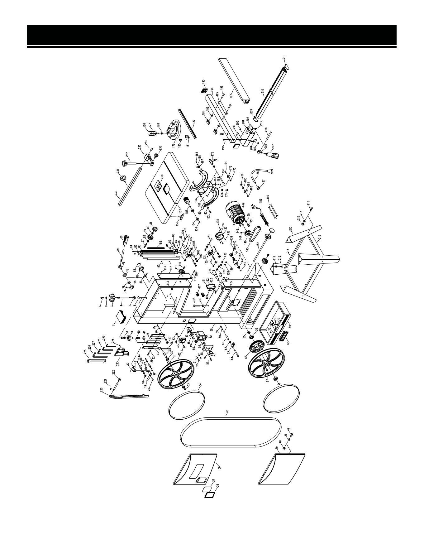
EXPLODED VIEW & PARTS LIST
NOTE: Not all parts may be available for purchase. Parts and accessories that wear
down over the course of normal use are not covered under the warranty.

EXPLODED VIEW & PARTS LIST
22
No. Part No. Description Qty.
1 3966-001 Socket head screw 1
2 3966-002 Flat washer 1
3 3966-003 Blade tension knob 1
4 3966-004 Screw 1
5 3966-005 Bushing 1
6 3966-006 Retaining ring 1
7 3966-007 Frame cap 1
8 3966-008 Hex nut 2
9 3966-009 Tension bracket 1
10 3966-010 Spring 1
11 3966-011 Nut 1
12 3966-012 Connecting plate 1
13 3966-013 Bolt 1
14 3966-014 Hex head bolt 3
15 3966-015 Flat washer 6
16 3966-016 Guide rod 3
17 3966-017 Nut 1
18 3966-018 Lock nut 3
19 3966-019 Blade tension pointer 1
20 3966-020 Bolt 1
21 3966-021 Retaining ring 2
22 3966-022 Shaft 1
23 3966-023 Guide plate 2
24 3966-024 Pulling plate 1
25 3966-025 Hex head bolt 4
26 3966-026 Flat washer 8
27 3966-027 Hex nut 4
28 3966-028 bevel block 1
29 3966-029 Shaft 1
30 3966-030 Ball bearing 4
31 3966-031 Retaining ring 4
32 3966-032 Upper wheel 2
33 3966-033 Retaining ring 2
34 3966-034 Tyre 2
35 3966-035 Blade 1
No. Part No. Description Qty.
36 3966-036 Upper cover 1
37 3966-037 Viewing window 1
38 3966-038 Window case 1
39 3966-039 Lower cover 1
40 3966-040 Lock nut 2
41 3966-041 Bushing 2
42 3966-042 Socket head screw 2
43 3966-043 Nut 1
44 3966-044 Flat washer 1
45 3966-045 LED driver 1
46 3966-046 Socket head screw 1
47 3966-047 Led switch box 1
48 3966-048 Switch cover 1
49 3966-049 Pan head screw 2
50 3966-050 LED switch 1
51 3966-051 Serrated washer 2
52 3966-052 Pan head screw 2
53 3966-053 Switch box 1
54 3966-054 Connecting terminal 3
55 3966-055
Thread forming
screw
1
56 3966-056 Main switch 1
57 3966-057 Pan head screw 2
58 BA1487-058 Frame 1
59 3966-059 Nut 1
60 3966-060 Flat washer 1
61 3966-061 Bushing 1
62 3966-062 Flat washer 1
63 3966-063 Brush 1
64 3966-064 Carriage blot 1
65 3966-065 Hex nut 1
66 3966-066 Spindle pulley 1
67 3966-067 Socket head screw 3
68 3966-068 Drawer handle 1
69 3966-069 Dust drawer 1

EXPLODED VIEW & PARTS LIST
23
No. Part No. Description Qty.
70 3966-070 Spring 1
71 3966-071 Ball 1
72 3966-072
Thread forming
screw
2
73 3966-073 Ball house 1
74 3966-074 Set screw 1
75 3966-075 Cam 1
76 3966-076 Bushing 1
77 3966-077 Nut 1
78 3966-078 Shaft 1
79 3966-079 Handle 1
80 3966-080 Handle cap 1
81 3966-081 Tracking set knob 1
82 3966-082 Tracking lock knob 1
83 3966-083 Cap 2
84 3966-084
Thread forming
screw
2
85 3966-085 Limiting plate 1
86 3966-086 Upper blade guard 1
87 3966-087 Shaft 1
88 3966-088 Gear 1
89 3966-089
Upper guide adjusting
knob
1
90 3966-090 Spring 1
91 3966-091 Lock knob 1
92 3966-092 Rack 1
93 3966-093 Sliding cover 1
94 3966-094 Socket head bolt 1
95 3966-095 Support block 1
96 3966-096 Connecting shaft 2
97 3966-097 Set screw 1
98 3966-098
Thread forming
screw
2
99 3966-099 Retaining ring 2
100 3966-100 Bearing 2
101 3966-101 Shaft 2
No. Part No. Description Qty.
102 3966-102 Knob 1
103 3966-103 Flat washer 1
104 3966-104 Socket head screw 2
105 3966-105 Flat washer 2
106 3966-106 Knob 1
107 3966-107 Guide block 1
108 3966-108 Shaft 4
109 3966-109 Ball bearing 8
110 3966-110 Socket head screw 2
111 3966-111 Cover lock knob 2
112 3966-112 Guide plate 1
113 3966-113 Lock nut 2
114 3966-114 Set screw 1
115 3966-115 Flat washer 4
116 3966-116 Hex head bolt 4
117 3966-117 Cord bushing 2
118 3966-118 Limiting shaft 1
119 3966-119 Hex nut 1
120 3966-120 Guide block 1
121 3966-121 Lower guard 1
122 3966-122 Hex head bolt 1
123 3966-123 Flat washer 2
124 3966-124 Shaft 1
125 3966-125 Hex nut 4
126 3966-126 Hex head bolt 4
127 3966-127 Hex nut 1
128 3966-128 Hex head bolt 1
129 3966-129 Hex head bolt 1
130 3966-130 Flat washer 2
131 3966-131 Guide block 1
132 3966-132 Set screw 1
133 3966-133 Socket head screw 1
134 3966-134 Socket head screw 1
135 3966-135 Pin 1
136 3966-136 Dust port cover 1

EXPLODED VIEW & PARTS LIST
24
EXPLODED VIEW & PARTS LIST
No. Part No. Description Qty.
137 3966-137 Dust port 1
138 3966-138 Pan head screw 3
139 3966-139 Set screw 1
140 3966-140 Bushing 1
141 3966-141 Idle pulley shaft 1
142 3966-142 Idle pulley 1
143 3966-143 Ball bearing 2
144 3966-144 Retaining ring 1
145 3966-145 Belt 1
146 3966-146 Motor pulley 1
147 3966-147 Set screw 1
148 3966-148 Key 1
149 3966-149 Motor 1
150 3966-150 Flat washer 4
151 3966-151 Socket head screw 4
152 3966-152 Belt tension knob 1
153 3966-153 Retaining ring 1
154 3966-154 Gear 2
155 3966-155 Table adjusting knob 1
156 3966-156 Lock knob 4
157 BA1487-157 Table 1
158 3966-158 Table insert 1
159 3966-159 Carriage blot 1
160 3966-160 Angle guide plate 2
161 3966-161 Table bevelling base 1
162 3966-162 Socket head bolt 2
163 3966-163 Flat washer 2
164 3966-164 Lock nut 2
165 3966-165 Pan head screw 1
166 3966-166 Flat washer 1
167 3966-167 Pointer 1
168 3966-168 Flat washer 4
169 3966-169 Hex head bolt 4
170 3966-170 Flat washer 4
171 3966-171 Socket head screw 4
No. Part No. Description Qty.
172 3966-172 Hex nut 4
173 3966-173 Limiting plate 1
174 3966-174 Hex head bolt 1
175 3966-175 Locking handle 1
176 3966-176 Cap 1
177 3966-177 Handle 1
178 3966-178 Washer 1
179 3966-179 Miter gauge 1
180 3966-180 Pan head screw 1
181 3966-181 Pointer 1
182 3966-182 Rod 1
183 3966-183 Socket head screw 1
184 3966-184 Cord clamp 1
185 3966-185 Flat washer 1
186 3966-186 Nut 1
187 3966-187 Hex nut 2
188 3966-188 LED driver 1
189 3966-189 Power cord 1
190 3966-190 Inner cord 2
191 3966-191 Knob 2
192 3966-192 Flat washer 2
193 3966-193 Fence support cap 2
194 3966-194 Fence support 1
195 3966-195 Guide plate 1
196 3966-196 Carriage blot 2
197 3966-197 Fence 1
198 3966-198 Socket head bolt 2
199 3966-199 Spacer plate 1
200 3966-200 Nut 3
201 3966-201 Sliding base 1
202 3966-202 Pointer 1
203 3966-203
Thread forming
screw
2
204 3966-204 Spring plate 1
205 3966-205 Pan head screw 1

25
EXPLODED VIEW & PARTS LISTEXPLODED VIEW & PARTS LIST
No. Part No. Description Qty.
206 3966-206 Lock block 1
207 3966-207 Lock handle 1
208 3966-208 Shaft 1
209 3966-209 Guide rail cap 1
210 3966-210 Guide rail 1
211 3966-211 Guide rail cap 1
212 3966-212 Flat washer 8
213 3966-213 Socket head screw 8
214 3966-214 Long brace 2
215 3966-215 Leg 4
216 3966-216 Hex nut 8
217 3966-217 Flat washer 8
218 3966-218 Carriage blot 8
219 3966-219 Short brace 2
220 3966-220 Push stick 1
No. Part No. Description Qty.
221 3966-221 Hook 1
222 3966-222 Hex nut 1
223 3966-223 Rack 1
224 3966-224 Pan head screw 2
225 3966-225 Spanner 1
226 3966-226 6mm hex wrench 1
227 3966-227 5mm hex wrench 1
228 3966-228 4mm hex wrench 1
229 3966-229 3mm hex wrench 1
230 3966-230 Sliding bar 1
231 3966-231 Locking knob 1
232 3966-232 Centre pin 1
233 3966-233 Support block 1
234 3966-234 Socket head screw 1
235 3966-235 Locking knob 1
NOTE: Not all parts may be available for purchase. Parts and accessories that wear
down over the course of normal use are not covered under the warranty.

WARRANTY
26
WEN Products is committed to building tools that are dependable for years. Our warranties are consistent with this
commitment and our dedication to quality.
LIMITED WARRANTY OF WEN PRODUCTS FOR HOME USE
GREAT LAKES TECHNOLOGIES, LLC (“Seller”) warrants to the original purchaser only, that all WEN consumer power
tools will be free from defects in material or workmanship during personal use for a period of two (2) years from date
of purchase or 500 hours of use; whichever comes first. Ninety days for all WEN products if the tool is used for pro-
fessional or commercial use. Purchaser has 30 days from the date of purchase to report missing or damaged parts.
SELLER’S SOLE OBLIGATION AND YOUR EXCLUSIVE REMEDY under this Limited Warranty and, to the extent per-
mitted by law, any warranty or condition implied by law, shall be the replacement of parts, without charge, which are
defective in material or workmanship and which have not been subjected to misuse, alteration, careless handling,
misrepair, abuse, neglect, normal wear and tear, improper maintenance, or other conditions adversely affecting the
Product or the component of the Product, whether by accident or intentionally, by persons other than Seller. To make
a claim under this Limited Warranty, you must make sure to keep a copy of your proof of purchase that clearly defines
the Date of Purchase (month and year) and the Place of Purchase. Place of Purchase must be a direct vendor of Great
Lakes Technologies, LLC. Purchasing through third party vendors, including but not limited to garage sales, pawn
shops, resale shops, or any other secondhand merchant, voids the warranty included with this product. Contact tech-
[email protected] or 1-847-429-9263 with the following information to make arrangements: your shipping
address, phone number, serial number, required part numbers, and proof of purchase. Damaged or defective parts
and products may need to be sent to WEN before the replacements can be shipped out.
Upon the confirmation of a WEN representative, your product may qualify for repairs and service work. When re-
turning a product for warranty service, the shipping charges must be prepaid by the purchaser. The product must
be shipped in its original container (or an equivalent), properly packed to withstand the hazards of shipment. The
product must be fully insured with a copy of the proof of purchase enclosed. There must also be a description of the
problem in order to help our repairs department diagnose and fix the issue. Repairs will be made and the product
will be returned and shipped back to the purchaser at no charge for addresses within the contiguous United States.
THIS LIMITED WARRANTY DOES NOT APPLY TO ITEMS THAT WEAR OUT FROM REGULAR USAGE OVER TIME,
INCLUDING BELTS, BRUSHES, BLADES, BATTERIES, ETC. ANY IMPLIED WARRANTIES SHALL BE LIMITED IN DU-
RATION TO TWO (2) YEARS FROM DATE OF PURCHASE. SOME STATES IN THE U.S. AND SOME CANADIAN PROV-
INCES DO NOT ALLOW LIMITATIONS ON HOW LONG AN IMPLIED WARRANTY LASTS, SO THE ABOVE LIMITATION
MAY NOT APPLY TO YOU.
IN NO EVENT SHALL SELLER BE LIABLE FOR ANY INCIDENTAL OR CONSEQUENTIAL DAMAGES (INCLUDING BUT
NOT LIMITED TO LIABILITY FOR LOSS OF PROFITS) ARISING FROM THE SALE OR USE OF THIS PRODUCT. SOME
STATES IN THE U.S. AND SOME CANADIAN PROVINCES DO NOT ALLOW THE EXCLUSION OR LIMITATION OF IN-
CIDENTAL OR CONSEQUENTIAL DAMAGES, SO THE ABOVE LIMITATION OR EXCLUSION MAY NOT APPLY TO YOU.
THIS LIMITED WARRANTY GIVES YOU SPECIFIC LEGAL RIGHTS, AND YOU MAY ALSO HAVE OTHER RIGHTS
WHICH VARY FROM STATE TO STATE IN THE U.S., PROVINCE TO PROVINCE IN CANADA AND FROM COUNTRY TO
COUNTRY.
THIS LIMITED WARRANTY APPLIES ONLY TO ITEMS SOLD WITHIN THE UNITED STATES OF AMERICA, CANADA
AND THE COMMONWEALTH OF PUERTO RICO. FOR WARRANTY COVERAGE WITHIN OTHER COUNTRIES, CON-
TACT THE WEN CUSTOMER SUPPORT LINE. FOR WARRANTY PARTS OR PRODUCTS REPAIRED UNDER WARRAN-
TY SHIPPING TO ADDRESSES OUTSIDE OF THE CONTIGUOUS UNITED STATES, ADDITIONAL SHIPPING CHARGES
MAY APPLY.

27
NOTES

V. 2025.03.19
THANKS FOR
REMEMBERING