EXEO ST OWNER’S MANUAL
Inglés 3R9012003AM (07.10) (GT9)
EXEO ST Inglés (07.10)
3R9012003AM
Portada EXEO ST.qxd:Maquetación 1 23/7/10 08:38 Página 3
SEAT S.A. is permanently concerned about continuous development of its types and models. For this reason we ask you to understand,
that at any given time, changes regarding shape, equipment and technique may take place on the car delivered. For this reason no
right at all may derive based on the data, drawings and descriptions in this current handbook.
All texts, illustrations and standards in this handbook are based on the status of information at the time of printing. Except for error
or omission, the information included in the current handbook is valid as of the date of closing print.
Re-printing, copying or translating, whether total or partial is not allowed unless SEAT allows it in written form.
SEAT reserves all rights in accordance with the "Copyright" Act.
All rights on changes are reserved.
;
This paper has been manufactured using bleached non-chlorine cellulose.
© SEAT S.A. - Reprint: 15.09.10
Portada EXEO ST_interior.qxd:maquetación 23/7/10 08:37 Página 3

Foreword
This Instruction Manual and its corresponding supplements should be read carefully to familiarise yourself with
your vehicle.
Besides the regular care and maintenance of the vehicle, its correct handling will help preserve its value.
For safety reasons, note the information concerning accessories, modifications and part replacements.
If selling the vehicle, give all of the on-board documentation to the new owner, as it should be kept with the
vehicle.
ExeoST_EN.book Seite 1 Freitag, 3. September 2010 11:41 11

ExeoST_EN.book Seite 2 Freitag, 3. September 2010 11:41 11

Contents 3
Contents
Manual structure . . . . . . . . . . . . . . . . . . . .
Content . . . . . . . . . . . . . . . . . . . . . . . . . . . . . . . .
Safety First . . . . . . . . . . . . . . . . . . . . . . . . . . .
Safe driving . . . . . . . . . . . . . . . . . . . . . . . . . . . . . .
Brief introduction . . . . . . . . . . . . . . . . . . . . . . . .
Proper sitting position for occupants . . . . . . . . .
Pedal area . . . . . . . . . . . . . . . . . . . . . . . . . . . . . .
Storing objects . . . . . . . . . . . . . . . . . . . . . . . . . .
Seat belts . . . . . . . . . . . . . . . . . . . . . . . . . . . . . . . .
Brief introduction . . . . . . . . . . . . . . . . . . . . . . . .
Why wear seat belts? . . . . . . . . . . . . . . . . . . . . . .
Seat belts . . . . . . . . . . . . . . . . . . . . . . . . . . . . . . .
Seat belt tensioners . . . . . . . . . . . . . . . . . . . . . .
Airbag system . . . . . . . . . . . . . . . . . . . . . . . . . . . .
Brief introduction . . . . . . . . . . . . . . . . . . . . . . . .
Front airbags . . . . . . . . . . . . . . . . . . . . . . . . . . . .
Knee airbag* . . . . . . . . . . . . . . . . . . . . . . . . . . . .
Side airbags* . . . . . . . . . . . . . . . . . . . . . . . . . . . .
Curtain airbags . . . . . . . . . . . . . . . . . . . . . . . . . .
Deactivating airbags . . . . . . . . . . . . . . . . . . . . . .
Child safety . . . . . . . . . . . . . . . . . . . . . . . . . . . . . .
Brief introduction . . . . . . . . . . . . . . . . . . . . . . . .
Child seats . . . . . . . . . . . . . . . . . . . . . . . . . . . . . .
Securing child seats . . . . . . . . . . . . . . . . . . . . . .
Operating Instructions . . . . . . . . . . . .
Cockpit . . . . . . . . . . . . . . . . . . . . . . . . . . . . . . . . . . .
Overview . . . . . . . . . . . . . . . . . . . . . . . . . . . . . . .
Instruments . . . . . . . . . . . . . . . . . . . . . . . . . . . . .
Warning and indicator lamps . . . . . . . . . . . . . . .
Driver information system . . . . . . . . . . . . . . . . . .
Auto-check system . . . . . . . . . . . . . . . . . . . . . . .
Speed warning* . . . . . . . . . . . . . . . . . . . . . . .
Onboard computer . . . . . . . . . . . . . . . . . . . . . . .
Menu display . . . . . . . . . . . . . . . . . . . . . . . . . . . .
Tyre pressure monitoring* . . . . . . . . . . . . . . . . .
Steering wheel controls . . . . . . . . . . . . . . . . . . .
Multifunction steering wheel* . . . . . . . . . . . . . .
Unlocking and locking . . . . . . . . . . . . . . . . . . . .
Remote control keys . . . . . . . . . . . . . . . . . . . . . .
Central locking . . . . . . . . . . . . . . . . . . . . . . . . . . .
Tailgate . . . . . . . . . . . . . . . . . . . . . . . . . . . . . . . . .
Childproof lock . . . . . . . . . . . . . . . . . . . . . . . . . .
Remote control key . . . . . . . . . . . . . . . . . . . . . . .
Anti-theft alarm system* . . . . . . . . . . . . . . . . . . .
Electric windows . . . . . . . . . . . . . . . . . . . . . . . . .
Sliding/tilting sunroof* . . . . . . . . . . . . . . . . . . . .
Lights and visibility . . . . . . . . . . . . . . . . . . . . . . .
Lights . . . . . . . . . . . . . . . . . . . . . . . . . . . . . . . . . .
Interior lights . . . . . . . . . . . . . . . . . . . . . . . . . . . .
Visibility . . . . . . . . . . . . . . . . . . . . . . . . . . . . . . . .
Windscreen wipers . . . . . . . . . . . . . . . . . . . . . . .
Rear view mirrors . . . . . . . . . . . . . . . . . . . . . . . . .
Seats and storage compartments . . . . . . . . . .
Manual adjustment of the front seats . . . . . . . .
Electric adjustment of front seats* . . . . . . . . . . .
Lumbar support* . . . . . . . . . . . . . . . . . . . . . . . . .
Driver seat memory* . . . . . . . . . . . . . . . . . . . . . .
Head restraints . . . . . . . . . . . . . . . . . . . . . . . . . .
Armrests . . . . . . . . . . . . . . . . . . . . . . . . . . . . . . . .
Luggage compartment . . . . . . . . . . . . . . . . . . . .
Roof rack / roof rails* . . . . . . . . . . . . . . . . . . . . .
Drink holder . . . . . . . . . . . . . . . . . . . . . . . . . . . . .
Ashtray*, cigarette lighter* and electric sockets*
Compartments . . . . . . . . . . . . . . . . . . . . . . . . . . .
Air conditioning . . . . . . . . . . . . . . . . . . . . . . . . . .
2C-Climatronic . . . . . . . . . . . . . . . . . . . . . . . . . . .
Driving . . . . . . . . . . . . . . . . . . . . . . . . . . . . . . . . . . .
Steering . . . . . . . . . . . . . . . . . . . . . . . . . . . . . . . .
Safety . . . . . . . . . . . . . . . . . . . . . . . . . . . . . . . . . .
Ignition lock . . . . . . . . . . . . . . . . . . . . . . . . . . . . .
Starting and stopping the engine . . . . . . . . . . .
Handbrake . . . . . . . . . . . . . . . . . . . . . . . . . . . . . .
Parking aid acoustic system . . . . . . . . . . . . . . . .
Cruise control* . . . . . . . . . . . . . . . . . . . . . . . . . . .
Manual gearbox . . . . . . . . . . . . . . . . . . . . . . . . . .
Automatic gearbox* . . . . . . . . . . . . . . . . . . . . . .
Practical Tips . . . . . . . . . . . . . . . . . . . . . . . .
Intelligent technology . . . . . . . . . . . . . . . . . . . . .
Electronic Stability Programme (ESP) . . . . . . . .
Brakes . . . . . . . . . . . . . . . . . . . . . . . . . . . . . . . . .
Power steering . . . . . . . . . . . . . . . . . . . . . . . . . . .
Servotronic* . . . . . . . . . . . . . . . . . . . . . . . . . . . . .
Driving and the environment . . . . . . . . . . . . . .
Running-in . . . . . . . . . . . . . . . . . . . . . . . . . . . . . .
Exhaust gas purification system . . . . . . . . . . . . .
5
6
7
7
7
10
15
16
18
18
19
22
26
28
28
32
35
38
41
44
46
46
48
51
57
57
57
59
65
71
75
82
85
87
89
91
91
96
96
98
103
104
105
107
109
112
116
116
124
127
128
131
134
134
136
137
138
140
142
143
151
153
154
159
162
162
172
172
172
173
174
176
177
180
183
183
191
191
191
194
196
196
197
197
198
ExeoST_EN.book Seite 3 Freitag, 3. September 2010 11:41 11

Contents4
Economical and environmentally friendly driving
Driving abroad . . . . . . . . . . . . . . . . . . . . . . . . . . .
Trailer towing . . . . . . . . . . . . . . . . . . . . . . . . . . . . .
Trailer towing . . . . . . . . . . . . . . . . . . . . . . . . . . . .
Removable towing bracket . . . . . . . . . . . . . . . . .
Vehicle maintenance and cleaning . . . . . . . .
General notes . . . . . . . . . . . . . . . . . . . . . . . . . . .
Vehicle exterior maintenance . . . . . . . . . . . . . . .
Vehicle interior maintenance . . . . . . . . . . . . . . .
Accessories, parts replacement and
modifications
. . . . . . . . . . . . . . . . . . . . . . . . . . . .
Accessories and spare parts . . . . . . . . . . . . . . . .
Technical modifications . . . . . . . . . . . . . . . . . . .
Mobile phones and two-way radios . . . . . . . . . .
Athermic windscreen* . . . . . . . . . . . . . . . . . . . . .
Checking and refilling levels . . . . . . . . . . . . . .
Refuelling . . . . . . . . . . . . . . . . . . . . . . . . . . . . . . .
Petrol . . . . . . . . . . . . . . . . . . . . . . . . . . . . . . . . . .
Diesel . . . . . . . . . . . . . . . . . . . . . . . . . . . . . . . . . .
Bonnet . . . . . . . . . . . . . . . . . . . . . . . . . . . . . . . . .
Engine oil . . . . . . . . . . . . . . . . . . . . . . . . . . . . . . .
Cooling system . . . . . . . . . . . . . . . . . . . . . . . . . .
Washer fluid and windscreen wiper blades . . . .
Brake fluid . . . . . . . . . . . . . . . . . . . . . . . . . . . . . .
Vehicle battery . . . . . . . . . . . . . . . . . . . . . . . . . . .
Wheels and tyres . . . . . . . . . . . . . . . . . . . . . . . . .
Wheels . . . . . . . . . . . . . . . . . . . . . . . . . . . . . . . . .
If and when . . . . . . . . . . . . . . . . . . . . . . . . . . . . . .
Tools, tyre repair kit and spare wheel . . . . . . . .
Changing a wheel . . . . . . . . . . . . . . . . . . . . . . . .
Tyre repairs* (Tyre Mobility System) . . . . . . . . . .
Fuses . . . . . . . . . . . . . . . . . . . . . . . . . . . . . . . . . .
Bulbs . . . . . . . . . . . . . . . . . . . . . . . . . . . . . . . . . .
Changing bulbs. Halogen headlights . . . . . . . .
Changing bulbs. Bi-Xenon AFS headlights . . . .
Changing tail light bulbs (on side panel) . . . . .
Changing tail light bulbs (on tailgate) . . . . . . . .
Side turn signals . . . . . . . . . . . . . . . . . . . . . . . . .
Luggage compartment lights . . . . . . . . . . . . . . .
Registration light . . . . . . . . . . . . . . . . . . . . . . . . .
Sun visor light . . . . . . . . . . . . . . . . . . . . . . . . . . .
Jump-starting . . . . . . . . . . . . . . . . . . . . . . . . . . . .
Towing and tow-starting . . . . . . . . . . . . . . . . . . .
Technical Specifications . . . . . . . . . .
Description of specifications . . . . . . . . . . . . . .
Important information . . . . . . . . . . . . . . . . . . . . .
Information on fuel consumption . . . . . . . . . . . .
Towing a trailer . . . . . . . . . . . . . . . . . . . . . . . . . .
Wheels . . . . . . . . . . . . . . . . . . . . . . . . . . . . . . . . .
Technical Specifications . . . . . . . . . . . . . . . . . .
Checking fluid levels . . . . . . . . . . . . . . . . . . . . . .
Petrol engine 1.8 88 kW (120 PS) . . . . . . . . . . .
Petrol engine 1.8 118 kW (160 PS) . . . . . . . . . .
Petrol engine 2.0 147 kW (200 PS) . . . . . . . . . .
Petrol engine 2.0 155 kW (210 PS) . . . . . . . . . .
Diesel engine 2.0 TDI CR 88 kW (120 PS) . . . . .
Diesel engine 2.0 TDI CR 105 kW (143 PS) . . . .
Diesel engine 2.0 TDI CR 125 kW (170 PS) . . . .
Dimensions and capacities . . . . . . . . . . . . . . . .
Index . . . . . . . . . . . . . . . . . . . . . . . . . . . . . . . . . .
199
201
203
203
206
214
214
215
220
223
223
223
224
224
225
225
226
227
228
230
233
236
240
241
245
245
254
254
257
262
265
267
267
274
280
285
288
289
290
291
291
294
297
297
297
299
299
300
301
301
302
303
304
305
307
308
309
311
313
ExeoST_EN.book Seite 4 Freitag, 3. September 2010 11:41 11
Manual structure 5
Manual structure
What you should know before reading this manual
This manual contains a description of the equipment supplied with the
vehicle at the time of press. Some of the equipment hereunder described will
not be available until a later date, or is only available in certain markets.
As this is a general manual for the EXEO ST, some of the equipment and func-
tions described in this manual are not included in all types or versions of the
model. These may vary or be modified depending on technical and market
requirements, which can in no way be interpreted as deceptive advertising.
The illustrations are intended as a general guide and may vary from the
equipment fitted in your vehicle in some details.
The direction indications (left, right, front, rear) appearing in this manual
refer to the normal forward working direction of the vehicle except when
otherwise indicated.
The equipment marked with an asterisk** is fitted as standard only in certain
versions, and is only supplied as optional extras for some versions, or are
only offered in certain countries.
® All registered marks are indicated with ®. Although the copyright symbol
does not appear, it is a copyrighted mark.
b The section is continued on the following page.
Marks the end of a section.
WARNING
Texts preceded by this symbol contain information on safety. They warn
you about possible dangers of accident or injury.
Caution
Texts with this symbol draw your attention to potential sources of damage to
your vehicle.
For the sake of the environment
Texts preceded by this symbol contain additional information on the protec-
tion of the environment.
Note
Texts preceded by this symbol contain additional information.
ExeoST_EN.book Seite 5 Freitag, 3. September 2010 11:41 11

Content6
Content
This manual is structured to provide the information you need in an organised
way. The content of this Manual is divided into sections which belong to
chapters(e.g.“Air conditioning”). The entire manual is divided into five large
parts which are:
1. Safety first
Information on the vehicle equipment relating to passive safety such as seat
belts, airbags, seats, etc.
2. Operating instructions
Information about the distribution of controls in the driver position of your
vehicle, about the seat adjustment possibilities, about how to create a suit-
able climate in the passenger compartment, etc.
3. Practical tips
Advice relating to the driving, caring and maintenance of your vehicle and
certain problems you can solve yourself.
4. Technical Specifications
Figures, values and the dimensions of your vehicle.
5. Alphabetic index
At the end of this manual there is a detailed alphabetical index, this will help
you to rapidly find the information you require.
ExeoST_EN.book Seite 6 Freitag, 3. September 2010 11:41 11
Safe driving 7
Safety First Operating Instructions Practical Tips Technical Specifications
Safety First
Safe driving
Brief introduction
Dear SEAT Driver
Safety first!
This chapter contains important information, tips, suggestions and
warnings that you should read and consider for both your own safety
and for your passengers' safety.
WARNING
• This manual contains important information about the operation of the
vehicle, both for the driver and the passengers. The other sections of the
owner's manual also contain further information that you should be aware
of for your own safety and for the safety of your passengers.
• Ensure that the on-board documentation is kept in the vehicle at all
times. This is especially important when lending or selling the vehicle to
another person.
Safety equipment
The safety equipment listed here are part of the vehicle's
passenger restraint system. They work together to help
reduce the risk of injury in a wide variety of accident situa-
tions.
Your safety and the safety of your passengers should not be left to chance. In
the event of an accident, the safety features incorporated in your vehicle are
capable of reducing the risk of injury. These are just a few of the safety
features in your SEAT:
• Three-point seat belts optimised for all seats
• Belt force limiters for the seats
• Belt tension devices for the front seat belts
• Front airbags
• Side airbags in the front and rear seat backrests*
• Head-protection airbags*
• Knee airbag for left-hand drive only
• ISOFIX anchor points* for ISOFIX child safety seats on the outer rear seats
• Height-adjustable head restraints
• Adjustable steering column
These individual safety features are harmonised to provide you and your
passengers with the best possible protection in case of an accident. However,
they can only be effective if you and your passengers sit in the correct posi-
tion and adjust and use the safety equipment properly.
ExeoST_EN.book Seite 7 Freitag, 3. September 2010 11:41 11

Safe driving8
Therefore, this chapter explains why these safety features are so important,
how they can protect you, what you need to remember when using them and
how you and your passengers can gain the most benefit from them. There are
also a number of important safety warnings that you and your passengers
should always observe in order to minimise the risk of injury.
Safety is everyone's responsibility!
Before setting off
The driver is responsible for the safety of the passengers and
the safe operation of the vehicle at all times.
For your own safety and the safety of your passengers, always note
the following points before setting off:
– Make sure that all lights and indicators are working properly.
– Check tyre pressure.
– Make sure that all windows are clean and give good visibility to
the outside.
– Secure all luggage and other items carefully ⇒ page 16.
– Make sure that no objects can interfere with the pedals.
– Adjust the front seat, head restraint and mirrors correctly.
– Make sure that the head restraints for all passengers are
adjusted to the correct position.
– Make sure that children are protected with suitable safety seats
and properly worn seat belts ⇒ page 46.
– Sit in a correct position. Inform your passengers as to how they
should sit ⇒ page 10.
– Fasten your seat belt correctly. Make sure that your passengers
do the same ⇒ page 18.
What affects safe driving?
Safety on the road is directly related to how you drive, and can
also be affected by the passengers in the vehicle.
The driver is responsible for the safety of the vehicle and all its occu-
pants. If your ability to drive is impaired in any way, you endanger
yourself and other road users ⇒ . Therefore:
– Do not let yourself be distracted by passengers or by using a
mobile phone, etc.
– Never drive when your driving ability is impaired (by medication,
alcohol, drugs, etc.).
– Obey all traffic regulations and speed limits and always maintain
a safe distance to the vehicle in front.
– Always adjust your speed to suit the road, traffic and weather
conditions.
– Take frequent breaks on long trips. Do not drive for more than two
hours without a stop.
– If possible, avoid driving when you are tired or stressed.
ExeoST_EN.book Seite 8 Freitag, 3. September 2010 11:41 11

Safe driving 9
Safety First Operating Instructions Practical Tips Technical Specifications
WARNING
When driving safety is impaired during a trip, the risk of injury and acci-
dents increases.
What affects driving safety?
Driving safety is largely determined by your driving style and
the personal behaviour of all occupants.
As a driver, you are responsible for yourself and your passengers.
When your concentration or driving safety is affected by any circum-
stance, you endanger yourself as well as others on the road ⇒ ,
for this reason:
– Always pay attention to traffic and do not get distracted by
passengers or telephone calls.
– Never drive when your driving ability is impaired (e.g. by medica-
tion, alcohol, drugs).
– Observe traffic laws and speed limits.
– Always reduce your speed as appropriate for road, traffic and
weather conditions.
– When travelling long distances, take breaks regularly - at least
every two hours.
– If possible, avoid driving when you are tired or stressed.
WARNING
When driving safety is impaired during a trip, the risk of injury and acci-
dents increases.
ExeoST_EN.book Seite 9 Freitag, 3. September 2010 11:41 11
Safe driving10
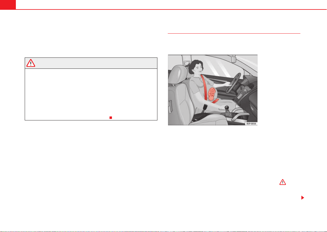
Proper sitting position for occupants
Proper sitting position for driver
The proper sitting position for the driver is important for a
safe and relaxed driving.
For your own safety and to reduce the risk of injury in the event of an
accident, we recommend the following adjustments for the driver:
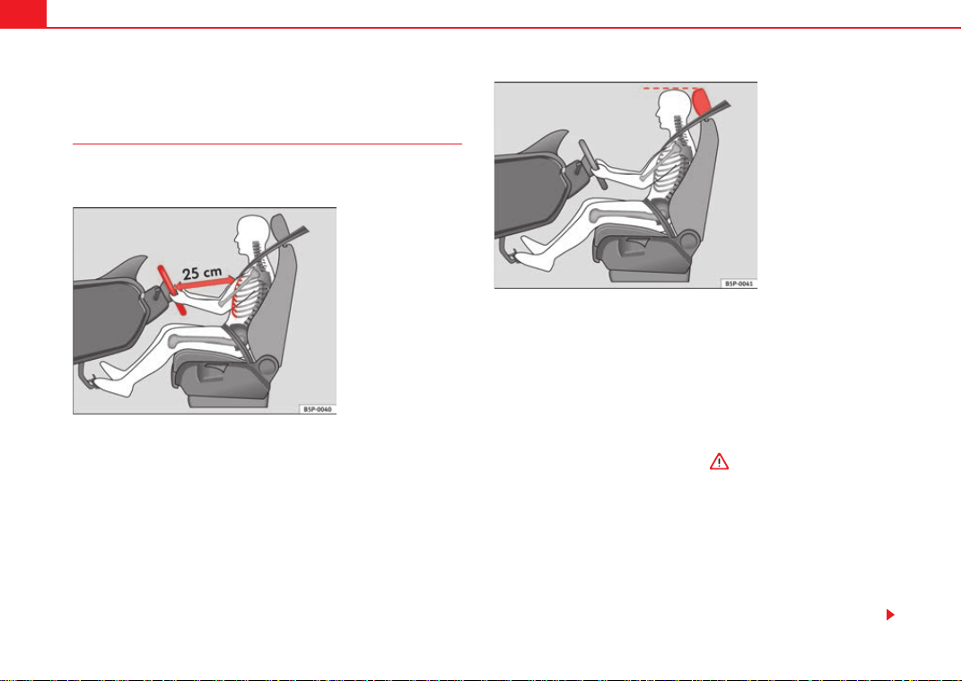
– Adjust the steering wheel so that there is a distance of at least 25
cm between the steering wheel and the centre of your chest
⇒ fig. 1.
– Move the driver seat forwards or backwards so that you are able
to press the accelerator, brake and clutch pedals to the floor with
your knees still slightly angled ⇒ .
– Ensure that you can reach the highest point of the steering
wheel.
– Adjust the head restraint so that its upper edge is at the same
level as the top of your head, or as close as possible to the same
level as the top of your head ⇒ fig. 2.
– Move the backrest to an upright position so that your backrests
completely against it.
Fig. 1 The proper
distance between driver
and steering wheel
Fig. 2 Proper head
restraint position for
driver
ExeoST_EN.book Seite 10 Freitag, 3. September 2010 11:41 11
Safe driving 11
Safety First Operating Instructions Practical Tips Technical Specifications
– Fasten your seat belt securely ⇒ page 18.
– Keep both feet in the footwell so that you have the vehicle under
control at all times.
Adjustment of the driver seat ⇒ page 134.
WARNING
• An incorrect sitting position of the driver can lead to severe injuries.
• Adjust the driver seat so that there is at least 25 cm distance between
the centre of the chest and the centre of the steering wheel ⇒ page 10,
fig. 1. If you are sitting closer than 25 cm, the airbag system cannot protect
you properly.
• If your physical constitution prevents you from maintaining the
minimum distance of 25 cm, contact a specialised workshop. The work-
shop will help you decide if special specific modifications are necessary.
• When driving, always hold the steering wheel with both hands on the
outside of the ring at the 9 o'clock and 3 o'clock positions. This reduces the
risk of injury when the driver airbag is triggered.
• Never hold the steering wheel at the 12 o'clock position, or in any other
manner (e.g. in the centre of the steering wheel). In such cases, if the
airbag is triggered, you may sustain injuries to the arms, hands and head.
• To reduce the risk of injury to the driver during sudden braking manoeu-
vres or an accident, never drive with the backrest tilted far back! The airbag
system and seat belts can only provide optimal protection when the back-
rest is in an upright position and the driver is wearing his or her seat belt
properly. The further the backrests are tilted to the rear, the greater the risk
of injury due to incorrect positioning of the belt web or to the incorrect
sitting position!
• Adjust the head restraint properly to achieve optimal protection.
Proper sitting position for front passenger
The front passenger must sit at least 25 cm away from the
dash panel so that the airbag can provide the greatest
possible protection in the event that it is triggered.
For your own safety and to reduce the risk of injury in the event of an
accident, we recommend the following adjustments for the front
passenger:
– Move the front passenger seat back as far as possible ⇒ .
– Move the backrest to an upright position so that your backrests
completely against it.
– Adjust the head restraint so that its upper edge is at the same
level as the top of your head, or as close as possible to the same
level as the top of your head ⇒ page 13.
– Keep both feet in the footwell in front of the front passenger seat.
– Fasten your seat belt securely ⇒ page 18.
It is possible to deactivate the passenger airbag in exceptional circum-
stances ⇒ page 23.
Adjusting the front passenger seat ⇒ page 134.
WARNING
• An incorrect sitting position of the front passenger can lead to severe
injuries.
• Adjust the front passenger seat so that there is at least 25 cm between
your chest and the dash panel. If you are sitting closer than 25 cm, the
airbag system cannot protect you properly.
ExeoST_EN.book Seite 11 Freitag, 3. September 2010 11:41 11
Safe driving12
• If your physical constitution prevents you from maintaining the
minimum distance of 25 cm, contact a specialised workshop. The work-
shop will help you decide if special specific modifications are necessary.
• Always keep your feet in the footwell when the vehicle is moving; never
rest them on the dash panel, out the window or on the seat. An incorrect
sitting position exposes you to an increased risk of injury in case of a
sudden braking or an accident. If the airbag is triggered, you could sustain
severe injuries due to an incorrect sitting position.
• To reduce the risk of injury to the front passenger in events such sudden
braking manoeuvres or an accident, never travel with the backrest tilted far
back! The airbag system and seat belts can only provide optimal protection
when the backrest is in an upright position and the front passenger is
wearing his or her seat belt properly. The further the backrests are tilted to
the rear, the greater the risk of injury due to incorrect positioning of the
belt web or to the incorrect sitting position!
• Adjust the head restraint properly in order to achieve maximum
protection.
Correct sitting position for passengers in the rear seats
Passengers in the rear seats must sit up straight, keep their
feet on the footwells, have the head restraints positioned for
use and wear their seat belts properly.
To reduce the risk of injury in the event of a sudden braking
manoeuvre or an accident, passengers on the rear bench seat must
consider the following:
– Adjust the head restraint to the correct position ⇒ page 14.
– Keep both feet in the footwell in front of the rear seat.
–Fasten your seat belt securely ⇒ page 18.
– Use an appropriate child restraint system when you take children
in the vehicle ⇒ page 46.
WARNING
• If the passengers on the rear seat are not sitting properly, they could
sustain severe injuries.
• Adjust the head restraint properly in order to achieve maximum protec-
tion.
• Seat belts can only provide optimal protection when backrests are in an
upright position and the passengers are wearing their seat belts properly.
If passengers on the rear seat are not sitting in an upright position, the risk
of injury due to incorrect positioning of the seat belt increases.
WARNING (continued)
ExeoST_EN.book Seite 12 Freitag, 3. September 2010 11:41 11
Safe driving 13
Safety First Operating Instructions Practical Tips Technical Specifications
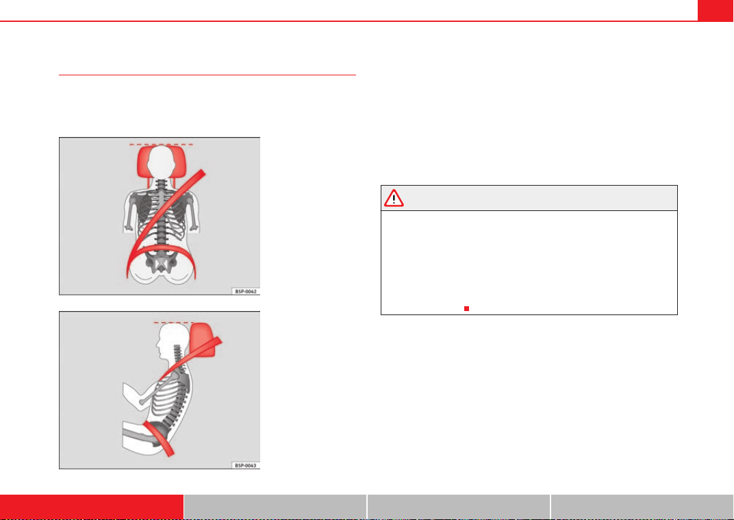
Correct adjustment of front seat head restraints
Properly adjusted head restraints are an important part of
passenger protection and can reduce the risk of injuries in
most accident situations.
Adjust the head restraint properly in order to achieve maximum
protection.
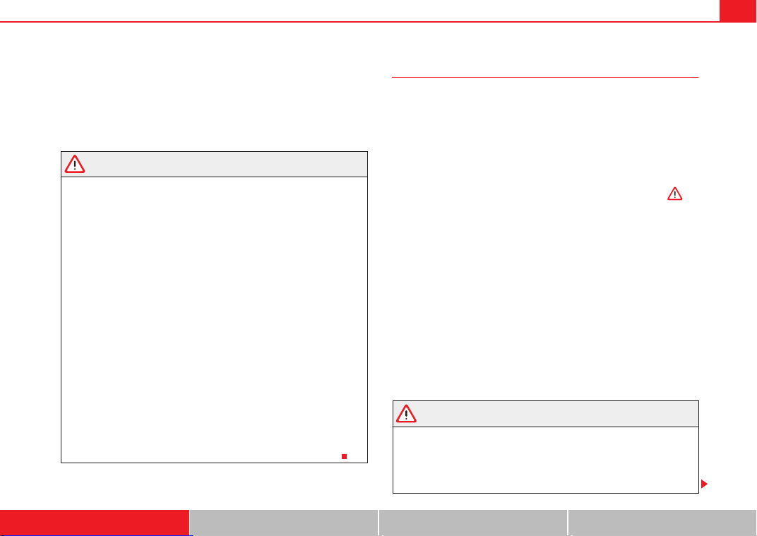
– Adjust the head restraint so that its upper edge is at the same
level as the top of your head or as close as possible to the same
level as the top of your head and, at the very least, at eye level
⇒ fig. 3 and ⇒ fig. 4
Adjusting the head restraints ⇒ page 134.
WARNING
• Travelling with the head restraints removed or improperly adjusted
increases the risk of severe injuries.
• Incorrectly adjusted head restraints could result in death in the event of
a collision or accident.
• Incorrectly adjusted head restraints also increase the risk of injury
during sudden or unexpected driving or braking manoeuvres.
• The head restraints must always be adjusted according to the
passenger's height.
Fig. 3 Properly adjusted
head restraint viewed
from the front
Fig. 4 Properly adjusted
head restraint viewed
from the side
ExeoST_EN.book Seite 13 Freitag, 3. September 2010 11:41 11
Safe driving14
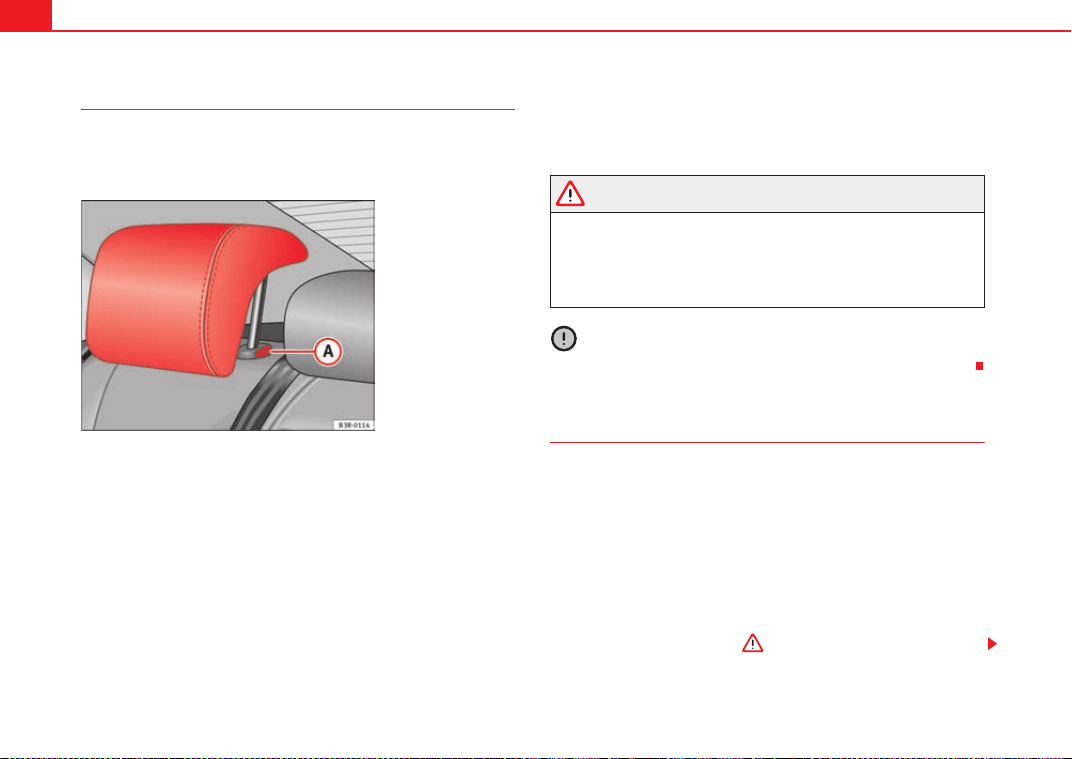
Correct adjustment of rear seat head restraints
Properly adjusted head restraints are an important part of the
passenger protection and can reduce the risk of injuries in
most accident situations
Raising the head restraint
– Take hold of the sides of the head restraint with both hands.
– Pull the head restraint up as far as it will go.
Lowering the head restraint
–Press button ⇒ fig. 5 and lower the head restraint.
Removing the head restraint
– Pull the head restraint up as far as it will go.
–Press button ⇒ fig. 5 and pull out the head restraint.
Fitting the head restraint
– Insert the head restraint in its guides until it clicks into place.
Press button and lower the head restraint.
WARNING
• Under no circumstances should the rear passengers travel while the
head restraints are in the non-use position.
• Do not swap the centre rear head restraint with either of the outer seat
rear head restraints.
• Risk of injury in case of an accident!
Caution
Note the instructions on the adjustment of the head restraints ⇒ page 13.
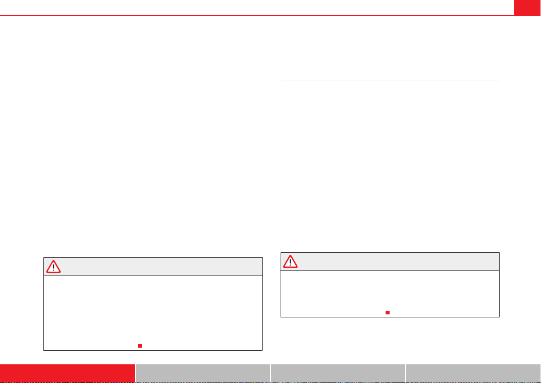
Examples of incorrect sitting positions
An incorrect sitting position can lead to severe injuries to
occupants.
Seat belts can provide optimal protection only when the belt webs
are properly positioned. Incorrect sitting positions substantially
reduce the protective function of seat belts and increase the risk of
injury due to incorrect seat belt position. As the driver, you are
responsible for all vehicle occupants, especially children.
– Never allow anyone to assume an incorrect sitting position in the
vehicle while travelling ⇒ .
Fig. 5 Outer rear seats:
Head restraints
A
A
A
A
A
A
ExeoST_EN.book Seite 14 Freitag, 3. September 2010 11:41 11
Safe driving 15
Safety First Operating Instructions Practical Tips Technical Specifications
The following list contains examples of sitting positions that could be
dangerous for all occupants. The list is not complete, but we would like to
make you aware of this issue.
Therefore, whenever the vehicle is in motion:
• Never stand in the vehicle,
• never stand on the seats,
• never kneel on the seats,
• never tilt your backrest far to the rear,
• never lean against the dash panel,
• never lie on the rear bench,
• never sit on the front edge of a seat,
• never sit sideways,
• never lean out of a window,
• never put your feet out of a window,
• never put your feet on the dash panel,
• never put your feet on the surface of a seat,
• do not allow anyone to travel in the footwell,
• never travel without wearing the seat belt,
• do not allow anyone to travel in the luggage compartment.
WARNING
• Any incorrect sitting position increases the risk of severe injuries.
• Sitting in an incorrect position exposes the occupants to severe injuries
if airbags are triggered, by striking a passenger who has assumed an incor-
rect sitting position.
• Before the vehicle moves, assume the proper sitting position and main-
tain it throughout the trip. Before every trip, instruct your passengers to sit
properly and to stay in this position during the trip ⇒ page 10, “Proper
sitting position for occupants”.
Pedal area
Pedals
The operation of all pedals must never be impaired by objects
or floor mats.
– Ensure that you can always press the accelerator, brake and
clutch pedals unimpaired to the floor.
– Ensure that the pedals can return unimpaired to their initial posi-
tions.
Use only floor mats which leave the pedal area free and can be securely
fastened on the footwell.
If a brake circuit fails, the brake pedal must be pressed down thoroughly in
order to stop the vehicle.
Wearing suitable shoes
Always wear shoes which support your feet properly and give you a good
feeling for the pedals.
WARNING
• Restricting pedal operation can lead to critical situations while driving.
• Never place objects on the driver footwell. An object could move into
the pedal area and impair pedal operation. In the event of a sudden driving
or braking manoeuvre, you will not be able to operate the brake, clutch or
accelerator pedal. Risk of accident!
ExeoST_EN.book Seite 15 Freitag, 3. September 2010 11:41 11
Safe driving16
Floor mats on the driver side
Only floor mats may be used which can be securely fastened
in the footwell and do not impair operation of the pedals.
– Ensure that the floor mats are securely fastened during the trip
and do not obstruct the pedals ⇒ .
Only use floor mats which leave the pedals clear and which are secured to
prevent them from slipping. You can obtain suitable floor mats from a special-
ised dealership.
WARNING
• If the pedals are obstructed, an accident may occur. Risk of serious inju-
ries.
• Ensure that the floor mats are always securely attached.
• Never lay or fit floor mats or other floor coverings over the original floor
mats. This would reduce the pedal area and could obstruct the pedals. Risk
of accident.
Storing objects
Loading the luggage compartment
All luggage and other loose objects must be safely secured in
the luggage compartment.
Unsecured objects which shift back and forth could impair the
driving safety or driving characteristics of the vehicle by shifting the
centre of gravity.
– Distribute the load evenly in the luggage compartment.
– Lay and stow heavy luggage as far forward as possible in the
luggage compartment.
– Stow heavy luggage as low as possible in the luggage compart-
ment.
– Secure heavy objects to the fitted fastening rings ⇒ page 17.
WARNING
• Loose luggage and other objects in the luggage compartment could
cause serious injuries.
• Always stow objects in the luggage compartment and secure them on
the fastening rings.
• Use suitable straps to secure heavy objects.
• During sudden manoeuvres or accidents, loose objects can be thrown
forward, injuring vehicle occupants or passers-by. This increased risk of
injury will be further increased if a loose object is struck by an inflating
airbag. If this happens, objects can be transformed into “missiles”. Risk of
fatal injury.
• Please note that the centre of gravity may shift when transporting
heavy objects; this may affect the vehicle's handling and lead to an acci-
dent. Therefore, it is essential to adjust your speed and driving style
accordingly, to avoid accidents.
• Never exceed the allowed axle weights or allowed maximum weight. If
the allowed axle load or the allowed total weight is exceeded, the driving
characteristics of the vehicle may change, leading to accidents, injuries
and damage to the vehicle.
• Never leave your vehicle unattended, especially when the tailgate is
open. Children could climb into the luggage compartment, closing the door
behind them; they will be trapped and run the risk of death.
ExeoST_EN.book Seite 16 Freitag, 3. September 2010 11:41 11
Safe driving 17
Safety First Operating Instructions Practical Tips Technical Specifications
• Never allow children to play in or around the vehicle. Close and lock all
the doors and tailgate when you leave the vehicle. Before you lock the
vehicle, make sure that there are no adults or children in the vehicle.
• Never transport passengers in the luggage compartment. All passen-
gers must have their seat belt fastened ⇒ page 18.
Note
• Air circulation in the vehicle helps reduce fogging of the windows. Used
air escapes through ventilation slits in the side trim of the luggage compart-
ment. Ensure that the ventilation slits are never covered.
• Straps for securing the load to the fastening rings are commercially
available.
Fastening rings
There can be four fastening rings in the luggage compart-
ment for fastening luggage and other objects.
– Always use suitable and undamaged straps to secure luggage
and other objects to the fastening rings ⇒ in “Loading the
luggage compartment” on page 16.
– Pull up the fastening rings to attach the straps.
During a collision or an accident, even small and light objects can build up so
much energy that they can cause very severe injuries. The amount of kinetic
energy depends on the speed of the vehicle and the weight of the object. The
most significant factor, however, is the speed of the vehicle.
Example: An object weighing 4.5 kg is lying unsecured in the vehicle. During
a frontal collision at a speed of 50 km/h, this object generates a force corre-
sponding to 20 times its weight. That means that the effective weight of the
object increases to about 90 kg. You can imagine the severity of the injuries
which might be sustained if this object strikes an occupant as it flies through
the passenger compartment. This increased risk of injury will be further
increased if a loose object is struck by an inflating airbag.
WARNING
• If pieces of luggage or other objects are secured to the fastening rings
with inappropriate or damaged retaining cords, injuries could be sustained
in the event of braking manoeuvres or accidents.
• To prevent pieces of luggage or other objects from flying forward,
always use appropriate retaining cords which are secured to the fastening
rings.
• Never secure a child seat on the fastening rings.
WARNING (continued)
ExeoST_EN.book Seite 17 Freitag, 3. September 2010 11:41 11
Seat belts18
Seat belts
Brief introduction
Before driving: remember your seat belt!
Wearing a seat belt properly can save your life!
In this chapter you will learn the importance of wearing seat belts,
how they work and how to properly fasten, adjust and wear them.
– Read and consider all the information as well as the warnings in
this chapter.
WARNING
• If seat belts are worn incorrectly or not at all, the risk of severe injuries
increases.
• Properly worn seat belts can reduce severe injuries in case of sudden
braking manoeuvres or accidents. For safety reasons, you and your passen-
gers must always wear the seat belts properly while the vehicle is moving.
• Pregnant women or people with physical disabilities must also use seat
belts. Like all other passengers, these people can also sustain severe inju-
ries if they are not wearing their seat belts properly.
Number of seats
Your vehicle has five seats, two in the front and three in the rear. Each seat is
equipped with a three-point seat belt.
In some versions, your vehicle is approved only for four seats. Two front seats
and two rear seats.
WARNING
• More people than available seats must never be transported in your
vehicle.
• Every passenger in the vehicle must properly fasten and wear the seat
belt belonging to his or her seat. Children must be protected with an appro-
priate child restraint system.
Seat belt warning lamp*
The warning lamp acts as a reminder to the driver to fasten
the seat belt.
Before starting the vehicle:
–Fasten your seat belt securely.
– Instruct your passengers to fasten their seat belts properly before
driving off.
– Protect children by using a child seat according to the child's
height and weight.
After switching on the ignition, the warning lamp will remain lit until the
driver and front passenger (if applicable) have fastened their seat belts.
When the vehicle has reached a certain speed, you will also hear a warning
signal and the warning light will flash.
ExeoST_EN.book Seite 18 Freitag, 3. September 2010 11:41 11
Seat belts 19
Safety First Operating Instructions Practical Tips Technical Specifications
Why wear seat belts?
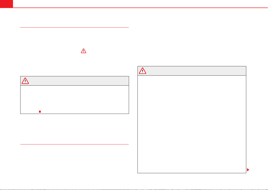
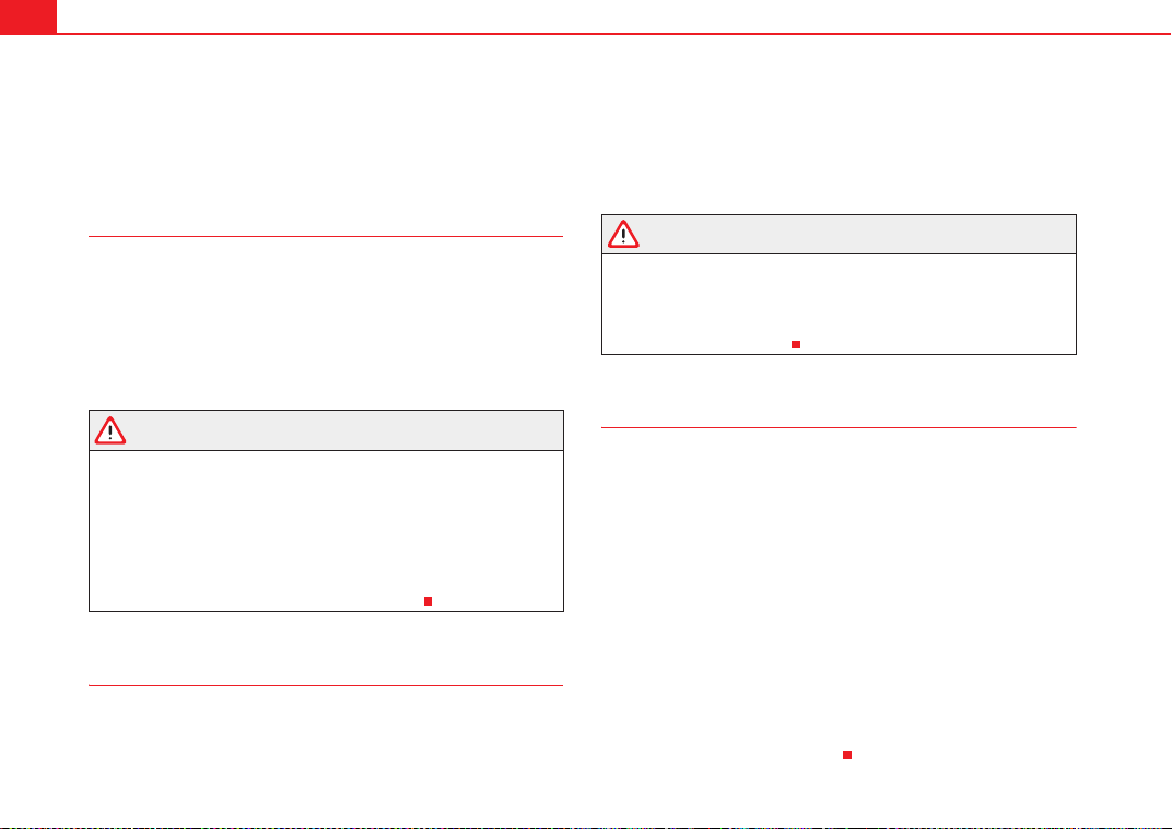
Physical principles of frontal collisions
In the event of a frontal collision, a large amount of kinetic
energy must be absorbed.
It is easy to explain how the laws of physics work in the case of a head-on
collision: When a vehicle starts moving ⇒ fig. 6, a certain amount of energy
known as kinetic energy is produced in the vehicle and its occupants.
The amount of kinetic energy depends on the speed of the vehicle and the
weight of the vehicle and its passengers. The higher the speed and the
greater the weight, the more energy there is to be released in an accident.
The most significant factor, however, is the speed of the vehicle. If the speed
doubles from 25 km/h to 50 km/h, for example, the kinetic energy is multi-
plied by four.
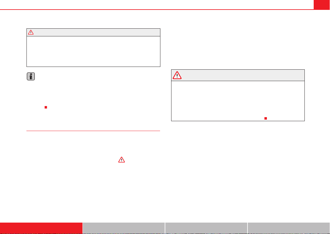
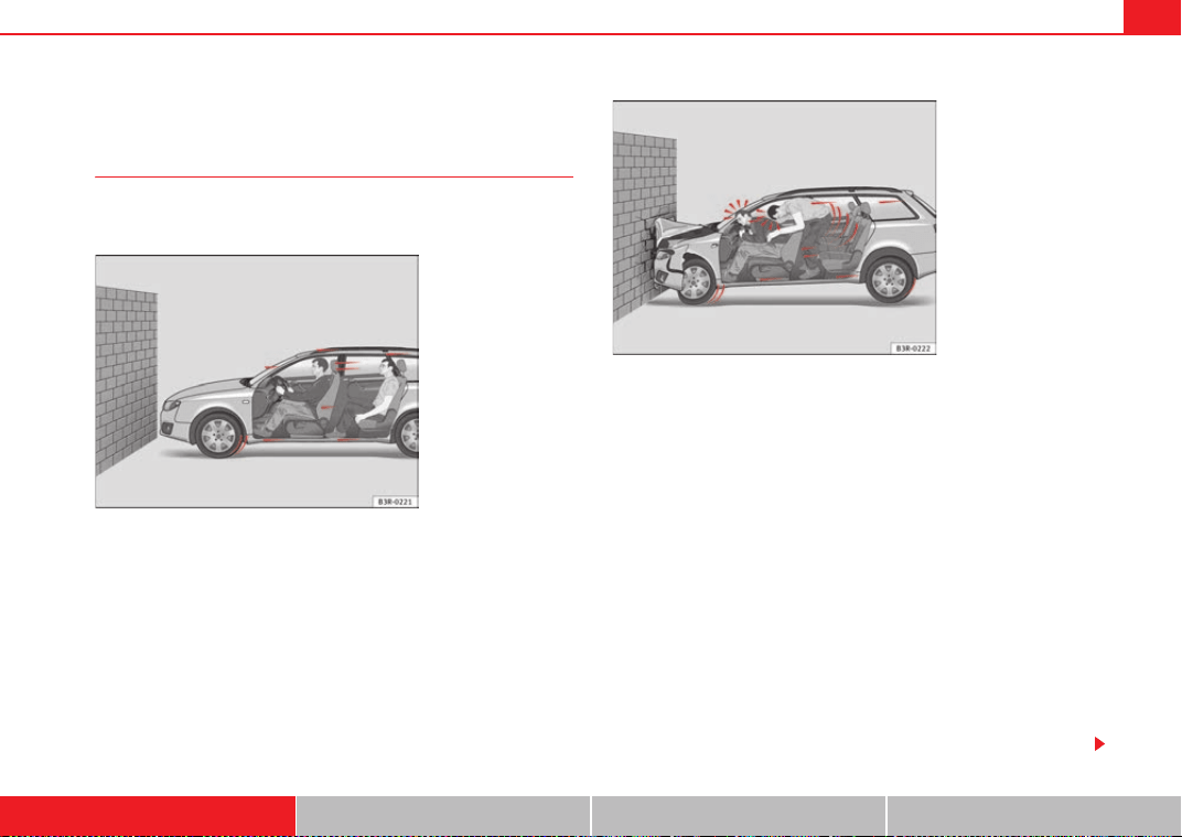
Because the passengers in our example are not restrained by seat belts, in
the case of a head-on collision all of their kinetic energy has to be absorbed
at the point of impact ⇒ fig. 7.
Even at speeds of 30 km/h to 50 km/h, the forces acting on bodies in a colli-
sion can easily exceed one tonne (1000 kg). At greater speed these forces are
even higher.
Passengers not wearing seat belts are not “attached” to the vehicle. In a
head-on collision, they will move forward at the same speed their vehicle was
Fig. 6 Vehicle about to hit
a wall: the occupants are
not wearing seat belts
Fig. 7 The vehicle hits
the wall: the occupants
are not wearing seat belts
ExeoST_EN.book Seite 19 Freitag, 3. September 2010 11:41 11
Seat belts20
travelling just before the impact. This example applies not only to head-on
collisions, but to all accidents and collisions.
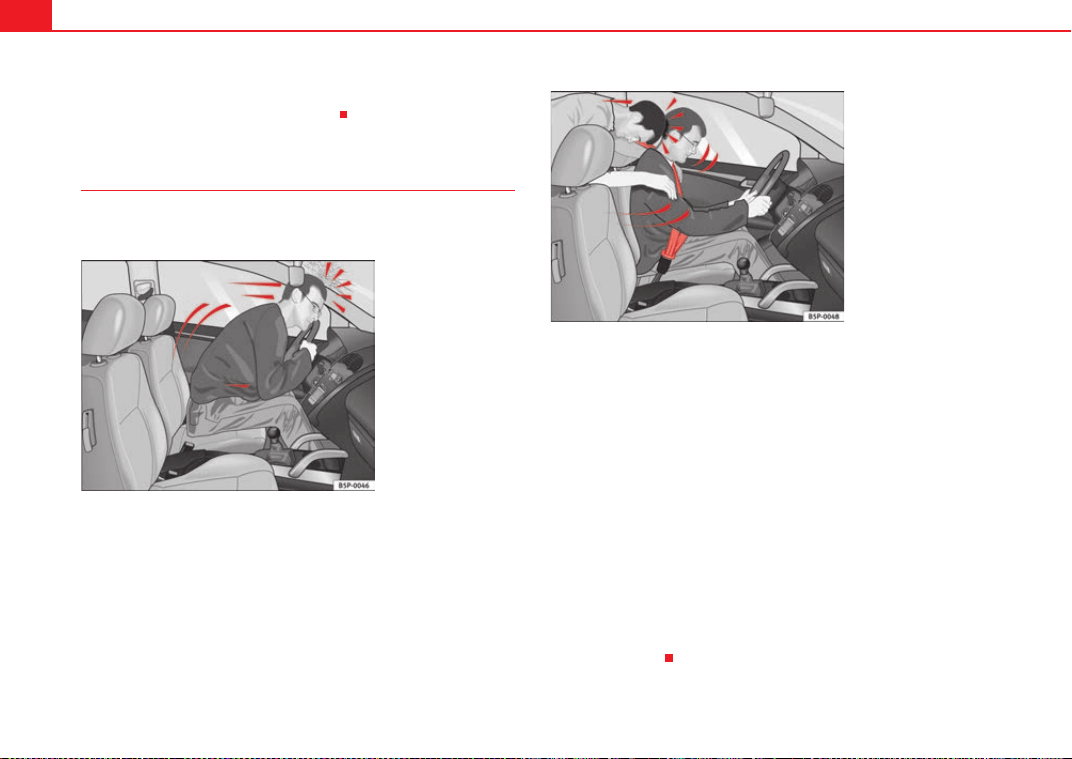
The danger of not using the seat belt
The general belief that the passengers can protect them-
selves with their hands in a minor collision is false.
Even at low speeds the forces acting on the body in a collision are so great
that it is not possible to brace oneself with one's hands. In a frontal collision,
unbelted passengers are thrown forward and will make violent contact with
the steering wheel, dash panel, windscreen or whatever else is in the way
⇒ fig. 8.
The airbag system is not a substitute for seat belts. When triggered, airbags
provide only additional protection. All occupants (including the driver) must
wear seat belts properly during the trip. This will reduce the risk of severe
injuries in the event of an accident – regardless of whether an airbag is fitted
for the seat or not.
Note that airbags can be triggered only once. To achieve the best possible
protection, the seat belt must always be worn properly so that you will be
protected in accidents in which no airbag is deployed.
It is also important for the rear passengers to wear seat belts properly, as they
could otherwise be thrown forward violently in an accident. Rear passengers
who do not use seat belts endanger not only themselves but also the front
occupants ⇒ fig. 9.
Fig. 8 A driver not
wearing a seat belt is
thrown forward violently.
Fig. 9 The unbelted rear
passenger is thrown
forward violently, hitting
the driver wearing a seat
belt.
ExeoST_EN.book Seite 20 Freitag, 3. September 2010 11:41 11
Seat belts 21
Safety First Operating Instructions Practical Tips Technical Specifications
Seat belt protection
Passengers not wearing seat belts risk severe injuries in the
event of an accident.
Properly worn seat belts hold the vehicle occupants in the correct sitting posi-
tions and substantially reduce the kinetic energy in the event of an accident.
Seat belts also help to prevent uncontrolled movements that could lead to
severe injuries. In addition, properly worn seat belts reduce the danger of
being thrown from the vehicle.
Passengers wearing their seat belts correctly benefit greatly from the ability
of the belts to absorb kinetic energy. The front part of your vehicle and other
passive safety features (such as the airbag system) are also designed to
absorb the kinetic energy released in a collision. Taken together, all these
features reduce the releasing kinetic energy and consequently, the risk of
injury.
Our examples describe frontal collisions. Of course, properly worn seat belts
substantially reduce the risk of injury in all other types of accidents. This is
why it is so important to fasten seat belts before every trip, even when "just
driving around the corner".
Ensure that your passengers wear their seat belts as well. Accident statistics
have shown that wearing seat belts is an effective means of substantially
reducing the risk of injury and improving the chances of survival in a serious
accident. Furthermore, properly worn seat belts improve the protection
provided by airbags in the event of an accident. For this reason, wearing a
seat belt is required by law in most countries.
Although your vehicle is equipped with airbags, the seat belts must be
fastened and worn. The front airbags, for example, are only triggered in some
frontal accidents. The front airbags will not be triggered during minor frontal
collisions, minor side collisions, rear collisions, overturns or accidents in
which the airbag trigger threshold value in the control unit is not exceeded.
Therefore, you should always wear your seat belt and ensure that your
passengers have fastened their seat belts properly before you drive off!
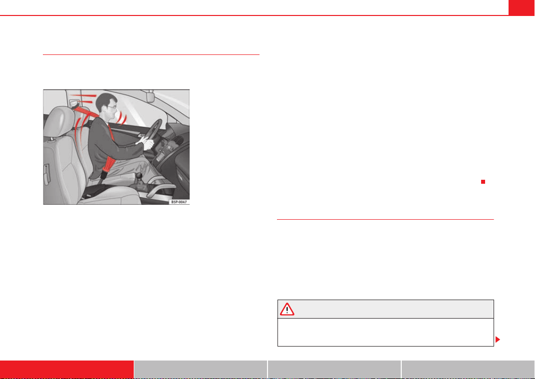
Safety instructions on using seat belts
If seat belts are used correctly, they can reduce the risk of
injury in an accident.
– Always wear the seat belt as described in this section.
– Ensure that the seat belts can be fastened at all times and are not
damaged.
WARNING
• If the seat belts are worn incorrectly or not at all, the risk of severe inju-
ries increases. The optimal protection from seat belts can be achieved only
if you use them properly.
Fig. 10 A driver wearing
the seat belt properly is
secured by the belt in
sharp braking
ExeoST_EN.book Seite 21 Freitag, 3. September 2010 11:41 11
Seat belts22
• Fasten your seat belt before every trip - even when driving in town. The
other passengers must also wear the seat belts at all times, otherwise they
run the risk of being injured.
• The seat belt cannot offer its full protection if the seat belt is not posi-
tioned correctly.
• Never allow two passengers (even children) to share the same seat belt.
• Keep both feet in the footwell in front of your seat as long as the vehicle
is in motion.
• Never unbuckle a seat belt while the vehicle is in motion. Risk of fatal
injury.
• The seat belt must never be twisted while it is being worn.
• The seat belt should never lie on hard or fragile objects (such as glasses
or pens, etc.) because this can cause injuries.
• Do not allow the seat belt to be damaged or jammed, or to rub on any
sharp edges.
• Never wear the seat belt under the arm or in any other incorrect posi-
tion.
• Loose, bulky clothing (such as an overcoat over a jacket) impairs the
proper fit and function of the belts, reducing their capacity to protect.
• The slot in the seat belt buckle must not be blocked with paper or other
objects, as this can prevent the latch plate from engaging securely.
• Never use seat belt clips, retaining rings or similar instruments to alter
the position of the belt webbing.
• Frayed or torn seat belts or damage to the connections, belt retractors
or parts of the buckle could cause severe injuries in the event of an acci-
dent. Therefore, you must check the condition of all seat belts at regular
intervals.
• Seat belts which have been worn in an accident and stretched must be
replaced by a qualified workshop. Renewal may be necessary even if there
is no apparent damage. The belt anchorage should also be checked.
• Do not attempt to repair a damaged seat belt yourself. The seat belts
must not be removed or modified in any way.
• The belts must be kept clean, otherwise the retractors may not work
properly ⇒ page 221.
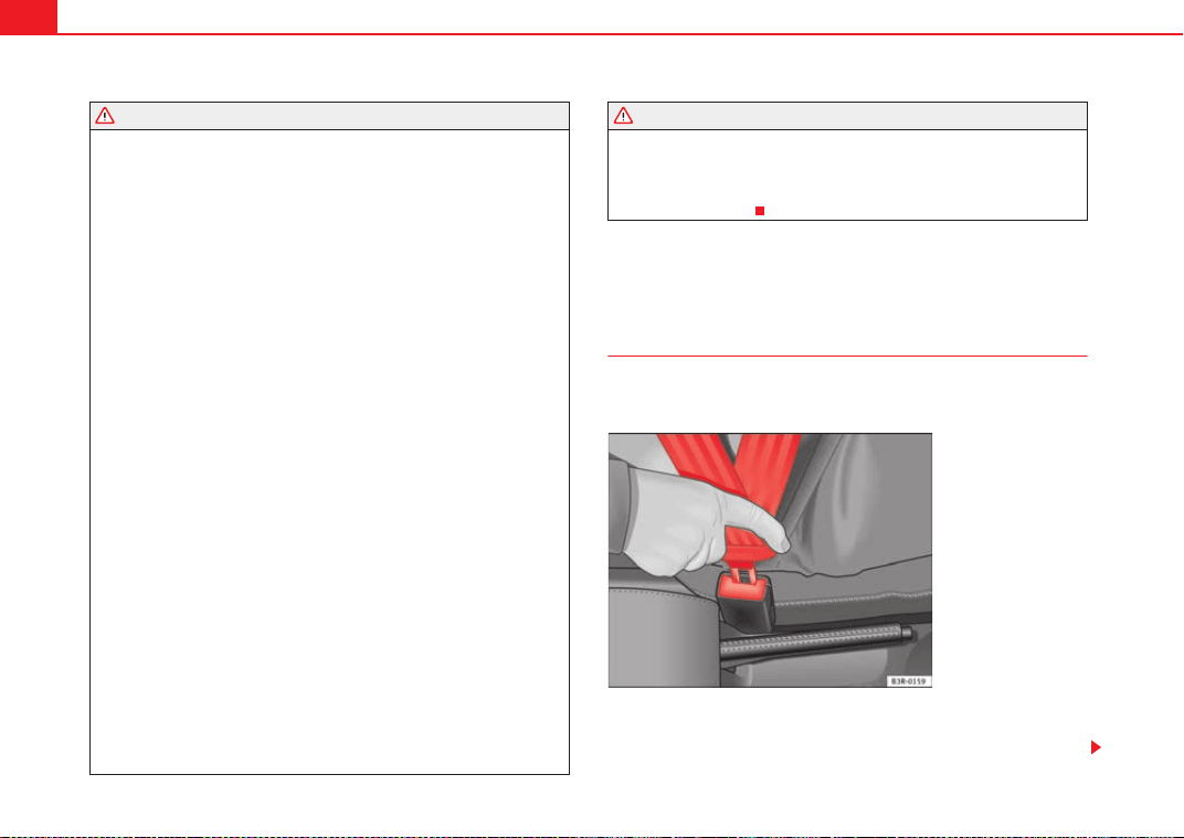
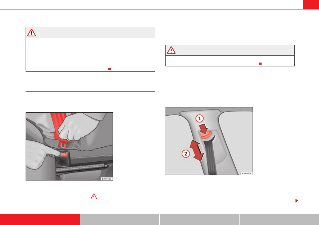
Seat belts
Seat belt adjustment
The seat belts for the front and rear occupants are locked into
position by a latch.
The seat belt cannot offer its full protection if the seat belt is not
positioned correctly.
WARNING (continued) WARNING (continued)
Fig. 11 Belt buckle and
latch plate of seat belt
ExeoST_EN.book Seite 22 Freitag, 3. September 2010 11:41 11
Seat belts 23
Safety First Operating Instructions Practical Tips Technical Specifications
– Adjust the seat and head restraint correctly.
– To fasten the belt, take hold of the latch plate and pull it slowly
across your chest and lap.
– Insert the latch into the buckle for the appropriate seat and push
it down until it is securely locked with a click ⇒ page 22, fig. 11.
– Pull the belt to ensure that the latch plate is securely engaged in
the buckle.
The seat belts are equipped with an automatic retractor on the shoulder
strap. Full freedom of movement is permitted when the shoulder belt is pulled
slowly. However, during sudden braking, during travel in steep areas or
bends and during acceleration, the automatic retractor on the shoulder belt
is locked.
The automatic belt retractors on the front seats are fitted with seat belt
tensioners ⇒ page 26.
WARNING
• An incorrectly worn seat belt can cause severe injuries in the event of
an accident.
• The seat belts offer best protection only when the backrests are in an
upright position and the seat belts have been fastened properly.
• Never put the latch plate in the buckle of another seat. If you do this, the
seat belt will not protect you properly and the risk of injury is increased.
• If an occupant is incorrectly belted in, the belt cannot protect him or her
properly. An incorrectly positioned seat belt can cause extremely severe
injuries.
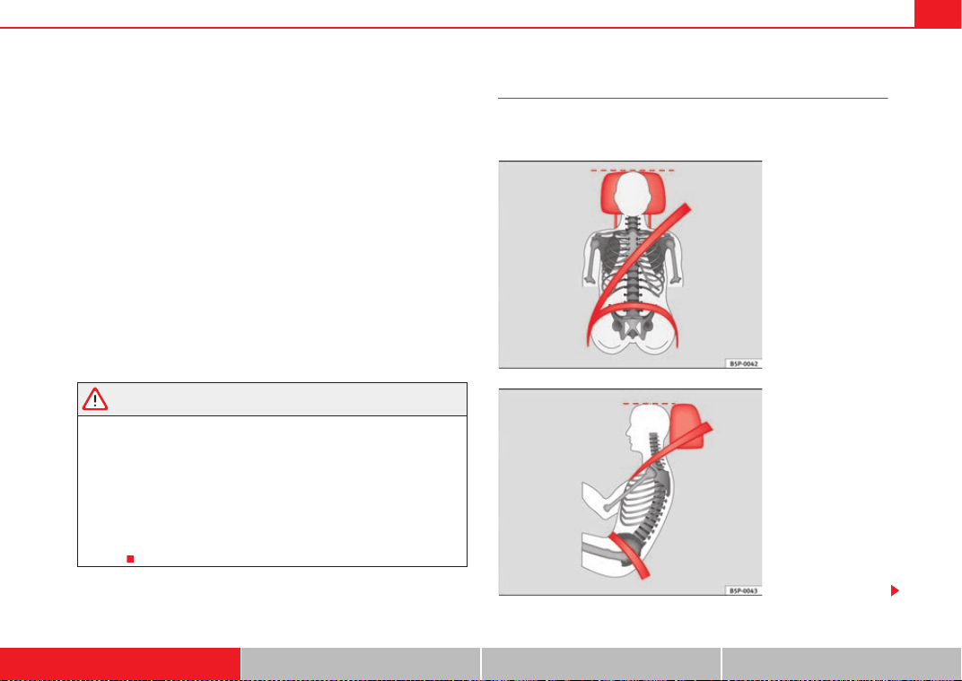
Seat belt position
Seat belts offer their maximum protection only when they are
properly positioned.
Fig. 12 Correct seat belt
and head restraint posi-
tions, viewed from front
Fig. 13 Correct seat belt
and head restraint posi-
tions, viewed from side
ExeoST_EN.book Seite 23 Freitag, 3. September 2010 11:41 11
Seat belts24
The following features are available to adjust the seat belt in the shoulder
region:
• belt height adjustment for the front seats.
• front seat height adjustment*.
WARNING
• An incorrectly worn seat belt can cause severe injuries in the event of
an accident.
• The shoulder part of the seat belt must lie on the centre of the shoulder,
never across the neck. The seat belt must lie flat and snugly on the torso
⇒ page 23, fig. 12.
• The lap part of the seat belt must lie across the pelvis, never across the
stomach. The seat belt must lie flat and snugly on the pelvis ⇒ page 23,
fig. 13. Pull the belt tight if necessary to take up any slack.
• Read and observe the warnings ⇒ page 21.
Pregnant women must also fasten their seat belts properly
The best protection for the unborn child is for the mother to
wear the seat belt properly at all times during the pregnancy.
The seat belt provides maximum protection only when the seat belt
is properly positioned ⇒ page 23.
– Adjust the front seat and head restraint correctly ⇒ page 10.
– Holding the latch plate, pull the belt evenly across your chest and
as low as possible over the pelvis ⇒ fig. 14.
– Insert the latch plate into the buckle for the appropriate seat and
push it down until it is securely locked with a click ⇒ .
– Pull the belt to ensure that the latch plate is securely engaged in
the buckle.
Fig. 14 Positioning seat
belts during pregnancy
ExeoST_EN.book Seite 24 Freitag, 3. September 2010 11:41 11
Seat belts 25
Safety First Operating Instructions Practical Tips Technical Specifications
WARNING
• An incorrectly worn seat belt can cause severe injuries in the event of
an accident.
• For pregnant women, the lap part of the seat belt must lie as low as
possible over the pelvis, never across the stomach, and always lie flat so
that no pressure is exerted on the abdomen.
• Read and observe the warnings ⇒ page 21.
Seat belt release
The seat belt must not be unfastened until the vehicle has
come to a standstill.
– Press the red button on the belt buckle ⇒ fig. 15. The latch plate
is released and springs out ⇒ .
– Guide the belt back by hand so that it rolls up easily and the trim
is not damaged
WARNING
Never unbuckle a seat belt while the vehicle is in motion. If you do, you
increase the risk of sustaining severe or fatal injuries.
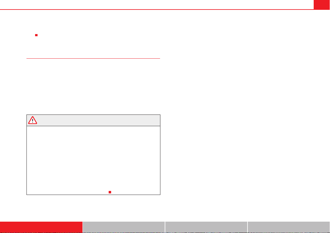
Seat belt height adjustment
Seat belt height adjusters can be used to adjust the height of
the shoulder area of the seat belt.
The belt height adjuster can be lowered by keeping the button
pressed down at the same time.
– Press button ⇒ fig. 16 to adjust the belt height.
Fig. 15 Removing latch
plate from buckle
Fig. 16 Belt height
adjuster
A
1
ExeoST_EN.book Seite 25 Freitag, 3. September 2010 11:41 11
Seat belts26
– Take hold of the top guide fitting and slide it up or down so that
the shoulder part of the seat belt is positioned roughly midway
over the shoulder, although it must never rest against the neck
⇒ page 25, fig. 16 ⇒ in “Seat belt position” on page 23.
– After adjusting, pull the belt sharply to check that the catch on
the guide fitting is engaged securely.
Note
It is also possible to adjust the height of the front seats to obtain the best
position for the front seat belts.
Incorrectly fastened seat belts
Incorrectly worn seat belts can cause severe or even mortal
injuries.
Seat belts can provide optimal protection only if the belt web is
properly worn. The seat belts must be fastened exactly in the order
described in this chapter. An incorrect sitting position impairs
substantially the protection a seat belt offers and can lead to severe
or fatal injuries. The risk of severe or fatal injuries is especially
increased when a deploying airbag strikes an occupant who has
assumed an incorrect sitting position. As the driver, you are respon-
sible for all vehicle occupants, especially children. Therefore:
– Never allow anyone to wear the seat belt incorrectly while the
vehicle is moving ⇒ .
WARNING
• An incorrectly worn seat belt increases the risk of severe injuries.
• Before every trip, instruct your passengers to adjust their seat belts
properly and to wear them for the whole journey.
• Read and always observe information and warnings concerning the use
of seat belts ⇒ page 21.
Seat belt tensioners
Function of the seat belt tensioner
During a frontal collision, the seat belts on the front seats are
retracted automatically.
The seat belts for the front occupants are equipped with belt tensioners.
Sensors will trigger the belt tensioners during severe head-on, lateral and
rear collisions only if the seat belt is being worn. This retracts and tightens the
seat belts, reducing the forward motion of the occupants.
The seat belt tensioner can be triggered only once.
The seat belt tensioners will not be triggered in the event of a light frontal,
side or rear collision, if the vehicle overturns or in situations where no large
forces act on the front, side or rear of the vehicle.
Note
• If the seat belt tensioners are triggered, a fine dust is produced. This is
normal and it is not an indication of fire in the vehicle.
• The relevant safety requirements must be observed when the vehicle or
components of the system are scrapped. Specialised workshops are familiar
A
2
ExeoST_EN.book Seite 26 Freitag, 3. September 2010 11:41 11
Seat belts 27
Safety First Operating Instructions Practical Tips Technical Specifications
with these regulations and will be pleased to pass on the information to
you.
Service and disposal of belt tensioners
The belt tensioners are components of the seat belts that are installed in the
seats of your vehicle. If you work on the belt tensioners or remove and install
parts of the system when performing other repair work, the seat belt may be
damaged. The consequence may be that, in the event of an accident, the belt
tensioners function incorrectly or not at all.
So that the effectiveness of the seat belt tensioner is not reduced and that
removed parts do not cause any injuries or environmental pollution, regula-
tions, which are known to the specialised workshops, must be observed.
WARNING
• Improper use or repairs not carried out by qualified mechanics increase
the risk of severe or fatal injuries. The belt tensioners may fail to trigger or
may trigger in the wrong circumstances.
• Never attempt to repair, adjust, remove or install parts of the belt
tensioners or seat belts.
• The seat belt tensioner, seat belt and automatic retractor cannot be
repaired.
• Any work on the belt tensioners and seat belts, including the removal
and refitting of system parts in conjunction with other repair work, must be
performed by a qualified workshop only.
• The belt tensioners will only provide protection for one accident and
must be changed if they have been activated.
ExeoST_EN.book Seite 27 Freitag, 3. September 2010 11:41 11
Airbag system28
Airbag system
Brief introduction
Why wear a seat belt and assume the correct sitting
position?
For the inflating airbags to achieve the best protection, the
seat belt must always be worn properly and the correct sitting
position must be assumed.
For your own safety and the safety of the passengers, please ensure
the following before driving:
– Always wear the seat belt properly ⇒ page 18.
– Adjust the driver seat and the steering wheel correctly
⇒ page 10.
– Adjust the front passenger seat correctly ⇒ page 11.
– Adjust the head restraint correctly ⇒ page 13.
– Use the correct child restraint system to protect children in your
vehicle ⇒ page 46.
The airbag is deployed at high speed in fractions of a second. If you have an
incorrect seating position at the time the airbag is deployed, it could cause
you critical injuries. Therefore, it is essential that all passengers in the vehicle
assume a correct sitting position while travelling.
A sharp braking before an accident may cause a passenger not wearing a seat
belt to be thrown forward into the area of the deploying airbag. In this case,
the inflating airbag may inflict critical or fatal injuries on the occupant. This
also applies to children.
Always maintain the greatest possible distance between yourself and the
front airbag. This way, the front airbags can completely deploy when trig-
gered, providing their maximum protection.
The most important factors that will trigger an airbag are: the type of acci-
dent, the angle of collision and the speed of the vehicle.
Whether the airbags are triggered depends primarily on the vehicle deceler-
ation rate resulting from the collision and detected by the control unit. If the
vehicle deceleration occurring during the collision and measured by the
control unit remains below the specified reference values, the front, side
and/or curtain airbag will not be triggered. Take into account that the visible
damage in a vehicle involved in an accident, no matter how serious, is not a
determining factor for the airbags to have been triggered.
WARNING
• Wearing the seat belt incorrectly or assuming an incorrect sitting posi-
tion can lead to critical or fatal injuries.
• All occupants, including children, who are not properly belted can
sustain critical or fatal injuries if the airbag is triggered. Children up to 12
years old should always travel on the rear seat. Never transport children in
the vehicle if they are not restrained or the restraint system is not appro-
priate for their age, size or weight.
• If you are not wearing a seat belt, if you lean forward or to the side while
travelling or assume an incorrect sitting position, there is a substantially
increased risk of injury. This increased risk of injury will be further
increased if you are struck by an inflating airbag.
• To reduce the risk of injury from an inflating airbag, always wear the
seat belt properly ⇒ page 18.
ExeoST_EN.book Seite 28 Freitag, 3. September 2010 11:41 11
Airbag system 29
Safety First Operating Instructions Practical Tips Technical Specifications
• Always adjust the front seats properly.
The danger of fitting a child seat on the front passenger seat
Rear-facing child seats must never be used on the front
passenger seat when the front passenger airbag is enabled.
The front passenger airbag is a serious risk for a child if it is activated. The
front passenger seat is life threatening to a child if he/she is transported in a
rear-facing child seat. Children up to 12 years old should always travel on the
rear seat.
If a rear-facing child seat is secured to the front passenger seat, an inflating
airbag can strike it with such force that it can cause critical or fatal injuries.
Therefore we strongly recommend you to transport children on the rear seats.
That is the safest place for children in the vehicle. Alternatively, the front
passenger airbag can be disabled with a key-operated switch ⇒ page 44.
When transporting children, use a child seat appropriate to the age and size
of each child ⇒ page 46.
For those vehicles that do not include a key lock switch to disconnect the
airbag, the vehicle must be taken to a Technical Service.
WARNING
• If a child seat is secured to the front passenger seat, the risk to the child
of sustaining critical or fatal injuries in the event of an accident increases.
• Never secure a rear-facing child seat to the front passenger seat if the
front passenger airbag is enabled. The child can suffer critical or fatal inju-
ries if the front passenger airbag is triggered.
• An inflating front passenger airbag can strike the rear-facing child seat
and hurl it with great force against the door, the roof or the backrest.
• If, under special circumstances, it is necessary to transport a child in a
rear-facing child seat on the front passenger seat, it is absolutely essential
that you observe the following safety measures:
− Deactivate the front passenger airbag ⇒ page 44, “Deactivating
airbags”.
− The child seat must be approved by the child seat manufacturer for
use on a front passenger seat with front or side airbag.
− Follow the installation instructions given by the child seat manufac-
turer and observe the safety instructions ⇒ page 46, “Child safety”.
− Before properly installing the child seat, push the front passenger
seat completely backwards so that the greatest possible distance to
the front passenger airbag is ensured.
− Ensure that no objects prevent the front passenger seat from being
pushed completely back.
− The backrest of the front passenger seat must be in an upright
position.
Warning lamp for airbag and seat belt tensioner T
This warning lamp monitors the airbag and seat belt
tensioner system.
The warning lamp monitors all airbags and seat belt tensioners in the vehicle,
including control units and wiring connections.
WARNING (continued) WARNING (continued)
ExeoST_EN.book Seite 29 Freitag, 3. September 2010 11:41 11
Airbag system30
Monitoring of airbag and belt tensioner system
Both the airbag and belt tensioner systems operation is constantly monitored
electronically. The warning lamp
T will light every time the ignition is
switched on until you attach your seatbelt.
The system must be checked when the warning lamp
T :
• does not light up when the ignition is switched on,
• turns off and then lights up again after the ignition is switched on,
• lights up or flashes while the vehicle is moving.
In the event of a malfunction, the warning lamp remains on continuously.
Have the system inspected immediately by a qualified workshop.
If any of the airbags are de-activated by the Authorised Service Centre, the
indicator lights for several seconds more after the verification and will turn off
if there is no fault.
WARNING
• If there is a malfunction, the airbag and belt tensioner system cannot
properly perform its protective function.
• If a malfunction occurred, have the system checked immediately by a
qualified workshop. Otherwise, in the event of an accident, the airbag
system and belt tensioners may not be triggered, or may not be triggered
correctly.
Repairs, maintenance and disposal of airbags
The parts of the airbag system are installed in various places in your vehicle.
If work is carried out on the airbag system or parts have to be removed and
fitted on the system when performing other repair work, parts of the airbag
system may be damaged. In the event of an accident this could cause the
airbag to inflate incorrectly or not inflate at all.
The relevant safety requirements must be observed when the vehicle or
components of the airbag are scrapped. Specialised workshops and vehicle
disposal centres are familiar with these requirements.
WARNING
• If repairs are not carried out by a professional, or if the airbags are used
incorrectly, the risk of severe or fatal injuries is increased. The airbags may
fail to inflate, or could inflate in the wrong circumstances.
• Do not cover or stick anything on the steering wheel hub or the surface
of the airbag unit on the passenger side of the dash panel, and do not
obstruct or modify them in any way.
• It is important not to attach any objects such as cup holders or tele-
phone mountings to the surfaces covering the airbag units.
• To clean the steering wheel or dash panel, you may use only a dry or a
water-moistened cloth. Never clean the dash panel and the airbag module
surface with cleaners containing solvents. Solvents cause the surface to
become porous. If the airbag triggered, plastic parts could become
detached and cause injuries.
• Never attempt to repair, adjust, remove or install parts of the airbag
system.
• Any work on the airbag system or removal and installation of the airbag
components for other repairs (such as repairs to the steering wheel) should
be performed only by a qualified workshop. Qualified workshops have the
necessary tools, repair information and qualified personnel.
• We strongly recommend you to go to a qualified workshop for all work
on the airbag system.
• Never attempt to alter the front bumper or the body.
• The airbags provide protection for just one accident; replace them once
they have deployed.
ExeoST_EN.book Seite 30 Freitag, 3. September 2010 11:41 11
Airbag system 31
Safety First Operating Instructions Practical Tips Technical Specifications
For the sake of the environment
The airbags, which are a special type of waste, must be disposed of through
an authorised service, because they contain pyrotechnic elements.
ExeoST_EN.book Seite 31 Freitag, 3. September 2010 11:41 11
Airbag system32
Front airbags
Description of front airbags
The airbag system is not a substitute for the seat belts.
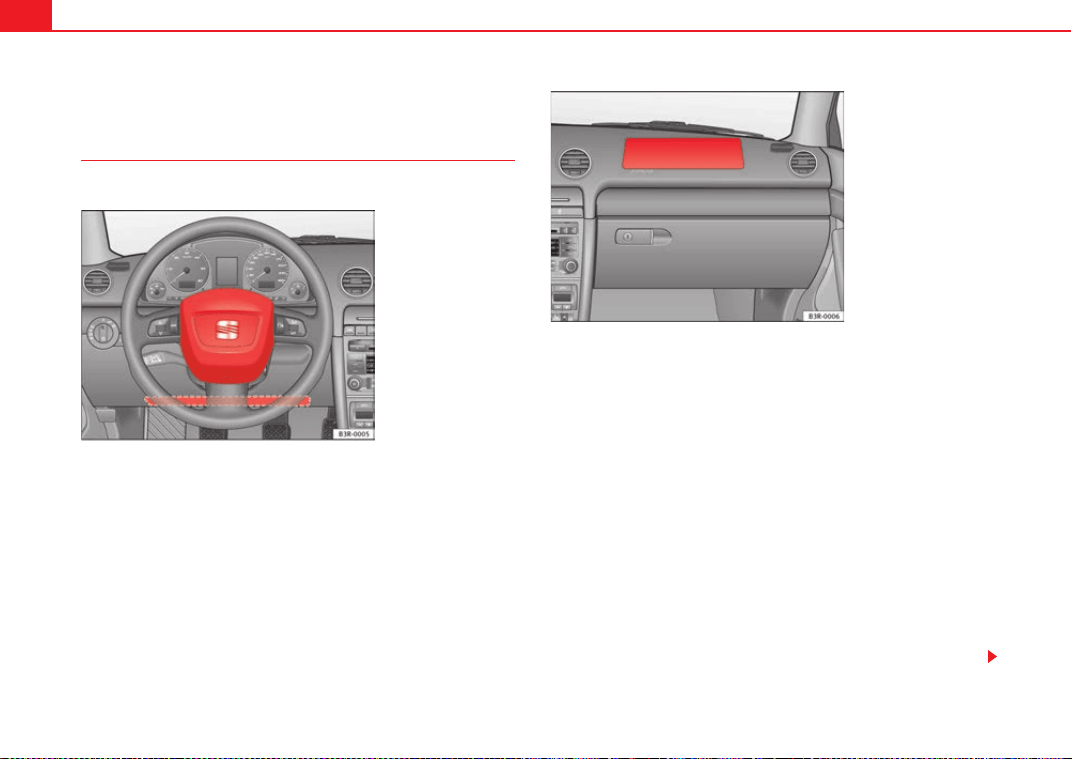
The front airbag for the driver is located in the steering wheel ⇒ fig. 17 and
the airbag for the front passenger is located in the dash panel ⇒ fig. 18.
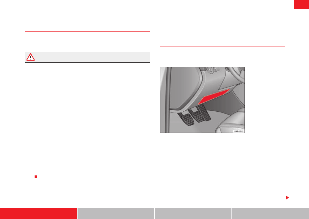
Airbags are identified by the word “AIRBAG”. On the driver side, the knee
airbag* is found in the footwell lining, under the instrument panel.
In conjunction with the seat belts, the front airbag system gives the front
occupants additional protection for the head and chest in the event of a
severe frontal collision ⇒ page 35, “Safety notes on the front airbag system”.
In addition to their normal function of restraining the occupants, the seat
belts also hold the driver and front passenger in a position where the airbags
can provide maximum protection in a frontal collision.
The airbag system is not a substitute for seat belts, but it is an integral part
of the vehicle's overall passive safety system. Please bear in mind that the
airbag system can only work effectively when the occupants are wearing their
seat belts correctly and have adjusted the head restraints properly. Therefore,
it is most important to wear the seat belts at all times, not only because this
is required by law in most countries, but also for your safety ⇒ page 18,
“Brief introduction”.
Fig. 17 Driver airbag in
the steering wheel and
knee airbag in the dash
panel
Fig. 18 Front passenger
airbag located in dash
panel
ExeoST_EN.book Seite 32 Freitag, 3. September 2010 11:41 11
Airbag system 33
Safety First Operating Instructions Practical Tips Technical Specifications
The main parts of the front airbag system are:
• an electronic control and monitoring system (control unit)
• the two front airbags (airbag with gas generator) for the driver and front
passenger,
• a knee airbag* for the driver,
• a warning lamp T on the instrument panel ⇒ page 29
The airbag system operation is monitored electronically. The airbag warning
lamp will light up for a few seconds every time the ignition is switched on
(self-diagnosis).
There is a fault in the system if the warning lamp
T:
• does not light up when the ignition is switched on ⇒ page 29
• turns off and then lights up again after the ignition is switched on,
• lights up or flashes while the vehicle is moving.
The front airbag system will not be triggered if:
• the ignition is switched off
• there is a minor frontal collision,
• there is a side collision,
• there is a rear-end collision
• the vehicle turns over
WARNING
• The seat belts and airbags can only provide maximum protection if the
occupants are seated correctly ⇒ page 10, “Proper sitting position for
occupants”.
• If a fault has occurred in the airbag system, have the system checked
immediately by a qualified workshop. Otherwise, during a frontal collision
the system may fail to trigger, or not trigger correctly.
Operation of front airbags
Inflated airbags reduce the risk of head or chest injury.
The airbag system is designed so that the airbags for the driver and front
passenger are triggered in a severe frontal collision.
In certain types of accident the front, curtain and side airbags may be trig-
gered together.
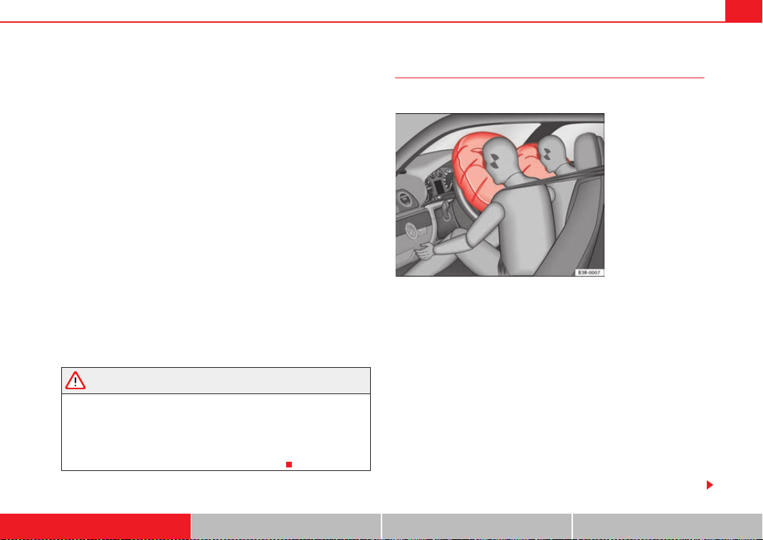
When the system is triggered, the airbags fill with a propellant gas and
deploy in front of the driver and front passenger ⇒ fig. 19. The fully deployed
airbags cushion the forward movement of the front occupants and help to
reduce the risk of injury to the head and the upper part of the body.
The special design of the airbag allows the controlled escape of the propel-
lant gas when an occupant puts pressure on the bag. Thus, the head and
chest are surrounded and protected by the airbag. After the collision, the
airbag deflates sufficiently to allow visibility.
The airbags deploy extremely rapidly, within thousandths of a second, to
provide additional protection in the event of an accident. A fine dust may
Fig. 19 Inflated front
airbags
ExeoST_EN.book Seite 33 Freitag, 3. September 2010 11:41 11
Airbag system34
develop when the airbag deploys. This is normal and it is not an indication of
fire in the vehicle.
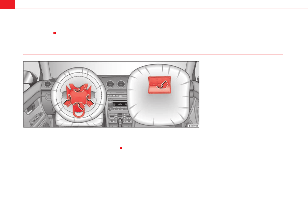
Airbag covers when the frontal airbags are triggered
The airbag covers fold out of the steering wheel or dash panel when the driver
and front passenger airbags are triggered ⇒ fig. 20. The airbag covers
remain connected to the steering wheel or the dash panel.
Fig. 20 Airbag covers reacting when the front airbags
are triggered
ExeoST_EN.book Seite 34 Freitag, 3. September 2010 11:41 11
Airbag system 35
Safety First Operating Instructions Practical Tips Technical Specifications
Safety notes on the front airbag system
If you use airbags correctly, they can considerably reduce the
risk of injury in many kinds of accident.
WARNING
• It is important for the driver and front passenger to keep a distance of
at least 25 cm from the steering wheel or dash panel. If the minimum
distance is not observed then the airbags do not correctly protect the
vehicle occupants; risk of fatal injuries! In addition, the front seats and
head restraints must always be positioned correctly for the height of the
occupant.
• If you are not wearing a seat belt, if you lean forward or to the side while
travelling or assume an incorrect sitting position, there is a substantially
increased risk of injury. This increased risk of injury will be further
increased if you are struck by an inflating airbag.
• Never let a child travel on the front seat without an appropriate restraint
system. If the airbag is triggered in an accident, children can sustain
serious or fatal injuries from the airbag as it inflates ⇒ page 46, “Child
safety”.
• The deployment space between the front passengers and the airbags
must not in any case be occupied by other passenger, pets and objects.
• The airbags provide protection for just one accident; replace them once
they have deployed.
• It is also important not to attach any objects such as cup holders or
telephone mountings to the surfaces covering the airbag units.
• Do not attempt to modify components of the airbag system in any
way.
Knee airbag*
Description of the knee airbag
The airbag system provides additional protection to front seat
passengers if they are properly secured.
The knee airbag for the driver is located in the dash panel underneath the
steering wheel.⇒ fig. 21.
The knee airbag offers additional protection to the driver's knees and upper
and lower thigh areas as a supplement to the seat belts.
If the front airbags deploy, the knee airbag also deploys in severe frontal
collisions.⇒ page 33
Besides their normal safety function, seat belts help keep the driver in posi-
tion in case of a frontal collision so that the airbags can provide protection.
The airbag system is not a substitute for seat belts. It is, on the other hand,
part of the overall occupant safety system of your vehicle. Always remember
Fig. 21 Driver knee
airbag
ExeoST_EN.book Seite 35 Freitag, 3. September 2010 11:41 11
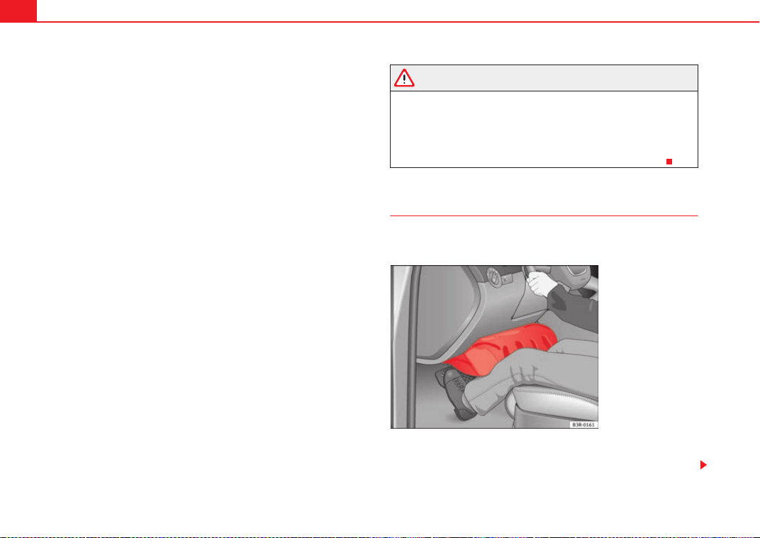
Airbag system36
that the airbag system can only help to protect you if you are wearing your
seat belt and wearing it properly.
Remember too that airbags will deploy only once and only in certain kinds of
accidents - your seat belts are always there to offer protection in those acci-
dents in which airbags are not supposed to deploy or when they have already
deployed, for example when your vehicle strikes or is struck by another after
the first collision.
This is just one of the reasons why an airbag is not a substitute for the seat
belt. The airbag system works most effectively when used with the seat belts.
Therefore, always wear your seat belts correctly.
It is important to remember that while the airbag system is designed to
reduce the possibility of serious injuries, other injuries, for example,
swelling, bruising, and minor abrasions can also be associated with airbags.
The knee airbag system basically consists of:
• The electronic control module
• One inflatable airbag (airbag and gas generator) for the driver
• An airbag indicator light on the instrument panel
The knee airbag system will not be triggered:
• if the ignition is switched off
• in frontal collisions when the deceleration measured by the control unit is
too low
• in side collisions
• in rear-end collisions
• in rollovers
• in the event of a system malfunction (hazard warning lights/turn signals
illuminated).⇒ page 65
WARNING
• Seat belts and the airbag system can only provide protection when
occupants are in the proper seating position.
• If the airbag indicator light comes on when the vehicle is being used,
have the system inspected immediately by your Authorised Service Centre.
The airbag may not work properly when the vehicle acceleration in a side
collision is high enough to deploy the airbag. See also ⇒ page 65.
How knee airbags work
The risk of injury to the leg area is reduced by fully deployed
knee airbags.
The knee airbag system has been designed so that the airbag for the driver is
deployed in certain but not all frontal collisions.
Fig. 22 Inflated airbags
protect in a frontal colli-
sion.
ExeoST_EN.book Seite 36 Freitag, 3. September 2010 11:41 11
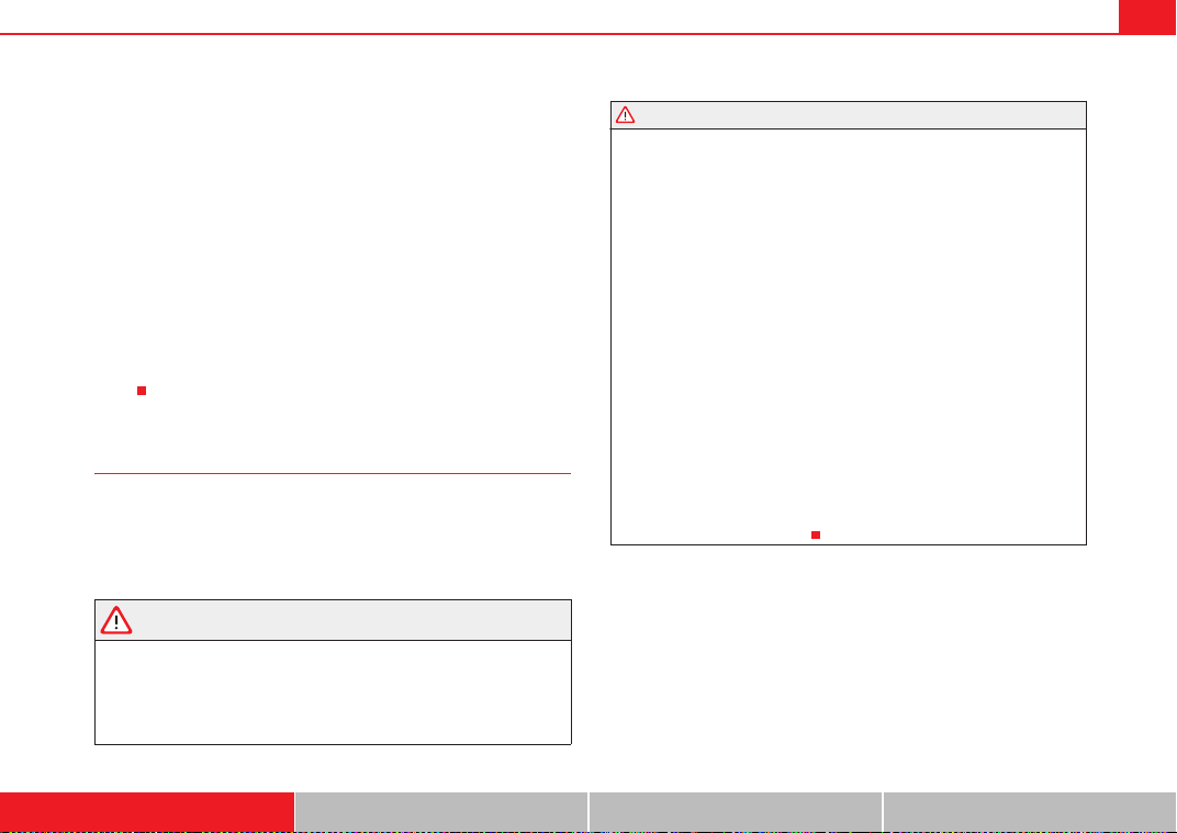
Airbag system 37
Safety First Operating Instructions Practical Tips Technical Specifications
If the front airbag deploys, the knee airbag also deploys in severe frontal colli-
sions.
When the system is deployed, the airbag starts to fill with a propellant gas,
and inflates between the lower part of the dash panel and the
driver.⇒ page 36, fig. 22
Although they are not a soft pillow, they can cushion the impact and in this
way they can help to reduce the risk of injury to the lower extremities.
All this takes place instantaneously, so fast that many people do not even
realise that the airbags have deployed. The airbags also inflate with a great
deal of force and it is important for occupant safety that nothing should be in
their way when they deploy.
Fully inflated airbags in combination with properly worn seat belts slow down
and limit the occupant's forward movement and help to reduce the risk of
injury.
Important safety notes on the knee airbag system
Airbags are only additional safety
Always wear seat belts correctly and drive in a proper seated position. There
is a lot of information that you and your passengers should know and do so
that the seat belts and airbags can provide additional protection.
WARNING
An inflating knee airbag can cause serious injuries. Wearing seat belts
incorrectly and improper seating positions increase the risk of serious
personal injury and death whenever a vehicle is being used.
• The airbag system cannot protect you properly if you are seated too
close to any of the airbag locations. When adjusting the seat positions, it
is important for the driver to keep the upper body and knees at the
following minimum safety distances:
− 25 cm between the chest and the steering wheel/dash panel.
− 10 cm between the knees and the lower part of the dash panel.
• The risk of personal injury increases if you lean forward or to the side,
or if the seat is improperly positioned and you are not wearing your seat
belt. The risk increases even more should the airbag deploy.
• Always make sure that the knee airbag can inflate without interference.
Objects between yourself and the airbag can increase the risk of injury in
an accident by interfering with the way the airbag deploys or by being
thrust into you as the airbag deploys.
− No objects of any kind should be carried in the footwell area in front
of the driver's seat. Bulky objects (shopping bags, for example) can
hinder or prevent proper deployment of the airbag. Small objects can
be thrown through the vehicle if the airbag deploys and injure you or
your passengers.
• Make sure there are no cracks, deep scratches or other damage in the
area of the dash panel where the knee airbag is located.
• If children are incorrectly seated, their risk of injury increases in the
case of an accident.⇒ page 46
WARNING (continued)
ExeoST_EN.book Seite 37 Freitag, 3. September 2010 11:41 11
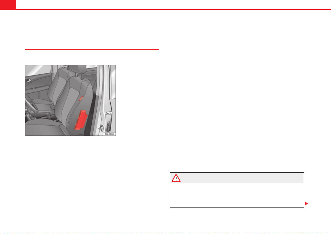
Airbag system38
Side airbags*
Description of side airbags
The airbag system is not a substitute for the seat belts.
The front side airbags are located in the driver seat and front passenger seat
backrests ⇒ fig. 23. The rear side airbags* are located in the rear wheel
housing lining. The locations are identified by the text “AIRBAG” in the upper
region of the backrests and in the rear wheel housing lining.
Together with the seat belts, the side airbag system gives the front seat occu-
pants additional protection for the upper body in the event of a severe side
collision ⇒ page 40, “Safety notes on the operation of the side airbag
system”.
In a side collision, the side airbags reduce the risk of injury to passengers on
the front seats to the areas of the body facing the impact. In addition to their
normal function of protecting the occupants in a collision, the seat belts also
hold the passengers in the front seats and the outer rear seats in a position
where the side airbags can provide maximum protection.
The airbag system is not a substitute for seat belts, but it is an integral part
of the vehicle's overall passive safety system. Please bear in mind that the
airbag system can only work effectively when the occupants are wearing their
seat belts. Therefore, it is most important to wear the seat belts at all times,
not only because this is required by law in most countries, but also for your
safety ⇒ page 18, “Brief introduction”.
The side airbag system will not be triggered if:
• the ignition is switched off
• there is a minor side collision
• there is a frontal collision
• there is a rear-end collision
• the vehicle turns over
The main parts of the airbag system are:
• an electronic control and monitoring system (control unit)
• The front side airbags in the backrests of the front seats and the rear side
airbags in the lining of the rear wheel housing
• a warning lamp T on the instrument panel ⇒ page 29
The airbag system operation is monitored electronically. The airbag warning
lamp will light up for approx. 4 seconds every time the ignition is switched on
(self-diagnosis).
WARNING
• In a side collision, the side airbags will not work, if the sensors do not
correctly measure the pressure increase on the interior of the doors, due to
air escaping through the areas with holes or openings in the door panel.
• Never drive the vehicle if the interior panels have been removed.
Fig. 23 Side airbag in
driver seat
ExeoST_EN.book Seite 38 Freitag, 3. September 2010 11:41 11
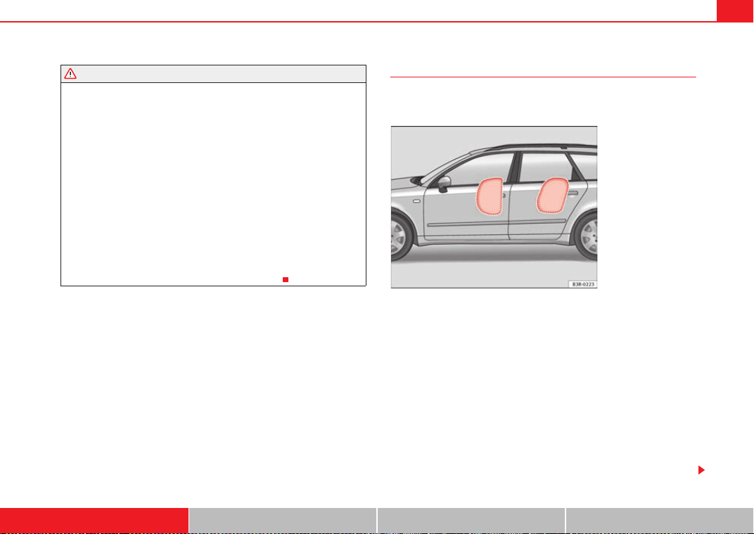
Airbag system 39
Safety First Operating Instructions Practical Tips Technical Specifications
• Never drive if the interior door panels have been removed or if the
panels have not been correctly fitted.
• Never drive the vehicle if the loudspeakers in the door panels have
been removed, unless the holes left by the loudspeakers have been
correctly closed.
• Always check that the openings are closed or covered if loudspeakers
or other equipment are fitted in the interior door panels.
• Any work carried out to the doors should be made in a specialised work-
shop.
• The seat belts and airbags can only provide maximum protection if the
occupants are seated correctly ⇒ page 10, “Proper sitting position for
occupants”.
• If a fault has occurred in the airbag system, have the system checked
immediately by a qualified workshop. Otherwise, during a side collision,
the system may fail to trigger, or not trigger correctly.
Operation of side airbags
Inflated airbags can reduce the risk of head or chest injury in
many side impact collisions.
In some side collisions, the side airbag is triggered on the impact side of the
vehicle ⇒ fig. 24.
In certain types of accident the front, curtain and side airbags may be trig-
gered together.
When the system is triggered, the airbag is filled with propellant gas.
The airbags deploy extremely rapidly, within thousandths of a second, to
provide additional protection in the event of an accident. A fine dust may
develop when the airbag deploys. This is normal and it is not an indication of
fire in the vehicle.
The fully deployed airbags cushion the movement of the occupants of the
front seats and the outer rear seats and help to reduce the risk of injury to the
upper body.
WARNING (continued)
Fig. 24 Inflated side
airbag on left side of
vehicle
ExeoST_EN.book Seite 39 Freitag, 3. September 2010 11:41 11
Airbag system40
The special design of the airbag allows the controlled escape of the propel-
lant gas when an occupant puts pressure on the bag. Thus, the head and
chest are surrounded and protected by the airbag.
Safety notes on the operation of the side airbag system
If airbags are used correctly, they can considerably reduce the
risk of injury in side impact collisions.
WARNING
• If you do not wear a seat belt, if you lean forward, or are not seated
correctly while the vehicle is in motion, you are at a greater risk of injury if
the side airbag system is triggered in an accident.
• In order for the side airbags to provide their maximum protection, the
prescribed sitting position must always be maintained with seat belts
fastened while travelling.
• Occupants of the outer seats must never carry any objects or pets in the
deployment space between them and the airbags, or allow children or
other passengers to travel in this position. It is also important not to attach
any accessories (such as cup holders) to the doors. This would impair the
protection offered by the side airbags.
• The built-in coat hooks should be used only for lightweight clothing. Do
not leave any heavy or sharp-edged objects in the pockets.
• Great forces, such as hard blows or kicks, must not be exerted upon the
backrest bolster because the system may be damaged. In this case, the
side airbags would not be triggered.
• Under no circumstances should protective covers be fitted over seats
with side airbags unless the covers have been approved for use in your
vehicle. Because the airbag is triggered from the side of the backrest, the
use of non-approved seat covers would obstruct the side airbag, seriously
reducing the airbag's effectiveness ⇒ page 223, “Accessories, parts
replacement and modifications”.
• Any damage to the original seat upholstery or around the seams of the
side airbag units must be repaired immediately by a specialised workshop.
• The airbags provide protection for just one accident; replace them once
they have deployed.
• When children assume an incorrect sitting position, they expose them-
selves to an increased risk of injury in the event of an accident. This is
particularly the case if the child is travelling on the front passenger seat
and the airbag system is triggered in an accident; this could have critical
consequences including serious injury or death ⇒ page 46, “Child safety”.
• Any work on the side airbag system or removal and installation of the
airbag components for other repairs (such as removal of the front seat)
should only be performed by a qualified workshop. Otherwise, faults may
occur during the airbag system operation.
• Do not attempt to modify components of the airbag system in any way.
• The side and head airbags are managed through sensors located in the
interior of the front doors. To ensure the correct functioning of the side and
head airbags neither the doors nor the door panels should be modified in
any way (e.g. fitting loudspeakers). If the front door is damaged, the airbag
system may not work correctly. All work carried out on the front door must
be made in a qualified workshop.
WARNING (continued)
ExeoST_EN.book Seite 40 Freitag, 3. September 2010 11:41 11
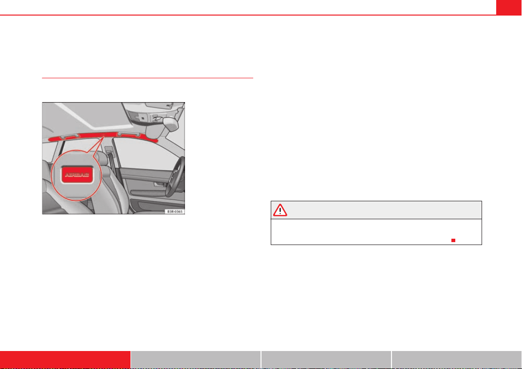
Airbag system 41
Safety First Operating Instructions Practical Tips Technical Specifications
Curtain airbags
Description of curtain airbags
The airbag system is not a substitute for the seat belts.
The curtain airbags are located on both sides in the interior above the doors
⇒ fig. 25 and are identified with the text “AIRBAG”.
In conjunction with the seat belts, the curtain airbag system gives the occu-
pants additional protection for the head and upper body in the event of a
severe side collision ⇒ page 42, “Safety notes on the operation of the
curtain airbag system”.
The airbag system is not a substitute for seat belts, but it is an integral part
of the vehicle's overall passive safety system. Please bear in mind that the
airbag system can only work effectively when the occupants are wearing their
seat belts correctly and have adjusted the head restraints properly. Therefore,
it is most important to wear the seat belts at all times, not only because this
is required by law in most countries, but also for your safety ⇒ page 18,
“Brief introduction”.
The main parts of the curtain airbag system are:
• an electronic control and monitoring system (control unit)
• the curtain airbags (airbags with gas generator) for the driver, front
passenger and passengers on the rear seats,
• a warning lamp T on the instrument panel ⇒ page 29
The airbag system operation is monitored electronically.
The curtain airbag system will not be triggered if:
• the ignition is switched off
• there is a frontal collision
• there is a rear-end collision
• the vehicle turns over
• there is a minor side collision
WARNING
If a fault has occurred in the airbag system, have the system checked imme-
diately by a qualified workshop. Otherwise there is a danger that during a
collision, the system may fail to trigger, or not trigger correctly.
Fig. 25 Location of head
airbags on the left side of
the vehicle
ExeoST_EN.book Seite 41 Freitag, 3. September 2010 11:41 11
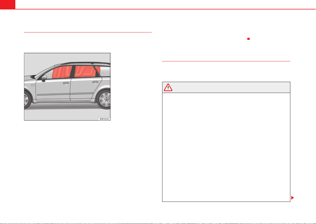
Airbag system42
Operation of curtain airbags
Fully inflated airbags reduce the risk of head or chest injury in
a side collision.
During some side collisions the curtain airbag is triggered on the impact side
of the vehicle ⇒ fig. 26.
In certain types of accident the front, side and curtain airbags may be trig-
gered together.
When the system is triggered, the airbag is filled with propellant gas. In the
process, the curtain airbag covers the side windows and door pillars.
The airbags deploy extremely rapidly, within thousandths of a second, to
provide additional protection in the event of an accident. A fine dust may
develop when the airbag deploys. This is normal and it is not an indication of
fire in the vehicle.
The fully deployed airbags cushion the movement of the front occupants and
help to reduce the risk of injury to the upper body.
The special design of the airbag allows the controlled escape of the propel-
lant gas when an occupant puts pressure on the bag. Thus, the head and
chest are surrounded and protected by the airbag.
Safety notes on the operation of the curtain airbag system
If you use airbags correctly, they can considerably reduce the
risk of injury in many kinds of accident.
WARNING
• In order for the side airbags to provide their maximum protection, the
prescribed sitting position must always be maintained with seat belts
fastened while travelling.
• For safety reasons, the curtain airbag must be disconnected in those
vehicles fitted with a passenger compartment separation screen. See an
Authorised Service Centre to make this adjustment.
• There must be no other persons, animals or objects between the occu-
pants of the outer seats and the deployment space of the curtain airbags
so that the curtain airbag can deploy without restriction and provide the
greatest possible protection. Therefore, sun blinds which have not been
expressly approved for use in your vehicle may not be attached to the side
windows ⇒ page 223, “Accessories, parts replacement and modifica-
tions”.
• The built-in coat hooks should be used only for lightweight clothing. Do
not leave any heavy or sharp-edged objects in the pockets. Please, do not
hang the clothes on coat hangers.
• The airbags provide protection for just one accident; replace them once
they have deployed.
• Any work on the curtain airbag system or removal and installation of
the airbag components for other repairs (such as removal of the roof lining)
Fig. 26 Deployed curtain
airbags
ExeoST_EN.book Seite 42 Freitag, 3. September 2010 11:41 11
Airbag system 43
Safety First Operating Instructions Practical Tips Technical Specifications
should only be performed by a qualified workshop. Otherwise, faults may
occur during the airbag system operation.
• Do not attempt to modify components of the airbag system in any way.
• The side and head airbags are managed through sensors located in the
interior of the front doors. To ensure the correct functioning of the side and
head airbags neither the doors nor the door panels should be modified in
any way (e.g. fitting loudspeakers). If the front door is damaged, the airbag
system may not work correctly. All work carried out on the front door must
be made in a qualified workshop.
WARNING (continued)
ExeoST_EN.book Seite 43 Freitag, 3. September 2010 11:41 11
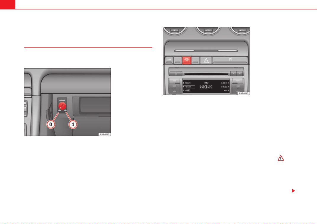
Airbag system44
Deactivating airbags
Front passenger airbag deactivation
If you fit a rear-facing child seat to the front passenger seat,
the front passenger airbag must be de-activated.
When the passenger airbag is deactivated, only the front airbag is
deactivated. All the other airbags in the vehicle remain activated.
Deactivating the front passenger airbag
– Switch the ignition off.
– Turn the ignition key in the key-operated switch in the glove
compartment to position OFF ⇒ fig. 27.
– Check that the warning lamp “OFF” on the instrument panel
⇒ fig. 28 remains lit when the ignition is switched on ⇒ .
Activating the front passenger airbag
– Switch the ignition off.
– Turn the ignition key in the key-operated switch in the glove
compartment to position ON ⇒ fig. 27.
Fig. 27 In the glove
compartment: switch for
activating and deacti-
vating the front passenger
airbag
Fig. 28 Warning lamp for
deactivated passenger
airbag in centre console
A
0
A
1
ExeoST_EN.book Seite 44 Freitag, 3. September 2010 11:41 11
Airbag system 45
Safety First Operating Instructions Practical Tips Technical Specifications
– Check that the warning lamp on the instrument panel
⇒ page 44, fig. 28 does not light up when the ignition is
switched on ⇒ .
WARNING
• The driver is responsible for the proper position of the key-operated
switch.
• You should only deactivate the front passenger airbag when, in excep-
tional cases, you have to use a rear-facing child seat on the front passenger
seat ⇒ page 46, “Child safety”.
• Never install a child seat facing backwards on the front passenger seat
unless the front passenger airbag has been disabled. Otherwise, there is a
risk of death. If under exceptional circumstances it is necessary to trans-
port a child in a rear-facing child seat on the front passenger seat, you must
always disable the front passenger airbag.
• As soon as the child seat is no longer needed on the front passenger
seat, enable the front passenger airbag again.
• Only deactivate the passenger airbag when the ignition is off, other-
wise a fault may occur in the airbag system, which could cause the airbag
to not deploy properly or not deploy at all.
• When the passenger airbag is deactivated, if the warning lamp AIRBAG
OFF is not continuously lit up, there may be a fault in the airbag system:
− Have the airbag system inspected immediately by a qualified work-
shop.
− Do not use a child seat on the front passenger seat! The front
passenger airbag could be triggered despite the fact that there is a fault
in the system and, as a result, a child could sustain serious or fatal inju-
ries.
− It is unpredictable whether the front passenger airbag will deploy in
the event of an accident. Warn all your passengers of this.
• When using the ignition key to activate/deactivate the front passenger
airbag, only the front passenger airbag will be activated/deactivated. The
side airbag and head airbag on the passenger side will remain active.
WARNING (continued)
ExeoST_EN.book Seite 45 Freitag, 3. September 2010 11:41 11
Child safety46
Child safety
Brief introduction
Introduction
Statistics show that children are generally safer on the rear
seat than on the front passenger seat.
For safety reasons we recommend that children under 12 years of age travel
on the rear seats. Depending on their age, height and weight, children trav-
elling on the rear seat must use a child seat or a seat belt. It is advisable that
children always travel in the rear seats, the rear central position being the
safest seat, since the risk of injuries in a side collision is diminished.
The physical laws involved and the forces acting in a collision apply also to
children. ⇒ page 19, “Why wear seat belts?”. But unlike adults, children do
not have muscle and bone structures fully developed. This means that chil-
dren are subject to a greater risk of injury.
To reduce this risk, children must always use special child restraint systems
when travelling in the vehicle.
We recommend the use of child safety products from the SEAT Genuine Acces-
sories Programme, which includes systems for all ages made by “Peke”
1)
.
These systems have been especially designed and approved, complying with
the ECE-R44. regulation.
Follow the manufacturer's instructions and observe any statutory require-
ments when installing and using child seats. Always read and note
⇒ page 46, “Safety notes on using child seats”.
We recommend you to include the manufacturer's Child Seat instruction
manual together with the on-board documentation.
Safety notes on using child seats
Proper use of child seats substantially reduces the risk of
injury in an accident!
As the driver, you are responsible for any children you transport in
your vehicle.
– Protect your children by properly using the appropriate child
seats ⇒ page 48.
– Always ensure that the seat belt is properly positioned according
to the instructions provided by the manufacturer of the child
seat.
– When travelling, do not allow children to distract you from traffic.
– Take breaks regularly during long trips. Take a break at least
every two hours.
WARNING
• Never install a child seat facing backwards on the front passenger seat
unless the front passenger airbag has been disabled. This could lead to a
risk of potentially fatal injuries to the child! However, if it is necessary, in
exceptional cases, to transport a child in the front passenger seat, the front
passenger airbag must always be disabled ⇒ page 44, “Deactivating
1)
Not for all countries
ExeoST_EN.book Seite 46 Freitag, 3. September 2010 11:41 11
Child safety 47
Safety First Operating Instructions Practical Tips Technical Specifications
airbags”. If the passenger seat has a height adjustment option, move it to
the highest position.
• For those vehicles that do not include a key lock switch to disconnect
the airbag, the vehicle must be taken to a Technical Service.
• All passengers, especially children, must assume the proper sitting
position and be properly belted in while travelling.
• Never hold children or babies on your lap, this can result in potentially
fatal injuries to the child!
• Never allow a child to be transported in a vehicle without being properly
secured, or to stand up or kneel on a seat while travelling. In an accident,
the child could be flung through the vehicle, causing possibly fatal injuries
to themselves and to the other passengers.
• If children assume an improper sitting position when the vehicle is
moving, they expose themselves to greater risk of injury in the event of a
sudden braking manoeuvre or in an accident. This is particularly important
if the child is travelling on the front passenger seat and the airbag system
is triggered in an accident; as this could cause serious injury or even death.
• A suitable child seat can protect your child!
• Never leave an unsupervised child alone on a child seat or in the
vehicle.
• Depending on weather conditions, it may become extremely hot or cold
inside the vehicle. This can be fatal.
• Children who are less than 1.5 metres tall must not wear a normal seat
belt without a child seat, as this could cause injuries to the abdominal and
neck areas during a sudden braking manoeuvre or in an accident.
• Do not allow the seat belt to become twisted or jammed, or to rub on
any sharp edges.
• Incorrectly worn seat belts can cause injuries even in a minor collision
or in sudden braking manoeuvres.
• The seat belt provides maximum protection only when the seat belt is
properly positioned ⇒ page 22, “Seat belts”.
• Only one child may occupy a child seat ⇒ page 48, “Child seats”.
WARNING (continued) WARNING (continued)
ExeoST_EN.book Seite 47 Freitag, 3. September 2010 11:41 11
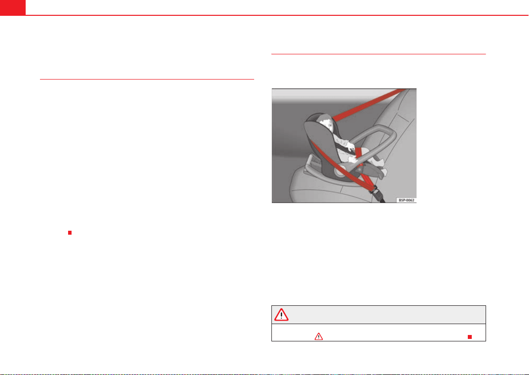
Child safety48
Child seats
Categorisation of child seats into groups
Use only child seats that are officially approved and suitable
for the child.
Child seats are subject to the regulation ECE-R 44. ECE-R stands for: Economic
Commission for Europe Regulation
The child seats are grouped into 5 categories:
Group 0: children up to 10 kg
Group 0+: children up to 13 kg
Group 1: from 9 to 18 kg
Group 2: from 15 to 25 kg
Group 3: from 22 to 36 kg
Child seats that have been tested and approved under the ECE R 44 standard
bear the test mark on the seat (the letter E in a circle with the test number
below it).
Group 0 and 0+ child seats
A suitable child seat and a correctly adjusted seat belt can
help you to protect your child.
Group 0: For babies from about 9 months old and 10 kg in weight the most
suitable seats are those appearing in the illustration ⇒ fig. 29.
Group 0+: For babies from about 18 months old and 13 kg in weight the most
suitable seats are those appearing in the illustration.
Follow the manufacturer's instructions and observe any statutory require-
ments when installing and using child seats.
We recommend you to include the manufacturer's Child Seat instruction
manual together with the on-board documentation.
WARNING
Read and always observe information and warnings concerning the use of
child seats ⇒ in “Safety notes on using child seats” on page 46.
Fig. 29 A group 0 rear-
facing child seat fitted on
the rear seat.
ExeoST_EN.book Seite 48 Freitag, 3. September 2010 11:41 11
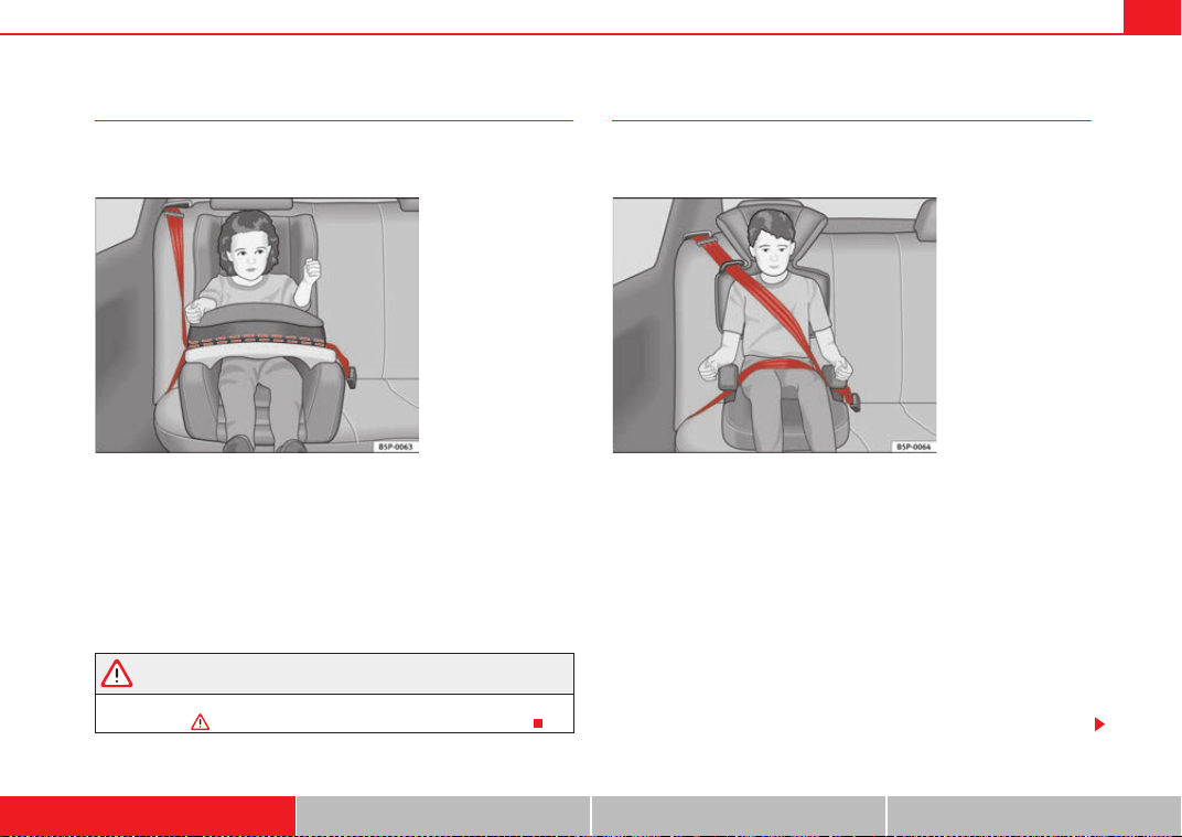
Child safety 49
Safety First Operating Instructions Practical Tips Technical Specifications
Group 1 child seats
A suitable child seat and a correctly adjusted seat belt can
help you to protect your child.
Child seats using the ISOFIX system or seats in which the child faces the rear
of the vehicle are most appropriate for babies and small children weighing
between 9 and 18 kg.
Follow the manufacturer's instructions and observe any statutory require-
ments when installing and using child seats.
We recommend you to include the manufacturer's Child Seat instruction
manual together with the on-board documentation.
WARNING
Read and always observe information and warnings concerning the use of
child seats ⇒ in “Safety notes on using child seats” on page 46.
Group 2 and 3 child seats
A suitable child seat and a correctly adjusted seat belt can
help you to protect your child.
Follow the manufacturer's instructions and observe any statutory require-
ments when installing and using child seats.
We recommend you to include the manufacturer's Child Seat instruction
manual together with the on-board documentation.
Group 2 child seats
Children under 7 years of age weighing between 15 and 25 kg are best
protected by group 2 child seats together with properly adjusted seat belts.
Group 3 child seats
Children over 7 years of age weighing between 22 and 36 kg but less than 1.5
metres tall are best protected by seat cushions with head restraints together
with properly worn seat belts ⇒ fig. 31.
Fig. 30 A category 1
forward-facing child seat
fitted on the rear seat.
Fig. 31 Forward-facing
child seat installed on rear
seat.
ExeoST_EN.book Seite 49 Freitag, 3. September 2010 11:41 11
Child safety50
WARNING
• The shoulder part of the seat belt must lie approximately on the centre
of the shoulder, never across the neck or the arm. The seat belt must lie
close to the upper part of the body. The lap belt part must lie across the
pelvis, not across the stomach, and always fit closely. Pull the belt tight if
necessary to take up any slack ⇒ page 22, “Seat belts”.
• Read and always observe information and warnings concerning the use
of child seats ⇒ in “Safety notes on using child seats” on page 46.
ExeoST_EN.book Seite 50 Freitag, 3. September 2010 11:41 11
Child safety 51
Safety First Operating Instructions Practical Tips Technical Specifications
Securing child seats
Ways to secure a child seat
A child seat can be secured differently on the rear seat and on
the front passenger seat.
You can secure a child seat to the rear seat or front passenger seat in the
following ways:
• Child seats in groups 0 to 3can be secured with a seat belt.
• Seats for children aged 0, 0+ and 1 with the “ISOFIX” system can be
secured without fastening seat belts, using the “ISOFIX”and/or Top Tether
securing rings ⇒ page 52.
U: Suitable for universal approved restraining systems for use in this age
category (universal retention systems are those fitted using the adult
seat belt).
*: Move the front passenger seat as far back as possible, as high as
possible and always deactivate the airbag.
L: Suitable for retention systems using the “ISOFIX” anchors.
WARNING
• When travelling, children must be secured in the vehicle with a
restraint system suitable for age, weight and size.
• Never install a child seat facing backwards on the front passenger seat
unless the front passenger airbag has been disabled. This could cause fatal
injuries to the child! However, if, in exceptional cases, it is necessary to
transport a child in the front passenger seat, the front passenger airbag
⇒ page 44, “Deactivating airbags” must always be disabled and the seat
adjusted to its highest position, where possible.
• Read and always observe information and warnings concerning the use
of child seats ⇒ in “Safety notes on using child seats” on page 46.
Category Weight
Seat locations
Front
passenger
Rear outer Rear centre
Group 0 <10 kg U* U/L U
Group 0+ <13 kg U* U/L U
Group 1 9-18 kg U* U/L U
Group 2 / 3 15-36 kg U* U U
ExeoST_EN.book Seite 51 Freitag, 3. September 2010 11:41 11
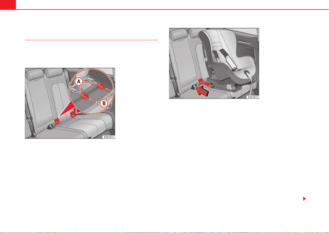
Child safety52
Child seat mounting using the “ISOFIX” and/or Top Tether
system
The Child restraint systems may be fitted to the rear seat
quickly and safely with the “ISOFIX” and/or Top Tether system
(fitted to the rear backrest).
Following the instructions given by the child seat manufacturer
when installing and removing the seat.
– Fit the plastic guides on the vehicle's ISOFIX anchorages
between the backrest and the seat ⇒ fig. 32.
– Slide the child seat anchorages along the plastic guides until
secured in the vehicle's ISOFIX rings (when correctly closed, you
will hear a click and the seat should also have a visual indicator
to confirm it is correctly secured) ⇒ fig. 33.
– Check that the ISOFIX system is correctly secured by pulling on
the child seat.
Detailed fitting instructions are supplied with the child safety seat.
Child seats with “ISOFIX” mountings are available from Dealers and specialist
retailers.
Fig. 32 Position of the
ISOFIX anchors on the
side rear seat
Fig. 33 The ISOFIX child
seat anchors slide along
the fitted plastic guides
until secured in the
vehicle's ISOFIX anchor-
ages
ExeoST_EN.book Seite 52 Freitag, 3. September 2010 11:41 11
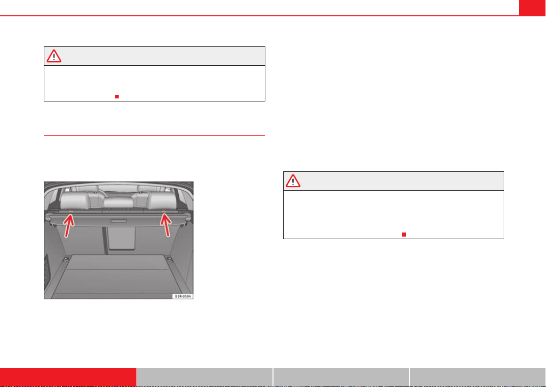
Child safety 53
Safety First Operating Instructions Practical Tips Technical Specifications
WARNING
The retainers employed for this child safety seat are specially designed for
the “ISOFIX” system. Never secure other child seats, seat belts or other
items into the retainers. If you do, you increase the risk of sustaining
severe or fatal injuries.
Top Tether retainer straps
Some child restraint seats have a third Top Tether anchoring
point, apart from both “ISOFIX” anchoring points, which
allow better child retention.
The Top Tether system has an upper strap for attachment to the vehicle's
upper anchoring point, which is found on the rear luggage compartment
cover.
The retainer strap is used to reduce forwards movements of the safety seat in
a crash, helping reduce the risk of injuries to the head from hitting the inside
of the vehicle.
It is foreseen that an EU Directive will introduce requirements related to the
retention of child restraint systems by means of ISOFIX and Top Tether anchor-
ages (probably compulsory for new types from 2010), which will entail
improved retention of the child restraint seat and less head movement in
case of frontal collisions.
Use of retainer straps on rear-facing seats
At present there are very few rear-facing child safety seats fitted with a
retainer strap. Please carefully read and follow the safety seat manufacturer's
instructions for information on how to install the retainer strap properly.
WARNING
An undue installation of the safety seat will increase the risk of injury in the
event of a crash.
• Never tie the retainer strap to a hook in the luggage compartment.
• Never secure or tie luggage or other items to the lower anchorages
(ISOFIX) or the upper ones (Top Tether).
Fig. 34 Position of the
Top Tether rings on the
rear tray
ExeoST_EN.book Seite 53 Freitag, 3. September 2010 11:41 11
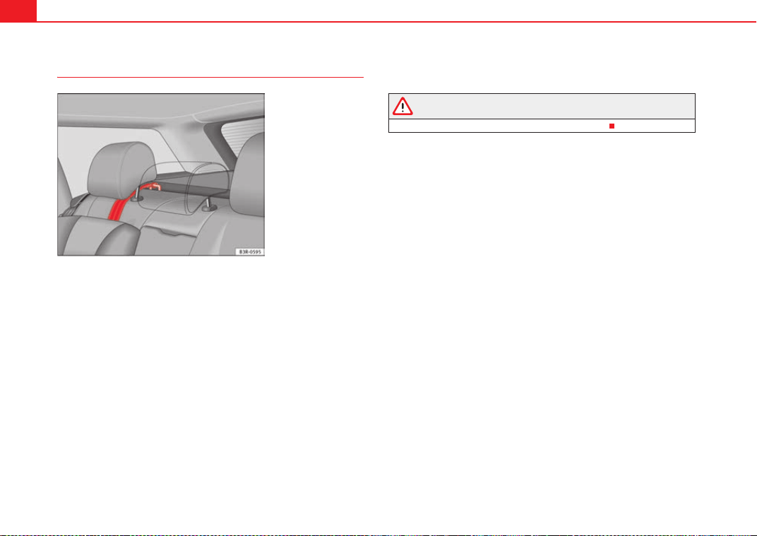
Child safety54
Fitting the Top Tether child restraint to the anchoring point
Securing the Top Tether child restraint to the anchoring point
situated on the rear shelf
– Pull out the fastening belt of the child restraint seat according to
the manufacturer's instructions.
– Lead the Top Tether fastening belt under the rear seat head
restraint ⇒ fig. 35 (lift the head restraint where necessary).
– Slide the belt so that the Top Tether belt of the child restraint seat
is correctly secured to the rear shelf anchorage.
– Firmly tighten the Top Tether belt following the child restraint
seat manufacturer's instructions.
Releasing the retaining strap
– Release the retainer strap in line with the instructions given by
the child safety seat manufacturer.
– Push the lock and release it from the anchoring support.
WARNING
Read and bear in mind all the WARNINGS ⇒ page 53.
Fig. 35 Retainer strap:
correct adjustment and
fitting
ExeoST_EN.book Seite 54 Freitag, 3. September 2010 11:41 11

55
Safety First Operating Instructions Practical Tips Technical Specifications
ExeoST_EN.book Seite 55 Freitag, 3. September 2010 11:41 11
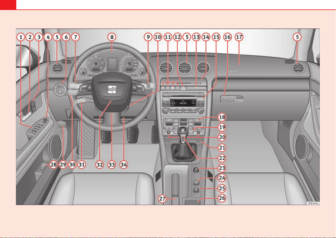
56
Fig. 36 Some of the equipment listed in this section is only fitted on certain models or are optional extras.
ExeoST_EN.book Seite 56 Freitag, 3. September 2010 11:41 11

Cockpit 57
Safety First Operating Instructions Practical Tips Technical Specifications
Operating Instructions
Cockpit
Overview
Dash panel overview
Electric windows . . . . . . . . . . . . . . . . . . . . . . . . . . . . . . . . . . . .
Door handle
Central locking switch . . . . . . . . . . . . . . . . . . . . . . . . . . . . . . . .
Electric control for exterior mirrors . . . . . . . . . . . . . . . . . . . . . .
Air outlets with thumbwheel . . . . . . . . . . . . . . . . . . . . . . . . . .
Light switch . . . . . . . . . . . . . . . . . . . . . . . . . . . . . . . . . . . . . . . .
Lever for turn signals and main beam headlights . . . . . . . . . .
Instrument panel . . . . . . . . . . . . . . . . . . . . . . . . . . . . . . . . . . . .
Levers and switches for:
− Windscreen wipers and washer . . . . . . . . . . . . . . . . . . . . . .
− Onboard computer . . . . . . . . . . . . . . . . . . . . . . . . . . . . . . . .
− Menu display . . . . . . . . . . . . . . . . . . . . . . . . . . . . . . . . . . . .
Ignition lock . . . . . . . . . . . . . . . . . . . . . . . . . . . . . . . . . . . . . . . .
Depending on equipment fitted:
− Electronic Stability Programme (ESP) . . . . . . . . . . . . . . . . .
− Warning lamp indicating that front passenger airbag has
been disabled . . . . . . . . . . . . . . . . . . . . . . . . . . . . . . . . . . . .
− Switch for acoustic parking aid . . . . . . . . . . . . . . . . . . . . . .
Hazard warning lights . . . . . . . . . . . . . . . . . . . . . . . . . . . . . . . .
Drink holder . . . . . . . . . . . . . . . . . . . . . . . . . . . . . . . . . . . . . . . .
Storage compartment
Depending on equipment fitted: Sound system or navigation
system
Lockable glove compartment . . . . . . . . . . . . . . . . . . . . . . . . . .
Front passenger airbag . . . . . . . . . . . . . . . . . . . . . . . . . . . . . . .
Air conditioner . . . . . . . . . . . . . . . . . . . . . . . . . . . . . . . . . . . . . .
Switch for heated rear window . . . . . . . . . . . . . . . . . . . . . . . . .
Thumbwheel for seat heating . . . . . . . . . . . . . . . . . . . . . . . . . .
Ashtray . . . . . . . . . . . . . . . . . . . . . . . . . . . . . . . . . . . . . . . . . . . .
Manual gear lever
Cigarette lighter / Power socket . . . . . . . . . . . . . . . . . . . . . . . .
Auxiliary socket
Tyre pressure monitoring . . . . . . . . . . . . . . . . . . . . . . . . . . . . .
Storage compartment
Handbrake . . . . . . . . . . . . . . . . . . . . . . . . . . . . . . . . . . . . . . . . .
Seat memory* . . . . . . . . . . . . . . . . . . . . . . . . . . . . . . . . . . . . . .
Bonnet lock release . . . . . . . . . . . . . . . . . . . . . . . . . . . . . . . . .
Headlight range control . . . . . . . . . . . . . . . . . . . . . . . . . . . . . .
− coming home and leaving home: delayed lights off and
anticipated lights on function . . . . . . . . . . . . . . . . . . . . . . .
Lever for cruise control . . . . . . . . . . . . . . . . . . . . . . . . . . . . . . .
Steering wheel with:
− Horn
− Driver airbag . . . . . . . . . . . . . . . . . . . . . . . . . . . . . . . . . . . . .
− Controls for radio and telephone*
A
1
109
A
2
A
3
100
A
4
132
A
5
169
A
6
116
A
7
123
A
8
59
A
9
128
85
87
A
10
173
A
11
68
44
177
A
12
122
A
13
153
A
14
A
15
A
16
159
A
17
32
A
18
164
A
19
127
A
20
171
A
21
154
A
22
A
23
154
A
24
A
25
66
A
26
A
27
176
A
28
138
A
29
228
A
30
120
119
A
31
180
A
32
32
ExeoST_EN.book Seite 57 Freitag, 3. September 2010 11:41 11

Cockpit58
Adjustable steering column . . . . . . . . . . . . . . . . . . . . . . . . . . .
On-board documentation compartment / knee airbag* . . . .
Note
• Separate Instruction Manual is enclosed if the vehicle is equipped with a
factory-fitted radio or navigation system.
• The arrangement of switches and controls on right-hand drive models*
may be slightly different from the layout shown in ⇒ page 56, fig. 36.
However, the symbols used to identify the controls are the same.
A
33
172
A
34
32
ExeoST_EN.book Seite 58 Freitag, 3. September 2010 11:41 11
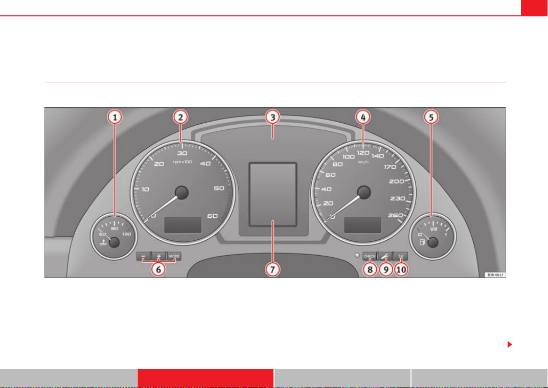
Cockpit 59
Safety First Operating Instructions Practical Tips Technical Specifications
Instruments
Instrument panel overview
The instrument panel is the driver's information centre.
Fig. 37 Overview of instrument panel
Coolant temperature gauge . . . . . . . . . . . . . . . . . . . . . . . . . . .
Rev counter incorporating digital clock and date . . . . . . . . . .
Warning and indicator lamps . . . . . . . . . . . . . . . . . . . . . . . . . .
Speedometer (incorporating odometer display) . . . . . . . . . . .
Fuel gauge . . . . . . . . . . . . . . . . . . . . . . . . . . . . . . . . . . . . . . . . .
Adjuster buttons for
− Digital clock and date . . . . . . . . . . . . . . . . . . . . . . . . . . . . .
− Instrument lighting . . . . . . . . . . . . . . . . . . . . . . . . . . . . . . . .
Digital display with
− Service interval display . . . . . . . . . . . . . . . . . . . . . . . . . . . .
A
1
60
A
2
61, 61
A
3
65
A
4
63
A
5
63
A
6
61
62
A
7
74
ExeoST_EN.book Seite 59 Freitag, 3. September 2010 11:41 11
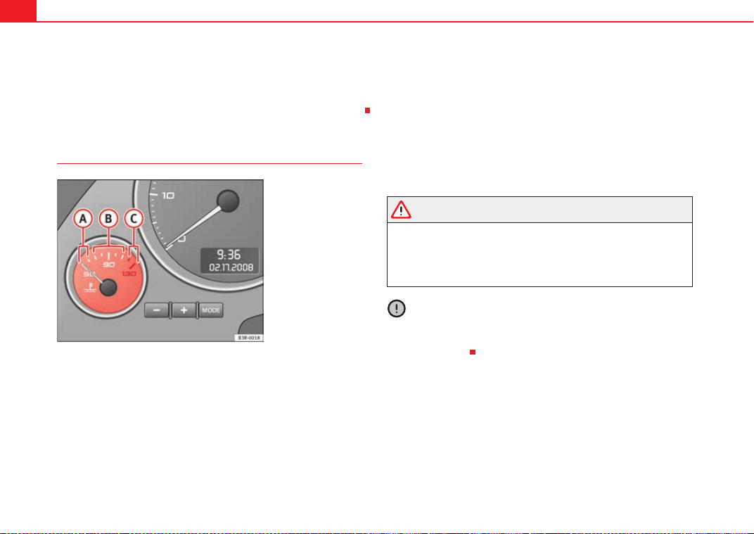
Cockpit60
− Driver information system . . . . . . . . . . . . . . . . . . . . . . . . . .
CHECK button . . . . . . . . . . . . . . . . . . . . . . . . . . . . . . . . . . . . . .
Call-up button for service indicator . . . . . . . . . . . . . . . . . . . . .
Reset button for trip recorder . . . . . . . . . . . . . . . . . . . . . . . . . .
Coolant temperature gauge
The coolant temperature gauge ⇒ fig. 38 only works when the ignition is
switched on. In order to avoid engine damage, please read the following
notes for the different temperature ranges.
Cold temperature
If the needle is still on the left of the dial, this indicates that the engine has
not yet reached operating temperature. Avoid high revs and heavy accelera-
tion and do not make the engine work hard.
Normal temperature
In normal operations, the needle will settle somewhere in the centre of the
dial once the engine has reached running temperature. The temperature may
also rise when the engine is working hard, especially at high outside temper-
atures. This is no cause for concern, provided the warning lamp
v does not
light up in the instrument panel.
Warning temperature
If the symbol
flashes in the display, this means that either the coolant
temperature is too high or the coolant level is too low ⇒ page 78.
WARNING
• Before opening the bonnet and checking the coolant level, observe the
warning information ⇒ page 229.
• Never open the bonnet when steam or coolant is being released from it.
This could lead to burns. Wait until you can no longer see or hear escaping
steam or coolant.
Caution
Accessories in front of the air inlet reduce the cooling effect of the coolant. At
high outside temperatures and high engine loads, there is a risk of the
engine overheating.
71
A
8
64
A
9
74
A
10
63
Fig. 38 Engine coolant
temperature gauge
A
A
A
B
A
C
ExeoST_EN.book Seite 60 Freitag, 3. September 2010 11:41 11
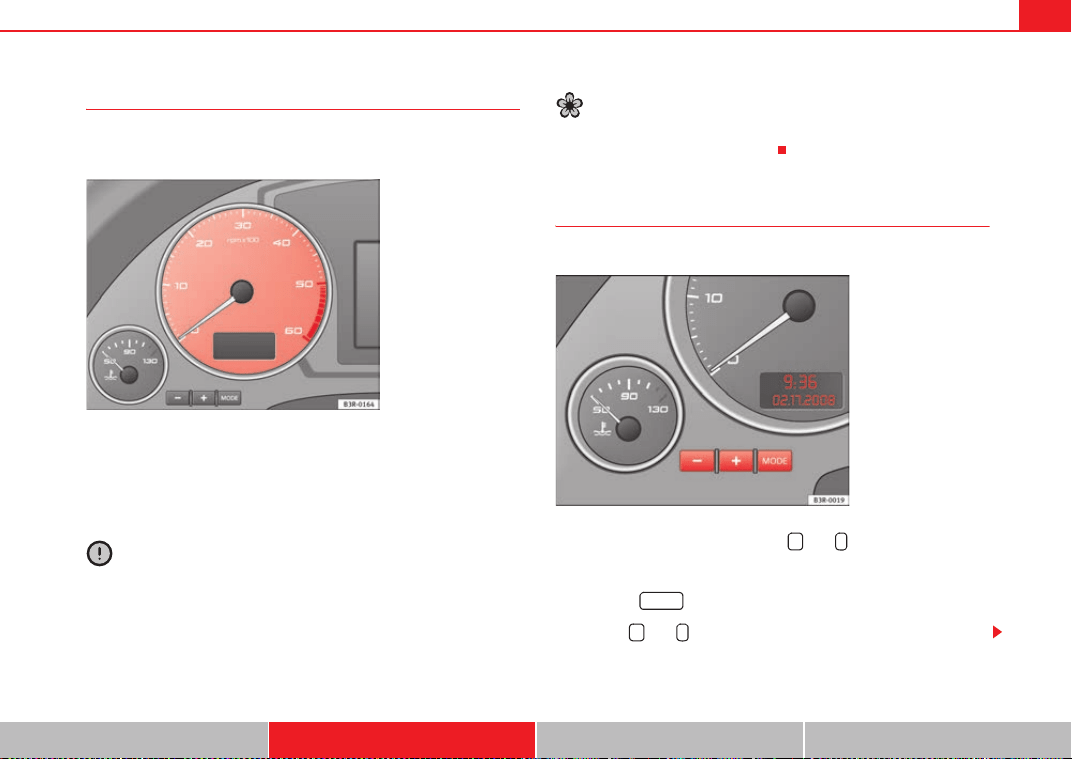
Cockpit 61
Safety First Operating Instructions Practical Tips Technical Specifications
Rev counter
The rev counter indicates the number of engine revolutions
per minute.
You should select a lower gear if the engine speed drops below 1500 rpm.
The start of the red zone on the dial indicates the maximum engine speed
which may be used when the engine is warm and after it has been run in prop-
erly. However, it is advisable to change up a gear or lift your foot off the accel-
erator before the needle reaches the red zone.
Caution
The rev counter needle ⇒ fig. 39 must only reach the red zone for a short
period, otherwise the engine could be damaged. The start of the red zone on
the dial is different for some engine versions.
For the sake of the environment
Changing up into higher gears early will help you to reduce fuel consumption,
emissions and minimise engine noise.
Digital clock and date
Your vehicle is equipped with a quartz clock.
The time and date are set using the and buttons.
Setting the hour
– Press the button. The hour display will start to flash.
– Use the and buttons to set the hour.
Fig. 39 Detailed view of
the instrument panel: Rev
counter
Fig. 40 Detailed view of
the instrument panel:
Digital clock
+ -
MODE
+ -
ExeoST_EN.book Seite 61 Freitag, 3. September 2010 11:41 11
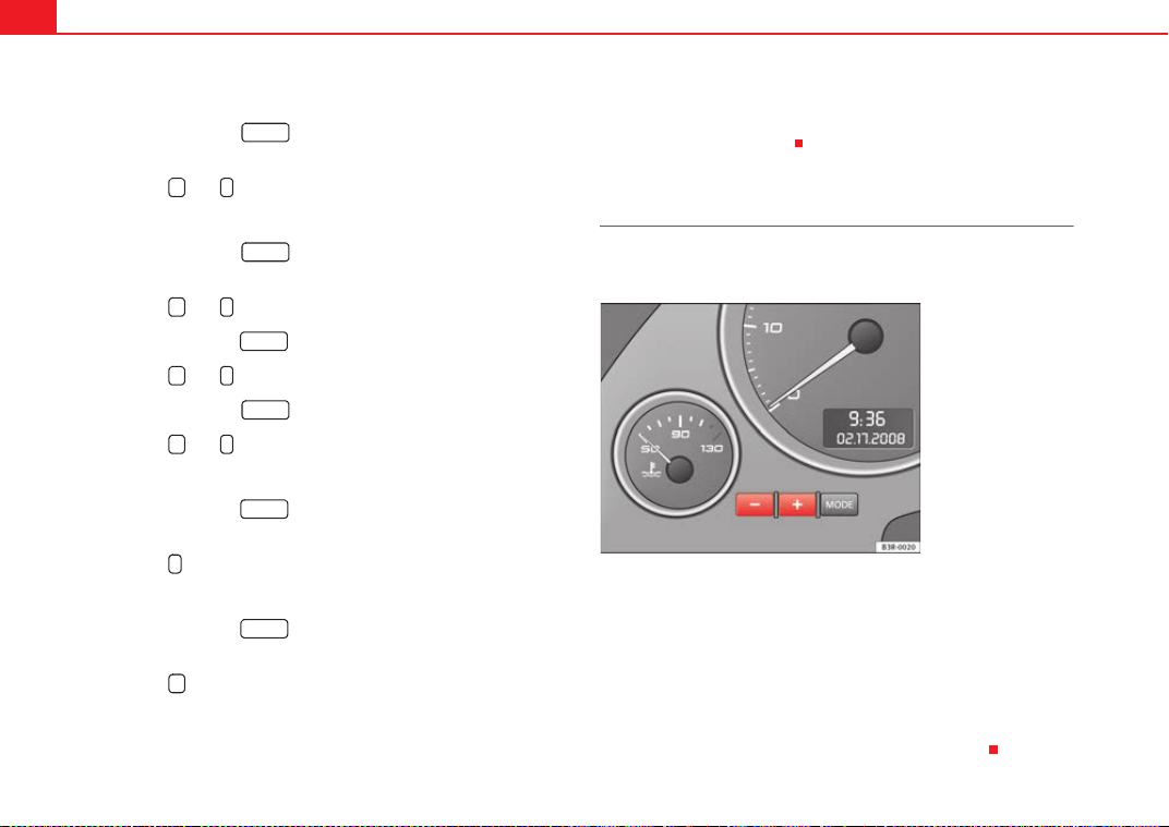
Cockpit62
Setting the minutes
– Keep pressing the button until the minutes display
flashes.
– Use the and buttons to set the minutes.
Setting the date
– Keep pressing the button until the date display (day)
flashes.
– Use the and buttons to set the day.
– Keep pressing the button until the month display flashes.
– Use the and buttons to set the month.
– Keep pressing the button until the year display flashes.
– Use the and buttons to set the year.
Deactivating the date display
– Keep pressing the button until the complete date display
flashes.
– Use the button to disable the date display.
Activating the date display
– Keep pressing the button until the complete date display
flashes.
– Use the button to enable the date display.
When the display stops flashing, this means the setting you are performing
is completed and the time and date have been successfully stored.
When the ignition is switched off, the odometer and the digital clock with
date display can be switched on for a few seconds by pressing the CHECK
button ⇒ page 59, fig. 37 .
Instrument lighting
The brightness of the instrument lighting can be adjusted as
required.
– Press the "+" button to increase the brightness of the instrument
lighting.
– Press the "-" button to reduce the brightness of the instrument
lighting.
The instrument lighting (dials and needles), the centre console illumination
and the illumination of the displays are regulated by a photodiode incorpo-
rated in the instrument panel, depending on the outside light.
MODE
+ -
MODE
+ -
MODE
+ -
MODE
+ -
MODE
-
MODE
+
A
8
Fig. 41 Instrument panel
lighting
ExeoST_EN.book Seite 62 Freitag, 3. September 2010 11:41 11
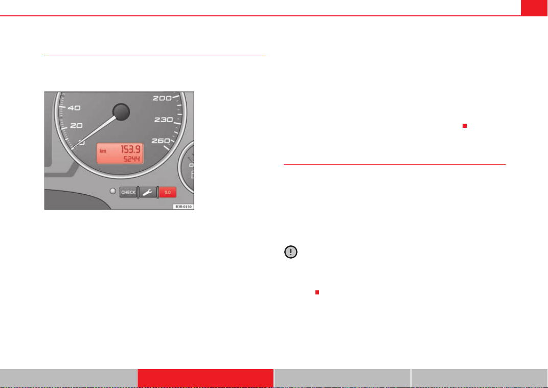
Cockpit 63
Safety First Operating Instructions Practical Tips Technical Specifications
Speedometer with odometer
The speedometer indicates the speed of the vehicle and the
distance travelled.
The distance is normally stated in kilometres (km). On some models,
however, the odometer will show “miles”.
Lower odometer
The lower odometer records the vehicle's total mileage.
Upper odometer (trip recorder)
The upper odometer shows the distance that has been travelled since the trip
recorder was last reset. It is used to measure short trips. The last digit of the
trip recorder indicates distances of 100 metres or tenths of a mile. The upper
odometer can be reset to zero by pressing the reset button ⇒ fig. 42.
Fault display
If there is a fault in the instrument panel, the letters DEF will appear perma-
nently in the trip recorder display. Please have the fault repaired as soon as
possible.
Electronic immobiliser
The vehicle key data is consulted when the ignition is switched on.
If an uncoded key is used, the message SAFE will appear in the trip recorder
display. The vehicle can no longer be started if that happens.
Fuel reserve
The display only works when the ignition is switched on.
When the needle reaches the reserve zone, the symbol
lights up in the
instrument panel display ⇒ page 80. At this point there are still about 8 to 10
litres of fuel left in the tank. This is your reminder to fill up soon.
You can consult the tank capacity of your vehicle in the ⇒ page 311, “Dimen-
sions and capacities” section.
Caution
Never run the tank completely dry. If there is an irregular fuel supply, misfiring
can occur. This means that fuel could reach the exhaust system without
burning. This may lead to the catalytic converter reheating and being
damaged.
Fig. 42 Detailed view of
the instrument panel:
Odometer
ExeoST_EN.book Seite 63 Freitag, 3. September 2010 11:41 11
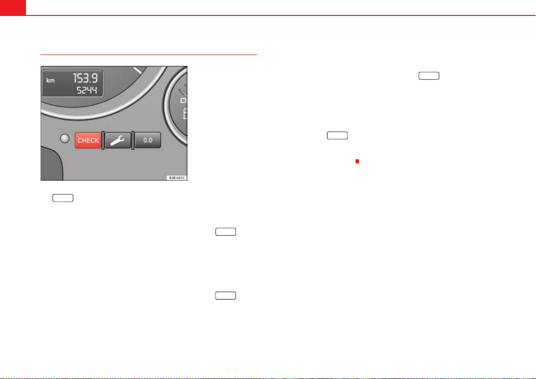
Cockpit64
CHECK button
The button has the following functions:
Activating the digital clock and the odometer
When the ignition is switched off, the odometer and the digital clock with
date display can be enabled for a few seconds by pressing the button
⇒ fig. 43.
Starting check procedure (auto-check control)
The auto-check control ⇒ page 75 checks important components and vehicle
systems. These background checks are run constantly, as long as the ignition
is switched on.
You can start the “check procedure” manually by pressing the button
with the ignition switched on. This function check can be started with the
engine either switched off or running, but not at road speeds above 5 km/h.
Calling up driver messages
If a Priority 1 symbol flashes in the display ⇒ page 75, or if the bulb monitor
detects a failure of one of the lights ⇒ page 82, the relevant driver informa-
tion can be called up again by briefly pressing the button. For
example:
Switch off engine, check oil level
The message will disappear from the display after about 5 seconds.
Setting the speed warning
You can press the button to set speed limit warning 1 ⇒ page 83,
“Setting speed limit warning 1” while the vehicle is moving. Speed limit
warning 2* ⇒ page 84, “Setting speed limit warning 2” can only be set when
the ignition is switched off.
Fig. 43 Detailed view of
the instrument panel:
CHECK button
CHECK
CHECK
CHECK
CHECK
CHECK
ExeoST_EN.book Seite 64 Freitag, 3. September 2010 11:41 11
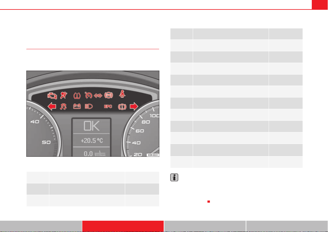
Cockpit 65
Safety First Operating Instructions Practical Tips Technical Specifications
Warning and indicator lamps
General description
The warning and indicator lamps indicate a number of
different functions and possible faults.
Fig. 44 Instrument panel with warning and indicator lamps
Note
A number of functions are monitored by the auto-check control ⇒ page 75. If
a malfunction should occur, this will be shown by the display in the instru-
ment panel either with a red symbol (priority 1 - danger) or a yellow symbol
(priority 2 - warning).
Exhaust emission control system ⇒ page 66
T
Airbag system ⇒ page 66
~
Tyre pressure too low ⇒ page 66
Cruise control ⇒ page 67
Trailer turn signals ⇒ page 67
J
Anti-lock brake system (ABS) ⇒ page 67
h
Seat belt warning ⇒ page 68
Left turn signals ⇒ page 68
!
Electronic Stability Programme (ESP) ⇒ page 68
F
Alternator ⇒ page 69
Main beam headlights ⇒ page 69
%0#
Engine management (alternative to D)
⇒ page 69
D
Glow plug system (alternative to %0#)
⇒ page 70
H
Fault in brake system / handbrake is
applied
⇒ page 70
Right turn signals ⇒ page 68
ExeoST_EN.book Seite 65 Freitag, 3. September 2010 11:41 11
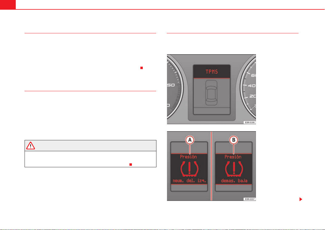
Cockpit66
Exhaust emission control system
If the warning lamp lights up continuously you should take your vehicle to a
specialised workshop as soon as possible in order to have the fault repaired.
If the warning lamp flashes drive on at reduced speed and seek professional
help in order to avoid damage to the catalytic converter.
For further information on the catalytic converter, see ⇒ page 198.
Airbag system T
This warning lamp monitors the airbag and belt tension
device system.
The warning lamp Tshould light up for a few seconds when the ignition is
switched on.
If the warning lamp does not go out, or if it lights up, flashes or flickers when
the vehicle is moving, this indicates a malfunction in the system.
WARNING
If a malfunction should occur, have the system checked immediately by a
qualified workshop. Otherwise there is a risk that the airbag system
and/or belt tensioners may not be triggered in an accident.
Tyre pressure warning lamp* ~
The tyre pressure should be corrected as soon as possible if
it is too low.
Fig. 45 Display: system
fault
Fig. 46 Display: warning
message
ExeoST_EN.book Seite 66 Freitag, 3. September 2010 11:41 11

Cockpit 67
Safety First Operating Instructions Practical Tips Technical Specifications
The yellow warning ~ lamp remains on if the system is faulty or if
the pressure is too low in at least one tyre. In the event of a system
fault, the letters TPMS are displayed in the centre of the instrument
panel ⇒ page 66, fig. 45. If the tyre pressure drops rapidly,
message ⇒ page 66, fig. 46 will be shown on the central display
of the instrument panel. If the pressure loss is more gradual,
message ⇒ page 66, fig. 46 will be shown on the central display
of the instrument panel. This message does not show the tyre
affected. Should any of these warnings be displayed:
–Stop the vehicle.
– Check the tyres. Although the warning corresponds to just one
tyre, you should also check the others.
– Correct the tyre pressure ⇒ page 246.
For more detailed information on the tyre pressure monitoring system, please
refer to ⇒ page 245.
Cruise control system*
The indicator lamp on the instrument panel lights up when the cruise
control system is operating.
Trailer turn signals*
This turn signal lamp flashes when the turn signals are oper-
ating while towing a caravan or trailer.
The turn signal lamp flashes when the turn signals are operated if a trailer
is correctly coupled to the vehicle.
Where a turn signal bulb does not work, either on the trailer or on the towing
vehicle, the turn signal bulb will not flash.
Anti-lock brake system (ABS) J
The warning lamp monitors the ABS and the integrated elec-
tronic differential lock (EDL).
The warning lamp J lights up for a few seconds when the ignition is
switched on and while the engine is being started. The lamp goes out again
after the system has run through an automatic test sequence.
There is a fault in the ABS if:
• The warning lamp does not light up when the ignition is switched on
• The warning lamp does not go out again after a few seconds
• The warning lamp lights up when the vehicle is moving
The vehicle can still brake in the normal way (except that the ABS control func-
tion is out of action). Please take the vehicle to a qualified workshop as soon
as possible. For further information on the ABS, see ⇒ page 192.
If a malfunction should occur in the ABS, the ESP warning lamp will also light
up.
A
A
A
B
ExeoST_EN.book Seite 67 Freitag, 3. September 2010 11:41 11
Cockpit68
Entire brake system fault
If the ABS warning lamp
J lights up together with the brake warning lamp
H ⇒ page 70 (with the handbrake released), this indicates not only a fault
in the ABS function, but probably also a malfunction in the main brake system
⇒ .
The symbol
H will light up in the instrument panel if a fault occurs in the
brake system. Please refer to ⇒ page 77.
Electronic differential lock (EDL) fault
The EDL works in conjunction with the ABS. The ABS indicator lamp will light
up
J to indicate an EDL fault. Please take the vehicle to a qualified workshop
as soon as possible. For further information on the EDL, see ⇒ page 193.
WARNING
• Before opening the bonnet and checking the brake fluid level, observe
the warning information in ⇒ page 229, “Work in the engine compart-
ment”.
• If the brake warning lamp H should light up together with the ABS
warning lamp
J, stop the vehicle immediately and check the brake fluid
level in the reservoir. If the fluid level has dropped below the "MIN" mark
you must not drive on, as there is a risk of accident. Obtain technical assist-
ance.
• If the brake fluid level is correct, the fault in the brake system may have
been caused by a fault in the ABS control function. As a result, the rear
wheels can lock relatively easily when braking. Under certain circum-
stances, the rear of the vehicle could suddenly sway from side to side, with
the subsequent danger of skidding. Drive carefully to the nearest special-
ised workshop and have the fault repaired.
Seat belt warning lamp* h
The warning lamp acts as a reminder to the driver to fasten
the seat belt.
After switching on the ignition, the warning lamp will remain lit until the
driver and front passenger (if applicable) have fastened their seat belts.
When the vehicle has reached a certain speed, you will also hear a warning
signal and the warning light will flash.
For further information on the seat belts, see ⇒ page 22.
Turn signals and hazard warning lights
Depending on which turn signal is operated, either the left or right turn
signal lamp flashes. Both turn signal lamps will flash when the hazard
warning lights are switched on.
If a turn signal fails, the indicator lamp will start flashing twice as fast as
normal.
This does not apply when towing a trailer. Where a turn signal bulb does not
work, either on the trailer or on the towing vehicle, the turn signal bulb will
not flash. For further information on the turn signals, see ⇒ page 123.
Electronic Stability Programme !
This warning lamp monitors the Electronic Stability
Programme (ESP).
The warning lamp ! has the following functions:
ExeoST_EN.book Seite 68 Freitag, 3. September 2010 11:41 11
Cockpit 69
Safety First Operating Instructions Practical Tips Technical Specifications
• It will start flashing to indicate that ESP is counteracting an unstable
driving condition.
• It lights up when the ignition is switched on for approx. 2 seconds while
the function is checked.
• The warning lamp will light up if there is a malfunction in the ESP.
• It will light up after the battery has been disconnected.
• The warning lamp will light up if the ESP is switched off.
• It will also come on if a fault should occur in the ABS because the ESP
operates in conjunction with the ABS.
If the ESP warning lamp lights up and stays on after the engine is started, this
may mean that the control system has temporarily switched off the ESP. In this
case the ESP can be reactivated by switching the ignition off and then on
again. After this the warning lamp should go out to show that the system is
fully functional.
The warning lamp will light up when the ignition is switched on if the battery
has been disconnected and then reconnected. It should go out again after
driving a short distance if the steering wheel is turned slightly.
For further information on the ESP, see ⇒ page 193.
Alternator F
The warning lamp signals a fault in the alternator or in the
vehicle's electrical system.
The warning lamp F lights up when the ignition is switched on. It should
switch off after the engine has started.
If the warning lamp
F lights up when you are driving, you can normally
continue as far as the nearest qualified workshop. However, given that the
battery will be running down, any electrical consumption not absolutely vital
should be switched off.
Caution
If the coolant warning lamp v in the instrument panel lights up as well as the
alternator waning lamp while driving ⇒ page 78, stop the vehicle immedi-
ately and switch off the engine. In this case the coolant pump is no longer
working, and there is a risk of engine damage.
Main beam headlights
The indicator lamp lights up when the main beams are on or when the
headlight flasher is operated.
For further information on the main beam headlights, see ⇒ page 123.
Engine management %0#
This warning lamp monitors the engine management system
for petrol engines.
The warning lamp %0# (Electronic Power Control) lights up while the function
is being checked.
Note
If the warning lamp lights up while the vehicle is moving, this indicates a fault
in the engine management system. The vehicle must be taken immediately to
a qualified workshop to have the engine serviced.
ExeoST_EN.book Seite 69 Freitag, 3. September 2010 11:41 11
Cockpit70
Glow plug system D
The indicator lamp lights up while the glow plugs are
preheating.
The indicator lamp D lights up while the glow plugs are preheating. When
the indicator lamp goes out the engine should be started straight away. When
the engine is warm, or at outside temperatures above +8 °C, the warning
lamp will only light up very briefly.
Note
• If the glow plug indicator lamp should start flashing while the vehicle is
moving, this indicates a fault in the engine management system. The engine
should be serviced without delay.
• If the indicator lamp fails to light up when the ignition is switched on, this
can mean that the glow plug system is defective. The engine should be
serviced.
Brake system H
The warning lamp flashes when the handbrake is applied, or
if the brake fluid level is too low or if there is a fault in the ABS
system.
If the warning lamp H flashes (and the handbrake is not applied), stop the
vehicle and check the brake fluid level ⇒ ⇒ page 240.
If a failure should occur in the ABS, the ABS warning lamp
J will light up
together with the brake warning lamp
H ⇒ .
Handbrake on
The warning lamp
H also lights up when the handbrake is applied. In addi-
tion to this, the handbrake warning ⇒ page 76 switches on after driving for 3
seconds at a speed above 5 km/h.
WARNING
• Before opening the bonnet and checking the brake fluid level, observe
the warning information in ⇒ page 229, “Work in the engine compart-
ment”.
• If the brake warning lamp does not go out, or if it lights up when
driving, the brake fluid level in the reservoir is too low and this may cause
an increased accident risk. Stop the vehicle and do not drive on. Obtain
technical assistance.
• If the brake warning lamp lights up together with the ABS warning
lamp, this can mean that there is a fault in the ABS control function. As a
result, the rear wheels can lock relatively easily when braking. Under
certain circumstances, the rear of the vehicle could suddenly sway from
side to side, with the subsequent danger of skidding. Drive carefully to the
nearest specialised workshop and have the fault repaired.
ExeoST_EN.book Seite 70 Freitag, 3. September 2010 11:41 11
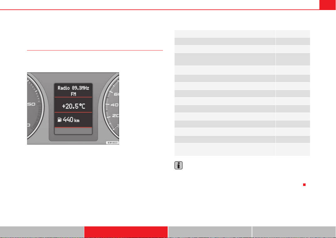
Cockpit 71
Safety First Operating Instructions Practical Tips Technical Specifications
Driver information system
General notes
The driver information system in the instrument panel shows
the status of various on-board systems at a glance.
The display for the driver information system is in the centre of the instrument
panel.
The system runs a check on certain components and functions when the igni-
tion is switched on and while the vehicle is moving. The DIS system gives an
audible warning if a fault should occur or if servicing is required, and a red or
yellow warning symbol (in some cases with a corresponding driver message)
appears in the instrument panel display.
The driver is informed on the audio system.
The driver information system includes the following functions:
Note
• If a fault should occur, the display will show a red or yellow warning
symbol. A red warning symbol indicates a serious malfunction ⇒ page 77. A
yellow warning symbol indicates a less serious malfunction ⇒ page 79.
Fig. 47 Cockpit: Digital
instrument panel display
CD player, radio and telephone display* ⇒ page 72
Outside temperature display ⇒ page 72
Gear indicator* ⇒ page 73
Selector lever positions for the 7-speed automatic gear-
box*
⇒ page 189
Selector lever positions with multitronic
®
*
⇒ page 185
Distance to empty ⇒ page 73
Door and tailgate warning ⇒ page 74
Service indicator ⇒ page 74
auto-check control ⇒ page 75
Driving tips ⇒ page 76
Handbrake warning ⇒ page 76
Bulb monitor* ⇒ page 82
Onboard computer* ⇒ page 85
Tyre pressure monitoring* ⇒ page 89
Navigation information* Separate Instruc-
tion Manual
ExeoST_EN.book Seite 71 Freitag, 3. September 2010 11:41 11
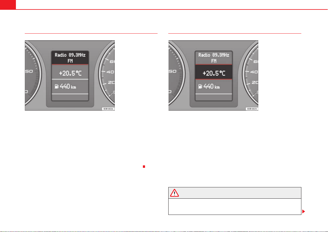
Cockpit72
CD, radio and telephone* display
If the radio is switched on and no Priority 2 faults are indicated by the auto-
check control, depending on the type of radio fitted, the display will show the
name or frequency of the selected radio station and complementary informa-
tion, once the “OK” symbol has gone out.
When in CD mode*, the display will show the current track.
If you have a compatible telephone*, the phone book or telephone dialled
can also be seen on this display.
These displays appear in addition to the display on the radio itself.
Outside temperature display
The outside temperature is shown in the display when the ignition is switched
on ⇒ fig. 49. In vehicles with an automatic gearbox, the display does not
appear until the driver has engaged a gear.
At temperatures below +5 °C a snowflake symbol appears next to the temper-
ature display. This is to warn the driver to take extra care when there is a risk
of ice on the road. When the vehicle is stationary or travelling at very low
speeds, the temperature displayed may be slightly higher than the actual
ambient temperature as a result of heat coming from the engine.
If the vehicle has an air conditioner and the display is changed over to °F
(degrees Fahrenheit), the outside temperature display automatically changes
over to °F ⇒ page 167.
WARNING
Do not rely on the outside temperature display as an ice warning. Please
bear in mind that there may be ice on the roads even at outside tempera-
tures of +5 °C – beware of ice patches.
Fig. 48 Display: addi-
tional radio information
Fig. 49 Display: Outside
temperature display
ExeoST_EN.book Seite 72 Freitag, 3. September 2010 11:41 11
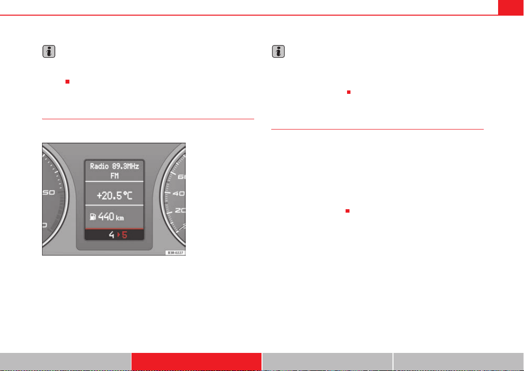
Cockpit 73
Safety First Operating Instructions Practical Tips Technical Specifications
Note
When the display shows route guidance instructions from the navigation
system, the outside temperature appears in the second line of the radio
display.
Gear display*
This display helps to save fuel.
Use the gear display to save fuel. The display ⇒ fig. 50 on the instrument
panel recommends that you select the gear indicated by the arrow. It may
also skip a gear, and recommend changing up from 4th gear to 6th gear, for
example.
Note
• The display may not recommend any gear-change while you are acceler-
ating.
• If desired, you can have the gear-change display deactivated by an
Authorised Service Centre.
Distance to empty
The distance to empty display can help you to plan your trip.
The estimated distance to empty is displayed in km. It shows how far the
vehicle can be driven with the amount of fuel left in the tank, assuming the
same style of driving. The distance to empty is displayed in increments of 10
km.
The distance to empty is calculated on the basis of the fuel consumption over
the last 30 kilometres. The distance to empty will increase if you drive in a
more economical manner.
Fig. 50 Gear display
ExeoST_EN.book Seite 73 Freitag, 3. September 2010 11:41 11
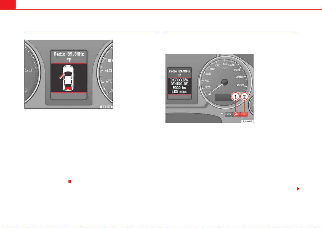
Cockpit74
Door and tailgate warning
The door and tailgate warning symbol lights up if one or more of the doors, or
the bonnet or tailgate are not properly closed when the ignition is on. The
symbol also indicates which of these is not properly closed. The display in the
illustration ⇒ fig. 51 shows that the driver door is open.
The corresponding part of the pictogram will flash if either the bonnet or tail-
gate are open. The warning symbol goes out when the bonnet, tailgate and
all the doors are closed.
In vehicles with a driver information system and an onboard computer* the
door catches/tailgate warning symbol can be switched off by briefly pressing
one of the control switches for the onboard computer ⇒ page 86. However,
the warning symbol will appear again if any of the doors or the bonnet or tail-
gate is opened or closed.
Service indicator
This display reminds the driver when the next routine service
is due.
Displaying distance to next service
When you press the service button briefly with the ignition switched on,
the display will show how far the vehicle can be driven before the next service
is due. This check can be carried out with the engine stopped or running up
to 5 km/h. Before the first 500 km and after the ignition cycle, the kilometres
and days before the service inspection are not displayed.
If the service button is pressed before the first 500 km the following indi-
cation appears on screen:
Service in ----- km --- days
This is also valid for vehicles with “LongLife Service Intervals”*.
Fig. 51 Display: Door and
tailgate warning
Fig. 52 Detailed view of
the instrument panel:
Service indicator
A
1
A
1
ExeoST_EN.book Seite 74 Freitag, 3. September 2010 11:41 11
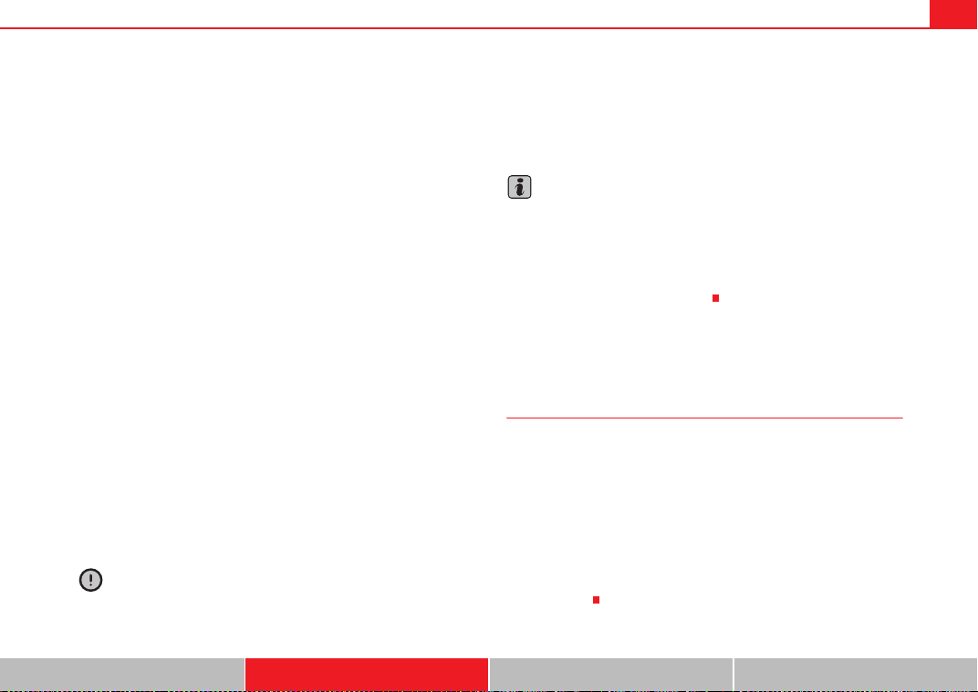
Cockpit 75
Safety First Operating Instructions Practical Tips Technical Specifications
Service reminder
The instrument panel controls the distance travelled every day. It calculates
the average of these distances travelled and activates the service reminder
sufficiently in advance.
The display reverts back to the standard display after about 5 seconds. The
remaining distance to the next service is updated every time the ignition is
switched on, until the service becomes due.
Service due
When a service is due, SERVICE! will appear in the display immediately after
you switch on the ignition. The display reverts back to the standard display
after about 5 seconds.
Resetting the display
The display is reset by the workshop after the service has been carried out.
The service interval will be set to a LongLife Service (flexible service interval)
or Inspection Service (fixed service interval), depending on which engine oil
is used. It is only possible to reset the display via the instrument panel when
an oil change is performed; in this case the display can only be reset to a fixed
service interval of 15,000 km. Proceed as follows:
• Switch the ignition off.
• Press the service button ⇒ page 74, fig. 52 and hold while switching
on the ignition. The display will show one of these messages:
Service in ----- km or Service!
• Now press and hold the reset button until the display shows
Service in ----- km --- days or Service!
The display switches out of the reset mode if you do not press the reset button
within 5 seconds.
Caution
The system cannot calculate the figures for the service interval display if the
battery is disconnected from the vehicle, so no service reminder can be
displayed during this time. Please remember that it is essential to service the
vehicle within the established time limits to prevent its deterioration and to
extend its useful life (particularly that of the engine). The period between two
services must never be longer than the time specified in the Maintenance
Programme, even if you only cover a low mileage during this time.
Note
• Do not reset the service indicator between services, otherwise the display
will be incorrect.
• The information in the service indicator remains intact if the battery is
disconnected.
• The distance to the next service cannot be called up if the system has
detected a Priority 1 fault (red symbol).
Auto-check system
Introduction
The auto-check system checks important components and vehicle systems.
These background checks are run constantly, as long as the ignition is
switched on.
A message is displayed on the instrument panel if a fault should occur or if
any maintenance or repairs are urgently required. This is accompanied by an
audible warning signal. Depending on the priority of the fault, a red or yellow
warning symbol lights up on the display.
The red symbol indicates danger, whereas the yellow one represents a
warning. Additional messages for the driver may be shown with the red or
yellow symbols.
A
1
A
2
ExeoST_EN.book Seite 75 Freitag, 3. September 2010 11:41 11
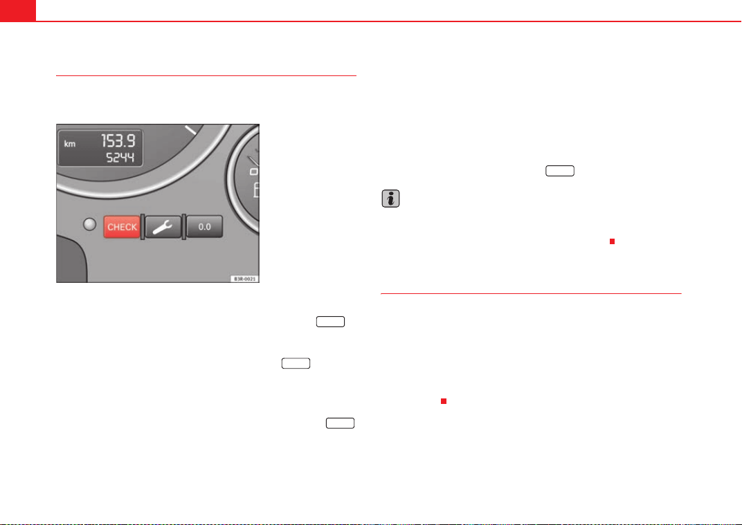
Cockpit76
Driver messages
Additional messages for the driver are displayed together
with the warning symbols on the instrument panel.
Driver messages and red symbols
If a red warning symbol appears on the display, you can press the
button ⇒ fig. 53 to call up an additional driver message.
For example: in the event of an oil pressure malfunction, the oil pressure
symbol
E will appear in the display. If you now press the button, the
following message will appear in the display:
Switch off engine, check oil level
The message will disappear from the display after about 5 seconds. If
required, the message can be called up again by briefly pressing the
button.
Driver messages and yellow symbols
If a yellow warning symbol appears in the display, it will automatically be
accompanied by the corresponding driver message.
For example, the symbol
is displayed to indicate that the windscreen
washer fluid level is low. In addition, the following message will appear:
Top up washer fluid
The message will disappear after a few seconds. If required, the message can
be called up again by briefly pressing the button.
Note
• The messages handbrake on and when stationary apply footbrake to
select gear cannot be called up a second time. They will remain in the display
until the handbrake is released or until a gear is selected.
Handbrake warning
– Release the handbrake.
If you drive by mistake with the handbrake still applied, you will hear a
warning buzzer and the display will show the message:
Handbrake on
The handbrake warning switches on after driving for 3 seconds at speeds
above 5 km/h.
Fig. 53 Instrument panel:
CHECK button
CHECK
CHECK
CHECK
CHECK
ExeoST_EN.book Seite 76 Freitag, 3. September 2010 11:41 11
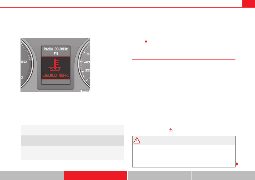
Cockpit 77
Safety First Operating Instructions Practical Tips Technical Specifications
Red symbols
A red symbol warns of a danger.
–Stop the vehicle.
– Switch the engine off.
– Check the fault. Obtain professional assistance if necessary.
The red symbols are used to indicate a Priority 1 fault (serious malfunction).
A red symbol is accompanied by three warning chimes. The symbols will keep
flashing until the faults are corrected. If several Priority 1 faults are detected
at the same time, the symbols are displayed one after the other for about 2
seconds.
Fault in the brake system H
A fault in the brake system should be repaired as soon as
possible.
If the symbol H flashes in the display, there is a fault in the brake
system. One of the following messages will appear in the display
together with the symbol:
Stop vehicle, check brake fluid and hydraulic fluid levels
Warning! Fault in brake system (ABS) Take vehicle to workshop
–Stop the vehicle.
– Check the brake fluid level ⇒ page 240.
If the ABS fails, the ABS warning lamp J will light up together with the brake
system fault symbol
H ⇒ .
WARNING
• Before opening the bonnet and checking the brake fluid level, observe
the warning information in ⇒ page 229, “Work in the engine compart-
ment”.
• If the brake fluid level in the reservoir is too low, this could result in an
accident. Do not drive on! Obtain technical assistance.
H
BRAKES
Fault in brake system ⇒ page 77
COOLANT
Coolant level too low / coolant tem-
perature too high
⇒ page 78
E
OIL
PRESSURE
Engine oil pressure too low ⇒ page 78
Fig. 54 Display: Coolant
level warning
ExeoST_EN.book Seite 77 Freitag, 3. September 2010 11:41 11
Cockpit78
• If the brake warning lamp lights up together with the ABS warning
lamp, this can mean that there is a fault in the ABS control function. As a
result, the rear wheels can lock relatively easily when braking. Under
certain circumstances, the rear of the vehicle could suddenly sway from
side to side, with the subsequent danger of skidding. Drive carefully to the
nearest specialised workshop and have the fault repaired.
Fault in the cooling system
Faults in the cooling system must be repaired immediately.
If the symbol flashes in the display, this means that either the
coolant temperature is too high or the coolant level is too low. The
following message will appear in the display together with the
symbol:
Switch off engine and check coolant level
– Stop the vehicle.
– Switch the engine off.
– Check the coolant level ⇒ page 234.
– Add more coolant if necessary ⇒ page 235.
– Wait for the symbol to go out before driving on.
– Obtain professional assistance if necessary.
If the coolant level is correct, the overheating may be caused by a malfunction
of the radiator fan.
If the alternator warning lamp lights up as well ⇒ page 69, it is possible that
the drive belt has broken.
Caution
Do not drive on if the symbol v has come on to indicate a fault in the cooling
system, otherwise there is a risk of engine damage.
Engine oil pressure too low E
If the engine oil pressure is too low the fault must be repaired
immediately.
If the E symbol flashes in the display, the oil pressure is too low.
The following message will appear in the display together with the
symbol:
Switch off engine, check oil level
– Stop the vehicle.
– Switch the engine off.
– Check the engine oil level ⇒ page 232.
– Obtain professional assistance if necessary.
Engine oil level too low
If the engine oil level is too low, add more oil ⇒ page 233.
Engine oil level correct
If the
E symbol flashes and the engine oil level is correct, obtain profes-
sional assistance. Do not drive on! Do not continue to run the engine, even at
idle speed.
WARNING (continued)
ExeoST_EN.book Seite 78 Freitag, 3. September 2010 11:41 11
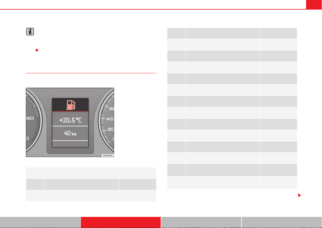
Cockpit 79
Safety First Operating Instructions Practical Tips Technical Specifications
Note
The oil pressure warning lamp E is not an indicator for the oil level. The oil
level should therefore be checked regularly, preferably every time you fill the
tank.
Yellow symbols
A yellow symbol indicates a warning.
Yellow symbols are used to indicate a Priority 2 fault (warning).
Brake light failure warning light ⇒ page 80
Fuel level low ⇒ page 80
X
Engine speed governing ⇒ page 80
F ig. 55 D isp la y: Fu el le ve l
low
Check engine oil level ⇒ page 80
Engine oil sensor faulty* ⇒ page 80
Diesel particulate filter* obstructed ⇒ page 80
Photosensor/rain sensor faulty ⇒ page 81
I
Brake pad worn ⇒ page 81
Speed warning 1 ⇒ page 81
Dynamic headlight range control* faulty ⇒ page 81
Adaptive headlights* faulty ⇒ page 81
Washer fluid level low* ⇒ page 81
Speed warning 2* ⇒ page 81
F
Battery voltage too high or too low* ⇒ page 81
Bulb monitor* ⇒ page 82
~
Tyre pressure monitoring system*
Loss of pressure
⇒ page 89
TPMS Tyre pressure monitoring system*
System not available
⇒ page 66
ExeoST_EN.book Seite 79 Freitag, 3. September 2010 11:41 11
Cockpit80
Yellow symbols are accompanied by one warning buzzer. The function indi-
cated should be checked as soon as possible. If several Priority 2 faults are
detected at the same time, the symbols are displayed one after the other for
about 2 seconds at a time.
Brake light failure
This warning light will appear on the upper part of the display if any of the
brake lights has failed. A text message in the central part of the display indi-
cates which brake light has failed (left or right).
Fuel level low
When this symbol comes on for the first time, there are about 8 to 10 litres
of fuel left in the tank. You should fill up as soon as possible ⇒ page 225.
Engine speed governing X
Max. engine speed XXXX rpm
There is a fault in the engine management. In addition, the warning lamp
%0#
on the instrument panel will light up. The engine speed will be governed to
the speed displayed in the driver information system. Please ensure that the
engine speed does not exceed the speed shown (for example, when
changing down a gear).
Take the vehicle to a qualified workshop immediately to have the fault
repaired.
Check engine oil level
If the symbol lights up, please check the engine oil level as soon as
possible⇒ page 232. Top up the oil at the next opportunity ⇒ page 233.
Engine oil sensor defective *
If the symbol lights up, take the vehicle to a qualified workshop and have
the oil level sensor checked. Until then it is advisable to check the oil level
every time you fill up with fuel ⇒ page 232.
Diesel particulate filter obstructed
If the symbol lights up, you can contribute towards automatic filter
cleaning by driving in the right manner. To do this, drive about 15 minutes in
4th or 5th gear (automatic gearbox: S gear range) at a speed of 60 km/h, with
the engine running at approximately 2000 rpm. The increase in temperature
will burn off any soot in the filter. When cleaning is successful, the symbol
switches off.
If the symbol
does not turn off, or the three lamps turn on (particulate
filter
, emission control system fault and heaters D), take the vehicle
to a qualified workshop to repair the fault.
For further information on the diesel particulate filter, see ⇒ page 199.
WARNING
It is essential that you adjust your speed to suit the weather, road, terrain
and traffic conditions. The recommended driving speed must never lead to
the driver disregarding the traffic regulations.
ExeoST_EN.book Seite 80 Freitag, 3. September 2010 11:41 11
Cockpit 81
Safety First Operating Instructions Practical Tips Technical Specifications
Photosensor/rain sensor faulty
Automatic headlights / automatic wipers faulty
If the
symbol ligh ts up, this means that the photosensor/rain sensor is not
working. For safety reasons, the dipped beam headlights will then be
switched on permanently when the light switch is set to the AUTO position.
However, you can still switch the lights on and off in the normal way with the
light switch. If the rain sensor is faulty, the functions operated via the wind-
screen wiper lever will still be available. You should have the photo-
sensor/rain sensor checked by a specialised workshop as soon as
possible.
Worn brake pads I
If the I symbol lights up, have the front brake pads (and, for safety reasons,
the rear pads as well) inspected by a qualified workshop.
Speed warning 1
If the symbol lights up, this means you are exceeding the speed that has
been pre-set with the speed warning function. You should reduce your speed
accordingly ⇒ page 82.
Headlight range control faulty
This symbol indicates a malfunction in the dynamic headlight range
control. Take the vehicle to a qualified workshop to have the dynamic head-
light range control function repaired.
Adaptive headlights* faulty
Adaptive headlights faulty
This symbol
indicates that the adaptive headlight system is faulty. Take
the vehicle to a qualified workshop to have the headlights or the adaptive
headlight control unit repaired.
Washer fluid level low
If the symbol lights up, top up the fluid for the windscreen washer and
headlight washer system* ⇒ page 236.
Speed warning 2
If the symbol lights up, this means you are exceeding the speed that has
been pre-set. You should reduce your speed accordingly ⇒ page 82.
Battery voltage too high or too low F
If the F symbol lights up, take the vehicle to a qualified workshop and have
the following items checked:
• Poly V-belt
• Battery condition
It is also advisable to check whether the alternator warning lamp has come on
⇒ page 69.
ExeoST_EN.book Seite 81 Freitag, 3. September 2010 11:41 11
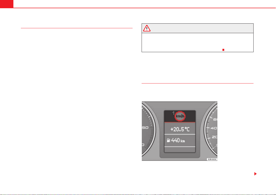
Cockpit82
Bulb monitor
The bulb monitor checks whether the lights on the vehicle are
working.
If a defective bulb is detected, or if one of the lights has failed for any reason,
the bulb monitor symbol
will appear in the display together with an addi-
tional message (which goes out after 5 seconds). For instance, if the rear left
turn signal is not working, the display in the instrument panel will show the
following message:
Left rear turn signal
The message disappears after 5 seconds. Press the CHECK button briefly if
you wish to call up the message again.
If the display indicates that one of the lights is not working, this can have a
number of causes:
• Bulb failure ⇒ page 267.
• A blown fuse ⇒ page 265, “Changing fuses”.
• Faulty electrical wiring.
It is not necessary to have lamps replaced in a specialised workshop,
however the use of Xenon lamps is recommended.
LED lamps
If any of the LED (Light Emitting Diode) functions fail, the complete lamp
should be replaced.
The failure of the lamp is only shown when the LED function goes out
completely. Sometimes, a LED will stop working, without displaying the
warning as the function continues to operate.
WARNING
• Bulbs are highly sensitive to pressure. The glass can break when you
touch the bulb, causing injury.
• The high voltage element of gas discharge bulbs* (xenon light) must be
handled correctly. Otherwise, there is a risk of death.
Speed warning*
Introduction
The speed warning function can help prevent you exceeding
a particular pre-set maximum speed.
The speed warning function will warn the driver if a pre-set maximum speed
is exceeded. The system gives an warning buzzer signal if the set speed is
Fig. 56 Display: Speed
warning function
ExeoST_EN.book Seite 82 Freitag, 3. September 2010 11:41 11
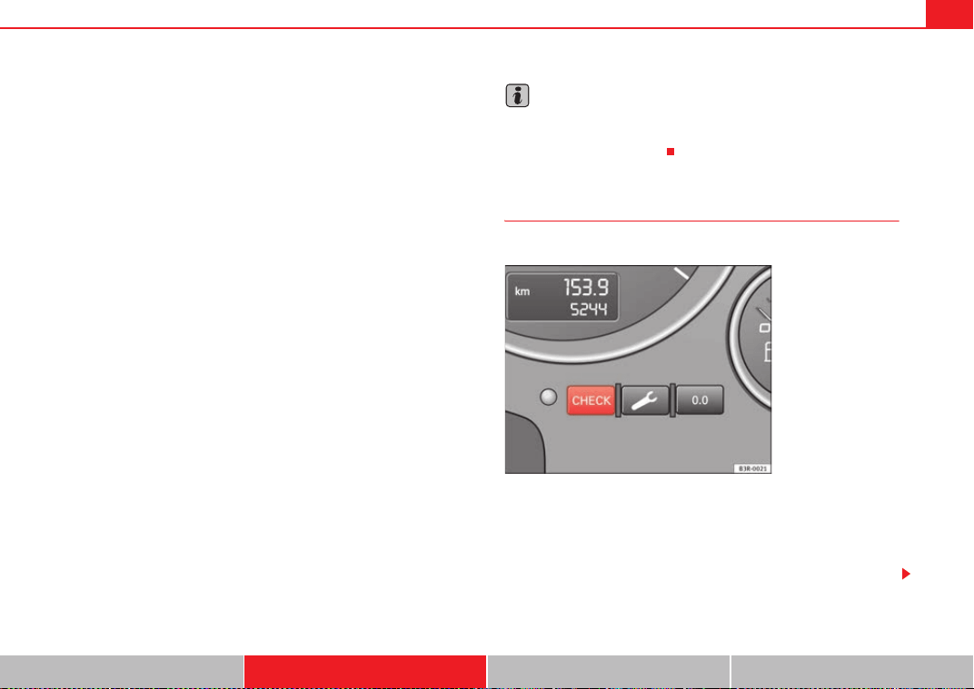
Cockpit 83
Safety First Operating Instructions Practical Tips Technical Specifications
exceeded by about 10 km/h. A warning symbol will also appear in the display
⇒ fig. 56.
The speed warning function has two different warning speeds, which operate
independently and serve slightly different purposes:
Speed limit warning 1
With speed limit warning 1, the maximum speed can be changed while
driving. The speed limit that has been set remains stored until the ignition is
switched off, or until it is changed or cleared.
The warning symbol
for speed limit warning 1 ⇒ page 82, fig. 56 will
appear in the display if you exceed the pre-set speed. It goes out again if the
speed is reduced below the set speed limit.
The symbol also goes out if the speed is increased to more than about 40
km/h above the set speed for at least 10 seconds. However, this does not
cancel the speed limit that was originally set.
Setting speed limit warning 1 ⇒ page 83.
Speed limit warning 2
With speed limit warning 2, the speed limit can only be changed or cleared
when the ignition is switched off. You are recommended to store this speed
limit warning if you always wish to be reminded of a particular speed limit.
This could be when driving in countries with general speed limits, or if a
particular speed should not be exceeded when winter tyres are fitted etc.
The speed limit warning symbol
for speed warning 2 will appear in the
display if you exceed the pre-set speed. Unlike speed limit warning 1, the
warning symbol only goes out once the road speed has dropped below the
set value again.
Setting speed limit warning 2 ⇒ page 84.
Note
Please bear in mind that, even with the speed warning function, it is still
important to keep a eye on the vehicle's speed with the speedometer and to
observe the legal speed limits.
Setting speed limit warning 1
Use the CHECK button to set speed limit warning 1.
Setting the speed limit
– Drive at the desired maximum speed.
– Press the CHECK button and hold it down until the symbol
⇒ page 82, fig. 56 appears.
Fig. 57 Detailed view of
the instrument panel:
CHECK button
ExeoST_EN.book Seite 83 Freitag, 3. September 2010 11:41 11
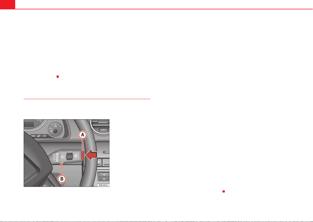
Cockpit84
Clearing the speed limit
– Drive the vehicle at a minimum of 5 km/h.
– Press the CHECK button for at least two seconds.
The speed warning symbol lights up briefly in the display when the button
is released to confirm that the selected speed has been stored. The speed
limit that has been selected remains stored until another speed is selected
with a brief push of the button, or until the memory is cleared with a long
push of the button.
Setting speed limit warning 2
Speed limit warning 2 is set using the switches on the wind-
screen wiper lever.
Setting the speed limit
– Switch the ignition off.
– Briefly press the CHECK button in the instrument panel
⇒ page 83, fig. 57. The odometer and the digital clock will light
up.
– Press the CHECK button for at least two seconds. The display will
show the speed limit which is currently set or, if no speed limit
has been set, the crossed out warning symbol for speed limit 2.
– To change the speed limit, press the top or bottom of the function
selector switch on the windscreen wiper lever ⇒ fig. 58. The
speed limit displayed will then increase or decrease by 10 km/h
at a time.
Clearing the speed limit
– Switch the ignition off.
– Briefly press the CHECK button in the instrument panel
⇒ page 83, fig. 57. The odometer and the digital clock will light
up.
– Press the CHECK button for at least two seconds. The display will
show the speed limit which is currently set.
– Now press and hold the Reset button on the windscreen wiper
lever ⇒ fig. 58 until the crossed out warning symbol for
speed limit 2 appears on the display.
The display lighting for the odometer and digital clock goes off again a few
seconds after the button is released.
Fig. 58 Windscreen wiper
lever: Function selector
switch
A
A
A
B
ExeoST_EN.book Seite 84 Freitag, 3. September 2010 11:41 11
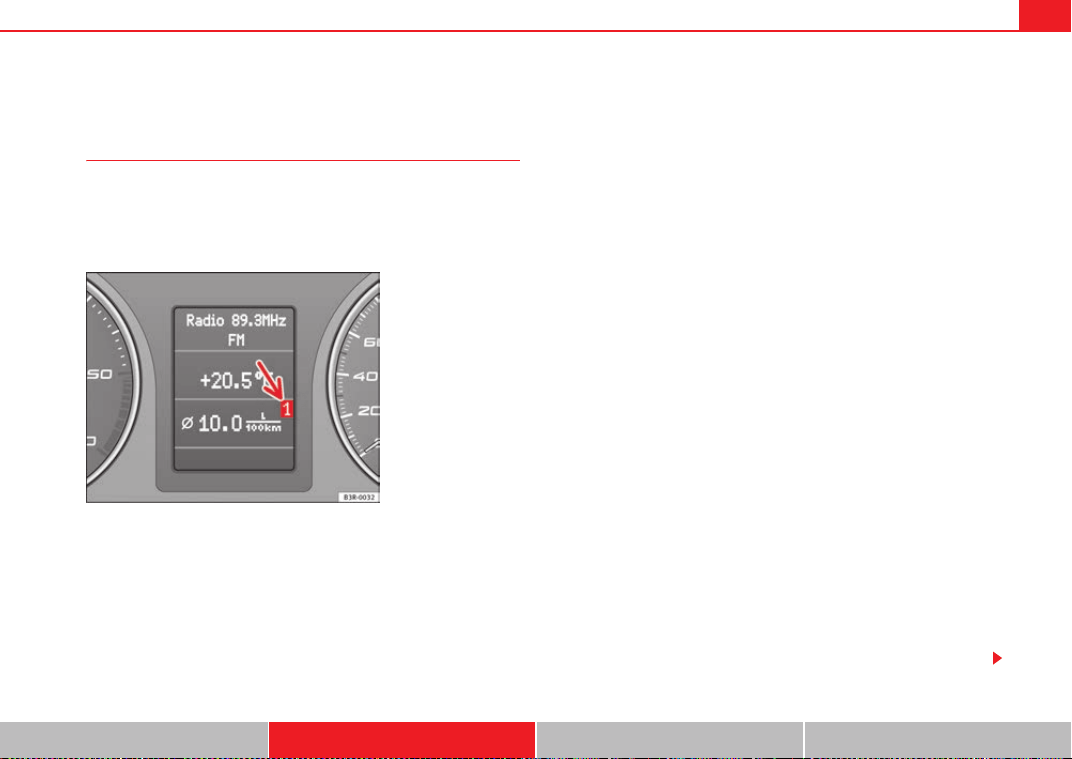
Cockpit 85
Safety First Operating Instructions Practical Tips Technical Specifications
Onboard computer
Introduction
The onboard computer provides you with useful information
during a journey, including average and current fuel
consumption, average speed, distance to empty, driving time
and distance covered.
Press RESET button ⇒ page 86, fig. 60 to switch back and forward
between onboard computer functions 1 and 2.
The numbers in the display ⇒ fig. 59 indicate which of the two memories is
currently in use. A 1 means that the display is showing the information in the
single journey memory (onboard computer 1). A 2 means that the display is
showing the information in the total journey memory (onboard computer 2).
Single-journey memory (onboard computer 1)
The single-journey memory processes the information on a journey from the
time the ignition is switched on until it is switched off. If the journey is
resumed within two hours after the ignition is switched off, the new figures
are automatically included in the calculation. If the journey is interrupted for
more than two hours the stored information is automatically erased when you
resume your journey.
Total-journey memory (onboard computer 2)
Unlike the single-journey memory, the total-journey memory is not erased
automatically. Hence, you can determine the period for which you wish the
onboard computer to supply figures.
Distance to empty
The estimated distance to empty is displayed in km. The distance to empty is
displayed in increments of 10 km.
Average fuel consumption
This mode shows the average fuel consumption since the memory was last
cancelled in litres/100 km.
Instantaneous fuel consumption
The display shows the instantaneous fuel consumption in litres/100 km.
When the vehicle is stationary, the computer will display the last value in the
memory.
Average speed
This mode shows the average speed driven since the memory was last
cancelled (in km/h).
Driving time
This display shows the period of time which has elapsed since the memory
was last cancelled. The longest possible period it can cover is 999 hours and
59 minutes.
Fig. 59 Onboard
computer: memory 1
A
B
ExeoST_EN.book Seite 85 Freitag, 3. September 2010 11:41 11
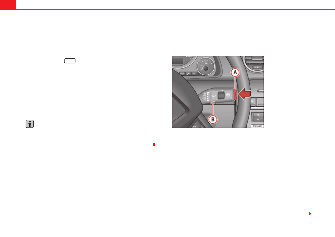
Cockpit86
Driving time warning
After 2 hours of continuous driving, the display automatically switches over
to the driving time display of 2:00. At the same time the driving time display
starts flashing. This is to remind the driver to take a break.
The driving time warning can be switched off by briefly pressing the function
selector switch or the button ⇒ fig. 60.
If you continue driving or take a break for less than 10 minutes, the driving
time warning will switch on once again when the total driving time is 4:00
hours, 6:00 hours, etc. However, if you take a break for more than 10 minutes,
the driving time warning clock will be erased.
Distance covered
This display shows the distance you have covered since the memory was last
cancelled. The longest possible distance which can be recorded is
9999.9 km.
Note
• The displays for fuel consumption (average and instantaneous), distance
to empty and speed are shown in metric units.
• The information in the memory is lost if the battery is disconnected.
Operation
The onboard computer is controlled by means of two switches
on the windscreen wiper lever.
Activating the onboard computer
– Press the reset button repeatedly until the onboard computer
(memory 1 or 2) ⇒ page 85, fig. 59 is displayed.
Selecting the function
– Press the top or bottom of the function selector switch
⇒ fig. 60. This displays the functions of the onboard computer in
sequence.
Resetting to zero
– Press and hold the Reset button for at least two seconds.
The following values can be reset to zero using the Reset button:
Reset
Fig. 60 Windscreen wiper
lever: Onboard computer
controls
A
B
A
A
A
B
ExeoST_EN.book Seite 86 Freitag, 3. September 2010 11:41 11
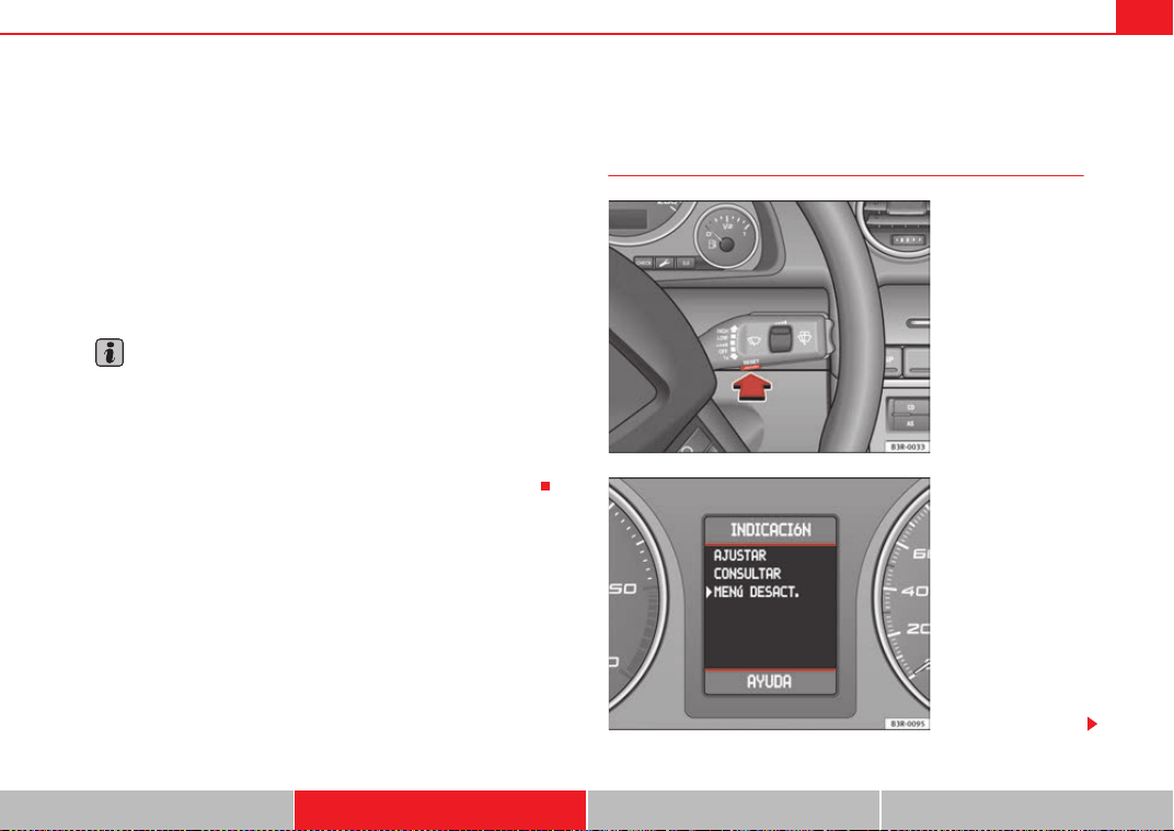
Cockpit 87
Safety First Operating Instructions Practical Tips Technical Specifications
• Journey duration
• Distance covered
• Average fuel consumption
• Average speed
The onboard computer can only be operated when the ignition is switched on.
When the ignition is switched on, the display shows the function that was last
selected.
As well as the figures from the onboard computer (1 or 2), the display can also
show information from the navigation system*. Press the Reset button
briefly to switch back and forward between these displays.
Note
• If you keep the Reset button pressed for longer than two seconds, it will
reset the currently displayed figure to zero (for instance average fuel
consumption).
• Faults detected by the auto-check control will be displayed even if the
display is off.
• The information in the memory is lost if the battery is disconnected.
Menu display
Introduction
A
B
Fig. 61 Windscreen wiper
lever: Menu selection
button
Fig. 62 Display: Main
menu
ExeoST_EN.book Seite 87 Freitag, 3. September 2010 11:41 11
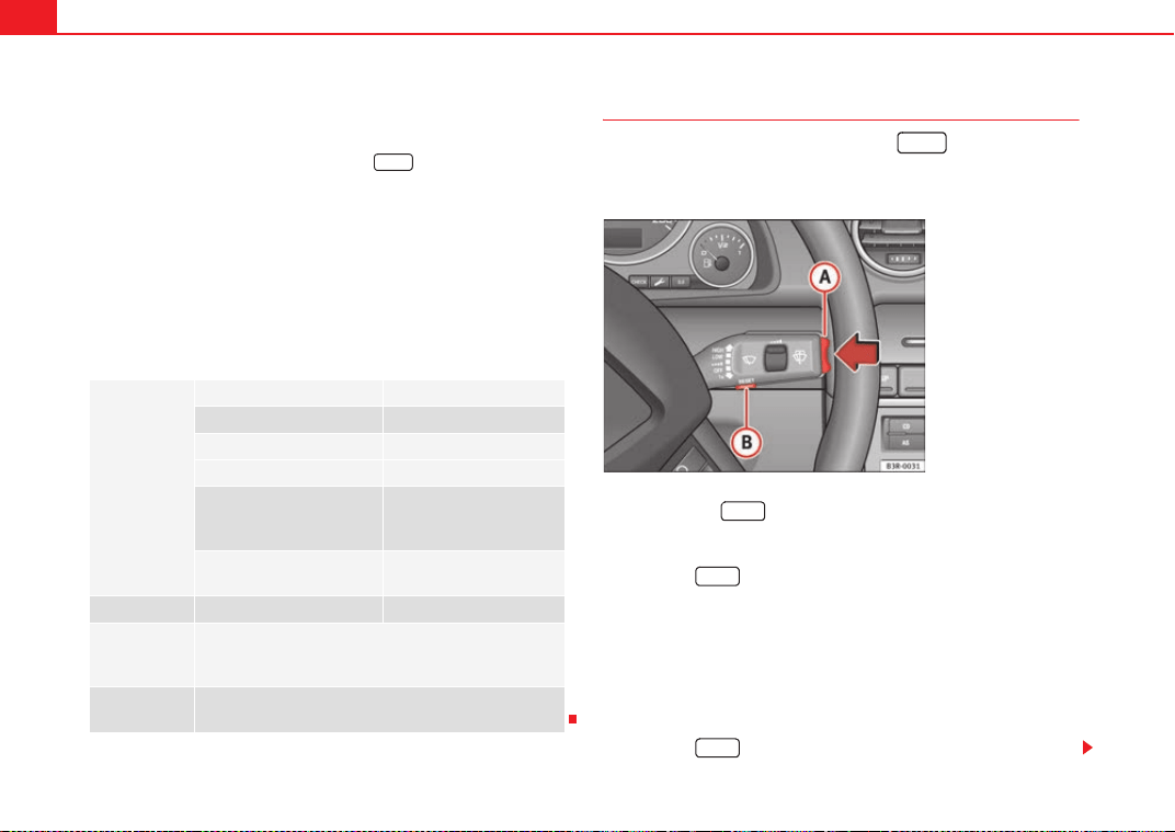
Cockpit88
Some of your vehicle's functions can be adjusted, activated and controlled by
menus. With the aid of the menus you can then also select the information
you wish to see displayed on the DIS display. This is only possible when the
ignition is on. The menu is enabled using the button on the wind-
screen wiper lever ⇒ page 87, fig. 61.
The main menu lists the different display types (or basic commands):
Programming
Check
Menu off
Help
The main menu options have the following submenus:
Controlling the menu
The menu display is called up via the button and the
rocker switch on the windscreen wiper lever. Use these
controls to make checks and adjust the settings.
Functions of the ⇒ fig. 63 and the rocker switch :
Activating the menu
– Press the button until the menu display ⇒ page 87,
fig. 62 appears.
Selecting and setting
– Press the rocker switch to select one of the menus. Press "up" or
"down" on the switch to select the options accordingly.
Entering and confirming
–Press the button.
Programming Clock ⇒ page 88
Computer ⇒ page 88
Speed warning ⇒ page 82
Radio info (on/off)
Units (measuring distance,
fuel consumption, tempera-
ture)
⇒ page 88
Language: you can select
one of 6 languages.
⇒ page 88
Check Service ⇒ page 74
Menu off When the menu is switched off, the display shows the
same information as in vehicles without the menu func-
tion.
Help The help function may be used to understand the meaning
of symbols that can appear on different menus.
Reset
Reset
Fig. 63 Windscreen wiper
lever: Reset button and
rocker switch
Reset
A
B
A
A
Reset
Reset
ExeoST_EN.book Seite 88 Freitag, 3. September 2010 11:41 11
Cockpit 89
Safety First Operating Instructions Practical Tips Technical Specifications
Use the rocker switch to select the menus and adjust various values. The
selected values are highlighted on a red background.
By pressing the button, you can confirm the option you have selected
or the value you have set. Selected functions are marked with a tick.
The following symbols are used:
Tyre pressure monitoring*
Introduction
The tyre pressure monitoring system constantly checks the
pressure of the tyres.
The system warns the driver in the event of a loss of pressure by means of
symbols and messages in the instrument panel display. The system works
with the help of the ABS sensors in the wheels.
Please bear in mind that the tyre inflation pressure is also influenced by the
temperature of the tyre. Tyre pressure increases about 0.1 bar for each 10 °C
in tyre temperature increase. The tyre heats up while the vehicle is being
driven and the tyre pressure will rise accordingly. Therefore, you should only
adjust the tyre pressures when they are cold (i.e. approximately at ambient
temperature).
To ensure that the tyre pressure monitoring system works reliably, you should
check and, if necessary, adjust the tyre pressures at regular intervals and
store the correct pressures (reference values) in the system.
A tyre pressure information label is attached to the inside of the fuel tank flap.
WARNING
• Never adjust tyre pressure when the tyres are hot. This may damage or
even burst the tyres. Risk of accident!
• An insufficiently inflated tyre flexes a lot more at high speeds and
causes significant heating of the tyre. Under these conditions, the tyre
bead may be released or the tyre may burst. Risk of accident!
For the sake of the environment
Under-inflated tyres lead to increased fuel consumption and tyre wear.
Note
• Responsibility for ensuring that the tyres are correctly inflated remains
with the driver; the system can only provide assistance.
• Pressure can only be adjusted when the tyres are at ambient
temperature.
Cursor Function selected Red background (active
function)
d
Tick Selected
c
Box Not selected
`
Triangle pointing upwards Previous page
a
Triangle pointing down-
wards
Next page
Reset
ExeoST_EN.book Seite 89 Freitag, 3. September 2010 11:41 11

Cockpit90
Tyre pressure monitoring display ~
The tyre pressure should be corrected as soon as possible if
it is too low.
If the ~ symbol appears, the tyre pressure on at least one of the
wheels is too low.
– Stop the vehicle.
– Check the tyre(s).
– Correct the tyre pressure ⇒ page 246.
For more detailed information on the tyre pressure monitoring system, please
refer to ⇒ page 245.
ExeoST_EN.book Seite 90 Freitag, 3. September 2010 11:41 11
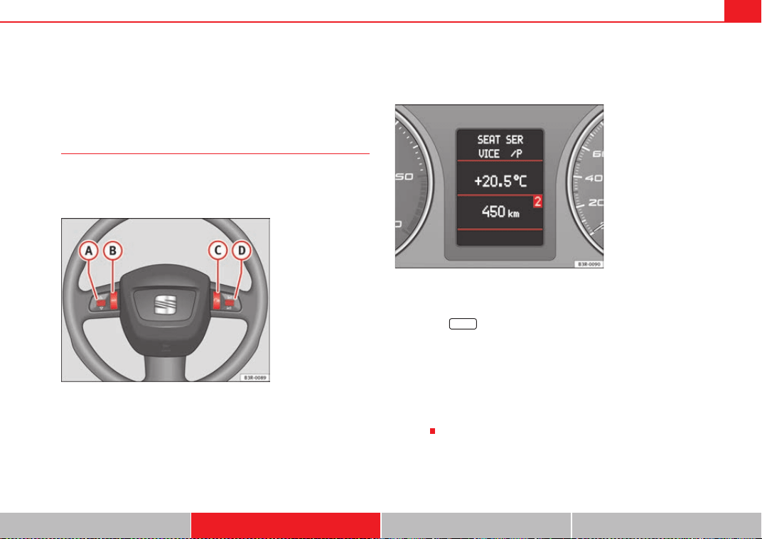
Steering wheel controls 91
Safety First Operating Instructions Practical Tips Technical Specifications
Steering wheel controls
Multifunction steering wheel*
Introduction
You can use the multifunction steering wheel to quickly and
easily operate selected functions of the radio, CD, and tele-
phone*.
The functions are operated by pressing or scrolling the controls to on
the multifunction steering wheel ⇒ fig. 64:
• Press the button repeatedly to switch between modes, which
are then displayed in the driver information system ⇒ fig. 65.
• Scroll and press the left thumbwheel to select a function from one of
the menus.
• The speech control system* for the on-board phone system is enabled by
pressing the talk button . Pressing the talk button again disables speed
control*.
• Scroll the right thumbwheel up/down to increase/decrease the
volume.
Fig. 64 Controls on the
multifunction steering
wheel
Fig. 65 Driver informa-
tion system
A
A
A
D
MODE
A
B
A
A
A
C
A
D
ExeoST_EN.book Seite 91 Freitag, 3. September 2010 11:41 11
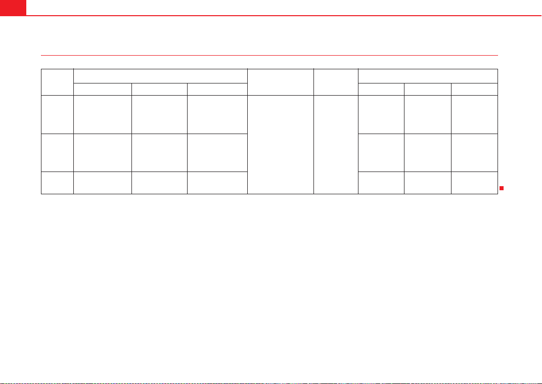
Steering wheel controls92
Steering wheel audio version controls
(Mode) (PTT)
+-Press +-Press
Radio
mode
Station search.
Increase frequency
Station search.
Decrease fre-
quency
1st press: starts
the search.
2nd press: cancels
the search
Long press:
block the steering
wheel controls
Short press:
activates the steer-
ing wheel controls (if
they are blocked /
without specific func-
tion (if they are not
blocked)
No function
specified
Volume up Volume down MUTE
CD/
iPod-USB
Mode
CD mode: next
track.
iPod/USB Mode:
next track
CD mode: previ-
ous track.
iPod/USB Mode:
previous track
CD mode: fast for-
ward.
iPod/USB Mode:
fast forward
Volume up Volume down MUTE
MP3
mode
Next track Previous track Fast forward Volume up Volume down MUTE
A
A
A
B
A
C
A
D
ExeoST_EN.book Seite 92 Freitag, 3. September 2010 11:41 11
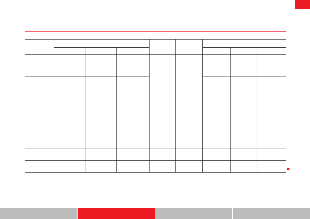
Steering wheel controls 93
Safety First Operating Instructions Practical Tips Technical Specifications
Steering wheel Audio + Telephone version controls
(Mode) (PTT)
+-Press +-Press
Radio mode
Station search.
Increase fre-
quency
Station search.
Decrease fre-
quency
1st press: starts
the search.
2nd press: cancels
the search
Change to
phone
Enable voice
recognition
Volume up Volume down MUTE
CD/
iPod-USB Mode
CD mode: next
track.
iPod/USB Mode:
next track
CD mode: previ-
ous track.
iPod/USB Mode:
previous track
CD mode: fast for-
ward.
iPod/USB Mode:
fast forward
Volume up Volume down MUTE
MP3 mode Next track Previous track Fast forward Volume up Volume down MUTE
Phone mode
Next name in
phone book
Previous name in
phone book
Accept
Change to
radio / CD /
iPod-USB /
MP3
Volume up Volume down
No function
specified
Incoming call
mode
No function spec-
ified
No function
specified
One press: accept
call.
Held down: reject
call
No function
specified
No function
specified
Volume up Volume down
No function
specified
Active call
mode
No function spec-
ified
No function
specified
End call
No function
specified
No function
specified
Volume up Volume down
No function
specified
Voice activa-
tion mode
No function spec-
ified
No function
specified
No function speci-
fied
No function
specified
Cancel Volume up Volume down
No function
specified
A
A
A
B
A
C
A
D
ExeoST_EN.book Seite 93 Freitag, 3. September 2010 11:41 11

Steering wheel controls94
Steering wheel controls, Navigation System* version
(Mode) (PTT)
+-Press +-Press
Radio mode
Station search.
Increase fre-
quency
Station search.
Decrease fre-
quency
1st press: starts
the search.
2nd press: cancels
the search
No function
specified
No function
specified
Volume up Volume down
Repetition of
the last naviga-
tion order (only
if active)
CD/
iPod-USB Mode
CD mode: next
track.
iPod/USB Mode:
next track
CD mode: previ-
ous track.
iPod/USB Mode:
previous track
CD mode: fast for-
ward.
iPod/USB Mode:
fast forward
Volume up Volume down
Repetition of
the last naviga-
tion order (only
if active)
MP3 mode Next track Previous track Fast forward Volume up Volume down
Repetition of
the last naviga-
tion order (only
if active)
A
A
A
B
A
C
A
D
ExeoST_EN.book Seite 94 Freitag, 3. September 2010 11:41 11
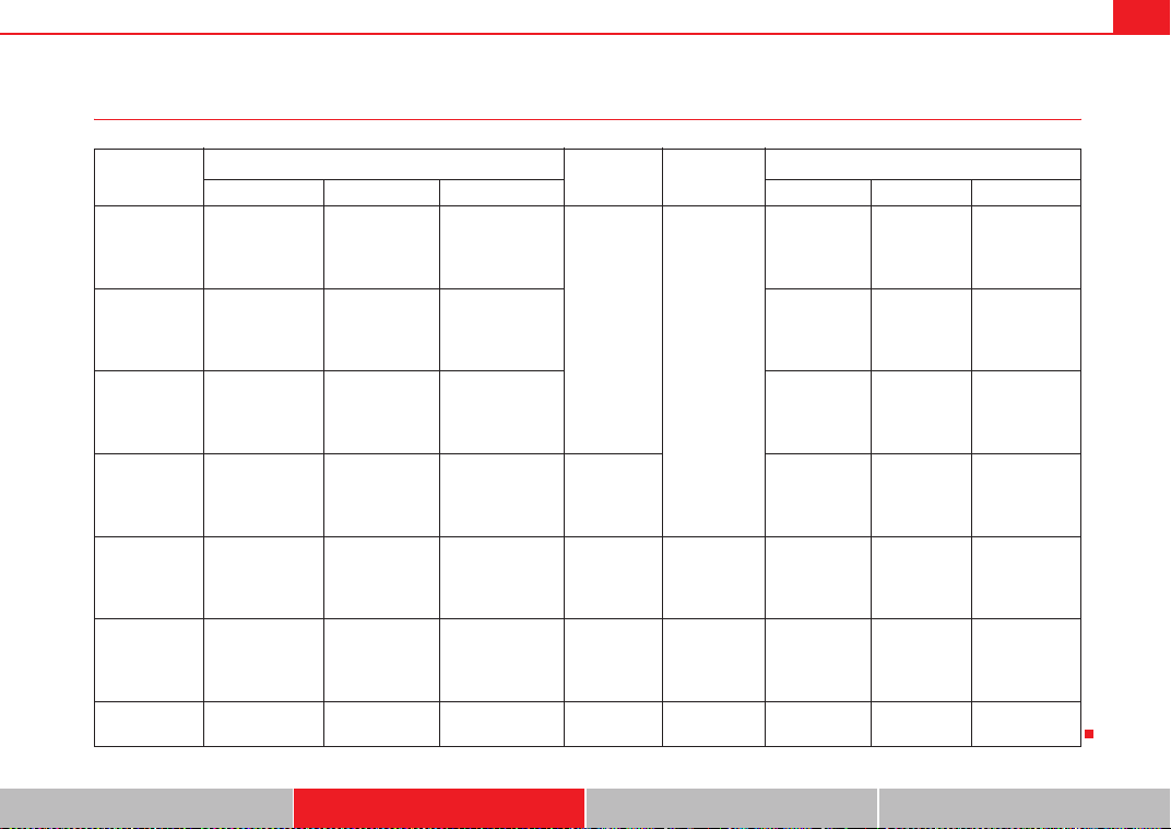
Steering wheel controls 95
Safety First Operating Instructions Practical Tips Technical Specifications
Steering wheel controls, Navigation System + Telephone* version
(Mode) (PTT)
+-Press +-Press
Radio mode
Station search.
Increase fre-
quency
Station search.
Decrease fre-
quency
1st press: starts
the search.
2nd press: cancels
the search
Change to
phone
Enable voice
recognition
Volume up Volume down
Repetition of
the last naviga-
tion order (only
if active)
CD/
iPod-USB Mode
CD mode: next
track.
iPod/USB Mode:
next track
CD mode: previ-
ous track.
iPod/USB Mode:
previous track
CD mode: fast for-
ward.
iPod/USB Mode:
fast forward
Volume up Volume down
Repetition of
the last naviga-
tion order (only
if active)
MP3 mode Next track Previous track Fast forward Volume up Volume down
Repetition of
the last naviga-
tion order (only
if active)
Phone mode
Next name in
phone book
Previous name in
phone book
Accept
Change to
radio / CD /
iPod-USB /
MP3
Volume up Volume down
Repetition of
the last naviga-
tion order (only
if active)
Incoming call
mode
No function spec-
ified
No function
specified
One press: accept
call.
Held down: reject
call
No function
specified
No function
specified
Volume up Volume down
Repetition of
the last naviga-
tion order (only
if active)
Active call
mode
No function spec-
ified
No function
specified
End call
No function
specified
No function
specified
Volume up Volume down
Repetition of
the last naviga-
tion order (only
if active)
Voice activa-
tion mode
No function spec-
ified
No function
specified
No function speci-
fied
No function
specified
Cancel Volume up Volume down
No function
specified
A
A
A
B
A
C
A
D
ExeoST_EN.book Seite 95 Freitag, 3. September 2010 11:41 11
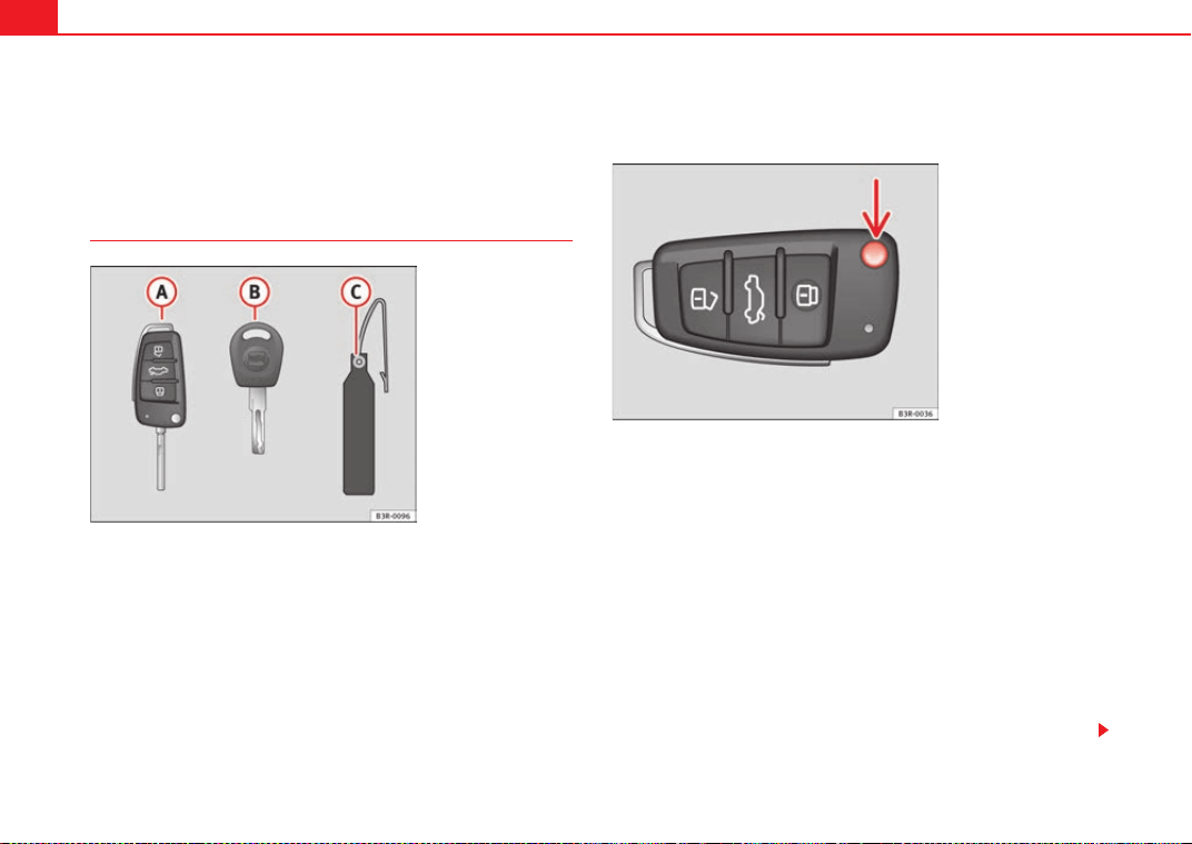
Unlocking and locking96
Unlocking and locking
Remote control keys
Set of keys
The set of keys belonging to your vehicle consists of the following items:
one remote control key.
one key without remote control.
a plastic key tab*.
Remote control key
The remote control key will lock and unlock the vehicle and start the engine.
Press the release button ⇒ fig. 67 -arrow- to unfold the key out of the handle
and to fold it back in.
Replacing a key
If you lose a key, please contact the Technical Service. Have the remote
control coding for that key disabled. You should therefore bring the plastic
key tab* and all available keys with you. It is also important to notify your
insurance company if a key or the plastic key tab has been lost.
Fig. 66 Set of keys
supplied with the vehicle
Fig. 67 Remote control
key: Release button
A
A
A
B
A
C
ExeoST_EN.book Seite 96 Freitag, 3. September 2010 11:41 11
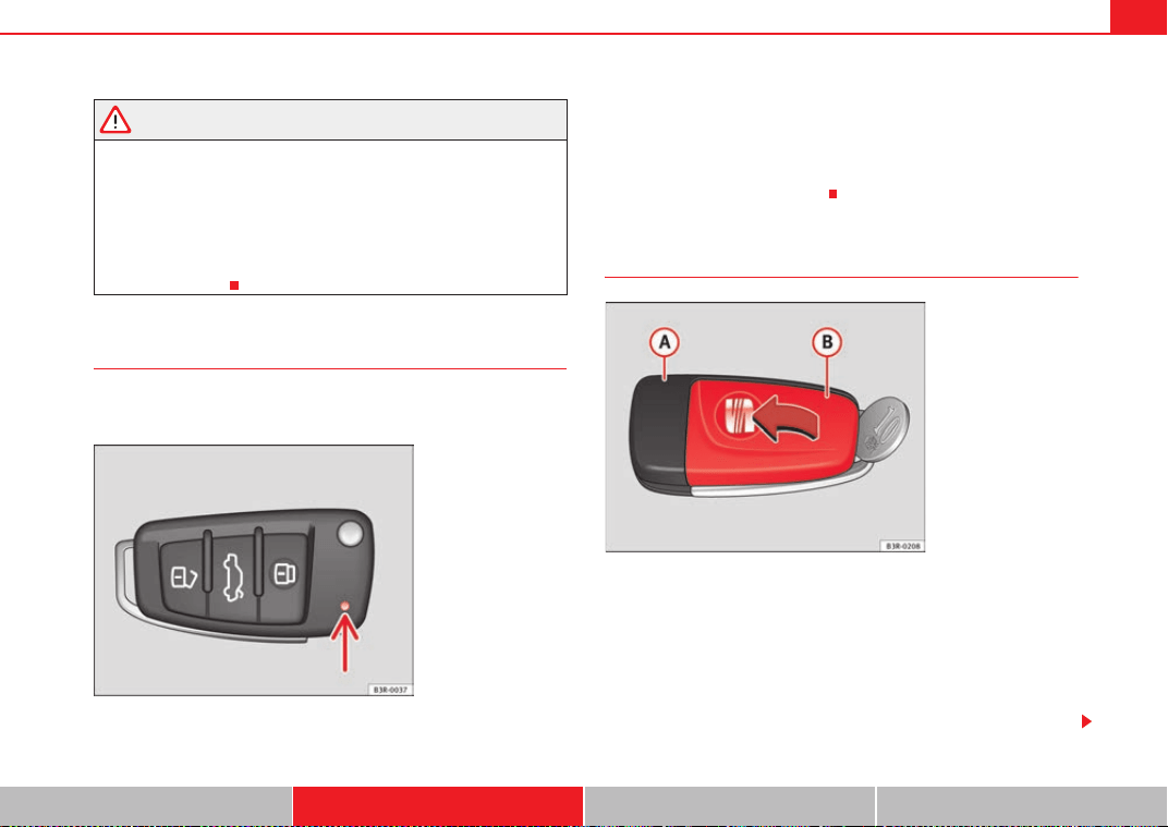
Unlocking and locking 97
Safety First Operating Instructions Practical Tips Technical Specifications
WARNING
• Always take the key with you when leaving the vehicle, even if you only
intend to be gone for a short time. This is particularly important if there are
children in the vehicle, as they might otherwise be able to start the engine
or use power-operated equipment (e.g. the electric windows), which could
cause injuries.
• Wait for the vehicle to come to a standstill before removing the ignition
key from the lock! Otherwise, the steering lock could engage suddenly,
causing an accident.
Indicator light on the remote control key
The condition of the battery in the remote control key is moni-
tored by the indicator light.
Condition of the key battery
The indicator light ⇒ fig. 68 (arrow) flashes when one of the buttons is
pressed. If the indicator light does not light up or flash, this means that the
battery is exhausted and must be replaced.
Replacing the batteries ⇒ page 97.
Replacing the key battery
We recommend you have the batteries changed in a qualified work-
shop. If you decide to change the used battery yourself, follow the
steps below:
– Carefully prise apart the key ⇒ fig. 69 and the cover
using a coin.
– Remove the cover in the direction of the arrow.
Fig. 68 LED on the remote
control key
Fig. 69 Master key:
Opening the cover
A
A
A
B
ExeoST_EN.book Seite 97 Freitag, 3. September 2010 11:41 11
Unlocking and locking98
– Remove the used battery from the cover.
– Insert the new battery. Make sure that the “+” symbol on the
battery is facing downwards. The correct polarity is indicated on
the cover.
– After inserting the battery, align the cover and key and press the
two parts together.
For the sake of the environment
Used batteries must be disposed of at an appropriate waste facility or
through an authorised service, given that their components can affect the
environment.
Note
• The system must be re-synchronised after each battery replacement to be
able to lock and unlock the vehicle using the remote control ⇒ page 107.
• The new battery must be of the same type as the original.
Electronic immobiliser
The electronic immobiliser is designed to prevent unauthor-
ised persons from starting up the vehicle.
There is an electronic chip inside the key which automatically deactivates the
immobiliser when the key is inserted into the ignition lock. The electronic
immobiliser is enabled automatically when the ignition key is removed from
the ignition lock after coming to a stop.
If an uncoded key is used, the message SAFE will appear in the trip recorder
display.
Note
• The engine can only be started using an original SEAT key with the correct
code.
• It may not be possible to start the engine with the key if there is another
ignition key from a different make of vehicle on the same key tab.
Central locking
Description
The central locking system enables you to lock and unlock all
the doors, the tailgate and the tank flap together.
The central locking system on your vehicle locks and unlocks all the doors
and the tank flap simultaneously. The tailgate is unlocked when the vehicle
is opened. However, the handle must be used to open it. The vehicle can be
locked and unlocked using the remote control ⇒ page 105 or by turning the
key in the lock in the driver door.
The windows can also be centrally opened or closed using the central locking
system ⇒ page 111. The sunroof* can be closed but not opened using the
central locking system.
The central locking system is combined with an anti-theft security system. If
the vehicle is locked with the key from the outside, the interior opening levers
stop working, which prevents unauthorised persons from entering the
vehicle.
Should the central locking system fail to work, you can still normally enable
all the locks individually.
ExeoST_EN.book Seite 98 Freitag, 3. September 2010 11:41 11
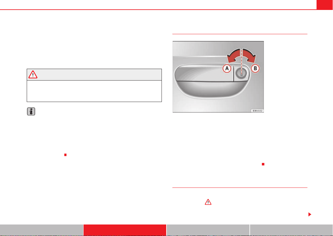
Unlocking and locking 99
Safety First Operating Instructions Practical Tips Technical Specifications
Automatic locking function (Auto Lock)*
The Auto Lock* function automatically locks all doors and the tailgate when
the vehicle exceeds a speed of about 15 km/h.
The vehicle is unlocked again automatically when the ignition key is
removed. Alternatively, the driver can also unlock the vehicle using the
central locking switch
or by opening one of the doors.
WARNING
Do not leave anyone (especially children) in the vehicle if it is locked from
the outside and the anti-theft security system is enabled, as the doors and
windows cannot then be opened from the inside. Locked doors could delay
assistance in an emergency, potentially putting lives at risk.
Note
• Should the central locking system fail to work, you can still lock and
unlock the driver door and the tailgate using the key. Locking the doors
manually if central locking fails to work ⇒ page 102.
• The anti-theft mechanism and the anti-theft alarm* cannot be enabled if
the central locking is not working.
• Never leave any valuable items in the vehicle unattended. Even a locked
vehicle is not a safe.
Unlocking the vehicle with the key
– To unlock the vehicle, turn the key in the driver door to position
⇒ fig. 70.
– Pull the handle to open the door.
• This will unlock all the doors, the tailgate and the tank flap simultane-
ously.
• The anti-theft security system will be disabled.
Locking the vehicle with the key
– To lock the vehicle, turn the key in the driver door to position
⇒ fig. 70 ⇒ .
• This will lock all the doors and the tailgate.
Fig. 70 Turning the key to
enable the open and close
functions
A
A
A
B
ExeoST_EN.book Seite 99 Freitag, 3. September 2010 11:41 11
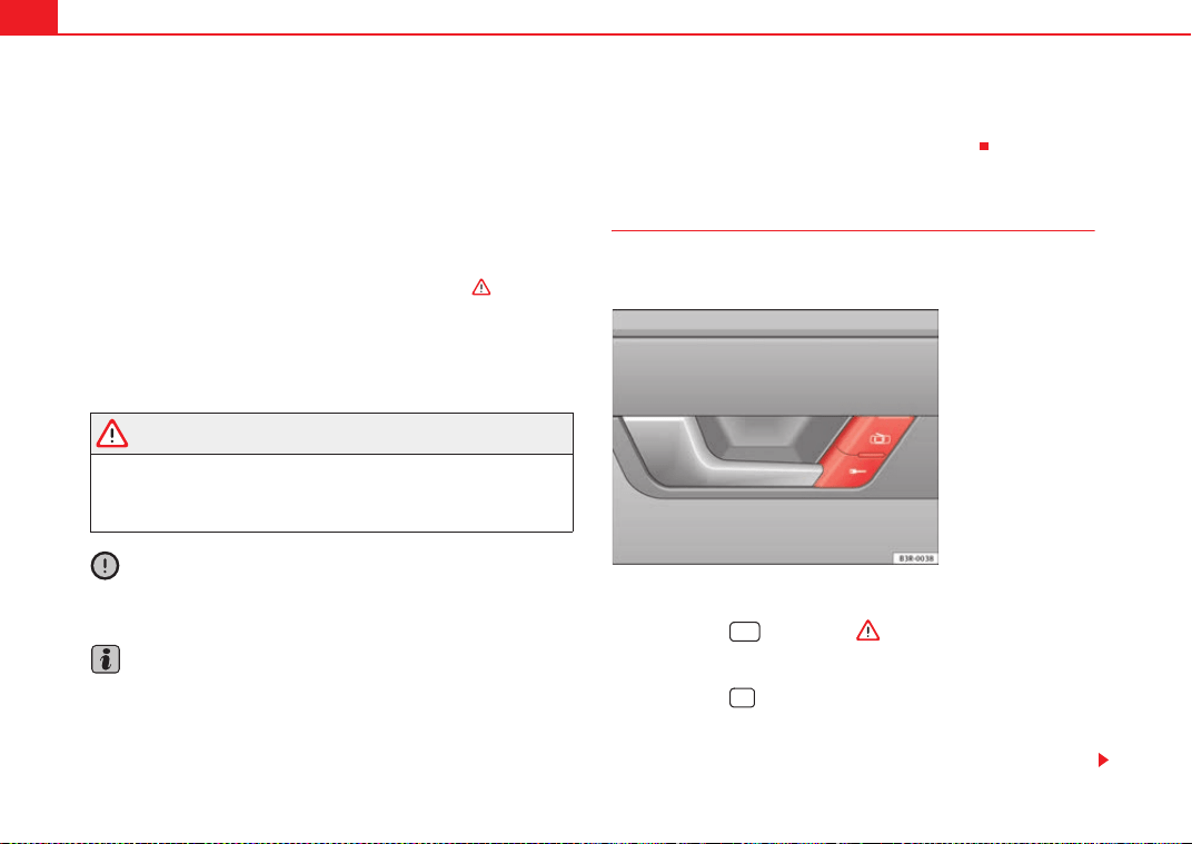
Unlocking and locking100
• The interior lights are switched off, provided the light switch is in the cour-
tesy light position.
• The windows and the sunroof* will close as the key is held in the locking
position.
• The anti-theft security system will be enabled immediately.
Locking the vehicle without activating the anti-theft security system
With the anti-theft security system enabled, it is more difficult to break into
the vehicle. If the anti-theft security system has been enabled, the inside
door handles and the central locking switch will not work ⇒ .
If you are leaving passengers in the vehicle while it is parked, it is possible to
lock the vehicle without activating the anti-theft security system.
To do so, turn the key in the driver door twice in quick succession to position
⇒ page 99, fig. 70.
WARNING
Do not leave anyone (especially children) in the vehicle if it is locked from
the outside and the anti-theft security system is enabled, as the doors and
windows cannot then be opened from the inside. Locked doors could delay
assistance in an emergency, potentially putting lives at risk.
Caution
If the driver door is locked using the key while open, the vehicle will be auto-
matically immobilised and the alarm triggered.
Note
• Please note that when the vehicle is locked without activating the anti-
theft mechanism, the anti-theft alarm* remains operative. You should there-
fore switch off the interior monitoring* before locking the vehicle, as other-
wise the alarm* could be triggered unintentionally.
• The driver door cannot be locked using the central locking system when it
is still open. The door must be locked separately after it has been closed. This
helps to prevent you from being locked out of the vehicle.
Central locking switch
The central locking system can be enabled from inside the
vehicle using the central locking switch on the driver door.
Locking the vehicle
–Press button ⇒ fig. 71 ⇒ .
Unlocking the vehicle
–Press button .
Please note the following when using the central locking switch to lock your
vehicle:
A
B
Fig. 71 Detail of the
driver door: Central
locking switch
ExeoST_EN.book Seite 100 Freitag, 3. September 2010 11:41 11
Unlocking and locking 101
Safety First Operating Instructions Practical Tips Technical Specifications
• The doors and the tailgate cannot be opened from the outside (for secu-
rity reasons, e.g. when stopped at traffic lights).
• You can open the doors individually from the inside by pulling the inside
door handle.
• When the driver door is open, it cannot be locked by pressing the central
locking switch and then closing the door. This helps to prevent you from
being locked out of the vehicle. The door has to be locked separately after it
has been closed.
• In the event of an accident in which the airbags inflate, doors locked from
the inside will be automatically unlocked to facilitate access and assistance.
WARNING
The central locking switch is still operative when the ignition is switched
off. This switch can be used to automatically lock all the doors and the tail-
gate. However, since this makes it difficult to enter the vehicle from the
outside, you should never leave children unattended in the vehicle. Locked
doors could delay assistance in an emergency, potentially putting lives at
risk.
Note
The central locking switch inside the vehicle will not be operative if the anti-
theft mechanism has been enabled.
Security central locking*
The security central locking feature allows you to only unlock
the driver door and the tank flap. All other doors and the tail-
gate remain locked.
Unlocking the driver door and tank flap
–Turn the key once to the unlock position, or press the unlock
button on the remote control once.
Unlocking all the doors, the tailgate and the tank flap
simultaneously.
–Turn the key twice within five seconds, or press the unlock button
on the remote control twice within five seconds.
The security system and the anti-theft alarm* are immediately disabled if you
unlock only the driver door, without unlocking the other doors⇒ page 107.
ExeoST_EN.book Seite 101 Freitag, 3. September 2010 11:41 11
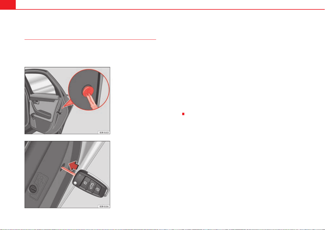
Unlocking and locking102
Locking the doors manually if the central locking fails to
work
Should the central locking system fail to work at any time (for
instance if there is no electrical power supply), each door will
have to be locked separately.
A manual locking device is provided on the front passenger door
and the rear doors (only visible when the door is open).
– Open the door.
–Use the key ⇒ fig. 72 to turn the cap slightly and then fold it
downwards.
– Insert the key into the slot inside ⇒ fig. 73 and turn it as far as
the stop, i.e. about 90 degrees to the right (doors on right side)
or to the left (door on the left side).
Once the door has been closed it can no longer be opened from the outside.
The door can be opened from the inside by pulling the door handle. If the
childproof lock is engaged on one of the rear doors, the door can be opened
by pulling the inside door handle once and then opening the door from the
outside.
Fig. 72 Manual locking
device
Fig. 73 Activating manual
locking
ExeoST_EN.book Seite 102 Freitag, 3. September 2010 11:41 11
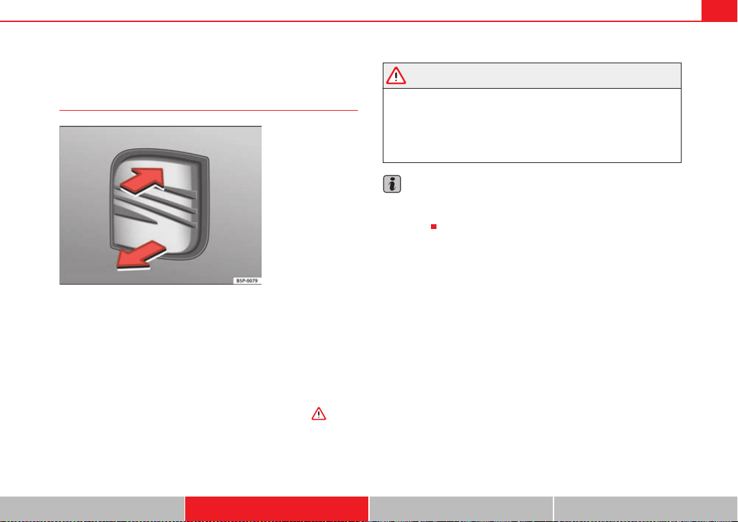
Unlocking and locking 103
Safety First Operating Instructions Practical Tips Technical Specifications
Tailgate
Tailgate: opening and closing
Opening the tailgate
– Pull on the release lever⇒ fig. 74 and lift the tailgate at the same
time.
– Then lift up the tailgate. If your vehicle is equipped accordingly,
the tailgate will open automatically*.
Closing the tailgate
– Pull down the tailgate and let it drop into the latch ⇒ .
Use the recessed handle in the interior trim to make it easier to pull down the
tailgate.
WARNING
• After closing the tailgate, always check that the catch has engaged
properly. If not, the tailgate could open while driving, even if it has been
locked. Risk of accident!
• The tailgate must always be completely closed when the vehicle is
moving, otherwise toxic exhaust fumes may be drawn into the vehicle.
Danger of poisoning!
Note
• The door/tailgate warning symbol lights up on the instrument panel
display if the tailgate is not properly closed when the ignition is switched on
⇒ page 74.
Fig. 74 Luggage
compartment: opening
from the outside
ExeoST_EN.book Seite 103 Freitag, 3. September 2010 11:41 11
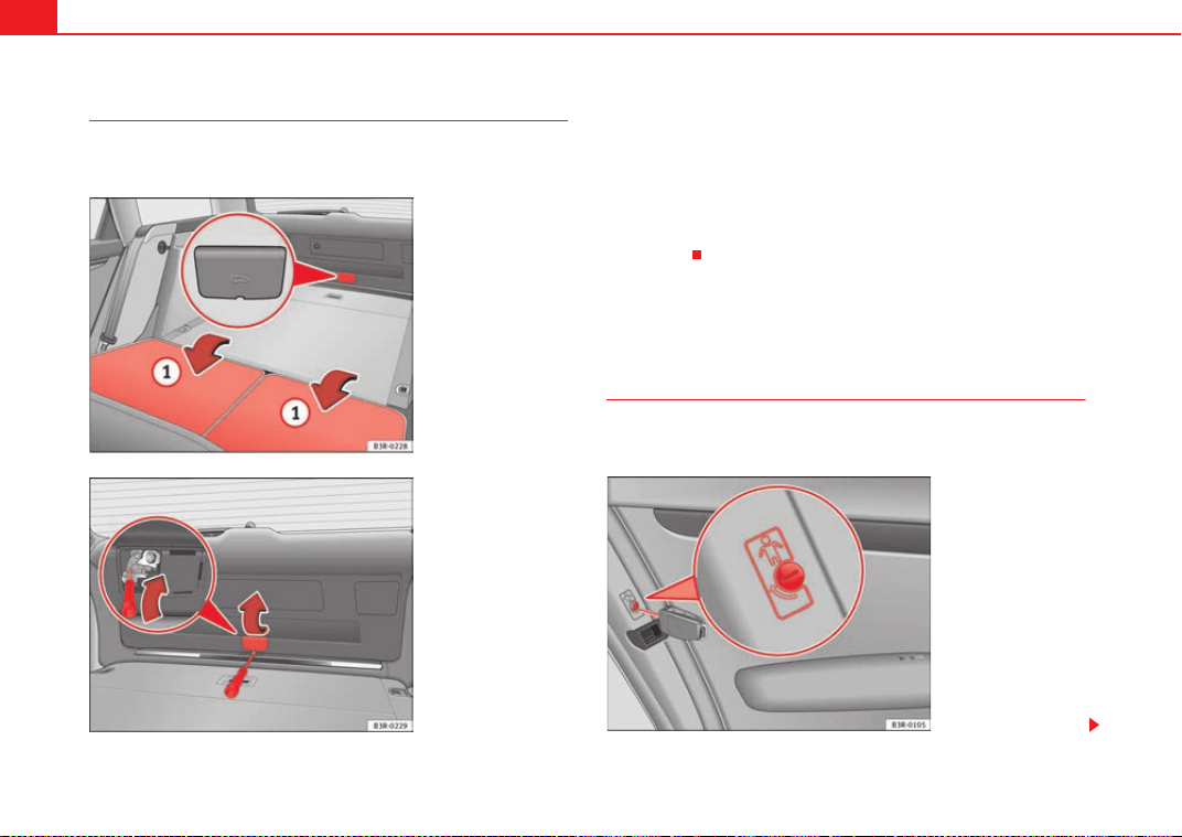
Unlocking and locking104
Unlocking the tailgate manually
The tailgate can be released manually if it will not open in the
normal way.
– Fold down both rear backrests ⇒ fig. 75.
– Lean into the luggage compartment.
– Lift the cover ⇒ fig. 76 -arrow-.
– Insert the screwdriver into the opening ⇒ fig. 76 -arrow- and
push it in the direction of the arrow in order to release the
tailgate.
Childproof lock
Childproof locks on rear doors
The childproof lock prevents the rear doors from being
opened from the inside.
Fig. 75 Detail of the rear
seats and luggage
compartment: access to
the emergency release
mechanism
Fig. 76 Detail of the tail-
gate: emergency
unlocking mechanism
A
1
Fig. 77 Childproof lock
on the rear doors
ExeoST_EN.book Seite 104 Freitag, 3. September 2010 11:41 11
Unlocking and locking 105
Safety First Operating Instructions Practical Tips Technical Specifications
The rear doors are equipped with childproof locks. These can be
operated using the ignition key. The childproof locks are only visible
with the doors open.
Activating the childproof lock
– Turn the key in the direction of the arrow ⇒ page 104, fig. 77.
Deactivating the childproof lock
– Turn the key in the opposite direction of the arrow.
When the childproof lock is enabled, the inside door handle will not work and
the door can only be opened from the outside.
Remote control key
Description
The remote control key will lock and unlock the vehicle
without having to insert the key in the lock.
The following functions are available:
• Locking and unlocking the vehicle
• Unlocking the tailgate
All the turn signals will flash as confirmation when the vehicle is locked or
unlocked. Furthermore, the interior lights will automatically light up when the
vehicle is unlocked and go out when the vehicle is locked, provided that the
switches are in the courtesy light position.
The remote control transmitter and the battery are integrated into the handle
of the key. The receiver is in the interior of the vehicle. The maximum range
depends on different circumstances. The range is reduced when the battery
starts to lose power.
The remote control incorporates a foldaway key that can be used to manually
lock or unlock the vehicle, as well as to start the engine.
If the receiver has been repaired or replaced, or if a replacement key is used,
the system will need re-programming by a qualified workshop. Only then will
you be able use the remote control again.
The remote control meets all relevant authorisation requirements and has
been approved by the Federal Approvals Office for Telecommunications of the
Federal Republic of Germany. All components are marked in accordance with
the current legal requirements. This certification forms the basis for official
approval for use in other countries.
Note
• The remote control is automatically disabled when the ignition is
switched on.
• The function of the remote control may be impaired by interference from
other nearby radio signals (e.g. from a mobile phone or TV transmitter) if
these are in the same frequency range.
ExeoST_EN.book Seite 105 Freitag, 3. September 2010 11:41 11
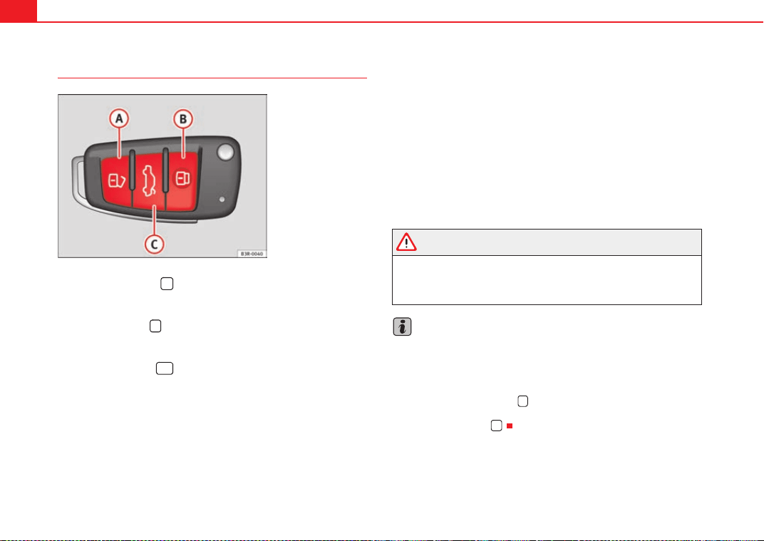
Unlocking and locking106
Locking and unlocking the vehicle
Unlocking the vehicle
–Press button ⇒ fig. 78 for about 1 second.
Locking the vehicle
– Press button for about 1 second.
Opening the tailgate
– Press button and hold for at least one second.
The turn signals will flash twice as confirmation when you unlock the vehicle.
The vehicle will be locked again automatically if you do not open one of the
doors or the tailgate within 60 seconds after unlocking the vehicle with
button . This function prevents the vehicle from remaining unlocked if the
unlocking button is pressed by mistake.
In vehicles with the security central locking* feature, you can unlock just the
driver door and the tank flap by pressing button once or the whole vehicle
by pressing the button twice.
The turn signals flash once when the vehicle is locked to confirm that the
doors and tailgate are properly locked.
Moreover, apart from unlocking the vehicle, the seat* and mirror* memory
programmed in the key is activated. The driver seat and exterior mirrors will
be automatically adjusted to the positions stored in the memory.
The interior lights will automatically light up when the vehicle is unlocked and
go out when the vehicle is locked, provided that the switch is in the courtesy
light position.
WARNING
Do not leave anyone (especially children) in the vehicle if it is locked from
the outside and the anti-theft security system is enabled, as the doors and
windows cannot then be opened from the inside. Locked doors could delay
assistance in an emergency, potentially putting lives at risk.
Note
• The remote control should only be used when the doors and the tailgate
are closed.
• The remote control should not be used when the vehicle is out of sight.
• The anti-theft alarm* can be accidentally triggered and the vehicle locked
if you press the locking button on the remote control inside the vehicle
before inserting the key in the ignition. If this should happen by mistake,
press the unlock button .
Fig. 78 Remote control
key: Control buttons
A
A
A
B
A
C
A
A
A
A
ExeoST_EN.book Seite 106 Freitag, 3. September 2010 11:41 11
Unlocking and locking 107
Safety First Operating Instructions Practical Tips Technical Specifications
Re-synchronising
Should the remote control fail to lock or unlock the vehicle,
the system must be re-synchronised.
– If the vehicle is locked, use the key to unlock the driver door.
– Press the unlock button on the remote control.
– Insert the key into the ignition and switch on the ignition.
– Switch off the ignition and remove the key.
– Press the unlock or the lock button .
Anti-theft alarm system*
Description
The system triggers an alarm if anyone attempts to break into
the vehicle.
The anti-theft alarm helps to prevent the vehicle being broken into or stolen.
If the system senses interference with the vehicle, it triggers an audible and
visible alarm.
How is the system enabled?
The anti-theft alarm system is enabled automatically when the vehicle is
locked with the remote control or by turning the key in the driver door (if the
door is closed). The anti-theft alarm is enabled about 30 seconds after the
vehicle is locked.
How is the system disabled?
The anti-theft alarm is only disabled when the vehicle is unlocked using the
remote control. The vehicle will lock again automatically if none of the doors
is opened within 60 seconds after pressing the remote control button.
If the vehicle is unlocked by turning the key in the driver door, all the other
doors, the tailgate and the tank flap will remain locked.
If the vehicle has been unlocked with the key in the driver door, the key must
be inserted in the ignition lock and the ignition switched on within 15
seconds of opening the door in order to disable the alarm. The alarm will be
triggered if the ignition is not switched on within 15 seconds.
When does the system trigger the alarm?
The following parts of the vehicle are monitored when the vehicle is locked:
• Engine compartment (bonnet)
• Luggage compartment
• Doors
• Tilt angle (tow-away protection)
• Ignition
• Radio (only with a factory-fitted SEAT radio)
• Interior ⇒ page 108
If any of these areas are entered, the alarm will be triggered.
How is the alarm disabled?
The alarm can be switched off by unlocking the vehicle using the remote
control, or by switching on the ignition with the key, thus “disabling” the
alarm system. The alarm will also switch off when it comes to the end of its
cycle.
Turn signals
The turn signals flash briefly when the vehicle is locked to confirm that the
doors, the engine bonnet and the tailgate are properly closed and locked.
ExeoST_EN.book Seite 107 Freitag, 3. September 2010 11:41 11
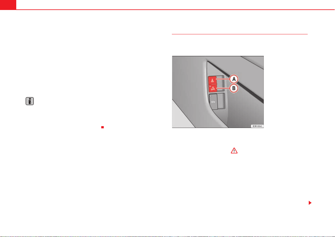
Unlocking and locking108
If the turn signals do not flash, check the doors, the bonnet and the tailgate
to make sure they are properly closed. The turn signals will also flash briefly
if one of the doors or the tailgate or engine bonnet is closed after the alarm
system has been enabled.
LED
When the vehicle is locked, the LED on the top of the driver door trim will flash
rapidly for about 30 seconds and then continue flashing slowly. This is to
indicate that the anti-theft alarm system (including the interior monitoring
and tow-away protection) is operative. If the LED lights up continuously for
about 30 seconds when the vehicle is locked instead of flashing, this means
the alarm system is not working properly.
Note
• To make sure that the alarm is fully operative when leaving the vehicle,
briefly check that all the doors and windows and the sunroof* are closed.
• The alarm is triggered immediately if one of the battery cables is discon-
nected while the alarm system is enabled.
Interior monitoring*
The interior monitoring triggers an alarm if it detects move-
ment inside the vehicle.
You should disable the interior monitoring if there is a possibility
that the alarm could be triggered, e.g. by a pet or by an object
moving inside the vehicle ⇒ . The tow-away protection feature,
which is integrated into the alarm system, should be disabled if the
vehicle is being towed or transported (e.g. by rail or ship).
Deactivating the interior monitoring
– Open the door and pull out the switch (with the symbol
) to
one side of the storage compartment, in the driver door
⇒ fig. 79.
– Then lock the vehicle.
Fig. 79 Interior moni-
toring switch
A
A
ExeoST_EN.book Seite 108 Freitag, 3. September 2010 11:41 11
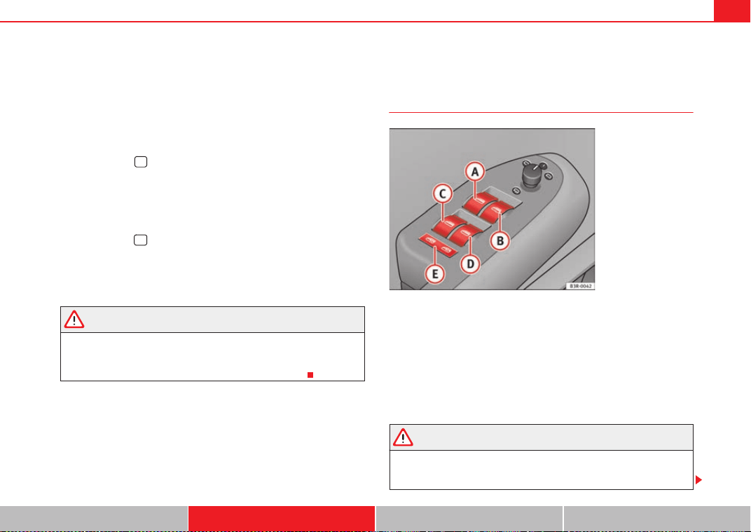
Unlocking and locking 109
Safety First Operating Instructions Practical Tips Technical Specifications
Deactivating the tow-away protection
– Open the door and pull out switch (with the symbol
) to one
side of the storage compartment, in the driver door ⇒ page 108,
fig. 79.
–Then lock the vehicle.
The LED on switch will light up when the interior monitoring is disabled.
The LED on the top of the driver door trim will also light up for about 3
seconds. When the vehicle is locked, the LED on the top of the driver door trim
will flash rapidly for about 3 seconds. About 30 seconds later it starts flashing
slowly. The interior monitoring is automatically enabled again the next time
the vehicle is locked.
The LED on switch will light up when the tow-away protection function is
disabled. The LED on the top of the driver door trim will also light up for about
3 seconds. When the vehicle is locked, the LED on the top of the driver door
trim will flash rapidly for about 3 seconds. The tow-away protection is auto-
matically enabled again the next time the vehicle is locked.
WARNING
Do not leave anyone (especially children) in the vehicle if it is locked from
the outside and the anti-theft security system is enabled, as the doors and
windows cannot then be opened from the inside. Locked doors could delay
assistance in an emergency, potentially putting lives at risk.
Electric windows
Control switches
Switches for front electric windows
Switch ⇒ fig. 80 for the driver door window
Switch for the front passenger door window.
Switches for rear electric windows
Switch for the rear left door window
Switch for the rear right door window
Safety switch
WARNING
• Always take the key with you when leaving the vehicle, even if you only
intend to be gone for a short time. This is particularly important if there are
children in the vehicle, as they might otherwise be able to start the engine
A
B
Fig. 80 Detail of the
driver door: Control
switches
A
A
A
B
A
C
A
D
A
E
ExeoST_EN.book Seite 109 Freitag, 3. September 2010 11:41 11
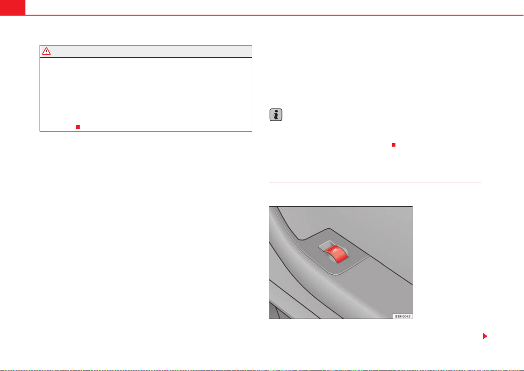
Unlocking and locking110
or use power-operated equipment (e.g. the electric windows), which could
cause injuries. The electric window switches are only disabled when the
driver door or the front passenger door is opened.
• Never close the windows in a careless or uncontrolled manner, as there
is a risk of causing injuries.
• When locking the vehicle from the outside, make sure that nobody is
inside the vehicle, as the windows cannot be opened from the inside in an
emergency.
Switches in the driver door
The driver can operate all the electric windows in the vehicle.
The electric windows are controlled by two-stage switches:
Opening the windows
– Press the switch as far as the first stop and hold it until the
window has moved to the desired position.
– Press the switch briefly to the second stop and the window will
automatically open all the way.
Closing the windows
– Pull the switch as far as the first stop and hold it until the window
has moved to the desired position.
– Pull the switch briefly to the second stop and the window will
automatically close all the way.
Safety switch
The safety switch ⇒ page 109, fig. 80 can deactivate the rear door
switches. The windows can only be operated from the rear when the safety
switch is pressed in.
The symbol
lights up on the safety switch when the electric windows in the
rear doors are disabled (switch not pressed in).
Note
The windows will work for about ten minutes after the ignition has been
switched off. The electric window switches are only disabled when the driver
door or the front passenger door is opened.
Switches on the front passenger's door and rear doors
Each of these doors has a switch for its own window.
The electric windows are controlled by two-stage switches:
WARNING (continued)
A
E
Fig. 81 Switch on front
passenger door
ExeoST_EN.book Seite 110 Freitag, 3. September 2010 11:41 11
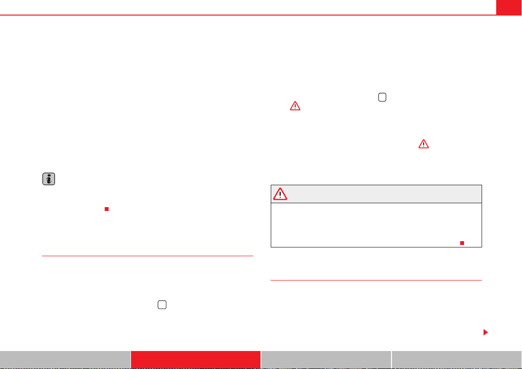
Unlocking and locking 111
Safety First Operating Instructions Practical Tips Technical Specifications
Opening the windows
– Press the switch as far as the first stop and hold it until the
window has moved to the desired position.
– Press the switch briefly to the second stop and the window will
automatically open all the way.
Closing the windows
– Pull the switch as far as the first stop and hold it until the window
has moved to the desired position.
– Pull the switch briefly to the second stop and the window will
automatically close all the way.
Note
The windows will work for about ten minutes after the ignition has been
switched off. The electric window switches are only disabled when one of the
front doors is opened.
Opening and closing the windows using the central locking
function
The windows can be opened or closed simultaneously when
the vehicle is unlocked or locked.
Opening the windows using the remote control
– Press and hold the unlock button on the remote control until
the windows reach the desired position.
Opening the windows using the ignition key
– Unlock the driver door with the key and hold the key in the unlock
position until all the windows are open.
Closing the windows using the remote control
– Press and hold the lock button until all windows are closed
⇒ .
Closing the windows using the ignition key
– Lock the driver door with the key and hold the key in the lock
position until all the windows are closed ⇒ .
The windows will stop moving when you release the remote control button or
turn the key back to its initial position in the door lock.
WARNING
• Be careful when closing the windows to ensure nobody is hurt.
• For safety reasons, you should only use the remote control open and
close functions within about 2 metres of the vehicle. To avoid injuries,
always keep an eye on the windows when pressing the button to close
them. The windows stop moving as soon as the button is released.
Possible malfunctions
Automatic open and close function not working
The automatic open and close function will not work if the battery has been
temporarily disconnected. The function can be restored as follows:
• Close the window as far as it will go by lifting and holding the window
switch.
ExeoST_EN.book Seite 111 Freitag, 3. September 2010 11:41 11
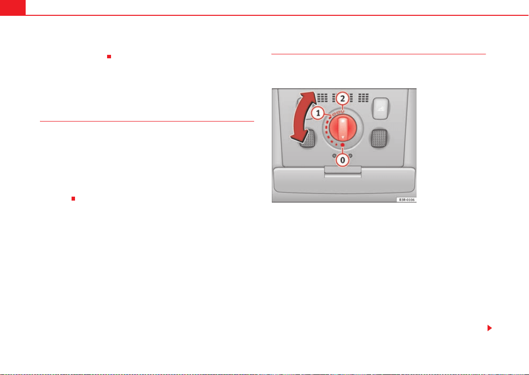
Unlocking and locking112
• Release the switch and then lift it again for one second. This will re-enable
the automatic function.
Sliding/tilting sunroof*
Description
The sliding/tilting sunroof is operated using the rotary knob ⇒ fig. 82. The
rotary knob for sliding the roof open can be adjusted to several different
settings (with click stops). This knob only works when the ignition is switched
on. The rotary knob must be in the position if you want to tilt the roof up
at the rear.
The sunroof will work for about ten minutes after the ignition has been
switched off. However, it is immediately disabled when one of the front doors
is opened.
Opening/Tilting
The sunroof will create less wind noise if it is opened in the
convenience position.
Convenience position
– Turn the control until it engages at position ⇒ fig. 82. The
sunroof will now only open as far as the convenience position
which means there is less wind noise.
Opening completely
– Turn the switch to position and hold it until the sunroof
reaches the desired position. This position can cause more wind
noise.
Tilting open
– Turn the control to position .
A
0
Fig. 82 Detail of head-
liner: Sliding/tilting
sunroof control
A
1
A
2
A
0
ExeoST_EN.book Seite 112 Freitag, 3. September 2010 11:41 11
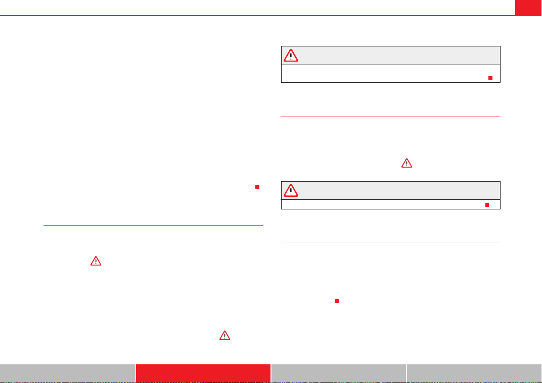
Unlocking and locking 113
Safety First Operating Instructions Practical Tips Technical Specifications
– With the control in position 0, press the control briefly to make
the roof tilt open all the way.
– To open the roof as far as an intermediate setting, press and hold
the control until the roof has moved to the desired position.
When you release the switch it will automatically spring back from position
to position .
The sliding sun blind in the headliner automatically opens when the sunroof
is slid open. If required, it can be closed by hand when the sunroof is closed.
It is advisable to close the sun blind when the vehicle is left standing in the
sun. It is important to remember to close the sunroof when parking the
vehicle or if it suddenly starts raining, especially when the sun blind is
closed.
For further information on the automatic close function, see ⇒ page 113.
Closing
Closing
– Turn the control to position ⇒ page 112, fig. 82 to close the
sunroof ⇒ .
Closing the sunroof from the tilt position
– Pull the specially formed rear end of the control and hold it until
the sunroof has moved down to the desired position.
–Pull the switch briefly to lower the sunroof automatically to the
fully closed position. If required, the sunroof can be stopped in
any position by briefly pulling the control again ⇒ .
WARNING
Take care when closing the sunroof. There is a risk of suffering injury. For
this reason, always take out the ignition key when leaving the vehicle.
Automatic close function
The sunroof can also be closed from outside the vehicle.
– Turn the key in the lock on the driver door and hold it in the lock
position or press the lock button on the remote control until the
sunroof has closed all the way ⇒ .
WARNING
Take care when closing the sunroof. There is a risk of suffering injury.
Solar sunroof*
The solar cells in the sunroof power the air conditioner fan.
The solar sunroof is operated in the same way as the normal sliding/tilting
sunroof.
The interior trim is fixed to the solar sunroof and cannot be opened and
closed separately.
A
2
A
1
A
0
ExeoST_EN.book Seite 113 Freitag, 3. September 2010 11:41 11
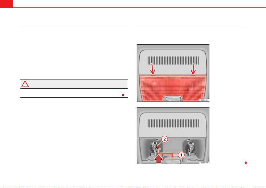
Unlocking and locking114
Emergency electrical activation
In an emergency it is possible to close the sunroof electroni-
cally.
The sliding sunroof mechanism is equipped with a safety cut-out. If
the roof should fail to close normally, it can be closed with the emer-
gency function.
– Turn the control to position ⇒ page 112, fig. 82.
– Pull on the control switch until the roof closes.
WARNING
Take care when closing the sunroof. There is a risk of suffering injury. For
this reason, always take out the ignition key when leaving the vehicle.
Closing the sunroof manually
The sunroof can be closed by hand if the electrical system
should fail to operate.
A
0
Fig. 83 Detail of head-
liner: Points for applying
screwdriver
Fig. 84 Detail of head-
liner: Crank handle for
manual operations
ExeoST_EN.book Seite 114 Freitag, 3. September 2010 11:41 11
Unlocking and locking 115
Safety First Operating Instructions Practical Tips Technical Specifications
– Carefully insert the flat end of a screwdriver (from the vehicle's
tool kit) at the rear of the glass cover on the interior light
⇒ page 114, fig. 83.
– Carefully lever off the glass cover.
– Take the crank handle from its mounting on the inside of the fuse
box cover ⇒ page 265.
– Insert the crank handle all the way into the hexagonal socket
⇒ page 114, fig. 84.
– Hold the crank handle in position and turn it to close the sunroof.
– Reinstall the glass cover: insert the plastic lugs first and then
press the cover upwards.
– Have the fault repaired.
Note
You can use the screwdriver handle to make it easier to turn the crank. Detach
the handle from the screwdriver and then fit the handle onto the crank.
A
1
A
2
ExeoST_EN.book Seite 115 Freitag, 3. September 2010 11:41 11
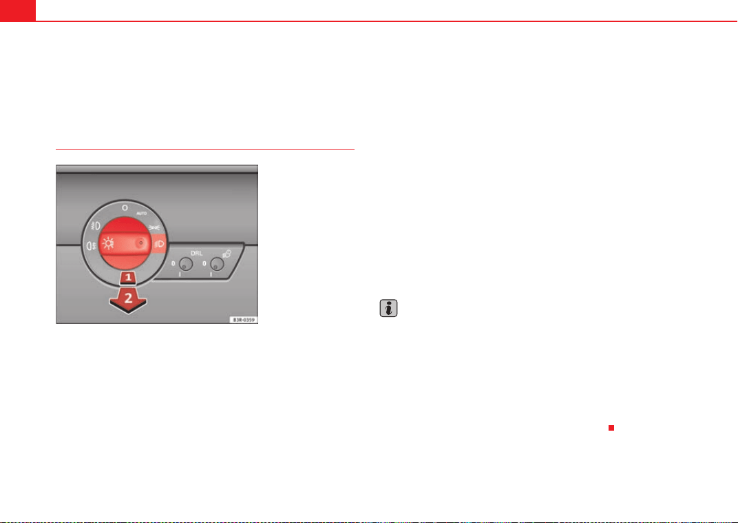
Lights and visibility116
Lights and visibility
Lights
Lights: switching on and off
Switching on the side lights
–Turn the light switch ⇒ fig. 85 to position
.
Switching on dipped or main beam headlights (driving lights)
Dipped beam headlights
– Turn the lights switch to position
.
Main beam headlights
– Turn the lights switch to position
.
– Press the main beam lever forward ⇒ page 123.
Switching off the lights
– Turn the light switch to position O.
Daytime running lights: In vehicles for countries where daytime running
lights are obligatory and in all vehicles with AFS headlights, daytime running
lights are turned on or off with the ignition. Daytime running lights have main
beam flashers, as usual, but not the dipped beam headlight function
The dipped beam headlights will only work with the ignition on. The head-
lights are automatically switched to side lights after the ignition has been
switched off.
If the side lights or the dipped beam headlights are turned on, the
symbol
will come on together with the lights switch.
Note
• If the lights are left on after the key has been taken out of the ignition lock,
a buzzer sounds when the driver door is opened.
• Observe all relevant legal requirements when using the signalling and
lighting systems described here.
•
Depending on weather conditions (cold or wet), the front lights, the fog
lights, the tail lights and the turn signals may be temporarily misted. This has
no influence on the useful life of the lighting system. By switching on the
lights, the area through which the beam of light is projected will quickly be
demisted. However, the edges may continue to be misted.
Fig. 85 Detailed view of
the dash panel: Light
switch
ExeoST_EN.book Seite 116 Freitag, 3. September 2010 11:41 11
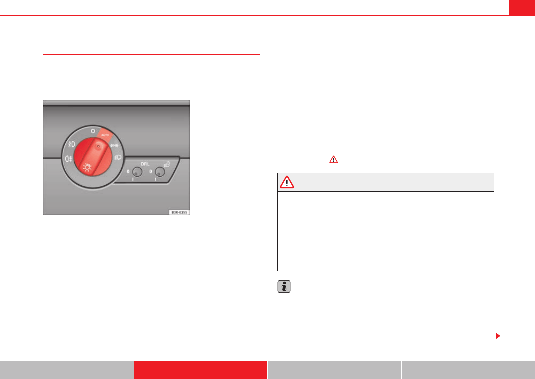
Lights and visibility 117
Safety First Operating Instructions Practical Tips Technical Specifications
Automatic headlight switch* (sensor-controlled)
If you set the light switch to “AUTO”, the dipped headlights
will switch on and off automatically according to the ambient
light level.
Turning on dipped beam headlights
– Turn the light switch ⇒ fig. 86 to the AUTO position.
Turning off dipped beam headlights
– Turn the light switch to position O.
The symbol on the switch lights up when the switch is in the AUTO position.
The dipped beams, side lights, tail lights and number plate lights come on
together when the headlights are switched on automatically.
When you are using the automatic headlights switch, you can also operate
the main beam headlights, however, please note the following: If you enable
the main beam headlights while using the automatic headlights function
during the day (e.g. when driving through a tunnel), but do not disable them
again, only the dipped beam headlights will come on the next time the lights
are automatically switched on. To be able to use the main beam headlights
again, you must first pull the main beam lever back to the "off" position and
then push it forward again to "on".
The side lights, headlights, fog lights and rear fog light can still be switched
on manually in the normal way by using lights switch ⇒ page 116.
The interior mirror is fitted with sensors that measure the ambient light. The
dipped beam headlights will be switched on automatically if the available
light drops below the factory preset value (for instance when driving through
a tunnel, etc.). The headlights switch off again automatically when the light
level increases ⇒ .
WARNING
• The automatic dipped beam headlights are only intended to assist the
driver. Automatic dipped beam headlights do not relieve the driver of his or
her responsibility to control them and turn off or turn on the lights manu-
ally according to weather or lighting conditions. The light sensors are, for
example, unable to detect rain and fog - you should therefore always switch
on the dipped beam headlights
manually in these conditions and when
driving after dark.
• Observe all relevant legal requirements when using the signalling and
lighting systems described here.
Note
• If automatic headlight switching is activated, when the ignition is turned
off the dipped beam headlights are turned off, and when the key is removed
from the ignition the side lights are turned off.
• If you have to attach any type of sticker on the windscreen, do not do so
in front of the sensors. Doing so could prevent the automatic dipped beam
Fig. 86 Detailed view of
the dash panel: Light
switch
ExeoST_EN.book Seite 117 Freitag, 3. September 2010 11:41 11
Lights and visibility118
headlight or anti-dazzle function from working correctly or even from working
at all.
• The warning symbol will appear on the instrument panel if a malfunc-
tion occurs ⇒ page 81.
• Observe all relevant legal requirements when using the signalling and
lighting systems described here.
Front fog lights
The light switch can also be used to turn on the front fog
lights.
Switching on the front fog lights
–Do ⇒ page 116, fig. 85 not turn the light switch to the symbol
.
– First turn the light switch to the position
or .
– Then pull the light switch out to the first stop .
The front fog light symbol next to the switch will light up when the front fog
lights are on.
Rear fog light
The light switch can also be used to turn on the rear fog light.
–Do ⇒ page 116, fig. 85 not turn the light switch to the symbol
.
– First turn the light switch
⇒ page 116, fig. 85 to the position
or .
– Then pull out the light switch to the second stop to switch on
the rear fog light.
The symbols and next to the switch will light up when the rear fog light
is switched on.
If you are towing a trailer or caravan equipped with a rear fog light on a vehicle
with a factory-fitted towing bracket*, only the rear fog light on the trailer or
caravan will light up.
Caution
To avoid dazzling the traffic behind you, the rear fog light should only be used
in accordance with legal regulations.
A
1
A
2
ExeoST_EN.book Seite 118 Freitag, 3. September 2010 11:41 11
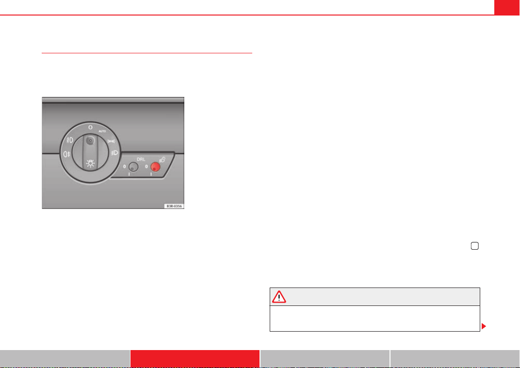
Lights and visibility 119
Safety First Operating Instructions Practical Tips Technical Specifications
Coming home and leaving home functions*
The coming home and leaving home functions are used to
light up the surroundings in the dark. The front fog lights, the
rear side lights and the number plate light switch on.
Activating the function
– Briefly press the knob ⇒ fig. 87 to release it from its set position.
– Turn the knob to position 1.
– Press the knob in again to prevent the setting from being
changed unintentionally.
Deactivating the function
– Briefly press the knob ⇒ fig. 87 to release it from its set position.
– Turn the knob to position 0.
– Press the knob in again to prevent the setting from being
changed unintentionally.
The coming home and leaving home functions are controlled by light sensors
in the interior mirror housing. The system will function when the following
requirements are met:
• The knob is set to position 1.
• The headlights and the ignition are switched off.
• Dark conditions; the sensors register little or no light.
Coming home
When the system is enabled and it is dark, the corresponding exterior lights
switch on as soon as the driver door is opened.
The exterior lights will stay on for up to a maximum of 2 minutes as long as
one of the doors or the tailgate is open.
The exterior lights stay on for about 30 seconds to light up the area around
the vehicle after all the doors and the tailgate have been closed.
This time interval is factory-set, but you can have it changed by a qualified
workshop to suit your own requirements (max. setting is 60 seconds).
Leaving home
The exterior lights are switched on when the vehicle is unlocked with the
button on the remote control key.
The exterior lights go out when the driver door is opened or after 60 seconds
when the vehicle locks itself again automatically ⇒ page 106.
WARNING
Before leaving the vehicle, remove the key from the ignition, as the lights
will not go out if the coming home function is activated. This will lead to
battery discharge and vehicle breakdown.
Fig. 87 Detailed view of
the dash panel: Coming
home and leaving home
functions
ExeoST_EN.book Seite 119 Freitag, 3. September 2010 11:41 11
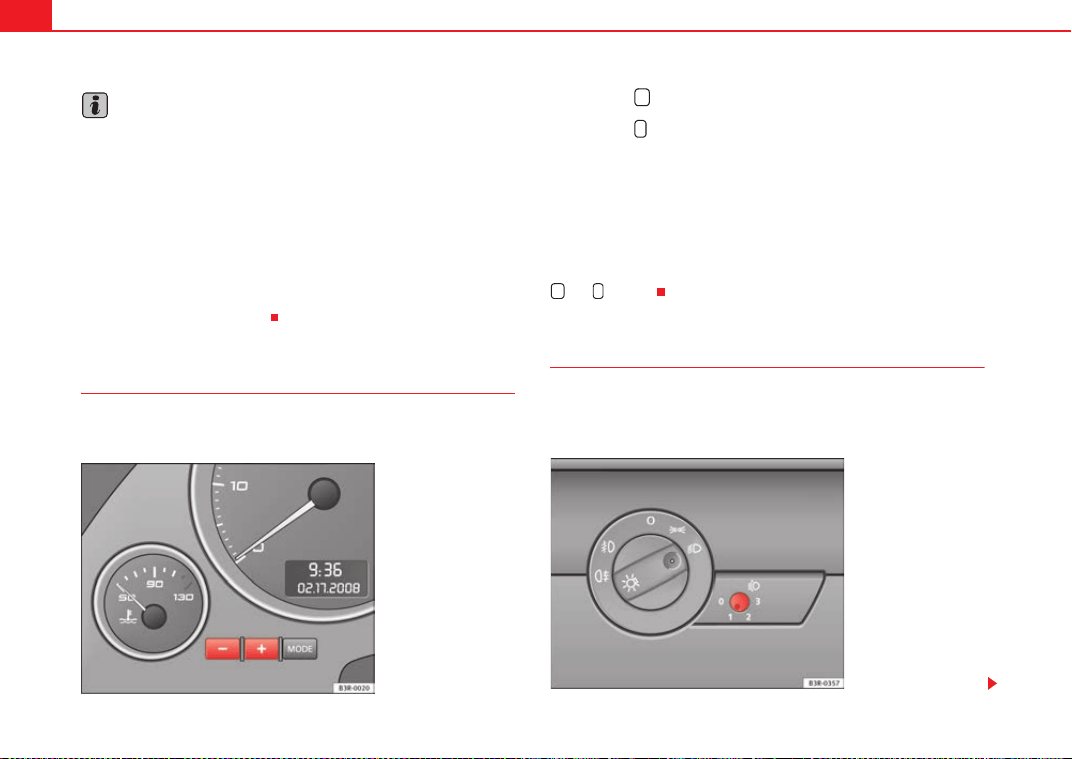
Lights and visibility120
Note
• If you always wish to use the coming home and leaving home functions,
you can leave them permanently switched on. As the system is controlled via
a photosensor, it will only work in dark conditions.
• Permanent use of the coming home and leaving home functions, particu-
larly on short journeys, will increase the load on the battery. To make sure the
battery is always sufficiently charged, occasionally drive longer distances.
• If the fog lights have been switched on by the coming home and leaving
home functions, they will always be switched off when you switch on the igni-
tion.
• Observe all relevant legal requirements when using the signalling and
lighting systems described here.
Instrument lighting
The brightness of the instrument lighting, displays and
centre console lighting can be varied as required.
– Press the button to increase the brightness.
– Press the button to reduce the brightness.
With the ignition switched on
The lighting of the digital displays will adjust automatically, depending on
the ambient light.
With the vehicle's lights switched on
When the vehicle's lights are switched on, the brightness of the instrument
lighting, displays and centre console lighting can be varied by pressing the
and buttons.
Headlight range control
When the dipped beam headlights are switched on, the range
of the headlights can be adjusted to suit the load of the
vehicle.
Fig. 88 Instrument panel
lighting
+
-
+ -
Fig. 89 Headlight range
control
ExeoST_EN.book Seite 120 Freitag, 3. September 2010 11:41 11
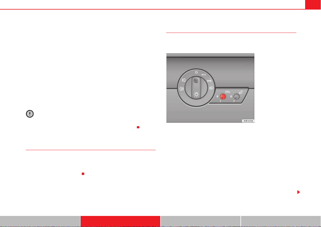
Lights and visibility 121
Safety First Operating Instructions Practical Tips Technical Specifications
– Briefly press the knob ⇒ page 120, fig. 89 to release it from
its set position.
– Turn the knob to the required setting.
– Press the knob in again to prevent the setting from being
changed unintentionally.
Settings
The settings roughly correspond to the following load conditions:
Two front occupants, luggage compartment empty
All seats occupied, luggage compartment empty
All seats occupied, luggage compartment loaded
Driver only, luggage compartment loaded
Caution
Always adjust the headlights to avoid dazzling oncoming traffic. Make sure
you lower the headlights when the vehicle is more heavily laden.
Dynamic headlight range control
On vehicles with xenon lamps, the headlights automatically adapt to suit the
load being carried when the ignition is switched on and when the vehicle is
moving, depending on the load of the vehicle and the type of driving (e.g.
when accelerating and braking).
Daytime running lights*
The daytime running lights turn on automatically when the
ignition is switched on.
Activating the function
– Briefly press the knob ⇒ fig. 90 to release it from its set position.
– Turn the knob to position 1.
– Press the knob in again to prevent the setting from being
changed unintentionally.
Deactivating the function
– Briefly press the knob ⇒ fig. 90 to release it from its set position.
– Turn the knob to position 0.
A
O
A
1
A
2
A
3
Fig. 90 Daytime running
lights switch
ExeoST_EN.book Seite 121 Freitag, 3. September 2010 11:41 11
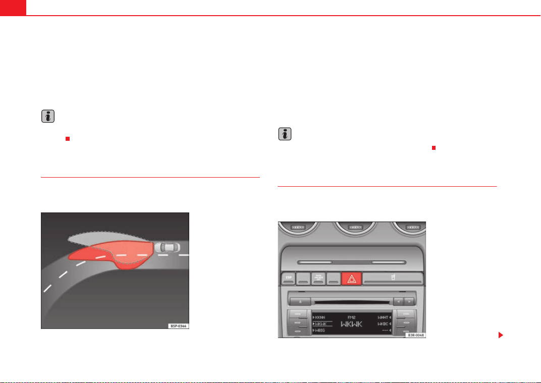
Lights and visibility122
– Press the knob in again to prevent the setting from being
changed unintentionally.
This button activates or deactivates the daytime running lights function. With
the function activated, when the ignition is switched on the daytime running
lights are turned on automatically.
Note
Please observe any relevant legal requirements which may apply in your
country.
Adaptive headlights* (for driving around bends)
When driving around bends, the headlights will light the
most important areas of the road.
The dynamic cornering light gives better illumination of the curve area and
the side of the road when driving around a bend ⇒ fig. 91. The dynamic
cornering light is controlled automatically depending on the speed and the
steering wheel angle.
The dipped beam headlights are regulated automatically when you drive
around a bend, depending on how far you turn the steering wheel. The two
main headlights move at different angles to avoid that the front of the vehicle
is left completely in the dark.
Note
The system operates from a speed of about 10 km/h.
Hazard warning lights
The hazard warning lights are used to draw the attention of
other road users to your vehicle in emergencies.
Fig. 91 Adaptive head-
lights when driving
Fig. 92 Centre console:
Switch for hazard warning
lights
ExeoST_EN.book Seite 122 Freitag, 3. September 2010 11:41 11
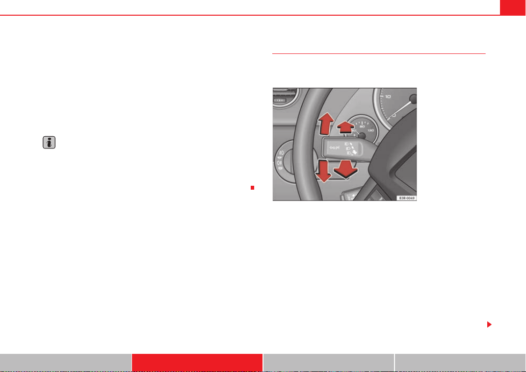
Lights and visibility 123
Safety First Operating Instructions Practical Tips Technical Specifications
–Press the switch ⇒ page 122, fig. 92 to switch the hazard
warning lights on or off.
All four turn signals flash simultaneously when the hazard warning lights are
switched on. The turn signal indicators
and the hazard warning light
indicator
flash at the same time. The hazard warning lights also work
when the ignition is switched off.
In an accident in which the airbags are triggered, the hazard warning lights
are switched on automatically.
Note
You should switch on the hazard warning lights to warn other road users, e.g.
• When reaching the tail end of a traffic jam
• If your vehicle breaks down or there is an emergency
• If your vehicle is being towed away or if you are towing another vehicle
Turn signal and main beam headlight lever
The turn signal and main beam headlight lever also operates
the parking lights and the headlight flasher.
The turn signal and main beam headlight lever has the following
functions:
Turn signals
– Move the lever all the way up to indicate right or all the way down
to indicate left ⇒ fig. 93.
– Move the lever up or down just as far as the point of resistance
and hold it there: the turn signals flash for as long as you hold
the lever (for instance when changing a lane).
– Move the lever briefly up or down as far as the point of resistance
and release it to signal briefly (the turn signals flash three times).
Fig. 93 Turn signal and
main beam headlight
lever
ExeoST_EN.book Seite 123 Freitag, 3. September 2010 11:41 11
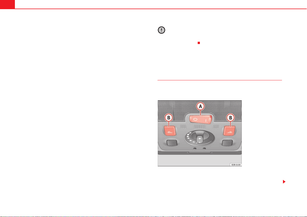
Lights and visibility124
Main beam headlights
– Press the lever forward to switch on the main beams.
– Pull the lever back towards you to switch the main beam head-
lights off again.
Headlight flasher
– Pull the lever towards the steering wheel to operate the flasher.
Parking light
– Switch the ignition off.
– Move the lever up or down to turn on the right or left-hand
parking lights respectively.
Notes on these functions
• The turn signals only work when the ignition is switched on. The turn
signal lamp
or flashes in the instrument panel when the turns signals
⇒ page 65 are working.
• The turn signals are cancelled automatically when the steering wheel is
returned to the straight-ahead position.
• The main beam headlights can only be switched on if the dipped beam
headlights are already on. The main beam headlight indicator lamp
then
comes on in the instrument panel.
• The headlight flasher comes on for as long as you pull the lever, even if no
other lights are switched on. The main beam headlight indicator lamp
then comes on in the instrument panel.
• When the parking lights are switched on, the headlight and the tail light
on one side of the vehicle light up with reduced intensity. The parking lights
will only work with the ignition off.
Caution
Never use the main beam headlights or the headlight flasher if this would
dazzle oncoming traffic.
Interior lights
Front interior lights and glove compartment light
The front interior light also incorporates the reading lights for
the driver and passenger.
The rocker switch ⇒ fig. 94 for the front interior light has the
following functions:
Fig. 94 Detail of head-
liner: front interior lights
A
A
ExeoST_EN.book Seite 124 Freitag, 3. September 2010 11:41 11
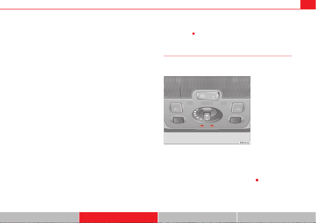
Lights and visibility 125
Safety First Operating Instructions Practical Tips Technical Specifications
Door light position
– Move switch to the centre position.
Interior light switched on
– Move switch to position I.
Interior light switched off
– Move switch to position O.
Front reading lights
– Press one of the switches to turn the left and right reading
lights on and off.
Glove compartment light
– Open the glove compartment on the front passenger side. The
glove compartment light will come on automatically if the side
lights or headlights are switched on, and will go out again when
the glove compartment is closed.
Footwell* and door lighting
– This is switched on when the doors are opened and off when they
are closed.
If the switch is in the courtesy light position, the interior light comes on auto-
matically when the vehicle is unlocked or the doors are opened. The light also
comes on when the key is pulled out of the ignition. The light turns off about
30 seconds after closing the doors. The interior light is switched off immedi-
ately when the vehicle is locked or when the ignition is switched on.
If a door is left open, the light is switched off after about 10 minutes to
prevent the battery from running flat.
The brightness of the lights is automatically adjusted by a dimmer when they
are switched on.
Ambient lighting*
The ambient lighting illuminates a number of important
controls.
The lights in the door handles come on automatically when the ignition is
switched on.
The lighting above the windscreen* also comes on when the side lights or
headlights are switched on. The centre console is illuminated from above.
The ambient lighting cannot be switched off manually.
A
A
A
A
A
A
A
B
Fig. 95 Detail of head-
liner: ambient lighting
ExeoST_EN.book Seite 125 Freitag, 3. September 2010 11:41 11
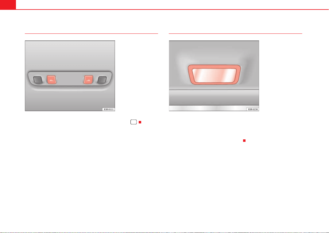
Lights and visibility126
Rear reading lights
The reading lights are switched on and off with the switches .
Luggage compartment lighting
The light is in the upper part of the luggage compartment.
The light ⇒ fig. 97 switches on automatically when the tailgate is opened.
The luggage compartment light is switched off automatically if the tailgate is
left open for more than about 10 minutes.
Fig. 96 Detail of head-
liner: rear reading lights
Fig. 97 Detailed view of
the top of the luggage
compartment: luggage
compartment lighting
ExeoST_EN.book Seite 126 Freitag, 3. September 2010 11:41 11
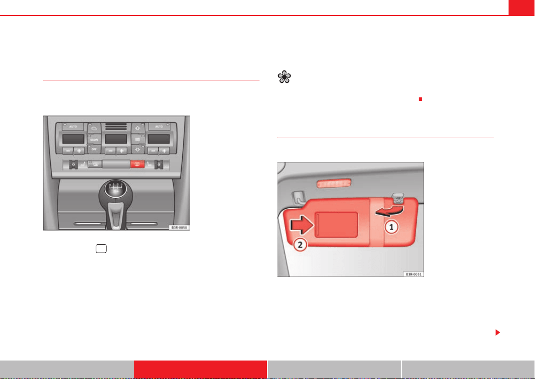
Lights and visibility 127
Safety First Operating Instructions Practical Tips Technical Specifications
Visibility
Heated rear window =
The rear window heating clears the rear window of condensa-
tion.
– Press button to switch the rear window heating on or off
⇒ fig. 98.
The heated rear window only works when the ignition is switched on. An indi-
cator lamp on the button lights up when the rear window heater is switched
on.
The heated rear window switches off automatically after about 10 minutes if
the outside temperature is above 0 °C.
Depending on the outside temperature, the exterior mirrors are also heated
while the heated rear window is turned on.
The exterior mirror heating is not activated in temperatures above approxi-
mately 20 °C.
For the sake of the environment
Switch off the heated rear window as soon as the rear window has demisted.
By saving electrical power you can also save fuel.
Sun visors
The sun visors can improve visibility and contribute to safety.
The sun visors for the driver and the front passenger can be pulled out of
their mountings in the centre of the vehicle and turned towards the doors
⇒ fig. 99.
The vanity mirrors in the sun visor have covers. On opening the cover , the
mirror light* located in the headliner is automatically switched on. The light
Fig. 98 Switch for heated
rear window
=
Fig. 99 Sun visor
A
1
A
2
ExeoST_EN.book Seite 127 Freitag, 3. September 2010 11:41 11
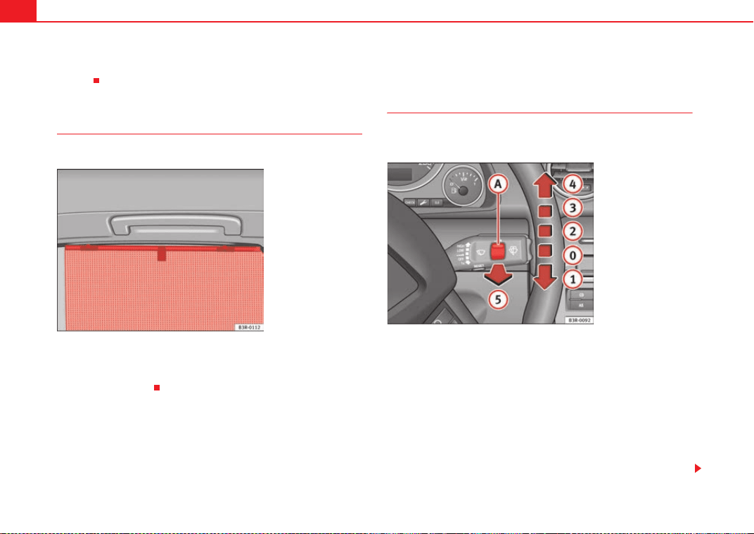
Lights and visibility128
switches itself off when the cover is closed and when the sun visor is pushed
back up.
Sun blind*
The rear side windows are fitted with sun blinds.
Sun blind (rear side windows)
– Pull out the blind and hook it into the hooks at the top of the door
frame ⇒ fig. 100.
Windscreen wipers
Windscreen wipers W
The windscreen wiper lever controls the windscreen wipers
and the automatic wash and wipe.
The windscreen wiper lever ⇒ fig. 101 has the following settings:
Short wipe
– Move the lever down to position to give the windscreen a
short wipe.
Intermittent wipe
/ Rain sensor * (activate)
– Move the lever up to position .
– Move the switch up or down to set the wiper intervals.
Fig. 100 Sun blind
extended to cover rear
side window
Fig. 101 Windscreen
wiper lever
A
1
A
2
A
A
ExeoST_EN.book Seite 128 Freitag, 3. September 2010 11:41 11
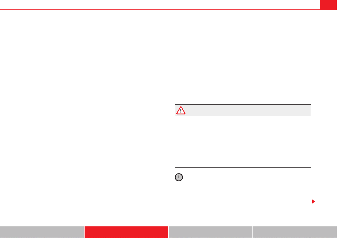
Lights and visibility 129
Safety First Operating Instructions Practical Tips Technical Specifications
– In vehicles equipped with a rain sensor*, you can move the
switch up and down to set the sensitivity of the rain sensor.
Slow wipe
– Move the lever up to position .
Continuous wipe
– Move the lever up to position .
Automatic wash and wipe
– Pull the lever towards the steering wheel, , to activate the
windscreen washer.
– Release the lever. The washer will stop and the wipers will keep
running for approximately 4 seconds.
Deactivating the windscreen wiper
– Pull the lever to basic position .
General notes
The washers and wipers will work only when the ignition is switched on.
If you stop briefly, e.g. at traffic lights, the wiper speed will automatically be
reduced. The rain sensor* will automatically be set to the intermittent wipe
function.
The windscreen washer jets are heated when the ignition is switched on.
The wiper intervals in the intermittent wipe setting are also varied automati-
cally according to the road speed (in addition to the manual delay setting).
When the lights are switched on you should only pull the lever briefly to wash
the windscreen, otherwise the headlight washers* will also be enabled. This
will use an unnecessary amount of fluid from the reservoir.
Rain sensor
The rain sensor* will only function in the intermittent wipe position. The inter-
mittent wipe function is enabled automatically when it starts to rain.
If the windscreen wiper lever was in the intermittent wipe position when the
ignition was off, the rain sensor will not activate until you reach a speed of 6
km/h.
Use switch to set the sensitivity of the rain sensor*.
If you have selected a high sensitivity level for the rain sensor the windscreen
wipers will react sooner to any moisture on the windscreen.
The wiper intervals in the intermittent wipe setting are also varied automati-
cally according to the road speed (in addition to the sensitivity setting).
WARNING
• For correct visibility and safe driving, the wiper must be in perfect
condition ⇒ page 218. Failure to do so could result in an accident.
• The rain sensor* is only intended to assist the driver. The driver is still
obliged to manually operate the windscreen wipers as required depending
on visibility.
• Do not use water-repellent coatings on the windscreen. In bad visibility
conditions such as light rain, low sun or when driving at night, these coat-
ings can cause increased dazzle, which is a serious safety hazard. Such
coatings can also cause the wiper blades to make noise.
Caution
• In the event of frost, check that the wiper blade has not frozen before acti-
vating the windscreen wipers. Should the windscreen wiper system be
enabled when the blade is frozen, this could damage it or even the wind-
screen wiper system motor.
A
A
A
3
A
4
A
5
A
0
A
A
ExeoST_EN.book Seite 129 Freitag, 3. September 2010 11:41 11
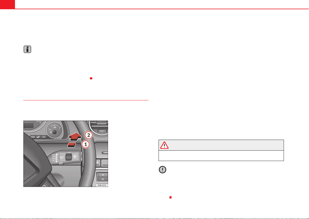
Lights and visibility130
• Make sure you switch off the windscreen wiper system (lever in position
0) before you use an automatic car wash. This will avoid inadvertent trig-
gering of the wipers and possible damage to the wiper system.
Note
• Check that the washer fluid reservoir is full before starting a long journey.
Fill the reservoir ⇒ page 236.
• Worn or dirty wiper blades can cause smearing on the glass which can
also impair the effectiveness of the rain sensor*. Check the condition of wind-
screen wiper blades at regular intervals.
Rear window wiper \
The windscreen wiper lever also operates the rear window
wiper and the automatic wash/wipe.
The rear window wiper and the automatic wash/wipe system are
switched on as follows:
Intermittent wipe
– Push the windscreen wiper lever forwards until it clicks into the
first position ⇒ fig. 102 . The rear window wiper will wipe the
window approximately every 4 seconds.
Automatic wash/wipe
\
– Push the lever forwards to position . The rear window wiper
will work for the time you hold the lever in this position.
– Release the lever. The rear window wiper will keep working for
approximately 4 seconds.
Deactivating the interval wipe function
– Pull the lever backwards until it returns to its original position.
The rear window wiper will start working automatically if reverse gear is
engaged while the windscreen wipers are switched on.
WARNING
For correct visibility and safe driving, the wiper must be in perfect condition
⇒ page 218. Failure to do so could result in an accident.
Caution
In icy conditions, always check that the wiper blades are not frozen to the
glass before using the windscreen wipers/rear window wiper. The windscreen
wiper blades and even the windscreen wiper motor could be damaged if you
start the windscreen wipers/rear window wiper with the blades frozen to the
glass.
Fig. 102 Windscreen
wiper lever
A
1
A
2
ExeoST_EN.book Seite 130 Freitag, 3. September 2010 11:41 11
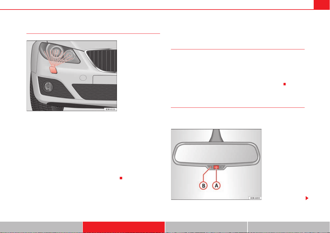
Lights and visibility 131
Safety First Operating Instructions Practical Tips Technical Specifications
Headlight washer system
With the lights switched on, operate the automatic wash and wipe
⇒ page 128, fig. 101 , and keep the lever pulled towards you for
at least 1 second.
The headlight washer jets come out of the bumper automatically (under water
pressure) ⇒ fig. 103.
Clean off dirt (insects, etc.) from the lenses at regular intervals, for instance
when filling the tank.
To ensure that the system works properly in winter, keep the nozzle holders
free of snow and remove any ice with a de-icer spray.
Rear view mirrors
Interior mirror with manual anti-dazzle setting
Normal setting
– Point the lever at the bottom of the mirror forwards.
Anti-dazzle setting for the interior mirror
– Point the lever at the bottom of the mirror to the rear.
Interior mirror with automatic anti-dazzle adjustment*
The automatic anti-dazzle function can be switched on and off
as desired.
Fig. 103 Headlight with
extended washer jet
A
5
Fig. 104 Interior mirror
with anti-dazzle setting:
Indicator lamp and on/off
switch
ExeoST_EN.book Seite 131 Freitag, 3. September 2010 11:41 11
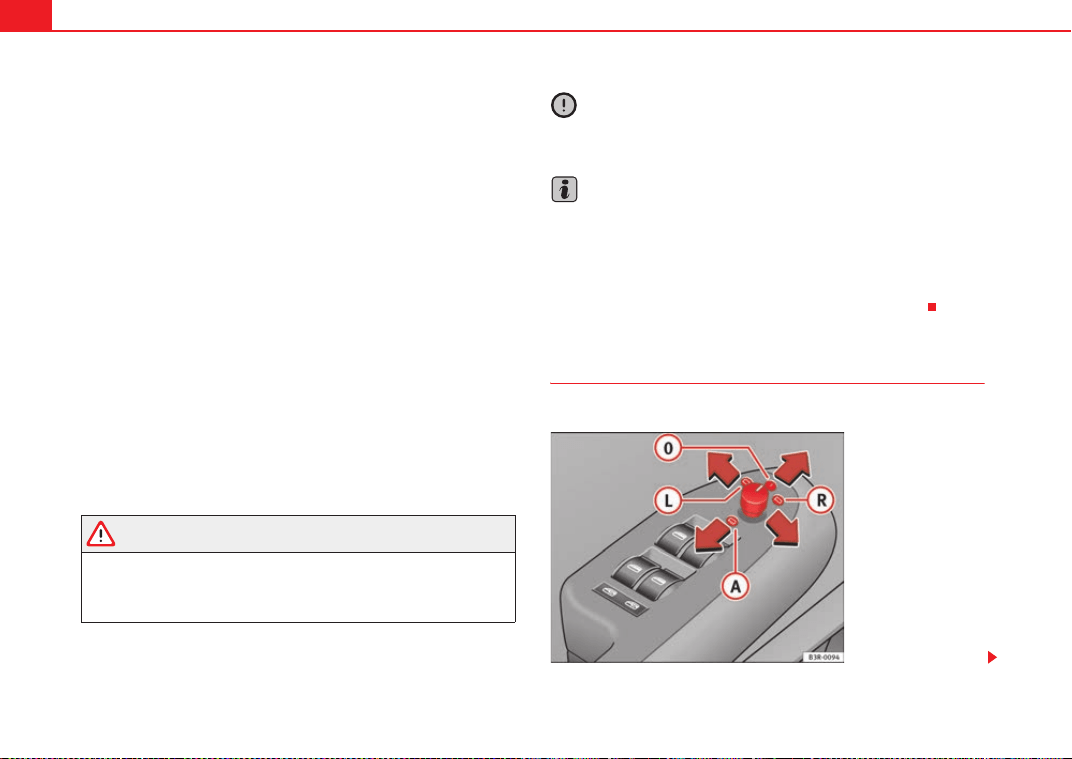
Lights and visibility132
Switching off the anti-dazzle function
–Press button ⇒ page 131, fig. 104. Indicator lamp goes
off.
Switching on the anti-dazzle function
–Press button ⇒ page 131, fig. 104. Indicator lamp turns
on.
Anti-dazzle function
The anti-dazzle function is activated every time the ignition is switched on.
The green indicator lamp lights up in the mirror housing.
When the anti-dazzle function is enabled, the interior mirror will darken auto-
matically according to the amount of light it receives. The anti-dazzle function
is disabled if:
• the interior lighting is switched on
• reverse gear is engaged
Sensors for automatic headlights*
When the light switch is set to the AUTO position, the dipped beam head-
lights are switched on and off automatically according to the ambient light
level with the aid of the sensors located in the interior mirror ⇒ page 117.
WARNING
Electrolyte fluid can leak from a broken mirror. This fluid can cause irrita-
tion to the skin, eyes and respiratory organs. Wash thoroughly with clean
water should you come into contact with this fluid. Seek medical assist-
ance if needed!
Caution
Electrolyte fluid leaking from a broken mirror can cause damage to plastic
surfaces. Use a sponge or similar to remove the fluid as soon as possible.
Note
• The interior mirror automatic anti-dazzle function* will only work properly
if the sun blind* for the rear window is retracted and if there are no other
objects preventing light from reaching the mirror.
• If you have to stick any type of sticker on the windscreen, do not do so in
front of the sensors. Doing so could prevent the automatic headlight or anti-
dazzle function from working correctly or even from working at all.
Exterior mirrors
The exterior mirrors are adjusted electrically.
A
A
A
B
A
A
A
B
Fig. 105 Detailed view of
the armrest: Adjuster
knob
ExeoST_EN.book Seite 132 Freitag, 3. September 2010 11:41 11
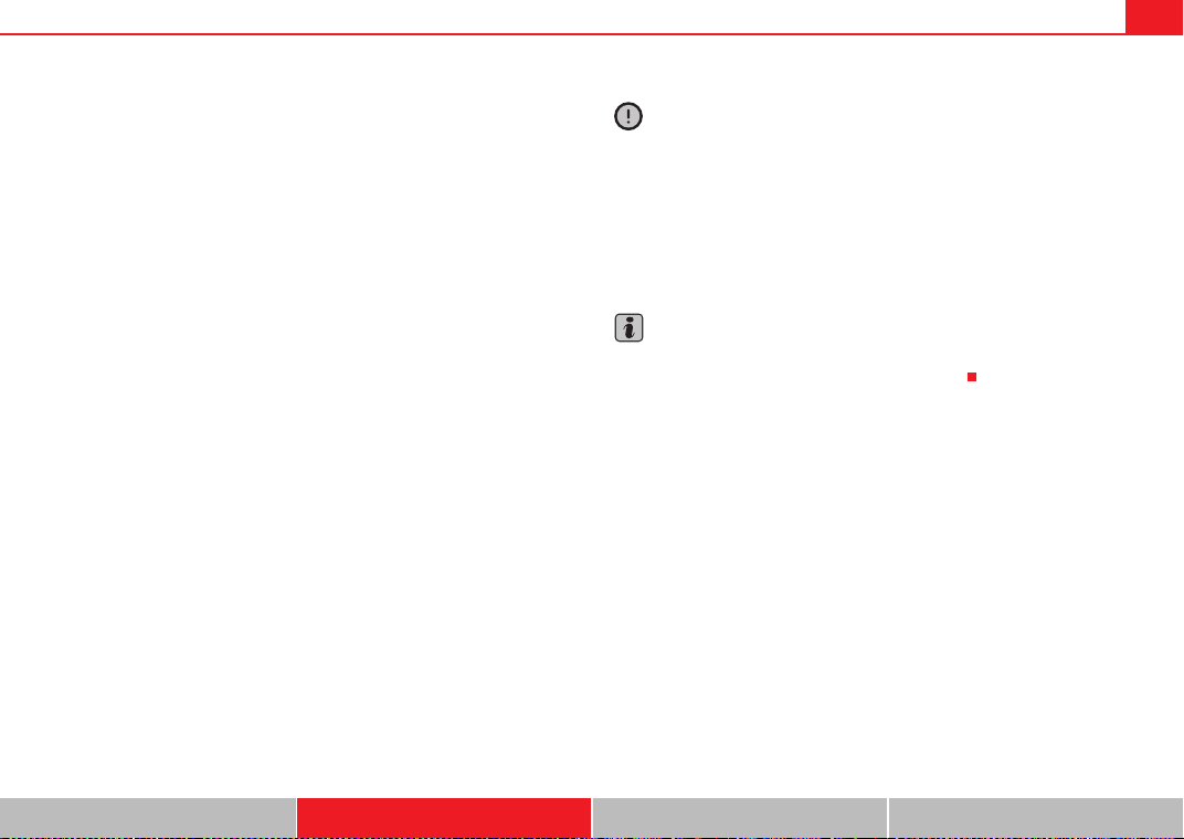
Lights and visibility 133
Safety First Operating Instructions Practical Tips Technical Specifications
Adjusting the exterior mirrors
– Turn the adjuster knob to position ⇒ page 132, fig. 105 (left
exterior mirror) or position (right exterior mirror).
– Move the knob as required to adjust the exterior mirror for a good
view behind you.
Retracting both exterior mirrors
– Turn the knob to position .
It is advisable to fold the exterior mirrors, for example when parking or when
driving through narrow spaces.
Heated mirrors
The mirrors are heated (depending on the outside temperature) when the
heated rear window ⇒ page 127 is switched on.
The exterior mirror heating is not activated in temperatures above approxi-
mately 20 °C.
Memory for exterior mirrors*
In vehicles with memory function for the driver seat, the setting of the exterior
mirrors is automatically stored together with the seat position ⇒ page 138.
Tilting function for exterior mirror on the passenger side* (only if equipped
with memory for exterior mirrors)
When reverse gear is engaged, the mirror surface tilts slightly downwards,
provided the mirror control is switched to the exterior mirror on the passenger
side (knob in position ⇒ page 132, fig. 105). This provides a better view
of the kerb when parking.
The mirror returns to its original position as soon as reverse gear is disen-
gaged and the vehicle is driven forwards at a speed above 15 km/h, or when
the mirror control is turned to position or to the neutral position .
Caution
• Rear view convex or aspheric* mirrors increase the field of vision,
although objects appear smaller and further away in the mirrors. Therefore,
you should not rely on these mirrors for judging the distance of vehicles
behind.
• If one of the mirror housings is knocked out of position (e.g. when
parking), the mirrors must first be fully retracted with the electric control. Do
not readjust the mirror housing by hand, as this will interfere with the mirror
adjuster function.
Note
If the electrical adjustment ever fails to operate, the mirrors can be adjusted
by hand by lightly pressing the edge of the mirror glass.
A
L
A
R
A
A
A
R
A
L
A
0
ExeoST_EN.book Seite 133 Freitag, 3. September 2010 11:41 11
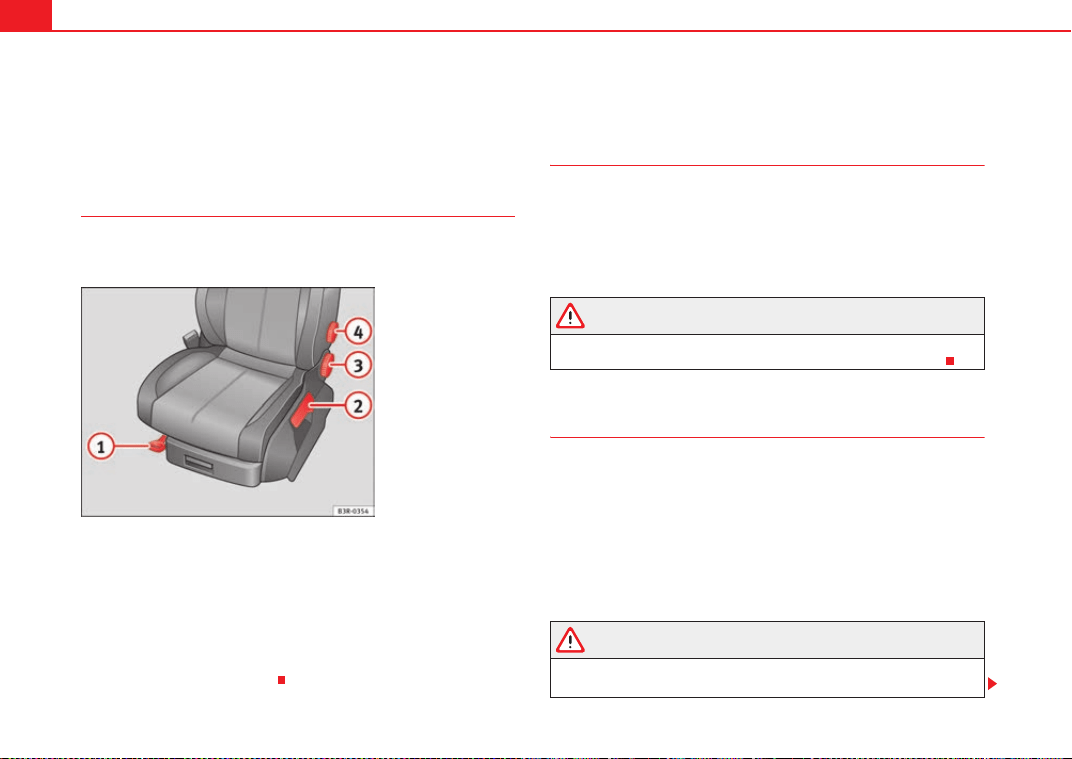
Seats and storage compartments134
Seats and storage compartments
Manual adjustment of the front seats
Seat adjuster controls
There are several seat adjustment functions for your conven-
ience
Some of the equipment listed is only fitted on certain models or is an optional
extra.
Control switches
Moving the seat backwards or forwards
Raising/lowering the seat
Adjusting the backrest angle
Adjusting the lumbar support
Moving the seats forwards and backwards
– Lift the lever ⇒ fig. 106 and move the seat to the desired
position.
– Then release the lever and move the seat further until the
catch engages.
WARNING
The driver seat must only be moved forwards and backwards when the
vehicle is at a standstill. Failure to do so could result in an accident.
Adjusting the seat height*
Raising the seat
– Pull the lever ⇒ fig. 106 up repeatedly until the seat is in the
desired position.
Lowering the seat
– Press the lever down repeatedly until the seat is in the
desired position.
WARNING
• The height of the driver seat must not be adjusted while driving. Failure
to do so could result in an accident.
Fig. 106 Adjuster
controls on driver seat
A
1
A
2
A
3
A
4
A
1
A
1
A
2
A
2
ExeoST_EN.book Seite 134 Freitag, 3. September 2010 11:41 11
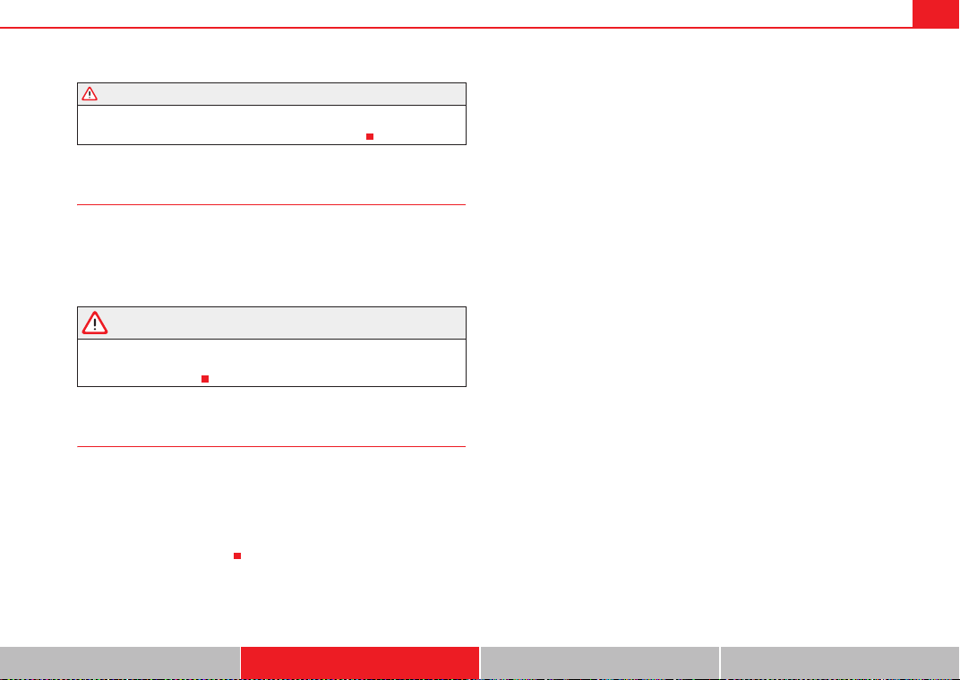
Seats and storage compartments 135
Safety First Operating Instructions Practical Tips Technical Specifications
• Be careful when adjusting the seat height. Injuries can be caused if the
seat height is adjusted without due care and attention.
Adjusting the backrest angle
– Lean forwards to take your weight off the backrest.
– Turn the adjuster wheel ⇒ page 134, fig. 106 to set the angle
of the backrest as required.
WARNING
The front backrests must not be reclined for driving. Otherwise, seat belts
and the airbag system might not protect as they should, with the subse-
quent danger of injury.
Adjusting lumbar support*
– Do not exert any pressure on the backrest and turn adjuster
wheel ⇒ page 134, fig. 106 to adjust lumbar support.
As you make the adjustments, the curvature of the cushioned area of the
lumbar region becomes more or less acute. In this way, it adapts to the
natural curvature of the spine.
WARNING (continued)
A
3
A
4
ExeoST_EN.book Seite 135 Freitag, 3. September 2010 11:41 11
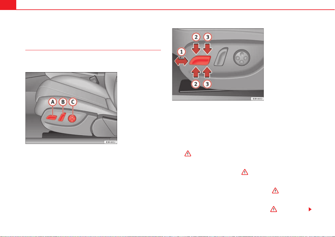
Seats and storage compartments136
Electric adjustment of front seats*
Adjusting the seat
The arrangement of the switches corresponds with the design
of the seats.
The adjustment switches for the seat and backrest correspond with
the layout, design and operation of the seat. The seats can be
adjusted merely by pressing the corresponding switch in the
required direction.
Moving the seat forwards / backwards
–Press switch ⇒ fig. 107 forwards or backwards ⇒ fig. 108
⇒ .
Raising/lowering the seat
– Press switch up or down ⇒ .
Raising/lowering the front part of the seat
– Press the front of switch up or down ⇒ .
Raising/lowering the rear part of the seat
– Press the rear of switch up or down ⇒ .
Fig. 107 Front seat:
Adjuster controls
Fig. 108 Front seat: Seat
adjustment switches
A
A
A
1
A
A
A
A
A
2
A
A
A
3
ExeoST_EN.book Seite 136 Freitag, 3. September 2010 11:41 11
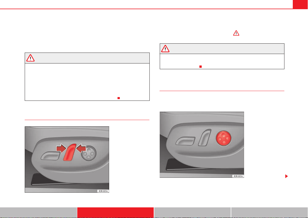
Seats and storage compartments 137
Safety First Operating Instructions Practical Tips Technical Specifications
Control switches
Seat adjustment
Backrest adjustment
Lumbar support*
WARNING
• The electrical seat adjustment also works when the ignition is off or
when the key is not in the ignition. To avoid accidental injuries, never leave
children unattended in the vehicle.
• For safety reasons, the seat must only be adjusted when the vehicle is
at a standstill. Failure to do so could result in an accident.
• Be careful when adjusting the seat height. Injuries can be caused if the
seat height is adjusted without due care and attention.
Adjusting the backrest angle
– Press the button in the appropriate direction of the arrow
⇒ fig. 109 to adjust the backrest ⇒ .
WARNING
The front backrests must not be reclined for driving. Otherwise, seat belts
and the airbag system might not protect as they should, with the subse-
quent danger of injury.
Lumbar support*
The lumbar support can be adjusted to fit the natural curve of
the spine.
A
A
A
B
A
C
Fig. 109 Front seat: Back-
rest adjuster switch
Fig. 110 Front seat:
Adjuster switch for lumbar
support
ExeoST_EN.book Seite 137 Freitag, 3. September 2010 11:41 11
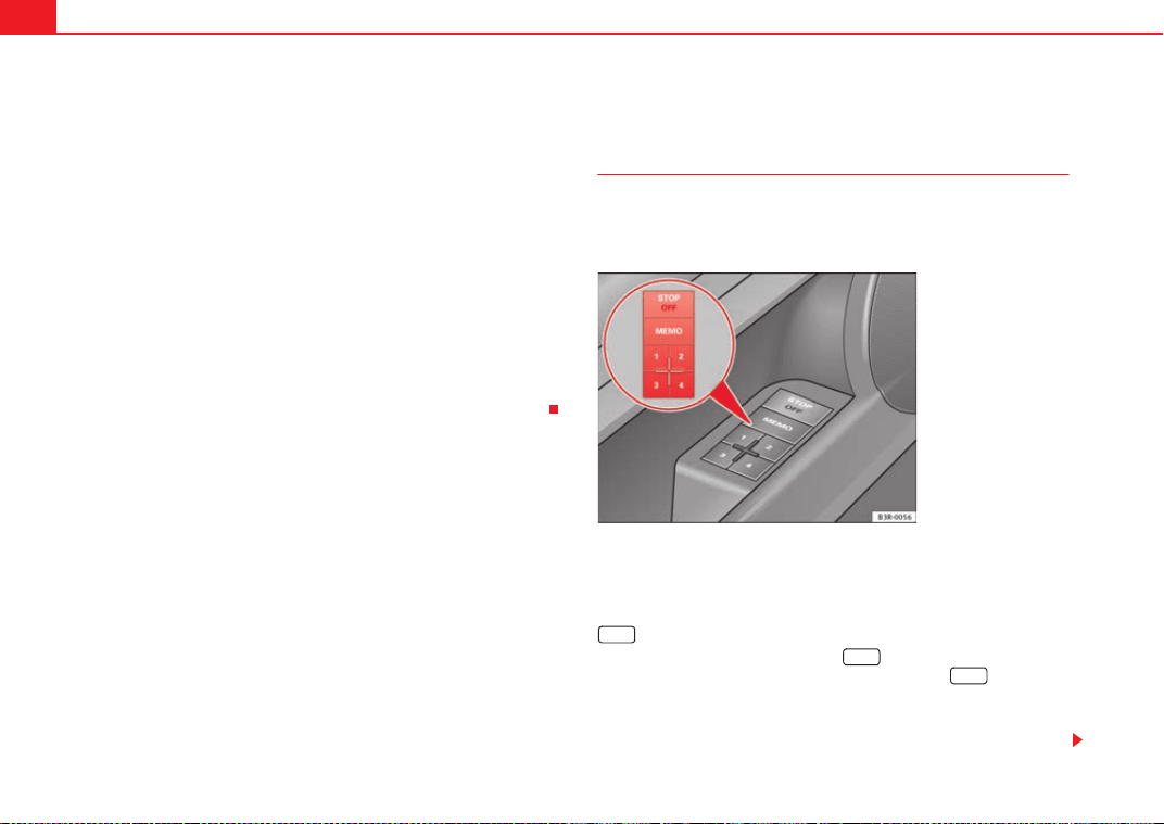
Seats and storage compartments138
Adjusting the contour
– Press the front part of the adjuster switch ⇒ page 137, fig. 110
to increase the contour of the lumbar support.
– Press the rear part of the adjuster switch to decrease the contour
of the lumbar support.
Adjusting the height
– Press the top part of the adjuster switch to move the contour
upwards.
– Press the bottom part of the adjuster switch to move the contour
down.
The lumbar support provides effective support for the natural curvature of the
spine to give a more relaxed seating position, especially on long journeys.
Driver seat memory*
Description
The memory buttons in the driver door can be used to store
and recall up to four different positions for the driver seat and
exterior mirrors.
Memory buttons
Using memory buttons 1, 2, 3 and 4 ⇒ fig. 111, you can store and recall the
seat and exterior mirror positions for up to four different drivers.
button
The seat memory will be disabled if the button is in the up position
(press and release). The word
/&& will light up next to the button (only
visible when the lights are switched on).
The stored settings will all remain in the memory. However, the seat and the
exterior mirrors can now only be adjusted using the conventional electrical
Fig. 111 Driver door:
Memory system
STOP
STOP
STOP
ExeoST_EN.book Seite 138 Freitag, 3. September 2010 11:41 11
Seats and storage compartments 139
Safety First Operating Instructions Practical Tips Technical Specifications
adjustment. Use of the button is recommended to disable the memory
system when the vehicle is being driven temporarily by a different driver
whose settings do not need to be stored in the memory.
Note
You can also use the remote control to call up the stored settings
⇒ page 140.
Storing settings
The button must be in its down position (pressed in) before
you can store the desired settings.
– Adjust the driver seat as required ⇒ page 136.
– Adjust both exterior mirrors ⇒ page 132.
– Press and hold the button. At the same time, press one of
the memory buttons for at least a second.
– Release both buttons. The setting is now stored on the selected
memory button.
Any new setting selected automatically cancels the existing setting stored on
the memory button. It is best to begin with memory button No. 1 for the first
driver and then assign the other memory buttons to each subsequent driver.
The seat and mirror positions are stored when the vehicle is locked with the
remote control and are assigned to the remote control key. The exterior
mirrors adjust automatically to the previous position when you unlock the
vehicle; the driver seat adjusts automatically when you open the driver door.
However, this does not delete the settings stored in memory buttons 1 to 4.
These settings can be enabled at any time.
Activating settings
Stored settings can be recalled using either the memory
buttons or the remote control (remote control key).
Using the memory buttons
– If the driver door is open, press the desired memory button
briefly.
– If the driver door is closed, press and hold down the appropriate
memory button until the seat and exterior mirrors reach their
programmed positions.
Using the remote control
– Unlock the vehicle using the remote control and open the driver
door within the next ten minutes.
The seat adjustment will have to be called up using the memory buttons if the
driver door is not opened within 10 minutes after unlocking the vehicle with
the remote control.
WARNING
• For safety reasons, the seat must only be adjusted when the vehicle is
at a standstill. Failure to do so could result in an accident.
• In an emergency, the memory function can be stopped at any time by
pressing the STOP button or by briefly pressing any of the memory
buttons.
STOP
STOP
MEMO
ExeoST_EN.book Seite 139 Freitag, 3. September 2010 11:41 11
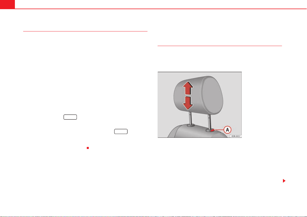
Seats and storage compartments140
Assigning remote control keys
The key must be assigned to a memory button so that the
positions stored in the memory can also be recalled using the
remote control key.
Assigning the remote control key to a memory button
– Using the memory button, recall the settings that are to be
programmed onto the key.
– Keeping the memory button pressed down, press the unlock
button on the remote control key within 10 seconds.
– Wait for about 2 seconds before releasing the memory button.
Deleting assignment of the remote control key to the memory
button
– Press and hold the button and press the unlock button on
the remote control key within 10 seconds.
– Wait for about 2 seconds before releasing the button.
The previous settings are automatically cancelled when the keys are re-
assigned to different memory buttons.
Head restraints
Front head restraints
In combination with properly worn seat belts, the head
restraints offer effective protection, provided they are prop-
erly adjusted to suit the height of the occupant.
Raising the head restraint
– Take hold of the sides of the head restraint with both hands.
– Pull up the head restraint.
Lowering the head restraint
– Press button and lower the head restraint.
MEMO
MEMO
Fig. 112 Front seats:
Head restraints
A
A
ExeoST_EN.book Seite 140 Freitag, 3. September 2010 11:41 11
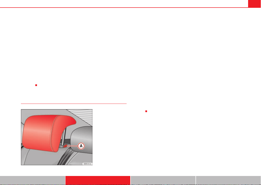
Seats and storage compartments 141
Safety First Operating Instructions Practical Tips Technical Specifications
Removing the head restraints
– Pull the head restraint up as far as it will go.
– Press button and pull out the head restraint.
Fitting the head restraint
– Insert the head restraint in its guides until it clicks into place.
Press button and lower the head restraint.
The height of the head restraints is adjustable. They should be set to suit the
height of the occupant. In combination with the seat belts, the head
restraints offer effective protection, provided they are properly adjusted.
For best protection, the top of the head restraint should be at least at eye level
or higher.
Head restraints on the side rear seats
Raising the head restraint
– Take hold of the sides of the head restraint with both hands.
– Pull the head restraint up as far as it will go.
Lowering the head restraint
– Press button ⇒ fig. 113 and lower the head restraint.
Removing the head restraint
– Pull the head restraint up as far as it will go.
– Press button ⇒ fig. 113 and pull out the head restraint.
Fitting the head restraint
– Insert the head restraint in its guides until it clicks into place.
Press button and lower the head restraint.
When the rear seats are not occupied, the head restraints should be moved
to the lowest position so that they do not obstruct the driver's field of
vision.
A
A
A
A
Fig. 113 Outer rear seats:
Head restraints
A
A
A
A
A
A
ExeoST_EN.book Seite 141 Freitag, 3. September 2010 11:41 11
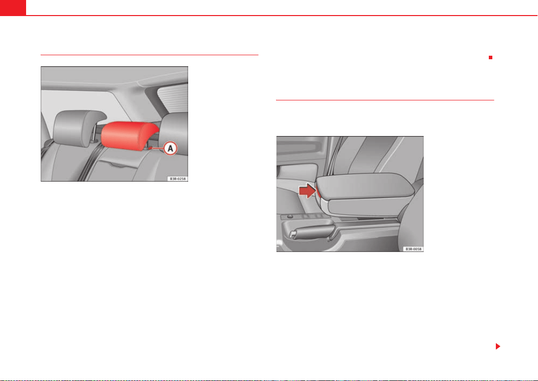
Seats and storage compartments142
Rear seat central head restraint
Raising the head restraint
– Take hold of the sides of the head restraint with both hands.
– Pull the head restraint up as far as it will go.
Lowering the head restraint
–Press button ⇒ fig. 114 and lower the head restraint.
Removing the head restraint
– Pull the head restraint up as far as it will go.
–Press button ⇒ fig. 114 and pull out the head restraint.
Fitting the head restraint
– Insert the head restraint in its guides until it clicks into place.
Press button and lower the head restraint.
When the rear seats are not occupied the head restraints should be moved to
the lowest position so that they do not obstruct the driver's field of vision.
Armrests
The armrest can be adjusted to several positions and incorpo-
rates a storage compartment.
Adjusting the armrest
– To adjust the position of the armrest, fold the armrest all the way
down.
– Then lift the armrest gradually until it engages in the desired
position.
Opening the storage compartment
– Press the release lever ⇒ fig. 115.
Fig. 114 Centre rear seat:
Head restraints
A
A
A
A
A
A
Fig. 115 Armrest
between the driver seat
and front passenger seat
ExeoST_EN.book Seite 142 Freitag, 3. September 2010 11:41 11
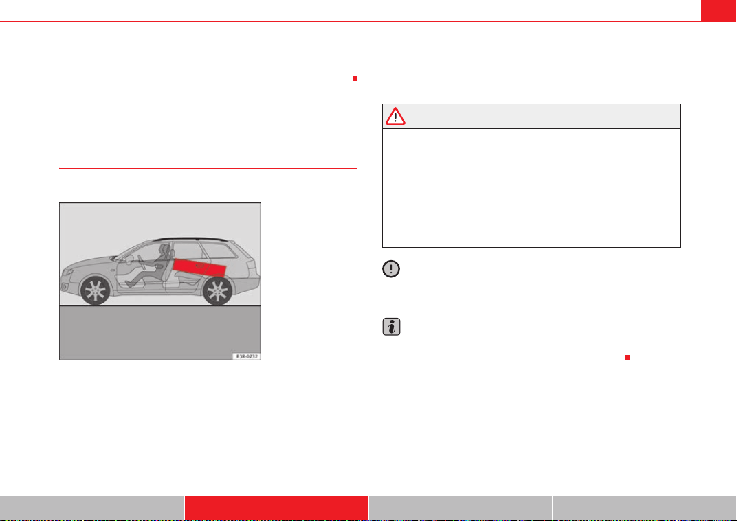
Seats and storage compartments 143
Safety First Operating Instructions Practical Tips Technical Specifications
Please note that the armrest can restrict the driver's movements when it is
lowered. The armrest should therefore be raised when driving in city traffic.
Luggage compartment
Loading the luggage compartment
Loads in the luggage compartment should be safely secured.
To maintain safe handling on the road, please observe the following
points:
– Distribute the load evenly.
– Position heavy items as far forward as possible ⇒ fig. 116.
– Secure the load with a luggage net* or with non-elastic straps
secured to the fastening rings ⇒ page 144.
WARNING
• Unsecured objects in the luggage compartment can suddenly shift and
cause changes in the handling of the vehicle.
• In an accident or a sudden manoeuvre, loose objects in the passenger
compartment can be flung forward and might injure vehicle occupants.
• Always keep all objects in the luggage compartment and use appro-
priate grips to secure them, particularly in the case of heavy objects.
• When you transport heavy objects, always bear in mind that a change
of the centre of gravity can also cause changes in vehicle handling.
• Please refer to the notes on ⇒ page 7.
Caution
Make sure that no hard objects chafe against the wires of the heating element
in the rear window and damage them.
Note
The tyre pressure must be adjusted according to the load. If necessary,
consult the tyre pressure label on the door pillar ⇒ page 245.
Fig. 116 Position heavy
items as far forward as
possible.
ExeoST_EN.book Seite 143 Freitag, 3. September 2010 11:41 11
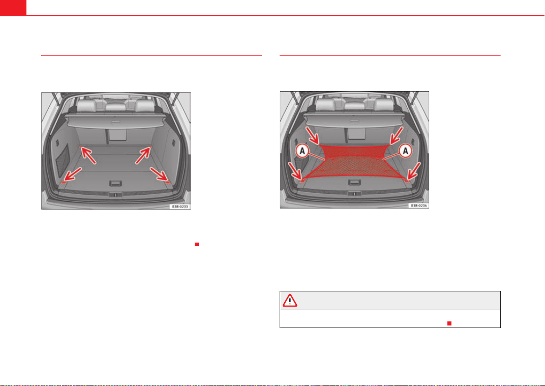
Seats and storage compartments144
Fastening rings
There are four fastening rings in the luggage compartment,
which can be used to secure loads.
– Use the fastening rings to secure the load ⇒ fig. 117 -arrows-.
– Please refer to the safety notes ⇒ page 17.
Luggage net*
The luggage net can be used to secure and retain light items
in the luggage compartment.
Luggage net
– Secure the luggage net to the four fastening rings -arrows-
⇒ fig. 118.
The luggage net can be attached to the fastening rings in the bottom of the
luggage compartment panel.
WARNING
The luggage net should only be used to hold objects weighing up to 5 kg.
Heavier objects cannot be safely secured (risk of injury).
Fig. 117 Location of
fastening rings in luggage
compartment
Fig. 118 Stretched
luggage net
ExeoST_EN.book Seite 144 Freitag, 3. September 2010 11:41 11
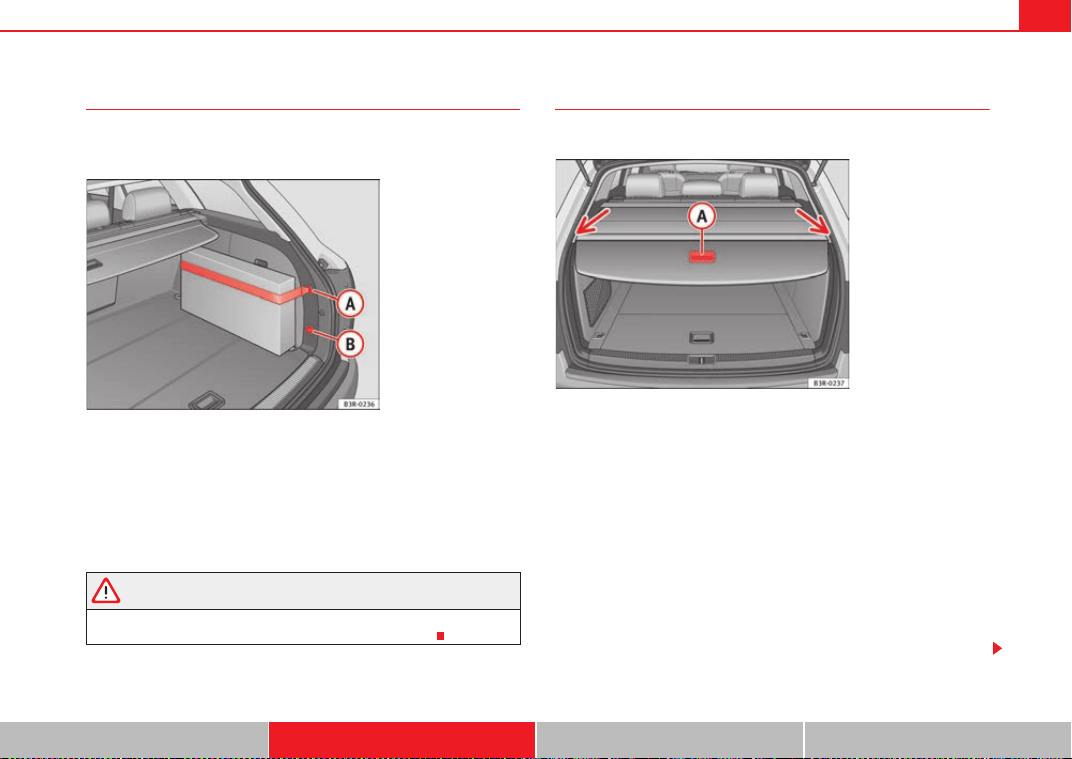
Seats and storage compartments 145
Safety First Operating Instructions Practical Tips Technical Specifications
Retaining strap*
The retaining strap can be used to secure items of luggage to
the right-hand side lining in the luggage compartment.
– Hook the retaining strap into housing or ⇒ fig. 119.
You can attach the strap to the top or bottom housing, depending on the size
of the object you wish to secure.
To secure shorter objects, the retaining strap can also be attached to the
centre. However, this is only possible if the strap is attached to housing .
WARNING
The retaining strap should only be used to hold objects weighing up to 5
kg. Heavier objects cannot be safely secured (risk of injury).
Luggage compartment cover*
The cover blocks the view into the luggage compartment.
Pulling out the luggage compartment cover
–Using handle ⇒ fig. 120, pull the rolled-up cover evenly
towards the rear of the vehicle.
– Insert the ends of the bar into the grooves in the left and right-
hand side trim ⇒ fig. 120 -arrows-.
Retracting the luggage compartment cover
– Lift the bar out of the grooves in the side trim.
– Let the cover roll up slowly.
Removing and installing the luggage compartment cover ⇒ page 147
Fig. 119 Retaining strap
attached to right-hand
side lining
A
A
A
B
A
B
Fig. 120 Tailgate open
with luggage compart-
ment cover closed
A
A
ExeoST_EN.book Seite 145 Freitag, 3. September 2010 11:41 11
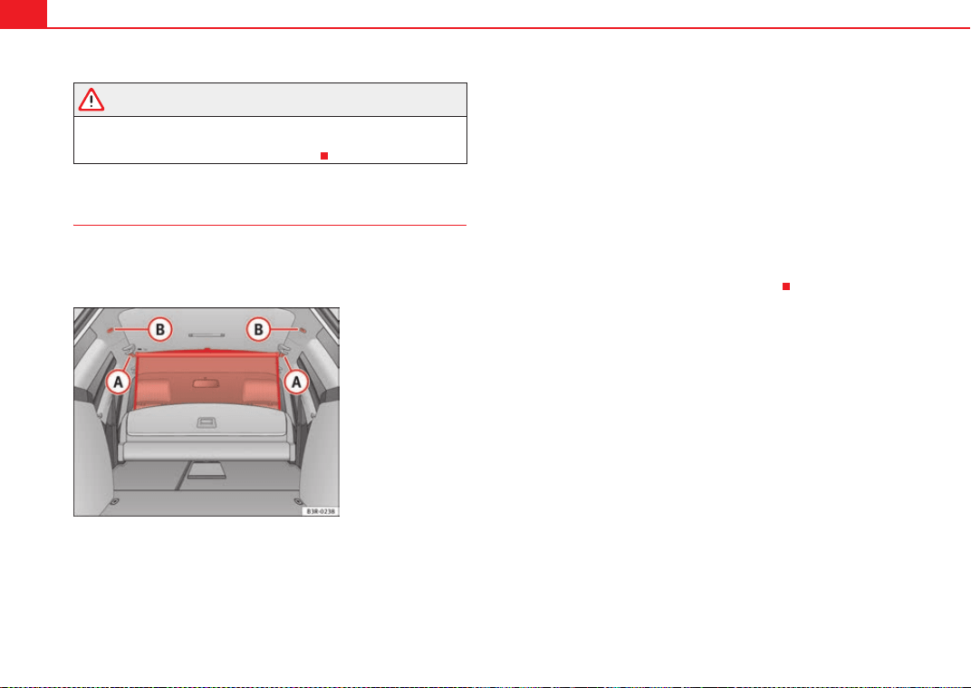
Seats and storage compartments146
WARNING
The luggage compartment cover should not be used as a storage shelf.
Articles placed on this cover could cause injury to vehicle occupants in an
accident or if the brakes are applied suddenly.
Net partition*
The net partition prevents loose objects in the luggage
compartment from being thrown forward into the passenger
compartment (e.g. under sudden braking).
Pulling out and securing the net partition
– Pull the net up as far as it will go.
– Engage the ends of the bar in the retainers ⇒ fig. 121.
Using the net partition with the rear backrest folded down
– Fold down the rear backrests ⇒ page 149.
– Pull the net upwards.
– Engage the ends of the bar in the retainers ⇒ fig. 121.
Retracting the net partition
– Unhook the bar from the retainers.
– Let the net retract slowly.
Removing and installing the net partition ⇒ page 147.
Fig. 121 Retainers for the
net partition
A
B
A
A
ExeoST_EN.book Seite 146 Freitag, 3. September 2010 11:41 11
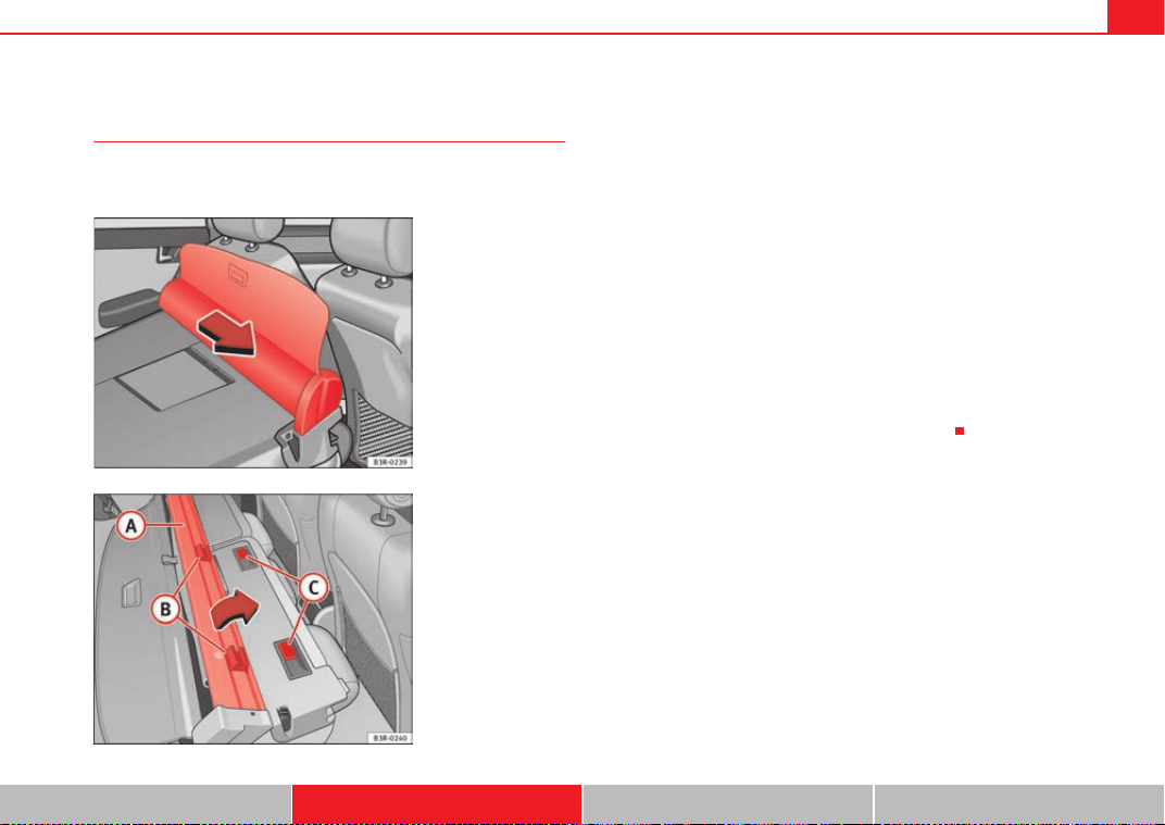
Seats and storage compartments 147
Safety First Operating Instructions Practical Tips Technical Specifications
Removing and installing luggage compartment cover / net
partition
The luggage compartment cover / net partition can only be
removed when the rear backrests are folded forwards.
Removing luggage compartment cover / net partition
– Open the right-hand rear door.
– Fold down the backrests ⇒ page 149.
– Pull the net partition in the direction indicated ⇒ fig. 122 and lift
it out of the retaining rails.
Installing luggage compartment cover / net partition
– Open the right-hand rear door.
– Fold down the backrests ⇒ page 149.
– Fit the net partition on the backrest so that the retainers
are located next to the retaining rails ⇒ fig. 123.
– Push the luggage compartment cover / net partition towards the
left-hand side of the vehicle as far as it will go.
Fig. 122 Removing
luggage compartment
cover / net partition
Fig. 123 Installing
luggage compartment
cover / net partition
A
A
A
B
A
C
ExeoST_EN.book Seite 147 Freitag, 3. September 2010 11:41 11
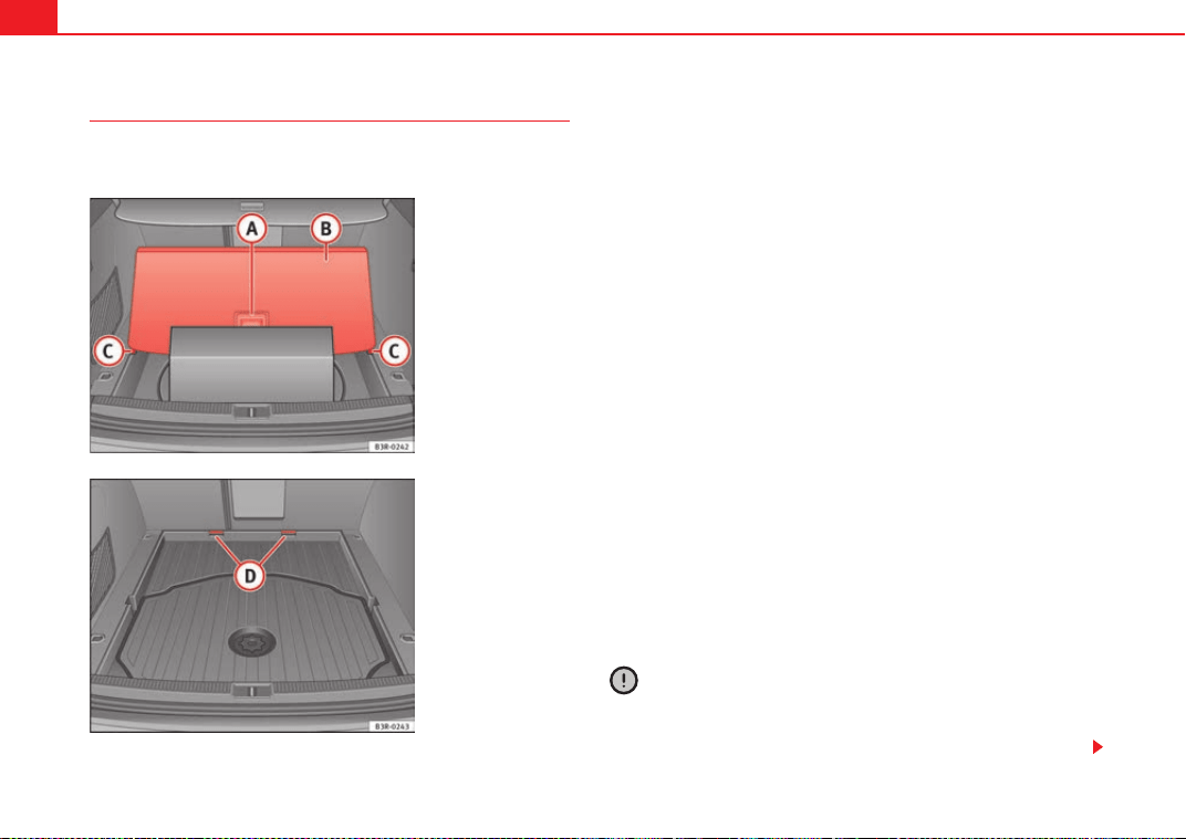
Seats and storage compartments148
Luggage compartment liner*
You can use the liner to protect the inside of the luggage
compartment when carrying wet or dirty items.
Lifting the floor panel
–Open the tailgate.
– Take hold of handle ⇒ fig. 124, lift the floor panel and line
up the bottom corners of the floor panel with the recesses .
– Put the items you are transporting onto the luggage compart-
ment liner
Folding the floor panel
–Open the tailgate.
– Take hold of the handle ⇒ fig. 124 and fold out the floor
panel as far as the rear backrest.
Removing the floor panel
–Open the tailgate.
– Take hold of the handle ⇒ fig. 124 and fold out the floor
panel as far as the rear backrest.
– Pull the complete floor panel towards the rear of the vehicle so it
comes out of the retainers ⇒ fig. 125.
Small items can also be stored under floor panel ⇒ fig. 124.
The space available for carrying items in the luggage compartment liner can
be increased by folding out the floor panel or removing it completely.
Caution
When the floor panel is folded out to the upright position you should not
transport items weighing more than 7.5 kg, or items which exceed 2/3 of the
height of the upright floor panel.
Fig. 124 Floor panel
raised
Fig. 125 Floor panel
removed for increased
luggage space
A
A
A
B
A
C
A
A
A
A
A
D
A
B
ExeoST_EN.book Seite 148 Freitag, 3. September 2010 11:41 11
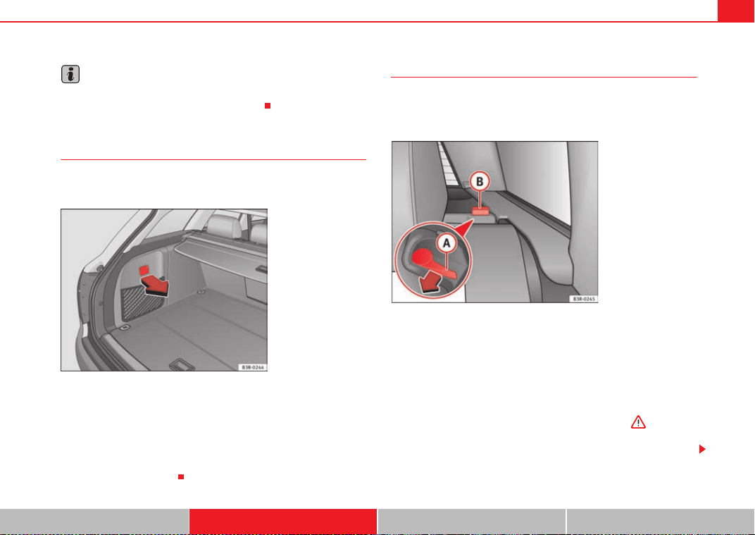
Seats and storage compartments 149
Safety First Operating Instructions Practical Tips Technical Specifications
Note
It is advisable to secure the items by means of a strap secured to the
fastening rings on the left and the right hand side.
Side storage compartment
The CD-ROM player for the navigation system* is located in
the left side compartment of the luggage compartment.
– To open the storage compartment, pull the handle
forwards⇒ fig. 126.
CD-ROM player for navigation system*
The CD-ROM player for the navigation system is located in this storage
compartment in the luggage compartment. Separate operating instructions
are enclosed for this system.
Extending the luggage compartment
The two sections of the backrest can be folded forwards either
together or separately to increase the capacity of the luggage
compartment.
Folding the backrest forwards
– Press the release lever ⇒ fig. 127 in the direction indicated
by the arrow.
–Fold down the backrest.
Returning the backrest to its upright position
– Push the backrest up until it engages securely ⇒ . The red
marking on the tab should no longer be visible when the
backrest is properly secured.
Fig. 126 Luggage
compartment: Side trim
with closed storage
compartment
Fig. 127 Backrest release
lever
A
A
A
B
ExeoST_EN.book Seite 149 Freitag, 3. September 2010 11:41 11

Seats and storage compartments150
WARNING
• Make sure that the rear backrest is securely locked in position so that
the seat belt can provide proper protection on the centre rear seat.
• The rear backrest must always be securely latched so that objects
stored in the luggage compartment will not fly forward during sudden
braking.
Caution
When returning the backrest to an upright position, make sure that the seat
belts for the outer rear seats are in their guides, so that they cannot be caught
up and damaged in the catches for the backrest.
Ski bag*
You can use the ski bag to transport skis or other extra-long
objects safely inside the vehicle without soiling or damaging
the upholstery.
Fig. 128 Detailed view of
the rear of the rear back-
rest: Ski bag cover
Fig. 129 Fastening the
ski bag in the seatbelt
buckle
ExeoST_EN.book Seite 150 Freitag, 3. September 2010 11:41 11
Seats and storage compartments 151
Safety First Operating Instructions Practical Tips Technical Specifications
Loading
–Open the tailgate.
– Press the release catch for the ski bag cover ⇒ page 150,
fig. 128 -arrow- and swivel the cover downwards.
– Pull down the centre rear armrest.
– From the passenger compartment, press down the release catch
for the ski bag cover and pull out the cover.
– Pull out and unfold the ski bag.
– The long items can now be loaded through the luggage compart-
ment into the ski bag ⇒ .
Securing
– Insert the fastening belt ⇒ page 150, fig. 129 of the ski bag
into the centre seat belt buckle .
– Pull the free end of belt to tighten.
Storing
– Close the cover of the load-through hatch in the luggage
compartment.
– Carefully fold away the ski bag.
– Close the inside cover of the load-through hatch from the
passenger compartment.
WARNING
The ski bag must be secured in place with the fastening belt after it has
been loaded.
Note
Do not fold away the ski bag after use if it is still damp.
Roof rack / roof rails*
Description
Additional luggage can be carried on the roof rack.
Note the following points if you intend to carry loads on the roof:
• We recommend using the cross bars from the of SEAT Genuine Accesso-
ries range.
• These cross bars form the basic elements of a complete roof rack system.
For safety reasons, however, the corresponding additional fastenings must
be fitted to carry luggage, bicycles, surfboards, skis and boats. All the
components of this system are available from Authorised Service Centres.
Caution
Any damage to the vehicle caused by the use of other types of roof rack or
incorrect installation will not be covered by the factory warranty. The roof rack
system must therefore be installed exactly according to the instructions
provided.
A
A
A
B
A
C
ExeoST_EN.book Seite 151 Freitag, 3. September 2010 11:41 11
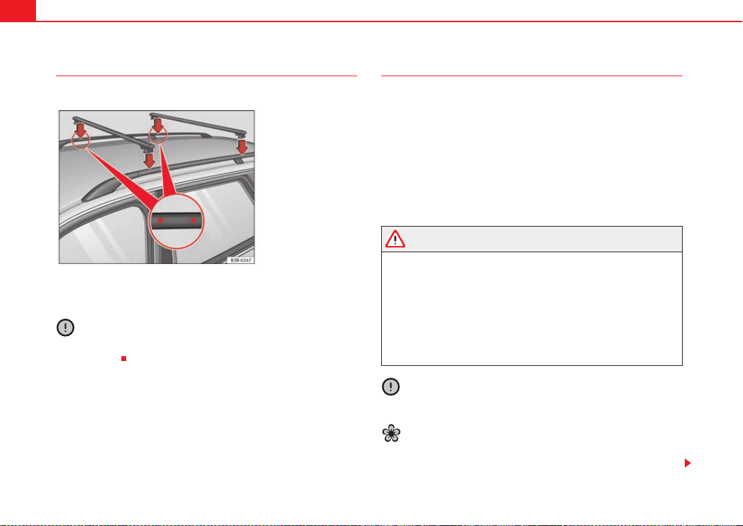
Seats and storage compartments152
Attachment points
The roof rack must be attached at the marked points only.
The cross-bars must be fitted exactly between the points marked on the roof
railings ⇒ fig. 130. The markings are visible on the inside of the railings.
Caution
A roof rack unit must not be used if the vehicle is not equipped with roof rails
(basic support).
Roof load
Loads carried on the roof must be securely attached. The
vehicle's handling is affected whenever you carry loads on
the vehicle.
The authorised load on the roof of your vehicle is 75 kg. Use the weight of the
roof rack system and that of the load as a basis to calculate the roof load.
If less resistant systems are used, the roof rack must not be loaded to the
maximum weight permitted. If less resistant systems are used, these must
only be loaded to the maximum weight permitted indicated in the assembly
instructions.
WARNING
• Loads carried on the roof must be securely attached. Failure to do so
could result in an accident.
• Do not exceed the maximum roof load for the vehicle, the maximum
axle loads or the maximum gross vehicle weight. Failure to do so could
result in an accident.
• When transporting heavy or bulky loads on the roof, bear in mind that
the vehicle's handling is affected by the extra weight on the roof and a
possible susceptibility to cross winds. Adjust your speed and driving style
accordingly to avoid accidents.
Caution
Please take extra care not to let the tailgate strike the roof load when open.
For the sake of the environment
Roof racks are often left attached for convenience, even when they are not
being used. However, the increased air resistance means that the vehicle
Fig. 130 Attachment
points for cross bars
ExeoST_EN.book Seite 152 Freitag, 3. September 2010 11:41 11
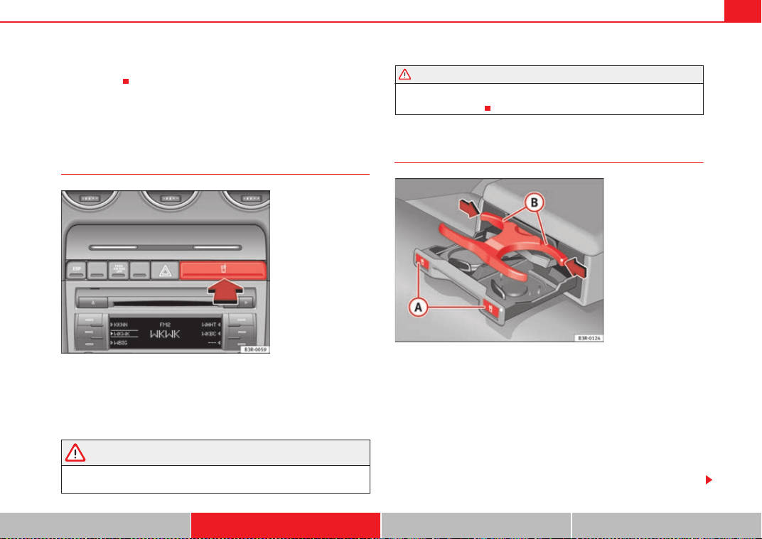
Seats and storage compartments 153
Safety First Operating Instructions Practical Tips Technical Specifications
uses more fuel. For this reason you should always take off the roof rack when
it is not in use.
Drink holder
Front drink holder
– To open the drink holder, press the symbol on the drink holder
lid ⇒ fig. 131
– To close the drink holder, press it in until it engages.
WARNING
• Do not put any hot drinks in the drink holder while the vehicle is
moving. You can be scalded if the hot liquid is spilt.
• Do not use hard china cups or glasses. These could cause injury in the
event of an accident.
Drink holder in the rear armrest*
Opening the drink holder
–Press the symbol
⇒ fig. 132.
Adjusting the retainer arm
– To adjust one of the retainer arms , release it by pressing in
the direction indicated (arrow) and move it as required.
The retainer arm should be positioned against the drink holder so that it is
held securely.
Fig. 131 Detailed view of
the dash panel: Drink
holder
WARNING (continued)
Fig. 132 Drink holder in
the rear armrest
A
A
A
B
ExeoST_EN.book Seite 153 Freitag, 3. September 2010 11:41 11
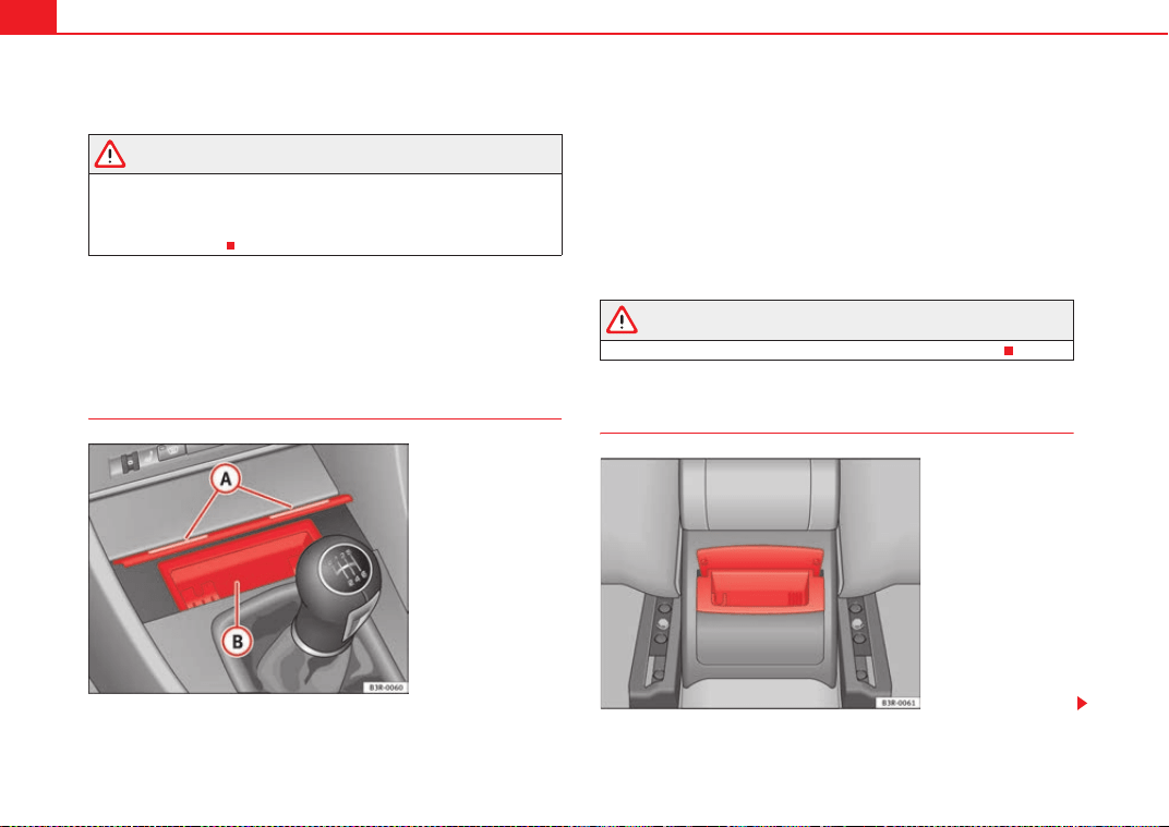
Seats and storage compartments154
One or two drink holders can be held in the centre console.
WARNING
• Do not put any hot drinks in the drink holder while the vehicle is
moving. You can be scalded if the hot liquid is spilt.
• Do not use hard china cups or glasses. These could cause injury in the
event of an accident.
Ashtray*, cigarette lighter* and electric
sockets*
Front ashtray*
Opening the ashtray
– Lightly press the front part of the ashtray ⇒ fig. 133.
Removing the ashtray
– Take hold of the sides of the ashtray ⇒ fig. 133 and lift it out.
Fitting the ashtray casing
– Insert the casing and press it into its mountings.
WARNING
Never put waste paper in the ashtray, as this could cause a fire.
Rear ashtray
Fig. 133 Centre console:
Open ashtray
A
A
A
B
Fig. 134 Rear ashtray
ExeoST_EN.book Seite 154 Freitag, 3. September 2010 11:41 11
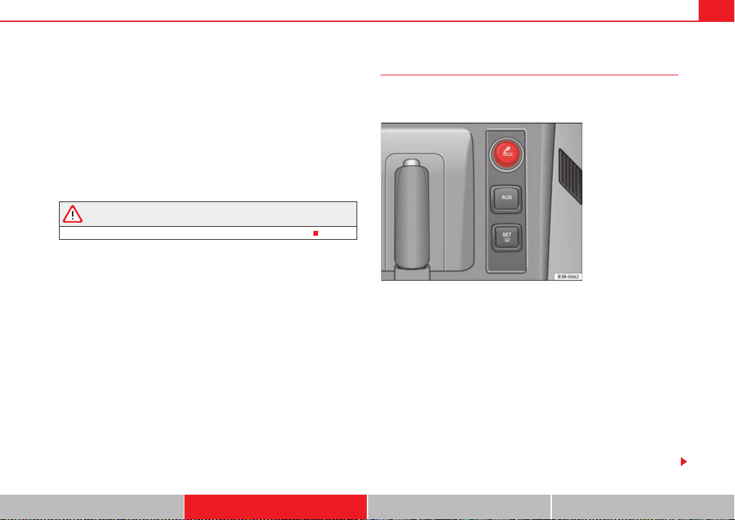
Seats and storage compartments 155
Safety First Operating Instructions Practical Tips Technical Specifications
Opening the ashtray
– Lift the lid.
Removing the ashtray
– Take hold of the lid ⇒ page 154, fig. 134 and lift out the ashtray.
Fitting the ashtray casing
– Open the lid on the ashtray and press the casing into the
mounting as far as it will go.
WARNING
Never put waste paper in the ashtray, as this could cause a fire.
Cigarette lighter*
The 12 volt socket for the cigarette lighter can also be used as
a power source for other electrical appliances.
Using the cigarette lighter
–Press in the cigarette lighter button.
– Wait for the lighter to pop out slightly.
– Pull out the cigarette lighter immediately.
– Use the glowing heater element of the cigarette lighter to light
your cigarette.
– Put the cigarette lighter back in its socket.
Operating the socket
– Take out the cigarette lighter.
Fig. 135 Cigarette lighter
in the centre console
ExeoST_EN.book Seite 155 Freitag, 3. September 2010 11:41 11
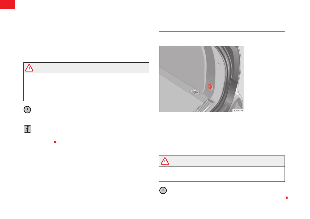
Seats and storage compartments156
– Insert the plug of the electrical appliance into the cigarette
lighter socket.
The cigarette lighter ⇒ fig. 135 employs a standard 12 volt socket, which can
also be used as a power source for electrical appliances. The appliances
connected to the socket must not exceed a power rating of 100 W.
WARNING
• Be careful when using the electric cigarette lighter. Carelessness or
negligence when using the cigarette lighter can cause burns.
• The lighter will only work when the ignition is switched on.
• The electrical sockets and, therefore, any appliances connected to
them will only work when the ignition is switched on.
Caution
Always use the correct type of plugs to avoid damaging the sockets.
Note
The use of electrical appliances with the engine switched off will cause a
battery discharge.
Electric socket in the luggage compartment*
Electrical equipment can be connected to the 12 volt socket.
– Lift the electrical socket cover ⇒ fig. 136.
– Insert the plug of the electrical appliance into the socket.
Electrical equipment can be connected to the 12 volt socket. The appliances
connected to the socket must not exceed a power rating of 100 W.
WARNING
The power points, and any accessories connected to them are also func-
tional with the ignition switched off or the key removed. To avoid the risk
of injury, never leave children unsupervised in the vehicle.
Caution
Always use the correct type of plugs to avoid damaging the sockets.
Fig. 136 Detailed view of
the side trim in the
luggage compartment: 12
volt socket
ExeoST_EN.book Seite 156 Freitag, 3. September 2010 11:41 11
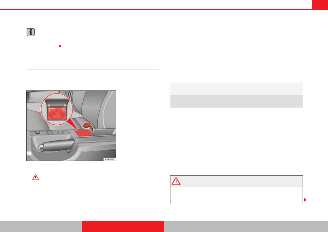
Seats and storage compartments 157
Safety First Operating Instructions Practical Tips Technical Specifications
Note
The use of electrical appliances with the engine switched off will cause a
battery discharge.
230 volt socket for Europlug*
Electrical equipment can also be connected to the 230 volt
socket in the centre console.
The 230 Volt socket can only be used when the engine is running
⇒ .
In vehicles with folding cover:
– Hold the cover of the socket at the lower recess.
– Lift the cover to open ⇒ fig. 137.
Inserting the Europlug
– Insert the Europlug in the socket. The childproof safety device on
the socket is deactivated.
– If necessary, press the Europlug as far as possible into the socket
to ensure it is correctly inserted and will not jump out of place
while driving over a bump or similar.
LED warning lamp above socket
Equipment which may be connected
The 230 volt socket can be used to connect electrical equipment with a Euro-
plug. Please note that the power consumption in this socket must not exceed
150 watts (peaks of 300 watts).
Even when more than one appliance is connected, the total consumption of
all the appliances must not exceed 150 watts. If necessary, please refer to the
manufacturer's label to confirm the power consumption of the connected
equipment.
All connected appliances should be in perfect working order without any
faults.
WARNING
• Heavy appliances or connectors (for example, adapters) which hang
down directly from the Europlug socket may damage the socket with the
resultant risk of injury.
Fig. 137 Centre console:
230 volt socket
Steady green
light:
The childproof safety device is disconnected. The socket
is ready for use
Flashing red
light:
There is a fault, for example, disconnection due to
excess current or temperature
ExeoST_EN.book Seite 157 Freitag, 3. September 2010 11:41 11
Seats and storage compartments158
• Ensure that appliances connected to the socket are secure to prevent
them from being thrown around the vehicle in the event of sharp braking or
an accident. This could result in severe injury or loss of life ⇒ page 16,
“Storing objects”.
• Never spill liquid over the socket – there is a risk of death. If any mois-
ture enters the socket, ensure that it is thoroughly dry before using.
• Improper use of the sockets or electrical accessories can lead to serious
injuries or cause a fire, with the resultant risk of injury.
• Children must never be left alone in the vehicle with the engine
running. They could cause an accident.
• Appliances connected to the socket do not behave in the same way as
when they are connected to the mains power supply. They may overheat
during use and cause injury.
• When using adapters and extension leads, the childproof safety device
on the 230 volt socket is disconnected and the socket is live. Risk of injury!.
• Never insert objects which conduct electricity, such as a needle, in the
pins of the 230 volt socket. There is a risk of death.
• Always switch off electrical appliances connected to the socket if the
inverter goes off as a result of overheating. Failure to comply could result
in injuries.
Caution
• The instructions for handling appliances connected to the socket must be
observed.
• If the power consumption of the appliances connected exceeds 150
watts, the socket inverter will overheat. If the temperature exceeds a certain
value, the inverter will switch off. It may also switch off if the outside temper-
ature is very high, even if the power consumption is normal. The inverter will
switch on again automatically after it has cooled down. Appliances
connected to the socket, and which have been left switched on, will automat-
ically come back on ⇒ .
• Do not connect neon lamps to the socket. For technical reasons, these
could break down.
• Do not connect 115 volt appliances to the 230 volt power socket, as they
could be damaged. If you have any queries, please check the manufacturer's
label for details of the power supply accepted by the appliance.
• With some adapters, for example for laptops, their built-in overload
disconnection system prevents the equipment from switching on in the event
of an excessive start-up current. In this case, disconnect the adapter from the
power supply and try to reconnect after ten seconds.
Note
• Non-insulated equipment may cause interference to the radio or vehicle
electronics.
• The Europlug socket has a built-in childproof device and only carries live
current when the Europlug is correctly plugged in.
• Some appliances may not operate correctly in the absence of adequate
power (watts).
• In some countries this socket is 115 volts. Therefore the socket should
have a different inverter installed at the factory. You can obtain retrofit kits
from your Authorised Technical Service. Do not connect 115 Volt appliances
to the 230 Volt socket.
• The use of electrical equipment in the vicinity of the aerial in the rear
window may cause interference to the reception of stations broadcasting in
AM.
WARNING (continued)
ExeoST_EN.book Seite 158 Freitag, 3. September 2010 11:41 11
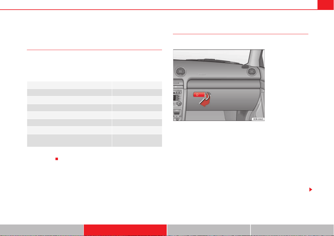
Seats and storage compartments 159
Safety First Operating Instructions Practical Tips Technical Specifications
Compartments
Overview
There are several storage compartments at various points in
the vehicle.
Your vehicle has the following storage compartments:
Some of the compartments listed are only provided in certain models or are
optional extras.
Glove compartment
The lockable glove compartment is equipped with a light.
Opening the glove compartment
– Pull the handle on the lid in the direction indicated (arrow)
⇒ fig. 138 and open the lid.
Closing the glove compartment
– Close the lid and push it in until it engages.
If the side lights or headlights are switched on, the light in the glove compart-
ment comes on when it is opened.
The lid has separate holders for a pen and a note pad.
First-aid kit*
Emergency triangle*
Glove compartment ⇒ page 159
Storage compartment in the centre console
On-board documentation compartment*
Compartments in the door trims ⇒ page 160
Coat hooks ⇒ page 160
Side storage compartment in luggage com-
partment
Fig. 138 Glove compart-
ment
ExeoST_EN.book Seite 159 Freitag, 3. September 2010 11:41 11
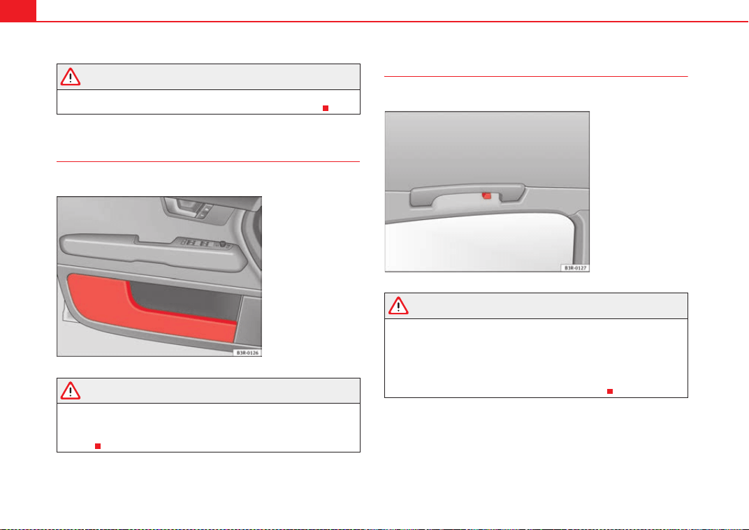
Seats and storage compartments160
WARNING
For safety reasons, the glove compartment must always be closed when
the vehicle is moving. Failure to do so could result in an accident.
Compartments in the door trim
Storage compartments are provided in the door trims.
WARNING
The storage compartments in the door trims should only be used to store
small objects. Make sure that they are stored safely inside the compart-
ment, as they might otherwise impair the protection offered by the side
airbags.
Coat hooks
There is a coat hook above each of the rear doors.
WARNING
• Please make sure that any items of clothing hanging from the coat
hooks do not obstruct your view to the rear.
• The coat hooks should only be used for lightweight clothing. Do not
leave any heavy or sharp objects in the pockets.
• Do not use clothes hangers to hang up the clothing, as this could inter-
fere with the function of the head-protection airbags*.
Fig. 139 Door trim with
storage compartment
Fig. 140 Area above the
rear doors: Coat hooks
ExeoST_EN.book Seite 160 Freitag, 3. September 2010 11:41 11
Seats and storage compartments 161
Safety First Operating Instructions Practical Tips Technical Specifications
Compartments in the front seats
There is a storage compartment with a lid at the front of each
front seat.
Opening
– Pull the handle to open the compartment.
Closing
– Close the lid and push it in until it engages.
Note
The compartments will hold a maximum weight of 1 kg.
ExeoST_EN.book Seite 161 Freitag, 3. September 2010 11:41 11
Air conditioning162
Air conditioning
2C-Climatronic
Description
The air conditioner is designed to automatically keep the
passenger compartment at the temperature you find most
comfortable at all times of the year.
Recommended settings:
– Set the temperature to 22 °C (71 °F).
–Press the button ⇒ page 164, fig. 141.
The following setting quickly provides a comfortable temperature inside the
vehicle. We therefore recommend you do not modify the setting unless you
find this temperature uncomfortable or where circumstances require as such.
The air conditioner provides heating and ventilation and also cools and dehu-
midifies the air inside the vehicle.
The air conditioner is fully automatic and will constantly maintain the temper-
ature which has been set. To achieve this, the temperature of the air supplied
to the interior, the blower speed (volume of air delivery) and the air distribu-
tion are regulated automatically. The system also takes solar radiation into
account and, therefore, no subsequent manual readjustments are required.
Therefore, automatic mode ⇒ page 165 should be used for the comfort of all
the passengers in virtually all conditions throughout the year.
Please note the following points:
The humidity of the air is automatically reduced when the system cools the
interior of the vehicle. This helps to prevent condensation on the windows.
If the humidity and temperature outside the vehicle are high, condensation
can drip off the evaporator in the air cooling system and form a pool under-
neath the vehicle. This is normal and does not indicate a leak.
If the outside temperature is low, the blower normally only switches to a
higher speed once the coolant has warmed up sufficiently (this does not
apply to the defrost setting).
In order to achieve maximum engine power, the air conditioner compressor is
temporarily switched off when pulling away from standstill with full throttle.
The compressor also switches off if the coolant temperature is excessively
high to ensure adequate engine cooling under extreme loads.
Pollution filter
The pollution filter (a combined particulate filter and activated charcoal filter)
serves as a barrier against impurities in the outside air, including dust and
pollen.
For the air conditioner to work with maximum efficiency, the pollution filter
element must be replaced at the intervals specified in the Service Plan.
If the vehicle is driven in areas with a high level of air pollution and the filter
is no longer fully effective, it may be necessary to change the filter element
more frequently.
Caution
• If you suspect that the air conditioner system is damaged, switch over to
ECON mode to prevent further damage and have the system checked by a
qualified workshop.
• Repairs to the air conditioner require specialist knowledge and special
tools. For this reason, please contact a qualified workshop if the system is not
working properly.
AUTO
ExeoST_EN.book Seite 162 Freitag, 3. September 2010 11:41 11
Air conditioning 163
Safety First Operating Instructions Practical Tips Technical Specifications
Note
• Keep the air intake slots in front of the windscreen clear of snow, ice and
leaves to ensure unimpaired heating and cooling and to prevent the windows
misting over.
• The air from the outlets flows through the passenger compartment and
out through the slots below the rear window. Therefore, do not cover these
slots with items of clothing or other objects.
• The air conditioner operates most effectively with the windows and the
sliding/tilting sunroof* closed. However, if the vehicle has heated up after
standing in the sun for some time, the air inside can be cooled more quickly
by opening the windows briefly.
ExeoST_EN.book Seite 163 Freitag, 3. September 2010 11:41 11
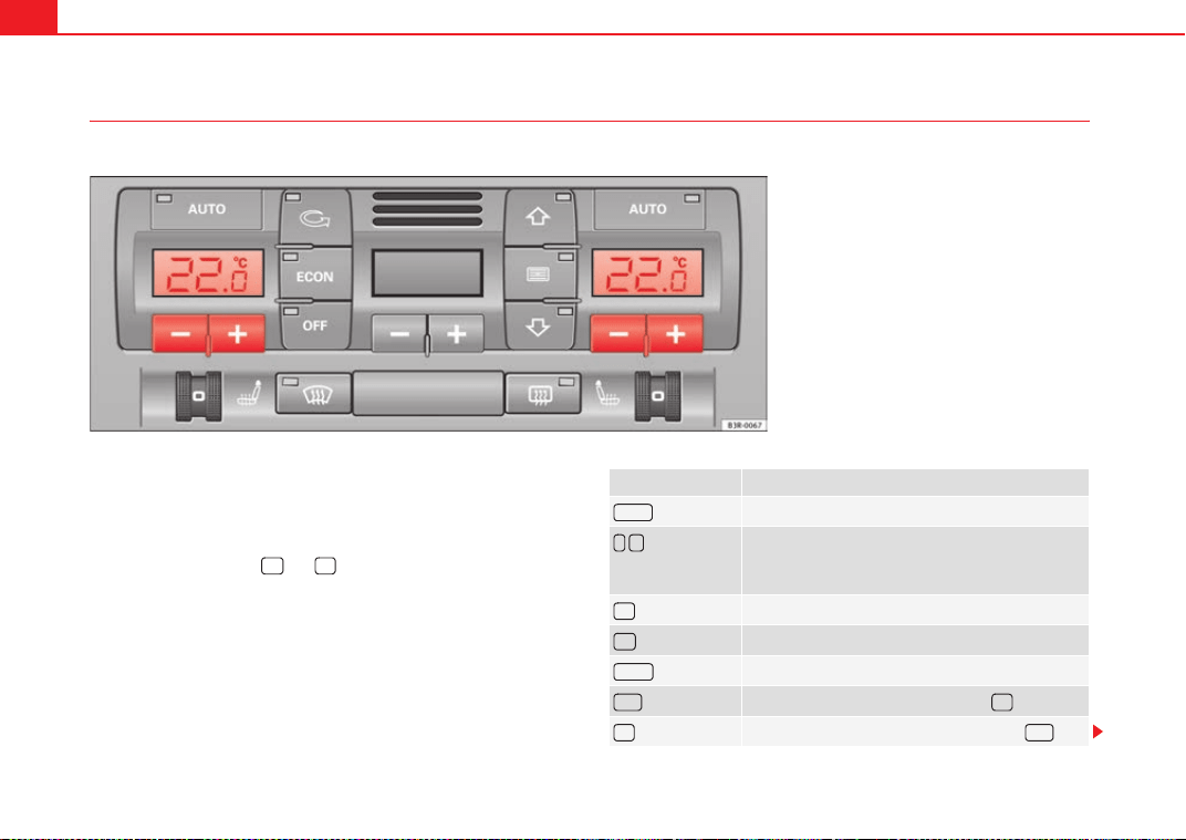
Air conditioning164
Controls
This overview will help you become quickly familiar with the controls for the air conditioner.
The left-hand display shows the temperature selected for the left-hand side
and the right-hand display the temperature for the right-hand side.
The functions can be switched on or off by briefly pressing the buttons. The
diode on the buttons lights up when the function is enabled.
The grille between buttons and must be kept clear, as the tempera-
ture sensors are located behind the grille.
• Do not cover the grille.
• Do not clean the grille with a vacuum cleaner, as this could damage the
temperature sensors located behind the grille.
Fig. 141 Air conditioner controls
Button(s) Meaning
Automatic mode
(left and right
sides)
Temperature selection for the driver
and front passenger sides
Defrost
Manual air recirculation mode
Switches off air cooling
Switches off air conditioner (instead of )
Automatic air recirculation mode (instead of )
AUTO
- +
<
ECON
OFF
OFF
ExeoST_EN.book Seite 164 Freitag, 3. September 2010 11:41 11
Air conditioning 165
Safety First Operating Instructions Practical Tips Technical Specifications
The , and buttons (which regulate air distribution) can either be
selected individually or in combination.
Automatic mode
Standard setting for all seasons.
Switching on automatic mode
– Select a temperature between +18 °C (64 °F) and +29 °C (86 °F).
– Press the button ⇒ page 164, fig. 141.
The automatic mode maintains a constant temperature inside the vehicle and
dehumidifies the air. Air temperature, air delivery and air distribution are
regulated automatically to reach the desired interior temperature as quickly
as possible, and then to maintain this temperature. The system automatically
compensates for any variations in the outside temperature and for the effect
of direct sunlight.
The automatic temperature regulation only operates at temperature settings
between +18 °C and +29 °C. If a temperature below +18 °C is selected, LO
appears on the display. If a temperature is selected which is higher than
+29 °C, the display will show HI. In the maximum and minimum settings, the
climate control operates continuously with maximum cooling or heating
output and the temperature is not regulated automatically. The temperature
is not regulated.
Note
By keeping the button on the driver side pressed for several seconds,
the temperature of the passenger side can be set to the temperature of the
driver side or vice versa. The display indicates the new temperature value.
Selecting the temperature
Separate temperatures can be selected for the driver and
front passenger sides.
– Press the or buttons below the displays ⇒ page 164,
fig. 141 until the desired temperature is selected for the driver
side or front passenger side.
The currently selected temperature setting is shown in the display above the
buttons.
By keeping the button on the driver side pressed for several seconds,
the temperature of the passenger side can be set to the temperature of the
driver side or vice versa. The display indicates the new temperature value. The
previous temperature setting can be restored by resetting the display on the
driver or passenger side as required.
(centre buttons)
Adjusts blower speed
Air to the windows
Air from the dashboard outlets
Air to the footwells
Button(s) Meaning
- +
AUTO
AUTO
AUTO
- +
- +
AUTO
ExeoST_EN.book Seite 165 Freitag, 3. September 2010 11:41 11
Air conditioning166
Defrosting
The windscreen and side windows are defrosted or demisted
as quickly as possible.
– To enable this mode, press the ⇒ page 164, fig. 141 button.
– To disable, press the button again or select the button.
The temperature is regulated automatically. The air output is increased to
maximum and most of the air comes out of outlets 1 and 2 ⇒ page 169.
The air recirculation and ECON modes are switched off when the button is
pressed.
Air recirculation: manual activation
The air recirculation setting prevents fumes etc. from entering
the interior.
Activating air recirculation mode
–Press button ⇒ page 164, fig. 141 ⇒ .
Deactivating air recirculation mode
– Press the button again or
– Press the button or
–Press button .
In this setting, the air in the vehicle is constantly recirculated. We recommend
using the air recirculation mode in the following circumstances:
• When driving through a tunnel or in traffic congestions, to prevent
exhaust gas entering the interior of the vehicle.
WARNING
Do not drive for too long with the air recirculation mode enabled because,
if the compressor is disconnected, the windscreen may mist up because no
fresh air is entering the interior of the vehicle, with the subsequent risk of
accidents.
ECON Mode (economy)
ECON mode helps save fuel.
– To activate, press the button ⇒ page 164, fig. 141.
– To deactivate, press the button again or select the
button.
Air cooling is disconnected in ECON mode. The heating and the blower are
adjusted automatically. “ECON” stands for “Economy”. Disconnecting air
cooling (compressor) reduces fuel consumption.
Please note that the interior temperature must not be lower than the outside
temperature in ECON mode. The blower does not cool or dehumidify the air in
the interior. The windows could therefore mist up.
In diesel vehicles, the auxiliary heater is switched off in ECON mode to save
fuel.
Note
If the diode on the ECON button continues to light up when the ECON mode
has been switched off (i.e. the air conditioner has been switched on) this is
<
<
< AUTO
<
AUTO
<
ECON
ECON
ECON AUTO
ExeoST_EN.book Seite 166 Freitag, 3. September 2010 11:41 11
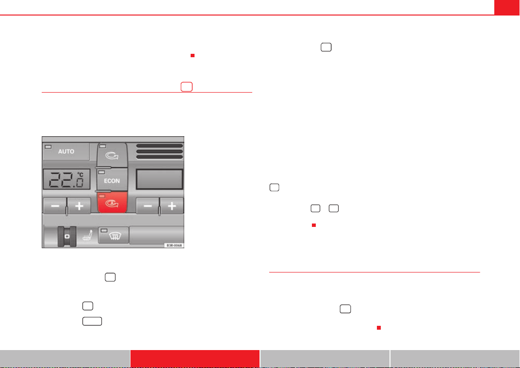
Air conditioning 167
Safety First Operating Instructions Practical Tips Technical Specifications
due to a defect in one of the air conditioner components. If a malfunction
should occur, please contact a specialised workshop.
Air recirculation: automatic activation*
If the outside air is polluted by diesel and petrol emissions,
an air quality sensor in the vehicle will automatically switch
on the air recirculation.
Activating air recirculation mode
– Press the button ⇒ fig. 142.
Deactivating air recirculation mode
– Press the button again or
– Press the button or
– Press button .
The automatic air recirculation mode should normally be left switched on at
all times.
The system is ready to operate approx. 30 seconds after the engine ignition
key has been turned. During this initial period, fresh air is fed into the vehicle.
If the air purity sensor in the air conditioner detects a certain concentration
of fumes in the outside air, the control unit will either pass the incoming air
through the pollution filter or automatically switch on the air recirculation. If
there is a high concentration of pollution in the outside air, the air conditioner
automatically switches to air recirculation and the supply of air from the
outside is cut off. As soon as the level of pollution decreases, air is fed into
the vehicle from the outside again.
The automatic air recirculation operates for a maximum period of 12 minutes.
If the windows mist up when the automatic air recirculation is on, press the
button immediately.
The automatic air recirculation switches itself off under certain circumstances
(for instance if or is selected). In “ECON” and at temperatures lower
than approx. 8 °C below zero, the automatic air recirculation mode is limited
to 12 seconds.
Switching the temperature display from °C to °F and vice
versa
The temperature display can be switched from °C (degrees
Celsius) to °F (degrees Fahrenheit) and vice versa.
– Press and hold the button for air recirculation mode and
briefly press the plus button of the left-hand temperature
selector ⇒ page 164, fig. 141.
Fig. 142 Button for auto-
matic air recirculation
AUTO
<
<
<
ExeoST_EN.book Seite 167 Freitag, 3. September 2010 11:41 11
Air conditioning168
Switching the air conditioner on/off
Switching the air conditioner off: models with an button
– Press the button. The air conditioner is switched off and the
supply of air from outside the vehicle is cut off.
Switching the air conditioner off: models with a button
– Keep pressing the button for the blower until the display
segment is empty. The air conditioner is switched off and the
supply of air from outside the vehicle is cut off.
Switching the air conditioner on: models with an button
– Press the button again, or
– Press the button or
– Press one of the air distribution buttons , or .
Switching the air conditioner on: models with a button
– Press the button for the blower, or
– Press the button or
– Press one of the air distribution buttons , or .
The air conditioner also starts to operate if one of the blower or temperature
selector buttons is pressed.
Blower speed
The automatically selected blower speed can be reduced or
increased manually.
– Press the and buttons in the centre of the control panel
⇒ page 164, fig. 141 to set the blower to the desired speed (and
regulate the volume of air delivery).
The air conditioner system automatically regulates the blower speed
according to the interior temperature. However, you can also adjust the air
delivery manually. The current blower setting is illustrated by a bar in the
middle display (above the buttons).
Automatic change of passenger temperature
In order to automatically set the passenger temperature like the driver
temperature, press the button on the driver side for 2 seconds approx-
imately. In order to automatically set the driver temperature like the
passenger temperature, press the button on the passenger side for 2
seconds approximately.
OFF
OFF
-
OFF
OFF
AUTO
+
AUTO
- +
- +
AUTO
AUTO
ExeoST_EN.book Seite 168 Freitag, 3. September 2010 11:41 11
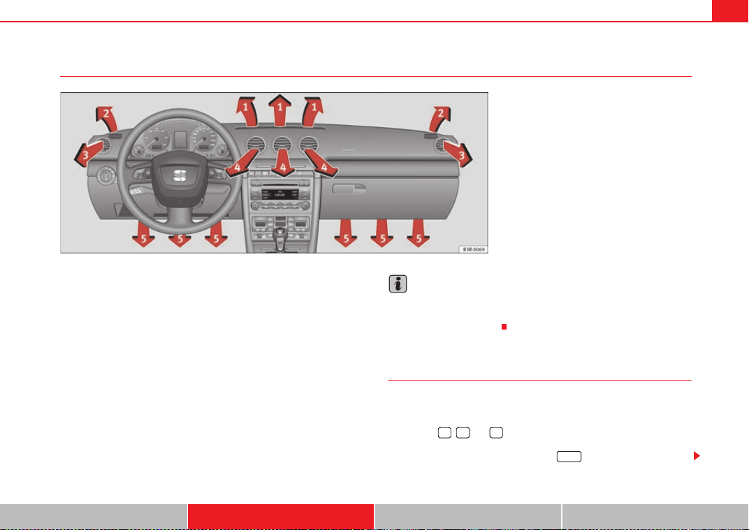
Air conditioning 169
Safety First Operating Instructions Practical Tips Technical Specifications
Air outlets
The air outlets ⇒ fig. 143 and can be operated as follows:
Outlets and
– The outlets can be opened and closed by turning the left thum-
bwheels.
– The direction of air delivery from the outlets can be varied as
required using the adjuster in the centre of each outlet grille. The
direction of air flow can be adjusted horizontally and vertically as
desired.
The flow of air from the outlets is controlled either automatically or manually,
depending on the operating mode selected. All the outlets can provide air
that is either heated, unheated or cooled.
The heater outlets for the rear footwells are located under the front seats.
They are controlled together with outlets .
Note
The cool air provided by the air conditioner is mainly issued from outlets
and . To ensure adequate cooling, outlets and should therefore
never be closed completely.
Air distribution
The automatically-programmed air distribution can be
altered manually.
The buttons , and can be operated either separately or in combi-
nation. To return to automatically controlled air distribution, switch off the
selected functions separately or press the button
Fig. 143 Dash panel: Location of air outlets
A
3
A
4
A
3
A
4
A
5
A
3
A
4
A
3
A
4
AUTO
ExeoST_EN.book Seite 169 Freitag, 3. September 2010 11:41 11
Air conditioning170
Each of the three buttons has a specific function. The numbers relate to the
air outlets ⇒ page 169, fig. 143.
Air directed to windows
This setting directs all the air to outlets 1 and 2. Unlike in setting , the
volume of air delivery remains the same.
Air to the driver/front passenger
All the air comes from outlets 3 and 4 in the dash panel and from the rear of
the centre console.
Air to the footwells
Most of the air emerges from outlets 5 and the outlets under the front seats.
Some of the air will also be issued from outlets 3 and 4.
Note
In all of the above air distribution settings, a small amount of air will still
come from the other outlets.
Economical use of the air conditioner
Economical use of the air conditioner will help save fuel.
Engine power is reduced and fuel consumption increases when the
air conditioner is in cooling mode. To ensure that the system is only
switched on when it is really necessary, please note the following
points:
– Select ECON mode if you wish to save fuel.
– Select ECON mode if you decide to open the windows or sunroof*
while driving.
– If the vehicle has heated up after standing in the sun, open the
windows and doors for a short time to cool the vehicle.
For the sake of the environment
By saving fuel you also reduce the amount of pollutants emitted from your
vehicle.
Key settings
When the ignition is switched on, the air conditioner settings
assigned to the key are selected automatically.
The air conditioner settings selected are automatically stored and assigned
to the key in use. When the vehicle is started, the air conditioner automati-
cally selects the settings assigned to the key. Hence, every driver automati-
cally obtains his/her preferred settings without having to select them manu-
ally.
Note
Should another driver use the key and enter other settings, the previous
settings will be deleted.
<
ExeoST_EN.book Seite 170 Freitag, 3. September 2010 11:41 11
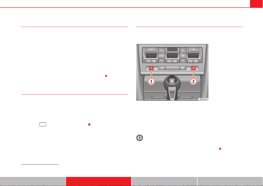
Air conditioning 171
Safety First Operating Instructions Practical Tips Technical Specifications
Solar-powered blower/sunroof*
If the vehicle is parked in sufficiently strong sunlight, the
blower will operate in solar-powered mode when the ignition
is switched off.
After the ignition is switched off, the blower is supplied with electrical power
from the sunroof. Please ensure that outlets 3 and 4 are open ⇒ page 169,
fig. 143 to ensure the best possible ventilation.
The blower only works when the sunroof is closed or tilted open at the rear.
If the air recirculation mode is on when you switch off the engine, the air
conditioner will automatically switch to fresh air ventilation.
Auxiliary heater*
Diesel vehicles are fitted with an auxiliary heater
2)
to raise the temperature of
the interior as quickly as possible. At outdoor temperatures below +5 °C and
with the engine running, the auxiliary heater will switch on and off automati-
cally depending on the temperature of the coolant.
In order to save fuel, the auxiliary heater can be can be switched off by briefly
pressing the button on the air conditioner.
Seat heating*
The surface and backrest of the front seats can be electrically
heated.
Turn thumbwheel or ⇒ fig. 144 to switch on and adjust the
heating on the left or right front seats.
The heating is switched off when the thumbwheel is set to 0. The temperature
settings range from 1 to 6.
Caution
To avoid damaging the heating elements of the seat heating, please do not
kneel on the seat or apply sharp pressure to a single point.
2)
For Nordic countries only.
%#/.
Fig. 144 Detailed view of
the dash panel: Thum-
bwheel controls for seat
heating
A
1
A
2
ExeoST_EN.book Seite 171 Freitag, 3. September 2010 11:41 11
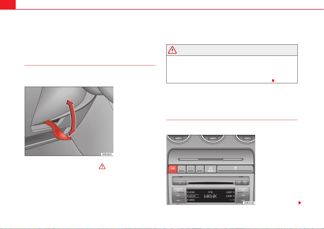
Driving172
Driving
Steering
Adjusting the steering wheel position
The height and reach of the steering wheel can be freely
adjusted to suit the driver
–Push the lever ⇒ fig. 145 down ⇒ .
– Move the steering wheel to the desired position.
– Then push the lever back up against the steering column until it
engages in position.
WARNING
• Never adjust the position of the steering wheel when the vehicle is
moving, as this could cause an accident.
• For safety reasons, the lever must always be securely engaged when
the vehicle is moving, so that the position of the steering wheel cannot
shift unexpectedly. Otherwise this could cause an accident.
Safety
Electronic Stability Programme (ESP)
ESP helps make driving safer in certain situations.
Fig. 145 Lever beneath
steering column
Fig. 146 Detailed view of
the centre console: ESP
button
ExeoST_EN.book Seite 172 Freitag, 3. September 2010 11:41 11
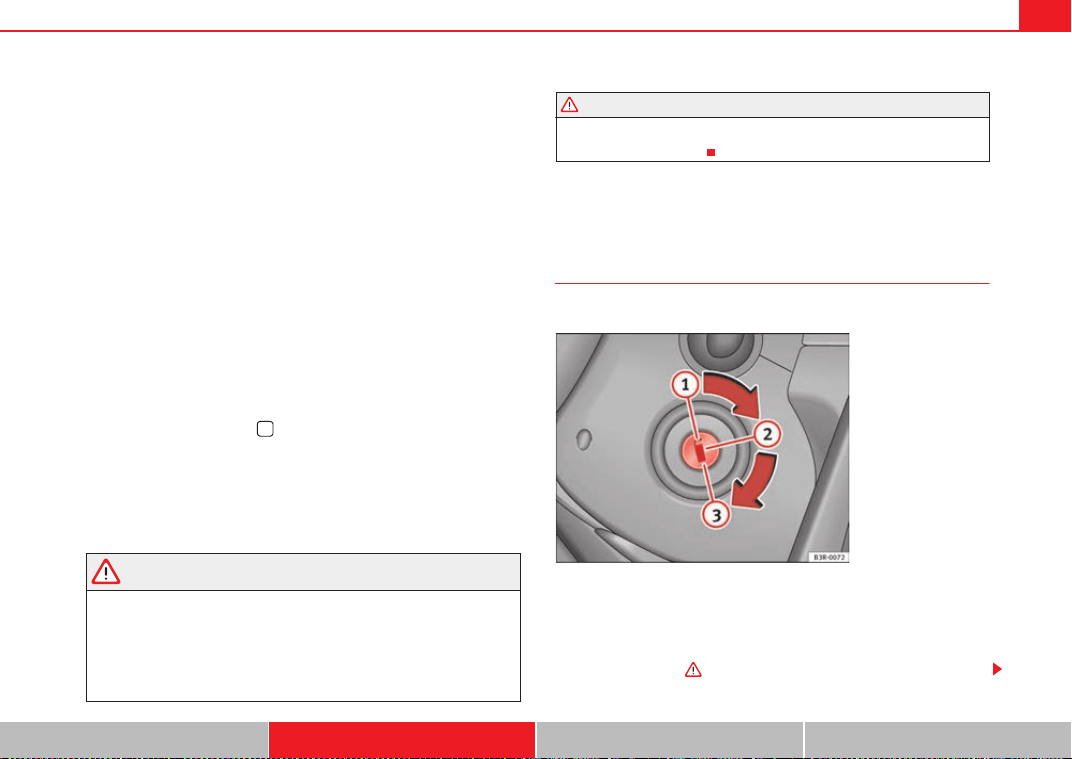
Driving 173
Safety First Operating Instructions Practical Tips Technical Specifications
The Electronic Stability Programme (ESP) contains the electronic differential
lock (EDL) and the traction control system (TCS). The ESP function works
together with the ABS. If a fault in the ABS occurs, both warning lamps light
up, but if the ESP fails, only the ESP warning lamp lights up.
The ESP is started automatically when the engine is started.
The ESP switch deactivates both TCS and ESP functions. The ESP, in spite of
being deactivated, will always self-connect when necessary if brakes are
being used.
The TCS can be deactivated when in cases where wheel sliding is desirable.
For example:
• When driving with snow chains,
• when driving in deep snow or on loose surfaces,
• when rocking the vehicle backwards and forwards to free it from mud, for
example.
Next, the button should be pressed to reactivate the TCS.
When does the warning lamp switch on or flash?
• On switching the ignition on, it lights up for about two seconds to carry
out a function control.
• The warning lamp will start flashing when the vehicle is moving if the ESP
or the TCS is activated.
• It will light up continuously if there is a malfunction in the ESP.
WARNING
• The Electronic Stability Programme (ESP) cannot defy the laws of
physics. This should be kept in mind, particularly on slippery and wet
roads and when towing a trailer.
• Always adapt your driving style to suit the condition of the roads and
the traffic situation. Do not let the extra safety afforded by ESP tempt you
into taking any risks when driving, as this can cause accidents.
• Please refer to the corresponding warning notes on ESP in ⇒ page 191,
“Intelligent technology”.
Ignition lock
Ignition key positions
The ignition key is used to start and stop the engine.
Position
The ignition key is inserted in this position. To engage the steering wheel
lock, take out the key and turn the wheel until you hear the pin engage. You
should always engage the steering lock when you leave the vehicle. This will
help to deter thefts ⇒ .
WARNING (continued)
Fig. 147 Ignition key
positions
A
1
ExeoST_EN.book Seite 173 Freitag, 3. September 2010 11:41 11
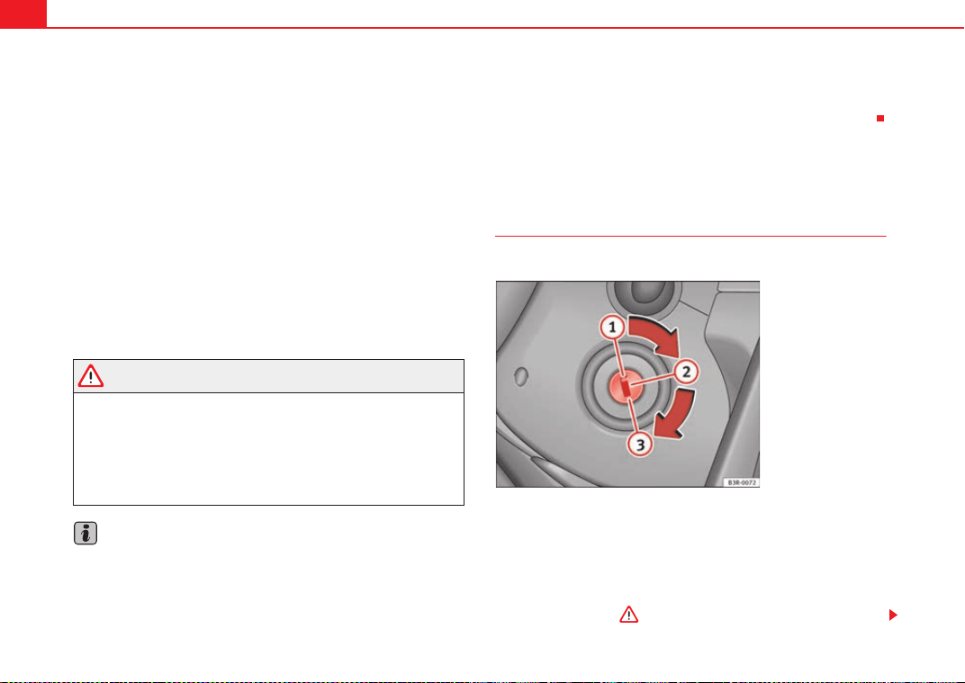
Driving174
Switching on the ignition/pre-heating glow plugs
If the key is difficult to turn in the lock, move the steering wheel (to take the
load off the steering lock mechanism) until the key turns freely. In the case of
vehicles with a diesel engine, the key is turned to this position to preheat the
glow plugs.
Starting the engine
The engine is started in this position. Electrical components with a high
power consumption are switched off temporarily.
After the engine has started, the ignition key returns to position by itself.
The ignition key has to be turned back to position before re-starting the
engine. The starter inhibitor in the ignition lock prevents the starter motor
from engaging when the engine is running, as this could cause damage.
Switching off the ignition
Turn the ignition key to this position.
WARNING
• Never remove the ignition key until the vehicle is stationary! Otherwise
the steering lock could engage suddenly, which could cause an accident.
• Always take the key with you when leaving the vehicle, even if you only
intend to be gone for a short time. This is particularly important if there are
children in the vehicle, as they might otherwise be able to start the engine
or use power-operated equipment (e.g. the electric windows), which could
cause injuries.
Note
• If the battery has been disconnected and then reconnected, it will be
necessary to leave the key in position for about 5 seconds before starting
the engine.
• Vehicles with automatic gearbox: After switching off the ignition, you can
only remove the ignition key if the selector lever is in position “P” (parking
lock). The selector lever is locked after the ignition key has been removed.
Starting and stopping the engine
Starting the engine
The engine can only be started with an original SEAT key.
Vehicles with a petrol engine:
– Use the foot brake.
– Manual gearbox: Push the clutch pedal all the way down.
– Move the gear lever into neutral (automatic gearbox: selector
lever to P or N) ⇒ .
A
2
A
3
A
2
A
1
A
1
A
2
Fig. 148 Ignition key
positions
ExeoST_EN.book Seite 174 Freitag, 3. September 2010 11:41 11
Driving 175
Safety First Operating Instructions Practical Tips Technical Specifications
– Turn the ignition key to position without pressing the acceler-
ator.
– Release the ignition key as soon as the engine starts (the starter
motor must not be allowed to run on with the engine).
Vehicles with a diesel engine:
– Use the foot brake.
– Manual gearbox: Push the clutch pedal all the way down.
– Move the gear lever into neutral (automatic gearbox: selector
lever to P or N) ⇒ .
– Turn the ignition key to position . The pre-heating indicator
light
D comes on while the glow plugs are preheating.
– When the indicator light
D goes out, turn the ignition key to
position . Do not press the accelerator.
– Release the ignition key as soon as the engine starts (the starter
motor must not be allowed to run on with the engine).
When starting a very cold engine, it may be a little noisy for the first few
seconds until oil pressure has built up in the hydraulic valve compensators.
This is quite normal, and no cause for concern.
If the engine fails to start straight away, stop after 10 seconds and try again
after about half a minute.
Glow plug system*
To assist starting at low temperatures, diesel engines are equipped with a
glow plug preheating system. The preheating time depends on the coolant
temperature and the outside temperature. Start the engine as soon as the
glow plug indicator light
D goes out.
When the engine is warm or at outside temperatures above +8 °C, the glow
plug indicator light will only come on for about one second. This means that
the engine can be started immediately.
If the engine will not start...
• ⇒ page 291
• ⇒ page 294
• ⇒ page 225, “Refuelling”
WARNING
Never run the engine in confined spaces, as the exhaust gases are
poisonous.
Caution
Avoid high engine speeds, full throttle and extreme load conditions until the
engine has reached its normal operating temperature, otherwise this can
damage the engine.
For the sake of the environment
Do not warm up the engine by running the engine with the vehicle stationary.
Start immediately. This will help avoid unnecessary exhaust emissions.
Stopping the engine
– Turn the ignition key to position ⇒ page 174, fig. 148.
WARNING
• Never switch the engine off until the vehicle is stationary.
A
3
A
2
A
3
A
1
ExeoST_EN.book Seite 175 Freitag, 3. September 2010 11:41 11
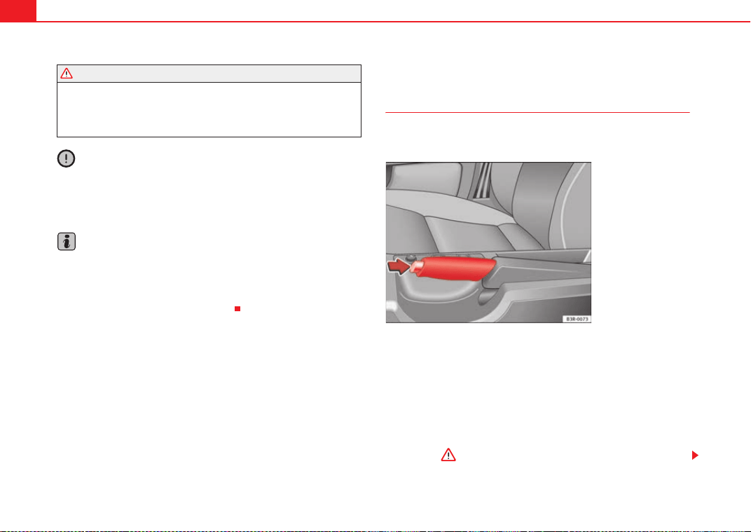
Driving176
• The brake servo and the power steering system work only when the
engine is running. You need more strength to steer and brake the vehicle
when the engine is switched off. Given that you will be unable to steer and
brake as usual, this could lead to a risk of accidents and injuries.
Caution
If the engine has been running under high load for a long time, there is a risk
of heat building up in the engine compartment after the engine has been
switched off; this could cause engine damage. Therefore, you should let the
engine idle for approximately 2 minutes before you switch it off.
Note
After the engine is switched off the radiator fan may run on for up to 10
minutes, even if the ignition is switched off. It may also start running again
after some time if the coolant temperature rises due to a build-up of heat
under the bonnet, or if the engine is already warm and the engine compart-
ment is heated up further by direct sunlight.
Handbrake
Handbrake
The handbrake should be applied firmly to prevent the
vehicle from accidentally rolling away.
Applying the handbrake
– Pull the handbrake lever up all the way.
Releasing the handbrake
– Pull the lever up slightly and at the same time press in the release
button ⇒ fig. 149 -arrow-.
– Keep the release button pressed and push the lever all the way
down ⇒ .
WARNING (continued)
Fig. 149 Detailed view of
the centre console: Hand-
brake on
ExeoST_EN.book Seite 176 Freitag, 3. September 2010 11:41 11
Driving 177
Safety First Operating Instructions Practical Tips Technical Specifications
If you drive by mistake with the handbrake still applied, you will hear a
warning buzzer and the display will show the message:
Handbrake on
The handbrake warning switches on after driving for 3 seconds at speeds
above 5 km/h.
The handbrake warning lamp
H lights up when the handbrake is applied
with the ignition on.
WARNING
Please note that the handbrake should be released all the way. If it is only
partially released, this will cause rear brakes overheating, which can
impair the function of the brake system and could lead to an accident.
Caution
Once the vehicle has come to a standstill, always apply the handbrake firmly
and then, on a manual gearbox, engage a gear, or select P on an automatic.
Parking
The following points will ensure there is no risk of the vehicle
rolling away accidentally after it is parked:
– Use the foot brake to stop the vehicle.
– Apply the handbrake firmly.
– Switch the engine off.
– On a manual gearbox engage 1st gear or on an automatic move
the selector lever to P ⇒ .
When parking on slopes:
Turn the steering wheel so that the, if the vehicle moves, it will do so towards
the curb.
WARNING
• Do not leave anyone (especially children) in the vehicle when it is
locked. Locked doors could delay assistance in an emergency, potentially
putting lives at risk.
• Never leave children unsupervised in the vehicle. They could release
e.g. the handbrake or gear lever, moving the vehicle and causing an
accident.
Parking aid acoustic system
General notes
Various systems are available to help you when parking or manoeuvring in
tight spaces, depending on the equipment fitted on your vehicle.
The SEAT Parking System gives an acoustic warning if there are any obstacles
behind your vehicle ⇒ page 178.
When you are parking, SEAT Parking System Plus warns you acoustically and
optically about obstacles in front of and behind the vehicle ⇒ page 178.
Note
To ensure the acoustic parking aid works properly, the sensors must be kept
clean and free of snow and ice.
ExeoST_EN.book Seite 177 Freitag, 3. September 2010 11:41 11
Driving178
SEAT Parking System*
SEAT Parking System is an acoustic parking aid.
Sensors are located in the rear bumper. When the sensors detect an obstacle,
you are alerted by acoustic signals. The measuring range of the sensors starts
at approximately:
The acoustic signals sound with increasing frequency as you approach the
obstacle. When the vehicle is less than 0.30 m away from the obstacle, the
warning tone will sound continuously. Do not drive on!
The volume of the warning beeps will be gradually reduced after about 4
seconds if the vehicle remains at a constant distance from a detected
obstacle (it does not affect the permanent acoustic signal).
The parking aid is switched on automatically when reverse gear is engaged.
You will hear a brief confirmation tone.
WARNING
• The parking aid is not a replacement for driver awareness. The driver is
personally responsible for safe parking and other manoeuvres.
• The sensors have blind spots in which obstacles are not registered.
Always look out for small children and animals because the system will not
always detect them. Always pay attention when reversing to avoid acci-
dents.
• Always keep a close eye on the area around the vehicle and make full
use of the rear view mirrors.
Caution
Please note that low obstacles detected by the system may no longer be
registered by the sensors as the vehicle moves closer, so the system will not
give any further warning. Certain kinds of obstacles (such as wire fences,
chains, thin painted posts or trailer draw bars, etc) may not always be
detected by the system, so take care not to damage the vehicle in such cases.
Note
• Please refer to the notes on towing ⇒ page 179.
SEAT Parking System Plus*
SEAT Parking System Plus is an acoustic parking aid.
Sensors are located in the front and rear bumpers. When the sensors detect
an obstacle, you are alerted by acoustic signals. The measuring range of the
sensors starts at approximately:
The acoustic signals sound with increasing frequency as you approach the
obstacle. When the vehicle is less than 0.30 m from the obstacle the warning
tone will sound continuously. Stop moving immediately!
The volume of the warning beeps will be gradually reduced after about 4
seconds if the vehicle remains at a constant distance from a detected
obstacle (it does not affect the permanent acoustic signal).
Rear
Side 0.60 m
Centre 1.60 m
Front
Side 0.90 m
Centre 1.20 m
Rear
Side 0.60 m
Centre 1.60 m
ExeoST_EN.book Seite 178 Freitag, 3. September 2010 11:41 11
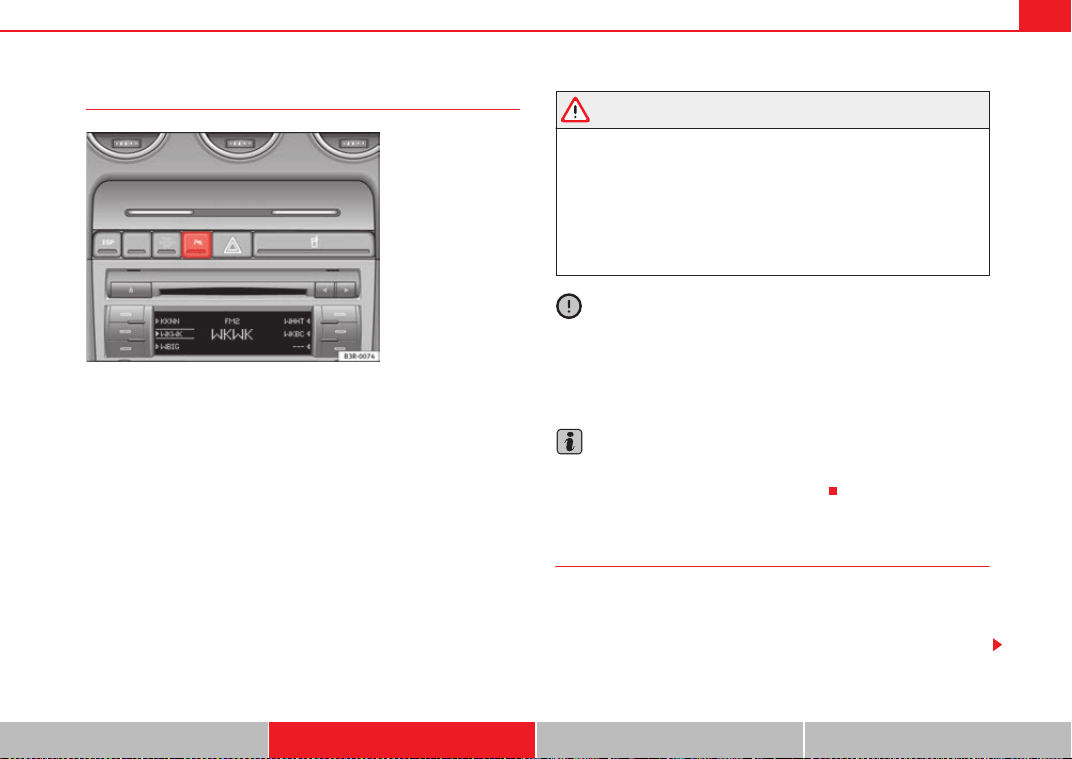
Driving 179
Safety First Operating Instructions Practical Tips Technical Specifications
Activating/Deactivating
Activating
– Engage reverse gear or
– Press the button
on the centre console ⇒ fig. 150 or on the
gear selector gate. You will hear a brief confirmation tone and the
LED on the switch will light up.
Deactivating
– Drive forward faster than 10 km/h, or
–Press the
button or
– Switch off the ignition or
– Disengage the reverse gear.
WARNING
• The parking aid is not a replacement for driver awareness. The driver is
personally responsible for safe parking and other manoeuvres.
• The sensors have blind spots in which obstacles are not registered.
Always look out for small children and animals because the system will not
always detect them. Always pay attention when reversing to avoid acci-
dents.
• Always keep a close eye on the area around the vehicle and make full
use of the rear view mirrors.
Caution
Please note that low obstacles detected by the system may no longer be
registered by the sensors as the vehicle moves closer, so the system will not
give any further warning. Certain kinds of obstacles (such as wire fences,
chains, thin painted posts or trailer draw bars, etc) may not always be
detected by the system, so take care not to damage the vehicle in such cases.
Note
• Please refer to the notes on towing ⇒ page 179.
• There is a slight delay in the picture display.
Towing bracket*
In towing mode, the rear parking aid sensors are not enabled when you select
reverse gear or press the switch
. This function may not be guaranteed on
towing brackets that are not factory fitted. This results in the following restric-
tions:
Fig. 150 Centre console:
switch for parking aid
ExeoST_EN.book Seite 179 Freitag, 3. September 2010 11:41 11
Driving180
SEAT Parking System*
There is no distance warning.
SEAT Parking System Plus*
There is no rear distance warning. The system will still give a warning when
obstacles are detected while driving forward.
Fault messages*
If you hear a long beep for a few seconds and the LED on the button* starts
flashing when you switch on the parking aid, a system fault has occurred.
Please have the fault corrected by a Dealer or qualified workshop.
Note
If the fault is not corrected before you switch off the ignition, it will only be
indicated by the flashing LED on the switch
* the next time you switch on
the parking aid.
Cruise control*
Introduction
The cruise control system allows you to maintain a constant
speed.
Using this system, any speed over 30 km/h can be kept constant, as long as
the engine power allows it. This is subject to power output and braking ability
of the engine. This helps to reduce fatigue, especially on long journeys.
The indicator lamp
on the instrument panel lights up when the cruise
control system is operating.
WARNING
For safety reasons, the cruise control system should not be used in dense
traffic or poor road conditions (with ice, slippery surfaces, loose grit or
gravel), as this could cause an accident.
Caution
In vehicles with a manual gearbox: do not go into neutral if the device is
enabled without previously releasing the clutch, as the engine will increase
its revs and, under certain conditions, could break down.
Note
The cruise control cannot maintain a constant speed when travelling down
steep hills. The vehicle tends to accelerate under its own weight. Change
down to a lower gear or use the foot brake to slow the vehicle.
ExeoST_EN.book Seite 180 Freitag, 3. September 2010 11:41 11
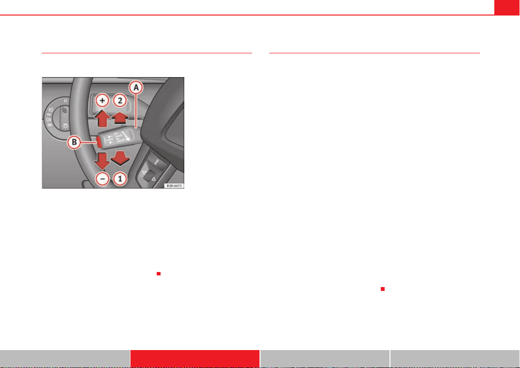
Driving 181
Safety First Operating Instructions Practical Tips Technical Specifications
Setting the speed
The desired cruising speed has to be stored in the memory.
– Drive at the desired speed.
– Pull the lever to position ⇒ fig. 151 to activate the
system.
– Briefly press button .
When button is released, the current speed is stored in the memory and
the vehicle will then maintain this speed.
Adjusting the stored speed
The desired cruising speed can be adjusted up or down as
required.
Acceleration
–Move the lever up towards ⇒ fig. 151 .
– Release the lever to store the current cruising speed.
Deceleration
–Move the lever down towards ⇒ fig. 151 .
– Release the lever to store the current cruising speed.
Pressing lever briefly
– You can increase the set speed in steps of 2 km/h by briefly
pressing the lever up towards ⇒ fig. 151 .
– You can decrease the set speed in steps of 2 km/h by briefly
pressing the lever down towards ⇒ fig. 151 .
You can also use the accelerator pedal momentarily to increase speed. The
previously programmed speed will be automatically resumed when the accel-
erator pedal is released.
However, if the vehicle exceeds the programmed speed by more than 10
km/h for more than 5 minutes, the programmed speed will be deleted. You
will then need to enter the speed again.
Fig. 151 Controls for the
cruise control system
A
A
A
1
A
B
A
B
A
A
A
+
A
A
A
-
A
A
A
A
A
+
A
A
A
-
ExeoST_EN.book Seite 181 Freitag, 3. September 2010 11:41 11
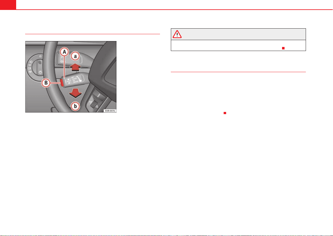
Driving182
Deactivating the cruise control temporarily
–Press the brake pedal or
–The clutch or
–Press the lever ⇒ fig. 152 to position (click stop not
engaged).
– Any intervention of the TCS or the ESP will switch off the cruise
control.
The speed stored at this point remains in the memory if the system is only
temporarily deactivated.
To resume the programmed cruising speed, release the clutch or brake pedal
and pull the lever to position .
If no speed was stored when the system was temporarily disabled, a new
speed can be set as follows: drive at the desired cruising speed and briefly
press button ⇒ page 181, fig. 151 (SET).
WARNING
Retrieve the programmed speed only if this is not excessive for the current
traffic conditions. Failure to do so could result in an accident.
Deactivating the cruise control
While driving
–Move lever ⇒ page 181, fig. 151 to position (click stop
engaged).
While the vehicle is stationary
– Switch the ignition off.
Fig. 152 Controls for the
cruise control system
A
A
A
a
A
A
A
b
A
B
A
A
A
2
ExeoST_EN.book Seite 182 Freitag, 3. September 2010 11:41 11
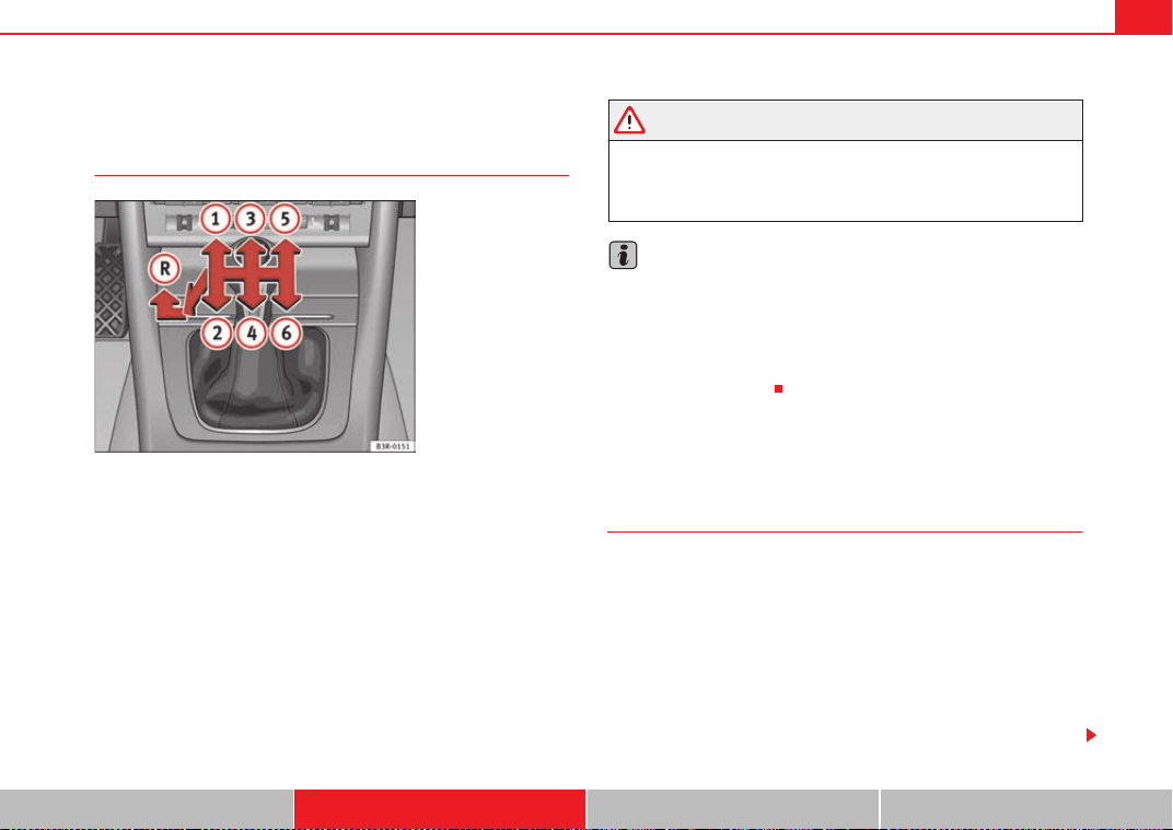
Driving 183
Safety First Operating Instructions Practical Tips Technical Specifications
Manual gearbox
Driving with a manual gearbox
Engaging the reverse gear
– The vehicle should be stationary with the engine idling. Press the
clutch down thoroughly.
– Place the gear lever into neutral and push the lever downwards.
– Slide the gear lever to the left, and then into the reverse position
shown on the gear lever.
The reverse gear can only be engaged when the vehicle is stationary. When
the engine is running and before engaging this gear, wait about 6 seconds
with the clutch pressed down thoroughly in order to protect the gearbox.
The reverse lights light up when the reverse gear is selected and the ignition
is on.
WARNING
• When the engine is running, the vehicle will start to move as soon as a
gear is engaged and the clutch released.
• Never select the reverse gear when the vehicle is in motion. Risk of acci-
dent.
Note
• Do not rest your hand on the gear lever while driving. The pressure of your
hand could cause premature wear on the selector forks in the gearbox.
• When changing gear, you should always depress the clutch fully to avoid
unnecessary wear and damage.
• Do not hold the vehicle on the clutch on hills. This causes premature wear
and damage to the clutch.
Automatic gearbox*
Introduction
multitronic
®
, tiptronic (7-speed gearbox)
Vehicles with multitronic
®
gearbox
The vehicle is equipped with an electronically controlled continuously vari-
able transmission (multitronic
®
). Unlike conventional automatics, the gear
ratios are not shifted in fixed steps but continuously variable. This gives
smoother transmission and makes for better fuel economy.
The gearbox selects the gear ratio and shifts up or down automatically
according to the gear change programmes stored in the control unit
⇒ page 188.
Fig. 153 Detailed view of
the centre console: gear
shift pattern of a 6-speed
manual gearbox
ExeoST_EN.book Seite 183 Freitag, 3. September 2010 11:41 11
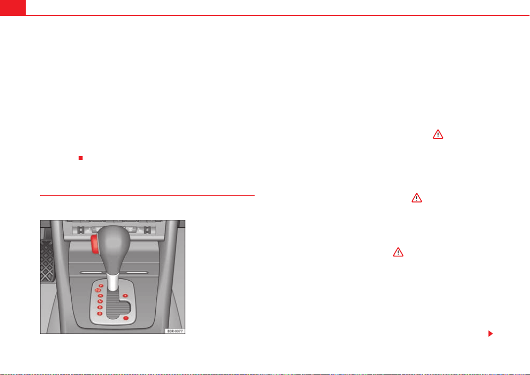
Driving184
If desired, you can also select the gears manually (tiptronic mode)
⇒ page 189.
Please note that in vehicles with a multitronic® gearbox, torque is trans-
mitted via a multi-plate clutch, and not via a torque converter as on conven-
tional automatics. This means that the vehicle will not “creep” as much as
conventional automatics when the engine is idling if you stop temporarily
with the selector lever in position D, S or R.
Vehicles with tiptronic gearbox
The vehicle is equipped with an electronically controlled 7-speed automatic
gearbox. The gearbox changes up and down automatically.
If desired, you can also select the gears manually (tiptronic mode)
⇒ page 189.
Driving instructions
The gears are changed automatically.
Starting the vehicle
–Press and hold the brake pedal.
– Press and hold the interlock button (the button on the selector
lever handle), move the selector lever to the desired position, for
instance D, and release the interlock button.
– Wait for the gearbox to engage the gear (a slight movement can
be felt).
– Release the brake and press the accelerator ⇒ .
Stopping briefly
– Apply the foot brake to hold the vehicle when stationary (for
instance at traffic lights).
– To prevent the vehicle from rolling away, apply the parking brake
before moving off on steep gradients ⇒ .
– As soon as you accelerate as normal, the parking brake will auto-
matically be released and the vehicle will start moving.
Parking the vehicle
–Press and hold the brake pedal ⇒ .
– Apply the parking brake.
– Press and hold the interlock button, move the selector lever to P
and release the interlock button.
The engine can only be started when the selector lever is at P or N.
On level ground it is sufficient to move the selector lever to P. On slopes, first
engage the parking brake and then put the selection lever into the P position.
Fig. 154 Detailed view of
the centre console:
Selector lever with lock
button
ExeoST_EN.book Seite 184 Freitag, 3. September 2010 11:41 11
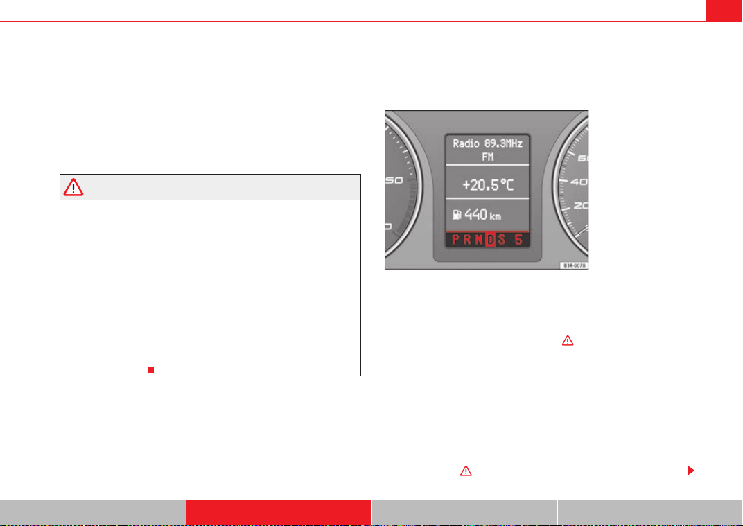
Driving 185
Safety First Operating Instructions Practical Tips Technical Specifications
This avoids overloading the locking mechanism and it will be easier to move
the selector lever from position P.
Vehicles with multitronic® gearbox: Your vehicle is equipped with the hill
hold assist function which makes it easier to start off on a slope. The system
is activated when you press and hold the brake pedal for a few seconds.
When you release the brake pedal the braking force will be maintained for a
short moment in order to prevent the vehicle rolling back when you drive
away.
WARNING
• While you are selecting a gear and the vehicle is stopped with the
engine running, do not accelerate. Failure to do so could result in an acci-
dent.
• Please note that some power will still be transmitted when you stop
temporarily with the selector lever in position D, S or R. Therefore, when
stopping you will need to press the brake with the force required to hold
the vehicle still. Failure to do so could result in an accident.
• Never move the selector lever to R or P when driving, as this could cause
an accident.
• Vehicles with multitronic® gearbox: Please note that some power will
still be transmitted when you stop temporarily with the selector lever in
position D, S or R. Therefore, when stopping you will need to press the
brake with the force required to hold the vehicle still. Failure to do so could
result in an accident.
Selector lever positions
This section covers all the selector lever positions.
The current selector lever position is shown on the instrument panel display.
P - parking lock
This locks the driving wheels mechanically. The parking brake should only be
used when the vehicle is already stopped ⇒ .
The interlock button (the button on the selector lever handle) must be
pressed in and the brake pedal must be depressed before moving the
selector lever either in or out of position P. This is only possible when the igni-
tion is on.
R - Reverse gear
When reverse gear is engaged the gearbox automatically selects the lowest
gear ratio.
The reverse gear may be engaged only when the vehicle is stationary and the
engine is idling ⇒ .
Fig. 155 Display:
Selector lever positions
ExeoST_EN.book Seite 185 Freitag, 3. September 2010 11:41 11
Driving186
To move the selector lever to position R, press in the interlock button and at
the same time press the brake pedal. Depending on the model, one or two
reverse lights will come on in selector lever position R (when ignition is
switched on).
N - Neutral (idling)
In this position the gearbox is in neutral ⇒ .
D - Drive (forward)
In this position, the gearbox selects the optimal transmission ratio
depending on the engine load, speed and the dynamic gear regulation
programme (DRP).
Press the brake pedal when moving the selector lever from N to D if the
vehicle is stationary or at speeds below 5 km/h ⇒ .
Under certain circumstances (e.g. when driving in mountains or towing a
trailer or caravan) it can be advantageous to switch temporarily to tiptronic
mode ⇒ page 189, so that the gear ratios can be selected manually to suit
the driving conditions.
S - Sport position
To drive in sports mode, select the position S. The engine power reserve is
used to its maximum. When accelerating the gear shifts will be noticeable.
Press the brake pedal when moving the selector lever from N to S if the
vehicle is stationary or at speeds below 5 km/h ⇒ .
WARNING
• Never move the selector lever to R or P when driving. Failure to do so
could result in an accident.
• In selector position D or S the vehicle must always be held with the foot
brake when the engine is running. This is because an automatic gearbox
still transmits power even at idling speed, and the vehicle tends to “creep”.
The throttle must on no account be opened inadvertently (for instance by
hand from the engine compartment) when a gear is engaged with the
vehicle stationary. The vehicle could otherwise start moving immediately
(in some cases even if the parking brake is engaged) and possibly cause an
accident.
• To avoid accidents, apply the parking brake and put the selector lever
in position P before opening the bonnet and working on the vehicle with
the engine running. Please observe the important safety warnings
⇒ page 229, “Work in the engine compartment”.
Note
• Applies to vehicles with tiptronic gearbox:
• If the lever is moved accidentally to N when driving, release the acceler-
ator and let the engine speed drop to idling before selecting D or S again.
• For the sake of fuel economy (and the environment), the gearbox ratios on
some models are designed so that maximum speed is only obtained when
the gear lever is in position S.
WARNING (continued)
ExeoST_EN.book Seite 186 Freitag, 3. September 2010 11:41 11
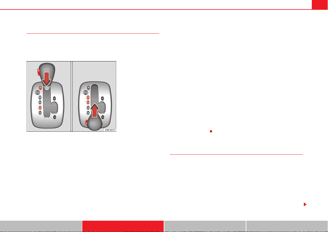
Driving 187
Safety First Operating Instructions Practical Tips Technical Specifications
Selector lever lock
The selector lever lock prevents gears from being engaged
inadvertently, so that the vehicle is not set in motion uninten-
tionally.
The selector lever lock is released as follows:
– Switch the ignition on.
–Press the brake pedal and at the same time press in the interlock
button.
Automatic selector lever lock
With the ignition turned on, the selector lever is locked in the positions P and
N. To remove it from these positions, press on the brake. The following
message appears in the instrument panel as a reminder for the driver when
the selector lever is in position P or N:
WHEN STATIONARY APPLY FOOTBRAKE WHILE SELECTING GEAR
The selector lever lock only works if the vehicle is stationary or driving at
speeds up to 5 km/h. At higher speeds the selector lever lock in the N posi-
tion is disengaged automatically.
The selector lever lock is not engaged if the selector lever is moved quickly
through position N (e.g. when shifting from R to D). This makes it possible, for
instance, to “rock” the vehicle backwards and forwards if it is stuck in snow
or mud. The selector lever lock engages automatically if the brake pedal is not
depressed and the lever is in position N for more than about a second.
Interlock button
The interlock button on the selector lever handle prevents the driver from
inadvertently engaging particular gears. Press the button in to disengage the
selector lever lock. The selector lever positions in which the interlock button
has to be pressed are shown in the illustration, highlighted in colour
⇒ fig. 156.
Safety interlock for ignition key
Once the ignition has been turned off, the key may be removed only if the gear
selector is in position P. While the key is not in the ignition, the selector lever
is locked in position P.
Kick-down feature
The kickdown feature is designed to give maximum accelera-
tion.
Vehicles with multitronic
®
gearbox
When the accelerator pedal is pressed right down past the point of resistance
at full throttle, the gearbox will select a lower gear ratio, depending on road
speed and engine speed. While you keep the accelerator depressed the
engine speed is automatically controlled to give your vehicle maximum accel-
eration.
Fig. 156 Selector lever
lock functions
ExeoST_EN.book Seite 187 Freitag, 3. September 2010 11:41 11
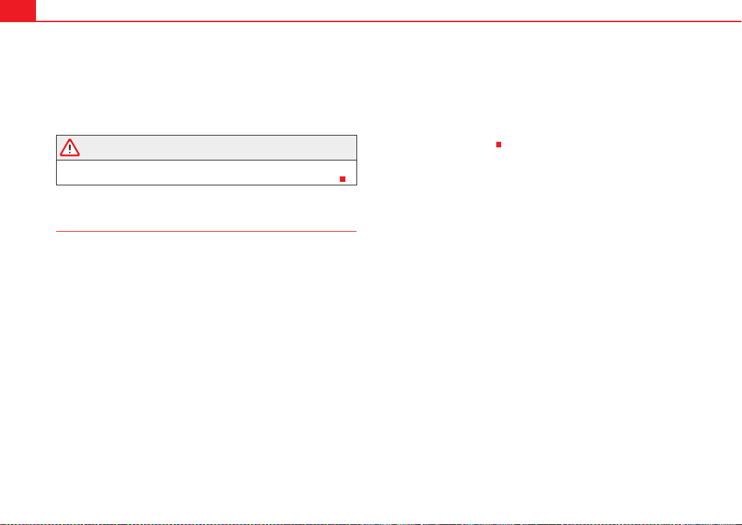
Driving188
Vehicles with tiptronic gearbox
When the accelerator pedal is pressed right down past the point of resistance
at full throttle, the gearbox will shift down to a lower gear, depending on road
speed and engine speed. The upshift to the next higher gear is delayed until
the engine reaches maximum rpm.
WARNING
Please note that if the road surface is slippery or wet, the kick-down feature
could cause the driving wheels to spin, which could result in skidding.
Dynamic gear control programme (DCP)
The automatic gearbox is controlled electronically.
The vehicle is equipped with an electronically controlled gearbox. The gear
ratios are selected automatically according to preset gearshift programmes.
When you drive at moderate speeds the gearbox will select the most econom-
ical shift programme. It will then change up early and delay the downshifts to
give better fuel economy.
If you drive at higher speedswith heavy acceleration, if you open the throttle
quickly, or if you use the kick-down or the vehicle's maximum speed, the
gearbox will automatically select the sport programme.
The gearbox is self-adapting, and continuously selects the most suitable shift
programme. At the same time, the driver can also make the gearbox switch to
the sport programme by pressing the accelerator quickly. This makes the
gearbox shift down into a lower gear ratio, allowing a more rapid acceleration
(for instance to pass another vehicle), without having to press the accelerator
all the way down into the kick-down position. After the gearbox has shifted
back up it returns to the original programme, depending on your style of
driving.
Vehicles with multitronic® gearbox: the gearbox continuously adapts the
gear ratios to gradients. If the brake pedal is pressed on a downhill gradient
the gearbox automatically shifts to a lower gear ratio. This increases the
engine braking effect.
Vehicles with tiptronic gearbox: in mountainous areas, the gearbox adapts
the gears for uphill and downhill gradients. This helps to avoid constant gear
changes on uphill gradients.
ExeoST_EN.book Seite 188 Freitag, 3. September 2010 11:41 11
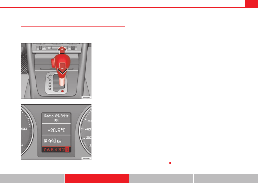
Driving 189
Safety First Operating Instructions Practical Tips Technical Specifications
Manual gear selection (tiptronic mode)
With the manual shift programme (tiptronic) the driver can
manually select pre-programmed gears.
Switching over to the manual programme
– Move the selector lever from the position D to the right-hand
side. As soon as the selector lever has entered the tiptronic rail,
the gear engaged is displayed on the screen.
Shifting up a gear
– Briefly push the selector lever forwards (in the tiptronic gate)
⇒ fig. 157 .
Shifting down a gear
– Briefly pull the selector lever backwards (in the tiptronic gate)
.
With the tiptronic system, the driver can manually choose between eight (in
vehicles with multitronic) or seven (in vehicles with tiptronic) different gear
programmes. The manual programme can be selected either with the vehicle
stationary or on the move.
When accelerating, the gearbox automatically shifts up into the next gear
shortly before the maximum engine speed is reached.
If you select a gear which is lower than the gear shown on the instrument
panel display ⇒ fig. 158, the gearbox will only shift down when there is no
longer a risk of over-revving the engine.
When the vehicle slows down (for instance when braking), the gearbox auto-
matically shifts down into the next gear when the minimum engine speed is
reached.
Changing down to a lower gear increases the engine braking effect on down-
hill gradients.
When the accelerator pedal is pressed right down past the point of resistance
at full throttle, the gearbox will select a lower gear ratio, depending on road
speed and engine speed.
Fig. 157 Centre console:
Manual gear selection
(tiptronic mode)
Fig. 158 Display: Manual
gear selection (tiptronic
mode)
A
+
A
-
ExeoST_EN.book Seite 189 Freitag, 3. September 2010 11:41 11
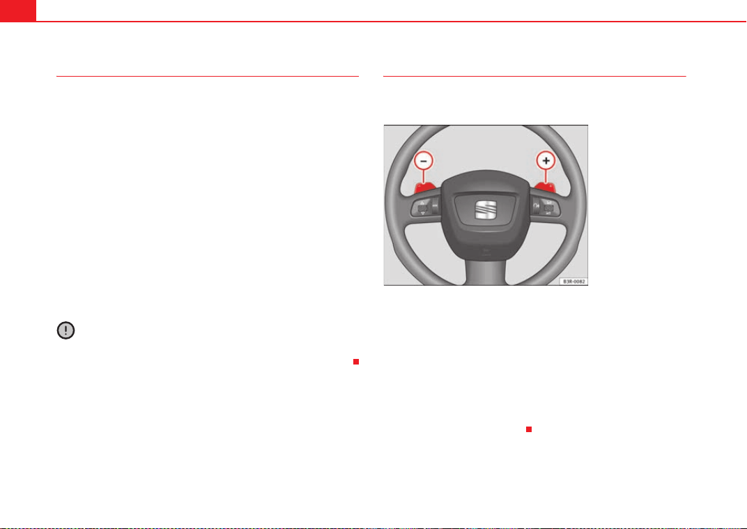
Driving190
Back-up programme
A back-up system is in place if a fault should occur in the
control system.
The automatic gearbox switches to the back-up programme if a fault should
occur in the control system. This is indicated by a gear pinion symbol which
lights up on the instrument panel display.
It is still possible to move the selector lever to all positions. The manual shift
programme (tiptronic) is not available when the back-up programme is
active.
Vehicles with tiptronic gearbox: when the selector lever is in position D or S
or in the manual shift programme, the gearbox will remain in 3rd gear if 1st,
2nd or 3rd gears were engaged when the fault occurred. The gearbox will
remain in 5th gear if 4th, 5th or 6th gears were engaged. The gearbox will
then engage 3rd gear when you drive away from a standstill or after the
engine is restarted.
It will still be possible to use reverse gear in the normal way. However, the
electronic lock for reverse gear will be switched off.
Caution
Should the gearbox ever switch into the back-up programme, you should take
the vehicle to a technical service or qualified workshop as soon as possible.
Steering wheel with paddle levers
The paddle levers on the steering wheel enable the driver to
manually select pre-programmed ratios or gears.
– Briefly pull the left-hand paddle lever to change down to a
lower gear.
– Briefly pull the right-hand paddle lever to change up to a
higher gear.
The paddle levers are activated when the selector lever is in position D or S,
or the position for the manual shift programme (tiptronic).
The manual shift programme can, of course, still be operated using the
selector lever in the centre console.
Fig. 159 Steering wheel:
tiptronic controls
A
–
A
+
ExeoST_EN.book Seite 190 Freitag, 3. September 2010 11:41 11
Intelligent technology 191
Safety First Operating Instructions Practical Tips Technical Specifications
Practical Tips
Intelligent technology
Electronic Stability Programme (ESP)
General notes
The Electronic Stability Programme increases the vehicle's
stability on the road.
The ESP is designed to increase the degree of control in situations where the
vehicle approaches the limits of adhesion, especially when accelerating and
cornering. It reduces the risk of skidding and improves stability in all road
conditions. The system is active across the entire speed range.
The anti-lock brake system (ABS), the electronic differential lock (EDL) and
the traction control system (TCS) are all integrated into the Electronic Stability
Programme.
How it works
The ESP control unit processes data from the three integrated systems. It also
processes additional inputs provided by other high-precision sensors. These
register the vehicle's rotation about the vertical axis (yaw rate), lateral accel-
eration, brake pressure and steering wheel angle.
The system uses the steering wheel angle and road speed to calculate the
changes of direction desired by the driver, and constantly compares them
with the actual behaviour of the vehicle. If the desired course is not being
maintained (for instance, if the vehicle is starting to skid), then the ESP
compensates automatically by braking the appropriate wheel.
The forces acting on the braked wheel bring the vehicle back to a stable
condition. If the vehicle over swerves (tendency of the rear to leave the road),
the brakes will act on the front wheel facing the outside of the bend. If the
vehicle under swerves (tendency to leave the bend), the braking force is
applied to the rear wheel facing the inside of the bend.
The ESP works in conjunction with the ABS ⇒ page 192. If a malfunction
should occur in the ABS, the ESP will also stop working.
Deactivating
The ESP is activated automatically when the engine is started and performs a
self-test routine.
Fig. 160 Centre console
with ESP switch
ExeoST_EN.book Seite 191 Freitag, 3. September 2010 11:41 11
Intelligent technology192
If required, the ESP can also be enabled and disabled manually by briefly
pressing the button ⇒ page 191, fig. 160. The ESP warning lamp lights
up when the system is switched off, see ⇒ page 68.
In general, the ESP should be left switched on at all times. In particular
circumstances where a certain amount of wheel slip is desirable, it may be
advisable to switch off the ESP. Examples:
• when driving with snow chains
• when driving in deep snow or on loose surfaces
• when rocking the vehicle backwards and forwards to free it.
The ESP should be switched on again afterwards as soon as possible.
WARNING
The ESP is not able to overcome the physical limits of adhesion. Even with
ESP, you should always adjust your speed to suit the conditions. Please
bear this in mind, especially on wet or slippery road surfaces. Do not let the
extra safety features tempt you into taking any risks when driving. Failure
to do so could result in an accident.
Anti-lock brake system (ABS)
ABS prevents the wheels from locking up under braking.
The anti-lock brake system (ABS) is an important part of the vehicle's active
safety system. However, the ABS will not necessarily guarantee shorter stop-
ping distances in all conditions. For instance, on loose gravel or fresh snow
on top of an icy surface (conditions which anyway require extreme care and
reduced speed), the stopping distance with ABS may even be slightly longer.
How the ABS works
The system runs an automatic self-check when the vehicle reaches a road
speed of about 6 km/h. This may be accompanied by a noise from the ABS
pump.
When one of the wheels is turning very slowly in relation to the road speed
and is close to locking up, the system will reduce the brake pressure on that
wheel. The driver is made aware of this adjustment process by a vibration of
the brake pedal and an audible noise. This is a deliberate warning to the
driver that one or more of the wheels is tending to lock up and the ABS control
function has intervened. In this situation it is important to keep the brake
pedal fully depressed so the ABS can regulate the brake application, but do
not “pump” the brake pedal.
WARNING
The grip provided by ABS is still subject to the physical limits of adhesion.
Always bear this in mind, especially on wet or slippery roads. If you notice
that the ABS is working (to counteract locked wheels under braking), you
should reduce speed immediately to suit the road and traffic conditions. Do
not let the extra safety features tempt you into taking any risks when
driving. Failure to do so could result in an accident.
Note
If a malfunction should occur in the ABS, this is indicated by a warning lamp
⇒ page 67.
ESP
ExeoST_EN.book Seite 192 Freitag, 3. September 2010 11:41 11
Intelligent technology 193
Safety First Operating Instructions Practical Tips Technical Specifications
Brake assist system
The brake assist system helps the driver to achieve optimum
braking effect.
The brake assist system helps to increase braking power and thus to achieve
a shorter stopping distance. If the driver presses the brake pedal very quickly,
the brake assist system automatically boosts the braking force to the
maximum level, up to the point where the anti-lock brake function (ABS) inter-
venes to stop the wheels from locking. You should then keep the brake pedal
pressed until the vehicle has braked to the required speed. The brake assist
system switches itself off as soon as you release the brake pedal.
The brake assist system will not be operative if there is a malfunction in the
ABS or the ESP.
WARNING
Please remember that the accident risk always increases if you drive too
fast, especially in corners or on a slippery road, or if you follow too close
behind the vehicle in front of you. An increased accident risk cannot be
compensated even by the brake assist system.
Electronic differential lock (EDL)
The electronic differential lock prevents the loss of traction
caused if one wheel starts spinning.
General notes
The electronic differential lock (EDL) helps the vehicle to start moving, accel-
erate and climb a gradient in slippery conditions where this may otherwise be
difficult or even impossible.
How it works
The EDL works automatically, without the driver's involvement. With the aid
of the ABS sensors, the system monitors the rotational speed of the drive
wheels ⇒ page 192. If a considerable difference in revs is detected (approx.
100 rpm) in the speed of the drive wheels, e.g. when only one part of the
surface supporting the wheels is slippery, the system applies the brake to
slow down the skidding wheel so that more of the power is directed to the
other wheels. The systems works up to a speed of approx. 80 km/h. The
system will make noise while it is working.
Starting the vehicle
If one wheel has less grip and starts spinning (for instance, if one of the drive
wheels is on ice), keep pressing the accelerator gradually until the vehicle
starts moving.
Overheating of the brakes
To prevent the brake disk of the braked wheel from overheating, the EDL cuts
out automatically if subjected to excessive loads. In this case, the vehicle will
continue to run and will have the same running properties as those of another
without EDL.
The EDL will switch on again automatically when the brake has cooled down.
WARNING
• When accelerating on a uniformly slippery surface (for instance all four
wheels on ice or snow), press the accelerator gradually and carefully.
Despite EDL, the drive wheels may otherwise start to spin. This could
impair the vehicle's stability. Risk of accident.
• Even with EDL, you should always adjust your speed to suit the road and
traffic conditions. Do not let the extra safety features tempt you into taking
any risks when driving. Failure to do so could result in an accident.
ExeoST_EN.book Seite 193 Freitag, 3. September 2010 11:41 11

Intelligent technology194
Note
If the ABS warning lamp lights up, this can also mean there is a fault in the
EDL. Please take the vehicle to a qualified workshop as soon as possible.
Traction control system (TCS)
The traction control system prevents the drive wheels from
spinning when the vehicle is accelerating.
General notes
The traction control system (TCS) is one of the functions incorporated in the
Electronic Stability Programme (ESP).
The traction control system (TCS) helps the vehicle to start moving, accelerate
or climb a gradient in slippery conditions where this may otherwise be diffi-
cult or even impossible.
How it works
The TCS acts automatically, without the driver's intervention. With the aid of
the ABS sensors ⇒ page 192, the TCS monitors the speed of the drive
wheels. If the wheels start to spin, the engine speed is reduced automatically
to match the amount of grip available. The system is active across the entire
speed range.
The TCS works in conjunction with the ABS. If a malfunction occurs in the ABS,
the TCS will also be inoperative.
Note
To ensure that the TCS works properly, all four wheels must be fitted with
identical tyres. The difference in size of the wheels may lead to an undesired
reduction in engine power. Also see ⇒ page 251.
Brakes
General notes
New brake pads
New brake pads do not provide optimal performance during the first 200 km;
first they must be “run in”. However, the reduced braking capacity may be
compensated by pressing on the brake pedal a little harder. Avoid over-
loading the brakes during run-in.
Wear
The rate of wear on the brake pads depends a great deal on how you drive and
the conditions in which the vehicle is operated. Negative factors are, for
instance, city traffic, frequent short trips or hard driving with abrupt starts
and stops.
Wet roads or road salt
In certain conditions, such as in heavy rain, or after washing the vehicle or
driving through water, the full braking effect can be delayed by moisture (or
in winter by ice) on the discs and brake pads. In this case the brakes should
be dried by pressing the brake pedal several times.
When the speed is over 80 km/h and the windscreen wipers are on, the brake
system moves the pads towards the brake discs for a few seconds. This
occurs - without the driver knowing - at regular intervals and allows a faster
response from the brakes when driving on wet roads.
The effectiveness of the brakes can also be temporarily reduced if the vehicle
is driven for some distance without using the brakes when there is a lot of salt
on the road in winter. In this case, the layer of salt on the brake discs and pads
has to wear off before braking.
ExeoST_EN.book Seite 194 Freitag, 3. September 2010 11:41 11
Intelligent technology 195
Safety First Operating Instructions Practical Tips Technical Specifications
Corrosion
There may be a tendency for corrosion to form on the discs and dirt to build
up on the brake pads if the vehicle is used infrequently or the brakes are not
used very often.
If the brakes are not used frequently, or if rust has formed on the disks, it is
advisable to clean off the pads and disks by braking firmly a few times at a
moderately high speed ⇒ .
Faults in the brake system
If the brake pedal travel should ever increase suddenly, this may mean that
one of the two brake circuits has failed. Drive immediately to the nearest
specialised workshop and have the fault repaired. Drive there slowly and
remember that you will have to apply more pressure on the brake pedal and
allow for longer stopping distances.
Low brake fluid level
Malfunctions can occur in the brake system if the brake fluid level is too low.
The brake fluid level is monitored electronically.
WARNING
When applying the brakes to clean off deposits on the pads and discs,
select a clear, dry road. Be sure not to inconvenience or endanger other
road users. Risk of accident.
Caution
• Never let the brakes “drag” by leaving your foot on the pedal when it is
not necessary to brake. This overheats the brakes, resulting in longer stop-
ping distances and greater wear.
• Before driving down a long, steep gradient, it is advisable to reduce speed
and change to a lower gear (or move the gear lever to a lower gear position if
your vehicle has automatic transmission). This makes use of engine braking
and prolongs the service life of the brakes. If you still have to use the brakes,
it is better to brake firmly at intervals than to apply the brakes continuously.
Note
If you wish to equip the vehicle with accessories such as a front spoiler or
wheel covers, it is important that the flow of air to the front wheels is not
obstructed, otherwise the brakes can overheat.
Brake servo
The brake servo assists the driver when braking
The brake servo increases the pressure you apply to the brake pedal. The
brake servo works only when the engine is running.
WARNING
Ensure the vehicle does not move while in neutral, when the engine is
stopped. Failure to do so could result in an accident.
Note
If the brake servo is not working, e.g. because the vehicle has to be towed or
because it is broken, you will have to press the brake pedal considerably
harder to make up for the lack of servo assistance.
ExeoST_EN.book Seite 195 Freitag, 3. September 2010 11:41 11
Intelligent technology196
Power steering
Power steering makes it easier to turn the steering wheel
when the engine is running.
Power steering assists the driver by reducing the force needed to turn the
steering wheel.
Power steering does not work if the engine is off. In this case the steering
wheel requires much more force to turn.
If the steering is held at its turning limit when the vehicle is stationary, this
will place an excessive load on the power steering system. Turning the
steering wheel to its limit places a load on the system, which causes noise. It
will also reduce the idling speed of the engine.
Caution
When the engine is running, do not turn the steering wheel to its limit for
more than 15 seconds. Otherwise, there is a risk of damaging the power
steering.
Note
• If the power steering should fail at any time or the engine is switched off
(for instance when being towed), the vehicle can still be steered. However,
more effort will be required to turn the steering wheel.
• If the system is leaking or malfunctioning, please take the vehicle to a
qualified workshop as soon as possible.
• The power steering system requires a special hydraulic fluid. The fluid
reservoir is located at the front of the engine compartment on the left
⇒ page 301. The correct fluid level in the reservoir is important for the power
steering to function properly. The hydraulic fluid level is checked at the
Inspection Service.
Servotronic*
The servotronic system electronically adjusts the power
assisted steering.
In vehicles equipped with servotronic power steering the degree of power
assistance ⇒ page 196 is adjusted electronically according to road speed.
If a fault should occur in the servotronic system, the power steering will still
operate. The degree of power assistance will, however, no longer adapt to
different speeds. If the electronic regulating system is not working properly,
this is most noticeable when turning the steering wheel at low speeds (for
instance when parking), as more effort will be required than usual. The fault
should be corrected by a qualified workshop as soon as possible.
ExeoST_EN.book Seite 196 Freitag, 3. September 2010 11:41 11

Driving and the environment 197
Safety First Operating Instructions Practical Tips Technical Specifications
Driving and the environment
Running-in
Running in a new engine
The engine needs to be run in over the first 1500 km.
Up to 1000 kilometres
– Do not drive at speeds of more than 2/3 the maximum speed.
– Do not accelerate hard.
– Avoid high engine revolutions.
– Do not tow a trailer.
From 1000 to 1500 kilometres
– Speeds can be gradually increased to the maximum road speed
or maximum permissible engine speed (rpm).
During its first few hours of running, the internal friction in the engine is
greater than later on, when all the moving parts have bedded in.
For the sake of the environment
If the engine is run in gently, its life will be increased and its oil consumption
reduced.
Braking capacity and braking distance
The braking capacity and braking distance are influenced by
driving situations and road conditions.
The efficiency of the brakes depends directly on the brake pad wear. The rate
of wear of the brake pads depends to a great extent on the conditions under
which the vehicle is operated and the way the vehicle is driven. If you often
drive in town traffic, drive short distances or have a sporty driving style, we
recommend that you have the thickness of your brake pads checked by an
Authorised Service Centre more frequently than recommended in the Service
Plan.
If you drive with wet brakes, for example, after crossing areas of water, in
heavy rainfall or even after washing the vehicle, the effect of the brakes is
lessened as the brake discs are wet or even frozen (in winter). In this case the
brakes should be dried by pressing the brake pedal several times.
WARNING
Longer braking distances and faults in the brake system increase the risk
of accidents.
• New brake pads must be run in and do not have the correct friction
during the first 200 km. However, the reduced braking capacity may be
compensated by pressing on the brake pedal a little harder. This also
applies when the brake pads have to be changed further on.
• If brakes are wet or frozen, or if you are driving on roads which have
been salted, braking power may be lower than normal.
• On steep slopes, if brakes are excessively used, they will overheat.
Before driving down a long steep slope, it is advisable to reduce speed and
ExeoST_EN.book Seite 197 Freitag, 3. September 2010 11:41 11
Driving and the environment198
change down into a lower gear or range (depending on the type of trans-
mission). This makes use of engine braking and relieves the brakes.
• Never let the brakes “drag” by applying light pressure. Continuous
braking will cause the brakes to overheat and the braking distance will
increase. Apply and then release the brakes alternately.
• Never let the vehicle run with the engine switched off. The braking
distance is increased considerably when the brake servo is not active.
• If the brake fluid loses its viscosity and is subjected to heavy use,
vapour bubbles can form in the brake system. This reduces the efficiency of
the brakes.
• Non-standard or damaged front spoilers could restrict the airflow to the
brakes and cause them to overheat. Before purchasing accessories please
observe the relevant instructions ⇒ page 223, “Technical modifications”.
• If a brake circuit fails, the braking distance will be increased consider-
ably. Contact a qualified workshop immediately and avoid unnecessary
journeys.
Exhaust gas purification system
Catalytic converter*
To maintain the useful life of the catalytic converter
– Use only unleaded petrol with petrol engines, as lead damages
the catalytic converter.
– Do not let the fuel get too low in the tank.
– For engine oil changes, do not replenish with too much engine oil
⇒ page 232.
– Never tow the vehicle to start it, use jump leads if necessary
⇒ page 291.
If you notice misfiring, uneven running or loss of power when the vehicle is
moving, reduce speed immediately and have the vehicle inspected at the
nearest qualified workshop. In general, the exhaust gas warning lamp will
light up when any of the described symptoms occur ⇒ page 66. If this
happens, unburnt fuel can enter the exhaust system and escape into the envi-
ronment. The catalytic converter can also be damaged by overheating.
WARNING
The catalytic converter reaches very high temperatures! There is a risk of
fire.
• Never park where the catalytic converter could come into contact with
dry grass or flammable materials under the vehicle.
• Do not apply additional underseal or anti-corrosion coatings to the
exhaust pipes, catalytic converter or the heat shields on the exhaust
system. These materials could catch fire when the vehicle is being driven.
Caution
Never run the fuel tank completely dry because the irregularity of the fuel
supply may cause ignition problems. This allows unburnt fuel to enter the
exhaust system, which could cause overheating and damage the catalytic
converter.
For the sake of the environment
Even when the emission control system is working perfectly, there may be a
smell of sulphur from the exhaust gas under some conditions. This depends
WARNING (continued)
ExeoST_EN.book Seite 198 Freitag, 3. September 2010 11:41 11
Driving and the environment 199
Safety First Operating Instructions Practical Tips Technical Specifications
on the sulphur content of the fuel used. Quite often the problem can be
solved by changing to another brand of fuel.
Diesel engine particulate filter*
The diesel engine particulate filter eliminates soot produced
by burning diesel.
The diesel engine particulate filter eliminates most of the soot from the
exhaust gas system. Under normal driving conditions, the filter cleans itself.
If the driving conditions do not allow the filter to clean itself (for example,
multiple short trips) the filter will be obstructed by dust and pollen and the
indicator
for the diesel engine particulate filter indicator will light up. This
does not represent a fault, it is a warning that indicates that the filter has not
been able to regenerate automatically and that you must carry out a cleaning
cycle, as indicated in ⇒ page 80.
WARNING
• The diesel engine particulate filter may reach extremely high tempera-
tures; the vehicle should be parked so that the exhaust pipe does not come
into contact with flammable materials underneath the vehicle. Otherwise
there is a risk of fire.
Caution
• Your vehicle is not designed to use biodiesel fuel. Never, under any
circumstances refuel with biodiesel. The use of biodiesel fuel could damage
the engine and the fuel system. The addition of biodiesel to diesel by the
diesel producer in accordance with standard EN 590 is authorised and will
not cause damage to the engine or the fuel system.
• Using diesel fuel with a high sulphur content may significantly reduce the
working life of the diesel particulate filter. Your Authorised Service Centre will
be able to tell you which countries have diesel with a high sulphur content.
Economical and environmentally friendly
driving
Economical and environmentally friendly driving
Fuel consumption, environmental pollution and wear to the engine, brakes
and tyres depends in large part on your driving style. By adopting an econom-
ical driving style and anticipating the traffic situation ahead, you can easily
reduce fuel consumption by 10-15%. Some tips on how to help you reduce
pollution while saving money are listed below.
Drive anticipating the traffic situation
A vehicle uses most fuel when accelerating. When you anticipate the situa-
tion, you have to brake less often and, thus, accelerate less. If it is possible,
let the vehicle roll with a gear engaged, for example, if you see a red light
ahead. The braking effect achieved in this way helps to reduce the wear of
brakes and tyres; emissions and fuel consumption are reduced to zero
(disconnection due to inertia).
Change gear early to save energy
An effective way of saving fuel is to change up quickly through the gears.
Running the engine at high rpm in the lower gears uses an unnecessary
amount of fuel.
Manual gearbox: Change from first to second gear as quickly as possible. We
recommend that, whenever possible, you change to a higher gear upon
reaching 2000 rpm. Follow the recommended gear indication that appears on
the instrument panel ⇒ page 73.
ExeoST_EN.book Seite 199 Freitag, 3. September 2010 11:41 11
Driving and the environment200
Avoid driving at high speed
We advise you not to drive at the top speed permitted by the vehicle. Fuel
consumption, exhaust emissions and noise levels all increase very rapidly at
higher speeds. Driving at moderate speeds will help to save fuel.
Avoid idling
It is worthwhile switching off the engine when waiting in a traffic jam, at level
crossings or at traffic lights with a long red phase. The fuel saved after only
30 - 40 seconds is greater than the amount of fuel needed to restart the
engine.
The engine takes a very long time to warm up when it is running at idling
speed. Mechanical wear and pollutant emissions are also especially high
during this initial warm-up phase. It is therefore best to drive off immediately
after starting the engine. Avoid running the engine at high speed.
Periodic maintenance
Periodic maintenance work guarantees that, before beginning a journey, you
will not consume more than the required amount of fuel. A well-serviced
engine gives you the benefit of improved fuel efficiency as well as maximum
reliability and an enhanced resale value.
A badly serviced engine can consume up to 10% more fuel than necessary.
Avoid short journeys
To reduce the consumption and emission of polluting gases, the engine and
the exhaust filtration systems should reach the optimum service tempera-
ture.
With the engine cold, fuel consumption is proportionally higher. The engine
does not warm up and fuel consumption does not normalise until having
driven approximately four kilometres. This is why we recommend avoiding
short trips whenever possible.
Maintain the correct tyre pressures
Bear in mind that keeping the tyres at an adequate pressure saves fuel. If the
tyre pressure is just 1 bar too low, fuel consumption can increase by as much
as 5%. Due to the greater rolling resistance, under-inflation also increases
tyre wear and impairs handling.
The tyre pressures should always be checked when the tyres are cold.
Do not use winter tyres all year round as they increase fuel consumption by
up to 10%.
Avoid unnecessary weight
Every kilo of extra weight will put up the fuel consumption, so it is worth
checking the luggage compartment occasionally to make sure that no unnec-
essary loads are being transported.
A roof rack is often left in place for the sake of convenience, even when it is
no longer needed. At a speed of 100-120 km/h your vehicle will use about
12% more fuel as a result of the extra wind resistance caused by the roof rack
even when it is not in use.
Save electricity
The engine activates the alternator, which produces electricity. With the need
for electricity, fuel consumption is also increased. Because of this, always
turn off electrical components when you do not need them. Examples of
components that use a lot of electricity are: the fan at high speeds, the rear
window heating or the seat heaters*.
Note
• If you vehicle has Start-Stop, it is not recommended to disconnect this
function.
• It is recommended to close the windows when driving at more than 60
km/h
• Do not drive with your foot resting on the clutch pedal, as the pressure can
make the plate spin, more fuel will be used and it can burn the clutch plate
lining, causing a serious fault.
ExeoST_EN.book Seite 200 Freitag, 3. September 2010 11:41 11

Driving and the environment 201
Safety First Operating Instructions Practical Tips Technical Specifications
• Do not hold the vehicle on a hill with the clutch, use the foot brake or hand
brake, using the latter to start. The fuel consumption will be lower and you will
prevent the clutch plate from being damaged.
• On descents, use the engine brake, changing to the gear that is more suit-
able for the slope. The fuel consumption will be lower and the brakes will not
suffer.
Environmental friendliness
Environmental protection is a top priority in the design, choice of materials
and production of your new Seat.
Design measures for economical recycling
• Joints and connections designed for easy dismantling
• Modular construction to facilitate dismantling
• Increased use of single-grade materials
• Plastic parts and elastomers are rated in accordance with ISO 1043, ISO
11469 and ISO 1629
Choice of materials
• Nearly all materials used can be recycled
• Similar types of plastics grouped together for easy recycling
• Recycled materials used in manufacture
• Reduction of volatile compounds in plastics
• CFC-free refrigerant in air conditioner
Compliance with prohibited materials regulation: cadmium, lead, mercury,
chrome VI.
Manufacturing methods
• Use of recycled material for manufacturing plastic parts
• Solvent-free cavity sealing
• Solvent-free wax for protecting the vehicles in transit
• Solvent-free adhesives
• No CFCs used in production
• Surplus materials used extensively for energy conversion and building
materials
• Overall water consumption reduced
• Heat recovery systems
• Use of water-soluble paints
Driving abroad
Observations
To drive abroad, the following must be taken into consideration:
• For vehicles fitted with a catalytic converter ensure that unleaded petrol is
available for the journey. See the chapter “Refuelling”. Automobile organisa-
tions will have information about service station networks selling unleaded
fuel.
• In some countries, it is possible that your vehicle model is not sold, and
therefore spare parts are not available or the Authorised Services can only
carry out limited repairs.
SEAT importers and distributors will gladly provide information about the
technical preparations that you vehicle requires and also about necessary
maintenance and repair possibilities.
ExeoST_EN.book Seite 201 Freitag, 3. September 2010 11:41 11

Driving and the environment202
Adhesive strips for headlights
If you have to drive a right-hand drive vehicle in a left-hand drive country, or
vice versa, the asymmetric dipped beam headlights will dazzle oncoming
traffic.
To prevent dazzling, you must apply stickers to certain parts of the headlight
lenses. Further information is available at your Authorised Service Centre.
In vehicles with adaptive headlights, the rotation system must previously be
disconnected. To do this, please go to a specialised workshop.
ExeoST_EN.book Seite 202 Freitag, 3. September 2010 11:41 11
Trailer towing 203
Safety First Operating Instructions Practical Tips Technical Specifications
Trailer towing
Trailer towing
Technical requirements
The towing bracket must meet certain technical requirements.
Your vehicle is intended mainly for transporting passengers and luggage.
However, if suitably equipped, it can also be used to tow a trailer or caravan.
If your vehicle has been factory-supplied with a towing bracket, all of the
necessary technical and legal aspects for trailing towing have been taking
into account during manufacturing.
Your vehicle is fitted with a 13-pole socket for the electrical connection
between the trailer and the vehicle. If the trailer has a 7-pole connector you
can use an adapter cable. This can be purchased at an Authorised Service.
If a towing bracket is to be fitted after the vehicle is purchased, this must be
done according to the instructions of the towing bracket manufacturer
⇒ page 212.
WARNING
If a towing bracket is retrofitted, the installation should be carried out by a
qualified workshop.
• Particularly in high outdoor temperatures, it is not possible to drive up
long steep gradients without a suitable cooling system. The engine would
heat up.
• Incorrect installation can result in a safety risk!
Notes on towing
There are a number of points which need to be checked before
towing a trailer or caravan.
– Observe the maximum permitted trailer weights ⇒ page 301.
Trailer weight
Never exceed the maximum permitted trailer weight.
If you do not load the trailer up to the maximum permitted trailer weight, you
can then climb correspondingly steeper gradients.
The maximum trailer weights listed are only applicable for altitudes up to
1000 m above sea level. With increasing altitude the engine power and there-
fore the vehicle's climbing ability are impaired because of the reduced air
density. The maximum trailer weight has to be reduced accordingly. The
weight of the vehicle and trailer must be reduced by about 10% for every
subsequent 1000 m (or part thereof). This figure refers to the combined
weight of the (loaded) vehicle and (loaded) trailer.
The figures for the drawbar load that appear on the identification plate of the
towing bracket are for certification purposes only. The correct figures for your
specific model, which may be lower than these figures for the towing bracket,
are given in the registration documents and on ⇒ page 294. Also refer to
⇒ page 301.
Distributing the load
Distribute loads in the trailer so that heavy objects are as near to the axle as
possible. Loads carried in the trailer must be secured to prevent them
moving.
ExeoST_EN.book Seite 203 Freitag, 3. September 2010 11:41 11

Trailer towing204
Where possible, operate the trailer with the maximum permitted drawbar
load on the ball joint of the towing bracket, but do not exceed the specified
limit.
Tyre pressure
Check the tyre pressures on your vehicle, and adjust for “full load” conditions
(refer to the sticker listing the tyre pressures on the door pillar). It may also be
necessary to adjust the tyre pressures on the trailer according to the recom-
mendations of the trailer manufacturer.
Exterior mirrors
Check whether you can see enough of the road behind the trailer with the
standard mirrors. If this is not the case you should have additional mirrors
fitted. The two exterior mirrors should be fitted on folding arms. Adjust the
mirrors to give sufficient rear vision.
Headlights
Before starting a journey, check the headlight beam settings with the trailer
hitched up. If necessary, alter the height of the headlight beams by means of
the headlight range control. See ⇒ page 120.
Power supply
When you remove the ignition key, the power supply to the trailer is inter-
rupted.
Removable ball joint coupling
Vehicles with a factory-fitted towing bracket are equipped with a removable
ball joint coupling. This is stored in the spare wheel well in the luggage
compartment together with the necessary fitting instructions.
Note
If you frequently tow, we recommend you also have the vehicle serviced
between services.
Notes on towing
Towing a trailer involves additional attention by the driver.
Weight distribution
The weight distribution of a loaded trailer with an unladen vehicle is very
unfavourable. However, if this cannot be avoided, drive extra slow to allow for
the unbalanced weight distribution.
Speed
The stability of the vehicle and trailer is reduced with increasing speed. There-
fore, it is advisable not to drive at the maximum permissible speed in unfa-
vourable road, weather or wind conditions. This especially applies when
driving downhill.
You should always reduce speed immediately if the trailer shows the slightest
sign of swaying. Never try to stabilise the trailer by accelerating.
Anticipate hazards and brake in good time. If towing a trailer with an inertia
brake, first brake gently and then harder. This will prevent brake tapping by
the trailer wheels when they lock. Select a low gear in due course before
going down a steep downhill. This enables you to use the engine braking to
slow down the vehicle.
Swaying and pitching can be reduced by stabiliser aids. We recommend
having stabiliser aids installed when towing trailers with a high trailer weight.
They can be purchased and installed at a Technical Service.
Reheating
When climbing long hills in hot weather with the engine running fast in low
gear, you should keep an eye on the coolant temperature gauge ⇒ page 60.
Reduce speed immediately if the needle moves to the right end of the scale.
If the temperature warning lamp
v in the instrument panel should start
flashing, stop the vehicle and let the engine cool down by running it at idling
speed for a few minutes.
ExeoST_EN.book Seite 204 Freitag, 3. September 2010 11:41 11
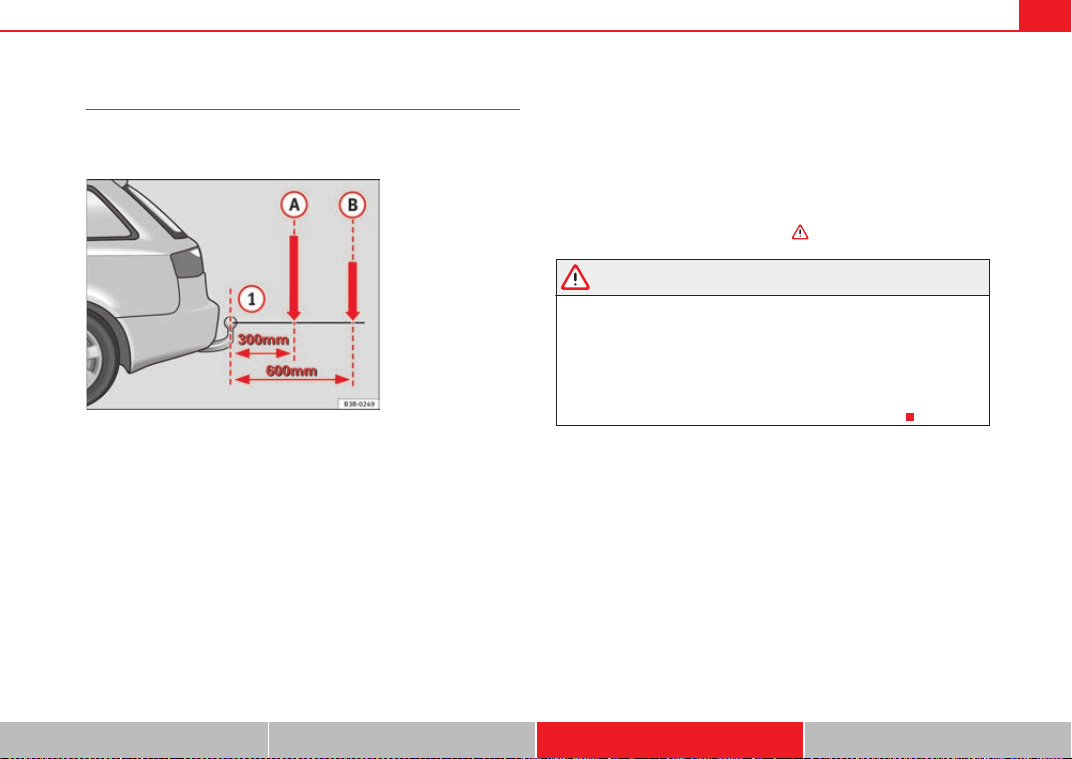
Trailer towing 205
Safety First Operating Instructions Practical Tips Technical Specifications
Equipment and accessories
Before mounting equipment and accessories (e.g. bicycle
rack) please observe the following notes.
The equipment/accessories mounted must not protrude more than 700 mm
from the ball joint .
The total weight (mounted equipment plus the load) must not exceed 75 kg.
The maximum load depends on where the centre of gravity lies.
The maximum weight decreases as the distance between the centre of gravity
and the ball joint increases.
The following limits apply:
If the distance is 300 mm, the total weight (incl. the equipment mounted)
must not exceed 75 kg.
If the distance is 600 mm, the total weight (incl. the equipment mounted)
must not exceed 35 kg.
Only bicycle racks for a maximum of three bicycles may be used.
Equipment and accessories mounted on the towing bracket
SEAT recommends that you only mount equipment (e.g. bicycle rack) on the
towing bracket which has been officially approved.. If you wish to attach other
equipment please make sure that it has been approved by the manufacturer
for use on the towing bracket. If you mount unsuitable equipment, this can
cause damage to the towing bracket. In an extreme case, damage to the
towing bracket could cause it to break ⇒ .
WARNING
• If you wish to mount equipment which has not been approved by SEAT,
please ensure that it is suitable for use on SEAT vehicles.
• The use of unsuitable accessories can result in severe damage to the
towing bracket, which could break while pulling a trailer. Risk of accident.
• Never use tools of any kind when fitting and removing the ball joint.
This would damage the locking device, no longer guaranteeing the correct
working order of the bracket. This could lead to an accident.
Fig. 161 Load distribu-
tion of equipment and
accessories
A
1
A
1
A
A
A
B
ExeoST_EN.book Seite 205 Freitag, 3. September 2010 11:41 11
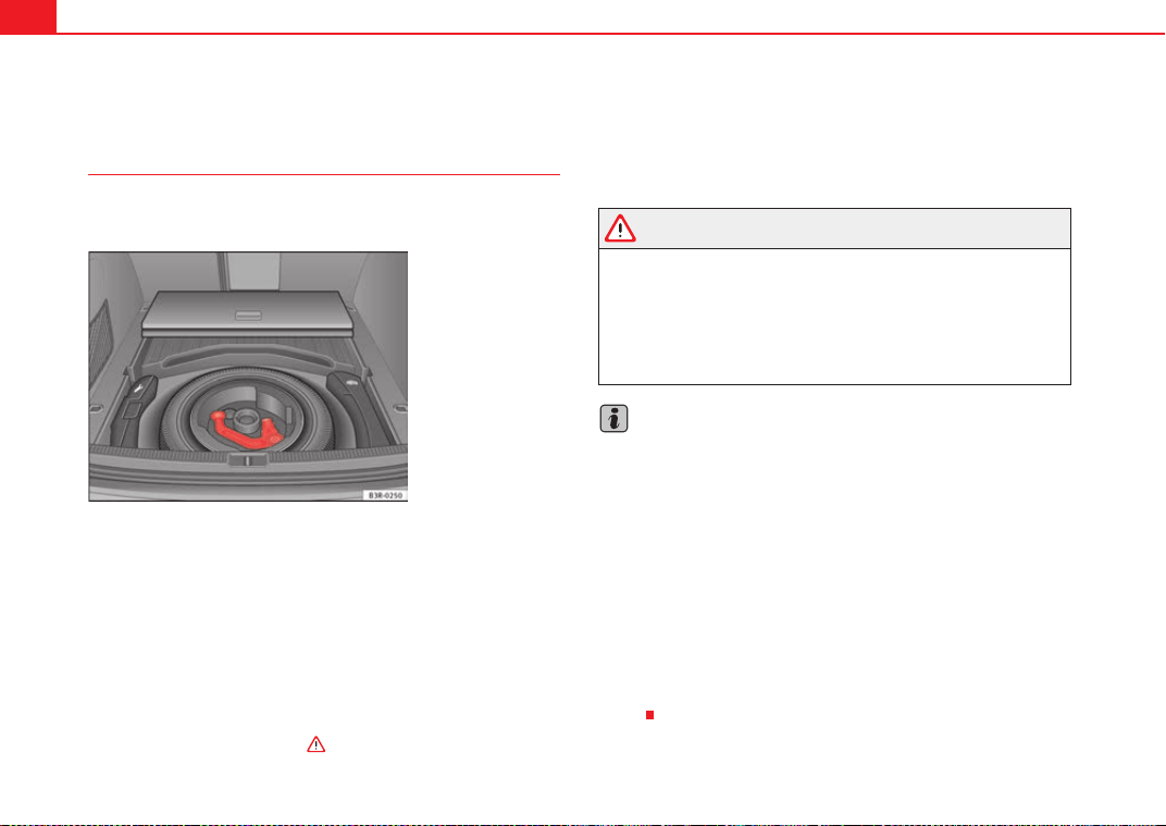
Trailer towing206
Removable towing bracket
Introduction
Special care is required when fitting and removing the towing
bracket.
The removable ball joint attachment for the towing bracket is stored under the
floor panel in the luggage compartment.
• Vehicles with a spare wheel ⇒ fig. 162.
The ball joint can be fitted and removed by hand.
Accessories mounted on the towing bracket
Please note that the ball joint attachment can be damaged by using unsuit-
able equipment that is mounted onto the towing bracket (e.g. bicycle rack).
Due to the material construction, such damage to the towing bracket dramat-
ically increases safety risks and in extreme cases could lead to breakage of
the towing bracket while towing ⇒ .
Therefore, before buying such equipment, ensure that it is suitable for
mounting onto the vehicle's towing bracket and that it is approved for this
purpose. To prevent damage to the ball joint from unsuitable equipment, we
recommend that equipment for the towing bracket be purchased through
your SEAT Dealer. Also see ⇒ page 223.
WARNING
• Only mount equipment on the towing bracket of your vehicle if you are
certain it will not damage the bracket. The use of unsuitable accessories
can result in severe damage to the towing bracket, which could break while
pulling a trailer. Risk of accident.
• Never use tools of any kind when fitting and removing the ball joint.
This would damage the locking device, no longer guaranteeing the correct
working order of the bracket. This could lead to an accident.
Note
• Do not attempt to modify or repair the ball joint or other towing bracket
components.
• Should you have any difficulties when using the towing bracket, or
suspect that it is not fitted properly, contact a qualified workshop.
• Before setting off, always check that the ball joint is secured properly
⇒ page 209.
• Never disengage the ball joint with the caravan / trailer still hitched or
with a bicycle rack or similar accessory still attached.
• It is advisable to remove the ball joint when you are not towing a trailer.
Make sure that the cover piece is properly fitted on the mounting fixture on
the vehicle.
• Remove the ball joint before washing the vehicle with pressurised steam
equipment. Make sure the cover piece is fitted correctly onto the mounting
fixture.
Fig. 162 Luggage
compartment: Spare
wheel with towing bracket
ExeoST_EN.book Seite 206 Freitag, 3. September 2010 11:41 11
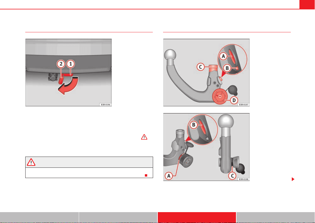
Trailer towing 207
Safety First Operating Instructions Practical Tips Technical Specifications
Fitting the ball joint (step 1)
– Remove the cover piece ⇒ fig. 163 on the mounting fixture
below the bumper as far as it will go. The cover piece is held
automatically in the open position.
– Make sure the mounting fixture is clean. If not, clean it ⇒ .
Cont ⇒ page 207, “Fitting the ball joint (step 2)”.
WARNING
It is important to keep the mounting fixture clean. Otherwise the ball joint
may fail to engage safely and securely. This could lead to an accident.
Fitting the ball joint (step 2)
Fig. 163 Rear bumper:
Open the cover piece
A
2
A
1
Fig. 164 Removable
towing bracket: Ball joint
Fig. 165 Removable
towing bracket: Ball joint
ExeoST_EN.book Seite 207 Freitag, 3. September 2010 11:41 11
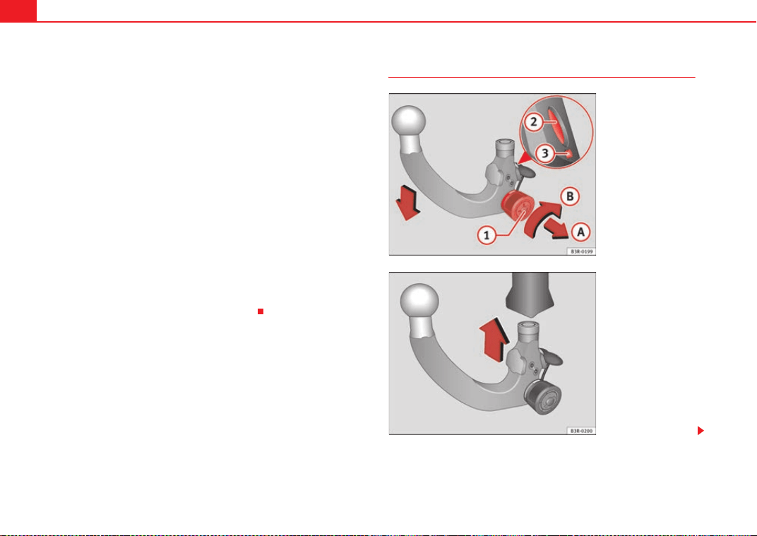
Trailer towing208
Make sure the ball joint is clean and undamaged
– Check the locking pin , release pin , shaft section and
knob ⇒ page 207, fig. 164 on the ball joint to make sure they
are clean and undamaged.
The spring mechanism inside the ball joint must be in the ready
position
– Check that the red marking ⇒ page 207, fig. 165 on the knob
is inside the black zone marked on the ball joint.
– Check that the locking pin is inside the holes in the shaft
section of the ball joint.
– Check that the knob protrudes visibly from the ball joint, so that
there is a clear gap between the knob and the ball joint.
The ball joint can only be installed if the internal spring mechanism is in the
ready position.
Cont ⇒ page 208, “Fitting the ball joint (step 3)”.
Fitting the ball joint (step 3)
A
A
A
B
A
C
A
D
A
A
A
B
A
C
Fig. 166 Removable
towing bracket: Setting
the spring mechanism to
the "ready" position
Fig. 167 Removable
towing bracket: Inserting
the ball joint
ExeoST_EN.book Seite 208 Freitag, 3. September 2010 11:41 11
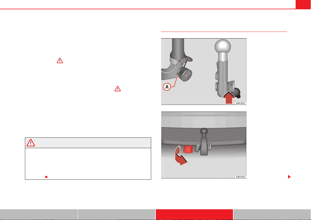
Trailer towing 209
Safety First Operating Instructions Practical Tips Technical Specifications
Setting the spring mechanism to the ready position (if required)
– Insert the key ⇒ page 208, fig. 166 in the lock on the knob
and turn it towards the red marking.
– Pull out the knob in direction , hold and turn in direction
until the locking pin engages and the release pin moves
out visibly ⇒ .
Inserting the ball joint
– With the spring mechanism in the ready position, insert the ball
joint into the mounting fixture and push it upwards ⇒ page 208,
fig. 167 in the direction indicated (arrow) ⇒ . It should lock
into position automatically. You should now clearly hear it click
into place.
– Lock the ball joint by turning the key to the green marking.
– Remove the key.
Cont ⇒ page 209, “Fitting the ball joint (step 4)”.
WARNING
• If it is not possible to set the spring mechanism to the ready position as
described above, do not use the ball joint. Please contact a qualified work-
shop.
• To avoid injury, keep your hands away from the knob or cover piece
when inserting the ball joint in the mounting fixture. Otherwise, you could
be injured.
Fitting the ball joint (step 4)
A
1
A
A
A
B
A
2
A
3
Fig. 168 Removable
towing bracket: Safety
check
Fig. 169 Rear bumper:
Pulling down the power
socket
ExeoST_EN.book Seite 209 Freitag, 3. September 2010 11:41 11
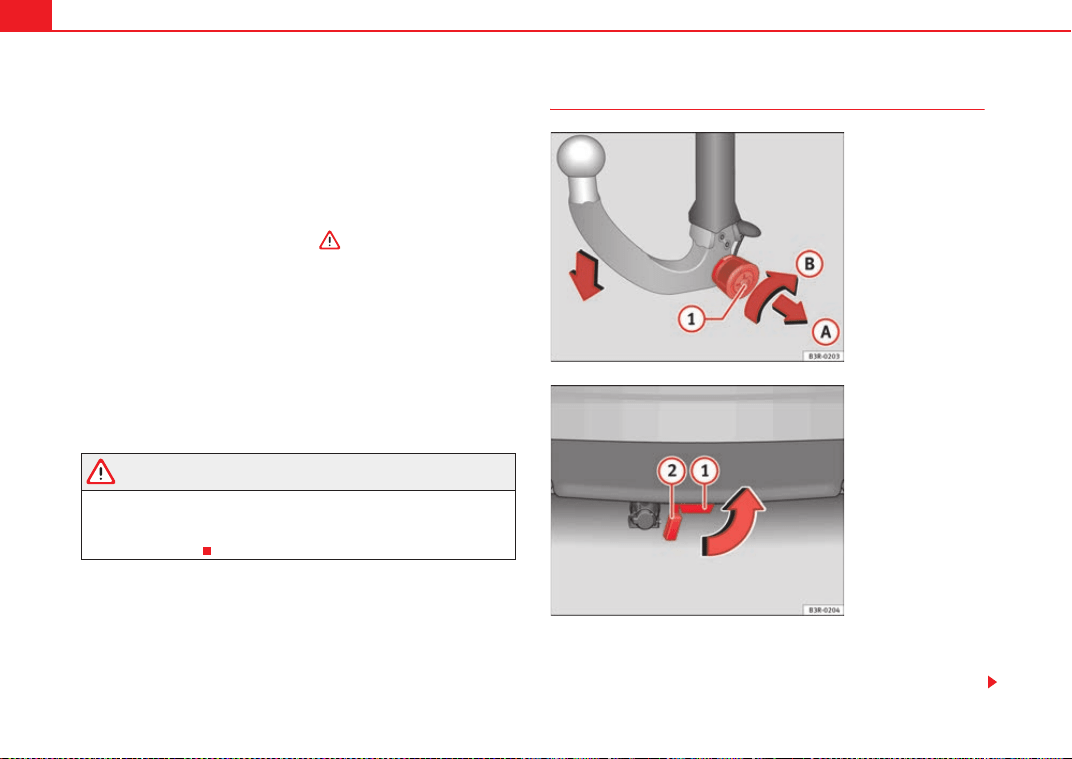
Trailer towing210
Safety check
– Check that the green marking ⇒ page 209, fig. 168 on the
knob is inside the black zone marked on the ball joint.
– Check that the knob is directly against the ball joint, so that there
is no gap between the knob and the ball joint -arrow-.
– Check that the ball joint is locked and the key is removed so that
the knob cannot be pulled out ⇒ .
– Check that the ball joint fits tightly in the mounting fixture (try
moving it about to check).
Towing socket
– To plug in the electrical connection for the trailer, pull down the
socket below the bumper ⇒ page 209, fig. 169.
If the safety check is not satisfactory, the ball joint must be fitted again prop-
erly.
WARNING
To avoid accidents, the ball joint must meet all the safety requirements
listed in the safety check. The towing bracket must not be used if any one
of these requirements is not met. If this is the case, you should contact a
qualified workshop.
Removing the ball joint
– Insert the key in the lock ⇒ fig. 170 on the knob.
– Unlock the ball joint by turning the key to the red marking.
A
A
Fig. 170 Removable
towing bracket: Removing
the ball joint
Fig. 171 Rear bumper:
fitting the cover piece
A
1
ExeoST_EN.book Seite 210 Freitag, 3. September 2010 11:41 11
Trailer towing 211
Safety First Operating Instructions Practical Tips Technical Specifications
– Take hold of the ball joint and pull out the knob in direction .
– Keep hold of the knob and turn it as far as it will go in direction
.
– Release the knob. The spring mechanism will remain in the ready
position ⇒ .
– Pull the ball joint down out of the mounting fixture
⇒ page 210, fig. 171. The cover piece will cover the mounting
fixture automatically .
– Put away the ball joint attachment under the floor panel in the
luggage compartment.
– Move the socket back up to its original position.
WARNING
• To avoid injury, keep your hands away from the locking pin and the
release pin when releasing the locking mechanism.
• Make sure that the cover piece is properly engaged on the mounting
fixture on the vehicle. Otherwise the ball joint may fail to engage securely
if dirt accumulates in the mounting fixture.
A
A
A
B
A
1
A
2
ExeoST_EN.book Seite 211 Freitag, 3. September 2010 11:41 11
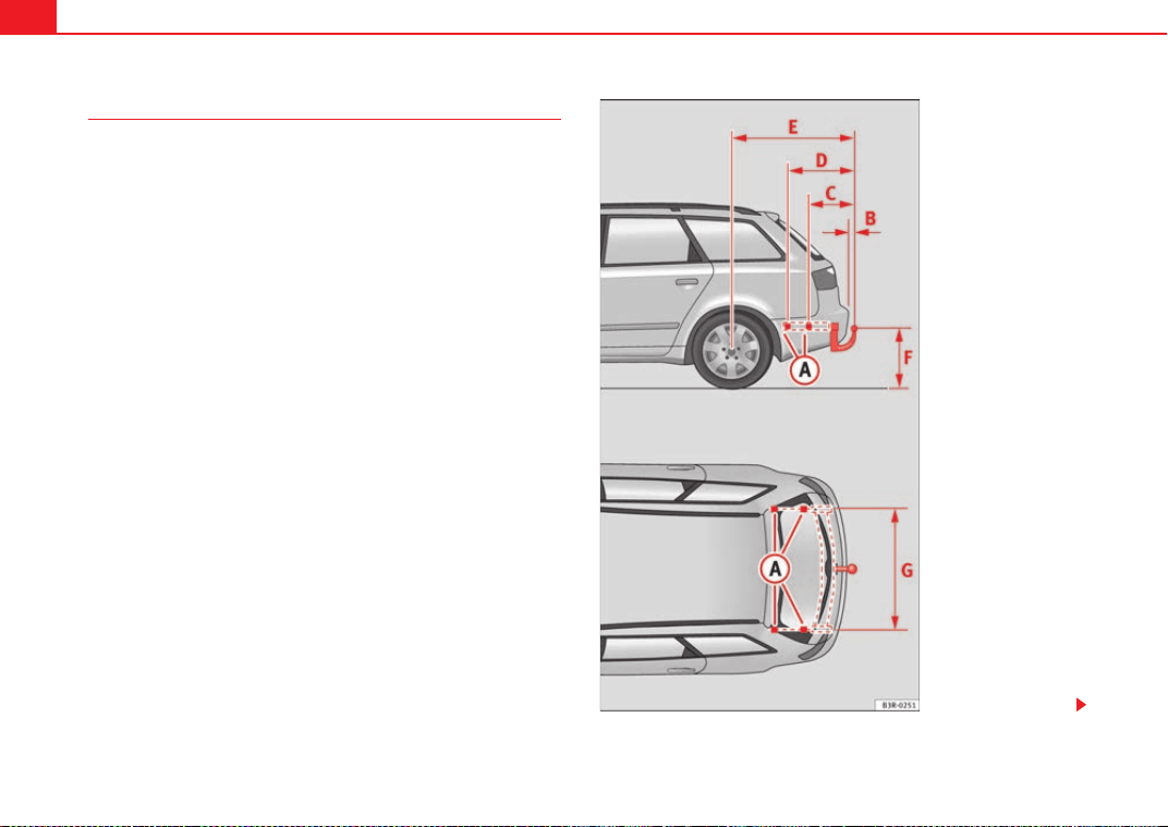
Trailer towing212
Fitting a towing bracket*
It is possible to fit a towing bracket to the rear of the vehicle.
Fig. 172 Attachment
points for towing bracket
ExeoST_EN.book Seite 212 Freitag, 3. September 2010 11:41 11
Trailer towing 213
Safety First Operating Instructions Practical Tips Technical Specifications
If a towing bracket is to be fitted after the vehicle is purchased, this must be
completed according to the instructions of the towing bracket manufacturer.
The attachment points for the towing bracket are on the lower part of the
vehicle.
The distance between the centre of the ball coupling and the ground should
never be lower than the indicated value, even with a fully loaded vehicle and
including the maximum drawbar load.
Elevation values for securing the towing bracket:
65 mm (minimum)
403
629 mm
1112 mm (vehicle with max. load)
from 350 to 420 mm (vehicle with max. load)
1000 mm
Fitting a towing bracket
• Driving with a trailer involves an extra effort for the vehicle. Therefore,
before fitting a towing bracket, please contact an Authorised Service Centre
to check whether your cooling system needs modification.
• The legal requirements in your country must be observed (e.g. the fitting
of a separate warning lamp).
• Certain vehicle components, e.g. the rear bumper, must be removed and
reinstalled. The towing bracket securing bolts must be tightened using a
torque wrench, and a power socket must be connected to the vehicle's elec-
trical system. This requires specialised knowledge and tools.
• Figures in the illustration show the elevation value and the attachment
points which must be considered if you are retrofitting a towing bracket.
WARNING
The towing brackets should be fitted at a specialised workshop.
• If the towing bracket is incorrectly installed, there is serious danger of
accident.
• For your own safety, please observe the instructions provided by the
manufacturer of the towing bracket.
Caution
• If the power socket is incorrectly installed, this could cause damage to the
vehicle's electrical system.
Note
For the Sport finish, fitting a trailer bracket is not recommended due to the
design of the bumpers.
A
A
A
B
A
C
A
D
A
E
A
F
A
G
WARNING (continued)
ExeoST_EN.book Seite 213 Freitag, 3. September 2010 11:41 11
Vehicle maintenance and cleaning214
Vehicle maintenance and cleaning
General notes
Regular washing and care help maintain the value of your
vehicle.
Vehicle maintenance
Regular care and washing help to maintain the value of the vehicle. This may
also be one of the requirements for acknowledging warranty claims in the
event of bodywork corrosion or paint defects.
The best way to protect your vehicle against the harmful effects of the envi-
ronment is through correct maintenance and frequent washing. The longer
substances such as insect remains, bird droppings, resinous tree sap, road
dirt, industrial deposits, tar, soot or road salt and other aggressive materials
remain on the vehicle, the more damage they do to the paintwork. High
temperatures (for instance in strong sunlight) further intensify the corrosive
effect.
After winter, a period when salt is put on the roads, it is important to have the
underside of the vehicle washed thoroughly.
Products for vehicle maintenance
Car care products are available in your Authorised Service Centre. Keep the
product instructions until you have used them up.
WARNING
• Car care products can be toxic. Because of this, they must always be
kept closed in their original container. Keep them out of the reach of chil-
dren. Failure to comply could result in poisoning.
• Always read and observe the instructions and warnings on the package
before using vehicle care products. Improper use could cause health prob-
lems or damage the vehicle. The use of certain products may produce
noxious vapours; they should be used in well ventilated areas.
• Never use fuel, turpentine, engine oil, nail varnish remover or other
volatile fluids. These are toxic and highly flammable. Risk of fire and explo-
sion.
• Before washing your vehicle, or carrying out any maintenance, switch
the engine off, apply the handbrake firmly and remove the key from the
ignition.
Caution
Never attempt to remove dirt, mud or dust if the surface of the vehicle is dry.
Never use a dry cloth or sponge for cleaning purposes. This could damage the
paintwork or the windows of your vehicle. Soak dirt, mud or dust with plenty
of water.
For the sake of the environment
• When purchasing products for your vehicle maintenance, select the ones
which are not harmful to the environment.
• The waste from car care products should not be disposed of with ordinary
household waste. Observe the disposal information on the package.
WARNING (continued)
ExeoST_EN.book Seite 214 Freitag, 3. September 2010 11:41 11
Vehicle maintenance and cleaning 215
Safety First Operating Instructions Practical Tips Technical Specifications
Vehicle exterior maintenance
Automatic car wash tunnel
The vehicle can normally be washed without problem in an
automatic car wash.
The vehicle paintwork is so durable that the vehicle can normally be washed
without problems in an automatic car wash tunnel. However, the paintwork
wear depends to a large extent on the kind of the car wash tunnel, the
brushes used, its water filtering and the type of cleaning and preservative
products.
Before going through a vehicle wash, be sure to take the usual precautions
such as closing the windows and sunroof.
If the vehicle has special accessories such as spoilers or a roof rack or two-
way radio aerial, etc., it is advisable to consult the car wash tunnel operator.
After washing, the brakes could take some time to respond as the brake discs
and pads could be wet, or even frozen in winter. Dry the brakes by braking
several times.
WARNING
Water, ice and salt on the brakes can reduce braking efficiency. Risk of
accident.
Washing by hand
Vehicle washing
– First soften the dirt with plenty of water and rinse it off.
– Clean your vehicle from top to bottom with a soft sponge, a glove
or a brush. Use very light pressure.
– Rinse the sponge or glove often with clean water.
– Special car shampoo should only be used for very stubborn dirt.
– Leave the wheels, sill panels etc. until last, using a different
sponge or glove.
– Rinse the vehicle thoroughly with water.
– Dry the vehicle surface gently with a chamois leather.
–In cold temperature, dry the rubber seals and their surfaces to
prevent them from freezing. Apply silicone spray to the rubber
seals.
After washing
– After washing, avoid sudden and sharp braking. Dry the brakes
by braking several times ⇒ page 197, “Braking capacity and
braking distance”.
WARNING
• Wash your vehicle with the ignition switched off.
• Protect your hands and arms from cuts on sharp metal edges when
cleaning the underbody, the inside of the wheel housings etc. Risk of
injury.
• Water, ice and salt on the brakes can reduce braking efficiency. Risk of
accident.
ExeoST_EN.book Seite 215 Freitag, 3. September 2010 11:41 11
Vehicle maintenance and cleaning216
Caution
• Never remove dirt, mud or dust if the vehicle surface is dry. Never use a
dry cloth or sponge for cleaning purposes. This could scratch the paintwork
or glass on your vehicle.
• Washing the vehicle in low temperatures: when washing the vehicle with
a hose, do not direct water into the lock cylinders or the gaps around the
doors, tailgate, or sunroof. Risk of freezing.
For the sake of the environment
To protect environment, the vehicle should be washed only in specially
provided wash bays. This prevents toxic, oil-laden waste water entering the
sewerage system. In some places, washing vehicles outside wash bays is
prohibited.
Note
Do not wash the vehicle in direct sunlight.
Washing the vehicle with a high pressure cleaner
Be particularly careful when using a high pressure cleaner!
– Always observe the instructions for the high-pressure cleaner,
particularly those concerning the pressure and the spraying
distance.
– Increase the spraying distance for soft materials and painted
bumpers.
– Do not use a high pressure cleaner to remove ice or snow from
windows ⇒ page 217.
– Never use concentrated jet nozzles (“rotating jets”) ⇒ .
– After washing, avoid sudden and sharp braking. Dry the brakes
by braking several times ⇒ page 197.
WARNING
• Never wash tyres with a concentrated jet (“rotating nozzle”). Even at
large spraying distances and short cleaning times, visible and invisible
damage can occur to the tyres. This may cause an accident.
• Water, ice and salt on the brakes can reduce braking efficiency. Risk of
accident.
Caution
• Do not use water hotter than 60 °C. This could damage the vehicle.
• To avoid damage to the vehicle, keep a sufficient distance from sensitive
materials such as flexible hoses, plastic, soundproofing material, etc. This is
also important for bumpers painted in the colour of the bodywork. The closer
the nozzle is to the surface, the greater the wear on the material.
Vehicle paint maintenance
Regular waxing protects the paintwork.
You need to apply wax to your vehicle if water does not form small drops and
run off the paintwork when it is clean.
Good quality hard wax products are available at your Authorised Service
Centre.
ExeoST_EN.book Seite 216 Freitag, 3. September 2010 11:41 11
Vehicle maintenance and cleaning 217
Safety First Operating Instructions Practical Tips Technical Specifications
Regular wax applications help to protect the paintwork from environmental
contaminants ⇒ page 214. It is also effective in protecting against minor
scratches.
Even if a wax solution is used regularly in the vehicle washing tunnel, it is
advisable to protect the paint with a hard wax coating at least twice a year.
Polishing the paintwork
Polishing brings back gloss to the paintwork.
Polishing is only necessary if the paint has lost its shine, and the gloss cannot
be brought back by applying wax. Polishing products can be purchased in
your Authorised Service Centre.
The vehicle must be waxed after polishing if the polish used does not contain
wax compounds to seal the paint ⇒ page 216, “Vehicle paint maintenance”.
Caution
To prevent damage to the paintwork:
• Do not use polishes and hard wax on painted parts with a matte finish or
on plastic parts.
• Do not polish your vehicle in a sandy or dusty environment.
Caring for plastic parts
Solvents damage plastic parts.
If normal washing fails to clean plastic parts, clean them with approved
solvent-free plastic cleaning and care products.
Caution
• The use of liquid air freshener directly over the air vents of the vehicle may
damage the plastic parts if the liquid is accidentally spilled.
• Cleaning products which contain solvents will damage the material.
Cleaning windows and exterior mirrors
Cleaning windows
– Moisten the windows with commercially available, alcohol based
glass cleaner.
– Dry the windows with a clean chamois leather or a lint-free cloth.
Removing snow
– Use a small brush to remove snow from the windows and mirrors.
Removing ice
–Use a de-icer spray.
Use a clean cloth or chamois leather to dry the windows. The chamois
leathers used on painted surfaces are not suitable to clean windows because
they are soiled with wax deposits which could smear the windows.
If possible, use a de-icing spray to remove ice. If you use an ice scraper, push
it in one direction only without swinging it.
Use window cleaner or a silicone remover to clean rubber, oil, grease and sili-
cone deposits off.
Wax deposits can be removed with a special cleaner available in your Author-
ised Service Centre. Wax deposits on the windscreen could cause the wiper
blades to judder. Adding a window cleaner that dissolves wax to the wind-
ExeoST_EN.book Seite 217 Freitag, 3. September 2010 11:41 11
Vehicle maintenance and cleaning218
screen washer fluid prevents wiper blades from juddering, but wax deposits
are not removed.
Caution
• Never use warm or hot water to remove snow and ice from windows and
mirrors. This could cause the glass to crack!
• The heating element for the rear window is located on the inner side of the
window. To prevent damage, do not put stickers on the heating elements
inside the window.
Cleaning windscreen wiper blades
Clean wiper blades are essential to provide clear vision.
1. Use a soft cloth to remove dust and dirt from the windscreen
wiper blades.
2. Use window cleaner to clean the windscreen wiper blades. Use a
sponge or a cloth to remove stubborn dirt.
Rubber seals maintenance
If rubber seals are well looked after, they will not freeze so
quickly.
1. Use a soft cloth to remove dust and dirt from the rubber seals.
2. Apply a specialist care product to the rubber seals.
The rubber strips on the doors, windows, bonnet and tailgate will remain
pliable and last longer if they are treated with a suitable care product (for
example silicone spray).
Caring for rubber seals will also prevent premature ageing and leaks. The
doors will be easier to open. If rubber seals are well looked after, they will not
freeze so quickly in winter.
Door lock cylinders
The door lock cylinders can freeze up in winter.
To de-ice the lock cylinders you should only use spray with lubricating and
anti-corrosive properties.
Cleaning chrome parts
1. Clean chrome parts with a damp cloth.
2. Polish chrome parts with a soft, dry cloth.
If this does not provide satisfying results, use a specialist chrome cleaning
product. Chrome cleaning products will remove stains from the surface.
Caution
To prevent scratching chrome surfaces:
• Never use an abrasive cleaning product on chrome.
• Do not clean or polish chrome parts in a sandy or dusty environment.
ExeoST_EN.book Seite 218 Freitag, 3. September 2010 11:41 11
Vehicle maintenance and cleaning 219
Safety First Operating Instructions Practical Tips Technical Specifications
Steel wheel rims
– Clean steel wheel rims regularly using a separate sponge.
Use an industrial cleaner to remove brake dust. Any damage to the paint on
steel wheel rims should be repaired before starting to rust.
WARNING
• Never wash tyres with a cylindrical jet. Even at large spraying distances
and short cleaning times, visible and invisible damage can occur to the
tyres. This may cause an accident.
• Water, ice and salt on the brakes can reduce braking efficiency. Risk of
accident. Directly after washing, avoid sudden and sharp braking. Dry the
brakes by braking several times ⇒ page 197.
Alloy wheel rims
Every two weeks
– Wash salt and brake dust from alloy wheels.
– Use an acid free detergent to clean the wheel rims.
Every three months
– Apply a hard wax compound to the wheels.
Alloy wheels require regular attention to preserve their appearance. If road
salt and brake dust are not often removed, the aluminium finish will be
impaired.
Always use an acid-free detergent for alloy wheel rims.
Car polish or other abrasive agents should not be used. If the protective
coating is damaged, e.g. by flying stones, the damaged area should be
repaired immediately.
WARNING
• Never wash tyres with a cylindrical jet. Even at large spraying distances
and short cleaning times, visible and invisible damage can occur to the
tyres. This may cause an accident.
• Water, ice and salt on the brakes can reduce braking efficiency. Risk of
accident. Directly after washing, avoid sudden and sharp braking. Dry the
brakes by braking several times ⇒ page 197.
Underbody protection
The vehicle underbody is coated to protect it from chemical
and mechanical damage.
The protective coating can be damaged when driving. We recommend you to
check the protective coating under the body and on the running gear, and
reinstated if necessary, before and after the winter season.
We recommend you to go to your Authorised Service Centre to carry out repair
work and additional anti-corrosion work.
WARNING
Do not apply underseal or anti-corrosion coatings to the exhaust pipes,
catalytic converter or the heat shields on the exhaust system. The heat of
the exhaust system or the engine could cause them to ignite. Risk of fire.
ExeoST_EN.book Seite 219 Freitag, 3. September 2010 11:41 11
Vehicle maintenance and cleaning220
Cleaning the engine compartment
Take special care when cleaning the engine compartment.
Anti-corrosion treatment
The engine compartment and the surface of the power unit are given anti-
corrosion treatment at the factory.
Good corrosion protection is particularly important in winter when the vehicle
is frequently driven on salted roads. To prevent the salt corroding the vehicle,
the entire engine compartment should be thoroughly cleaned before and
after winter.
Your Authorised Service Centre has got the necessary equipment to provide
the correct cleaning and preserving products. For this reason, we recommend
having this work performed by them.
The anti-corrosion protection is usually removed if the engine compartment
is cleaned with grease removing solutions, or if you have the engine cleaned.
On commissioning this work, ensure that all surfaces, seams, joints and
components in the engine compartment are given anti-corrosion treatment.
WARNING
• When working in the engine compartment, always observe the safety
warnings ⇒ page 229.
• Before opening the bonnet, switch the engine off, apply the handbrake
firmly and always remove the key from the ignition.
• Allow the engine to cool before you clean the engine compartment.
• Do not clean the vehicle underbody, wheel arches or wheel trims
without protecting your hands and arms. You may cut yourself on sharp-
edged metal parts. Failure to comply could result in injury.
• Moisture, ice and salt on the brakes may affect braking efficiency. Risk
of accident. Directly after washing, avoid sudden and sharp braking.
• Never touch the radiator fan. It is temperature-controlled and could
start automatically, even when the key is removed from the ignition!
For the sake of the environment
Fuel, grease and oil deposits could be removed when the engine is washed.
The polluted water must be cleaned in an oil separator. For this reason,
engine washing should be carried out only by a qualified workshop or a petrol
station.
Vehicle interior maintenance
Plastic parts and dash panel cleaning
– Use a clean, damp cloth to clean plastic parts and the dash
panel.
– If this does not provide satisfactory results, use a special
solvent-free plastic cleaning product.
WARNING
Never clean the dash panel and the airbag module surface with cleaners
containing solvents. Solvents cause the surface to become porous. If the
airbag triggered, plastic parts could become detached and cause injuries.
Caution
Cleaning products which contain solvents will damage the material.
WARNING (continued)
ExeoST_EN.book Seite 220 Freitag, 3. September 2010 11:41 11
Vehicle maintenance and cleaning 221
Safety First Operating Instructions Practical Tips Technical Specifications
Wooden trim cleaning*
– Clean the wooden trim with a water-moistened clean cloth.
– If this does not provide satisfactory results, use a gentle soap
solution.
Caution
Cleaning products which contain solvents will damage the material.
Cloth seat covers and fabric trim cleaning
Cloth seat covers and fabric trim on the doors, headlining etc. can be cleaned
with a special interior cleaner or with dry foam and a soft brush.
Leather cleaning*
Normal cleaning
– Moisten a cotton or woollen cloth with water and wipe over the
leather surfaces.
Cleaning stubborn stains
– More stubborn dirt can be removed using a mild soap solution
(pure liquid soap; two tablespoons diluted in one litre of water)
and a cloth.
– Do not let the water soak through the leather or soak into the
seams.
– Then wipe off with a soft, dry cloth.
Leather maintenance
– The leather should be treated twice a year with a special leather-
care product, available in your Authorised Service Centre.
– Apply these products very sparingly.
– Then wipe off with a soft, dry cloth.
SEAT does everything possible to preserve the genuine qualities of this
natural product. Due to the natural properties of the specially selected hides
employed, the finished leather has a certain sensitivity to grease and dirt, etc.
so a degree of care is required in everyday use and when looking after the
leather.
Dust and grit in the pores and seams can scratch and damage the surface. If
the vehicle is under solar radiation for long periods, the leather should be
protected to prevent it from fading. However, slight colour variations in high-
quality natural leather are normal.
Caution
• Do not use solvents, wax polish, shoe cream, spot removers or similar
products on leather.
• To avoid damage, stubborn stains should be removed by a qualified
workshop.
Seat belt cleaning
A dirty belt may not work properly.
Check all seat belts regularly and keep them clean.
ExeoST_EN.book Seite 221 Freitag, 3. September 2010 11:41 11
Vehicle maintenance and cleaning222
Seat belt cleaning
– Pull the dirty seat belt right out and unroll it.
– Clean dirty seat belts with a gentle soap solution.
–Allow it to dry.
– Do not roll the seat belt up until it is dry.
If large stains form on the belts, it will not retract correctly into the automatic
belt retractor.
WARNING
• Do not use chemical cleaning agents on the seat belts, as this can
impair the strength of the webbing. Ensure that belts do not come into
contact with corrosive fluids.
• Check the condition of the seat belts at regular intervals. If you notice
that the belt webbing, fittings, retractor mechanism or buckle of any of the
belts is damaged, the belt must be replaced by a specialist workshop.
• Do not attempt to repair a damaged seat belt yourself. The seat belts
must not be removed or modified in any way.
Caution
After cleaning, allow seat belts to dry completely before rolling them up.
Otherwise, the belt retractors could become damaged.
ExeoST_EN.book Seite 222 Freitag, 3. September 2010 11:41 11
Accessories, parts replacement and modifications 223
Safety First Operating Instructions Practical Tips Technical Specifications
Accessories, parts replacement and modifications
Accessories and spare parts
Always consult an Authorised Service Centre before
purchasing accessories and parts.
Your vehicle is designed to offer a high standard of active and passive safety.
Before purchasing accessories and parts, and before making technical
changes to your vehicle, we recommend you to consult your Authorised
Service Centre.
SEAT dealerships will be happy to provide you with the latest information
about the use, legal requirements and recommendations from the manufac-
turer regarding accessories and parts.
We recommend you use only SEAT Approved Accessories
®
and SEAT
Approved Spare Parts
®
. This way, SEAT can guarantee that the product in
question is suitable, reliable and safe. SEAT Authorised Service Centres have
the necessary experience and facilities to ensure that parts are correctly and
professionally installed.
Despite a continuous observation of the market, SEAT is not able to assess
the reliability, safety and suitability of those parts SEAT has not approved. For
this reason, SEAT cannot assume responsibility for any non-genuine parts
used, even if these parts have been approved by an official testing agency or
are covered by an official approval certificate.
Any equipment subsequently installed which has a direct effect on the
driver's control of the vehicle (e.g. cruise control system or electronically-
controlled suspension) must be approved by SEAT and bear the e mark (the
European Union's authorisation symbol).
Any additional electrical components that do not affect the control of the
vehicle itself (e.g. refrigerator box, laptop, ventilator fan, etc.), must bear the
CE mark (European Union manufacturer conformity declaration).
WARNING
Accessories, for example telephone holders or cup holders, should never
be fitted on the covers, or within the working range, of the airbags. Other-
wise, there is a danger of injury if the airbag is triggered in an accident.
Technical modifications
Modifications must always be carried out according to our
specifications.
Unauthorised modifications to the electronic components or software in the
vehicle may cause malfunctions. Due to the way the electronic components
are linked together in networks, other indirect systems may be affected by the
faults. This can seriously impair safety, lead to excessive wear of compo-
nents, and also invalidate your vehicle registration documents.
SEAT Authorised Service Centres cannot be held liable for any damage
caused by modifications and/or work incorrectly performed.
For this reason, we recommend that all work should be performed by an
Authorised Service Centre using Genuine SEAT
®
approved parts and acces-
sories.
ExeoST_EN.book Seite 223 Freitag, 3. September 2010 11:41 11
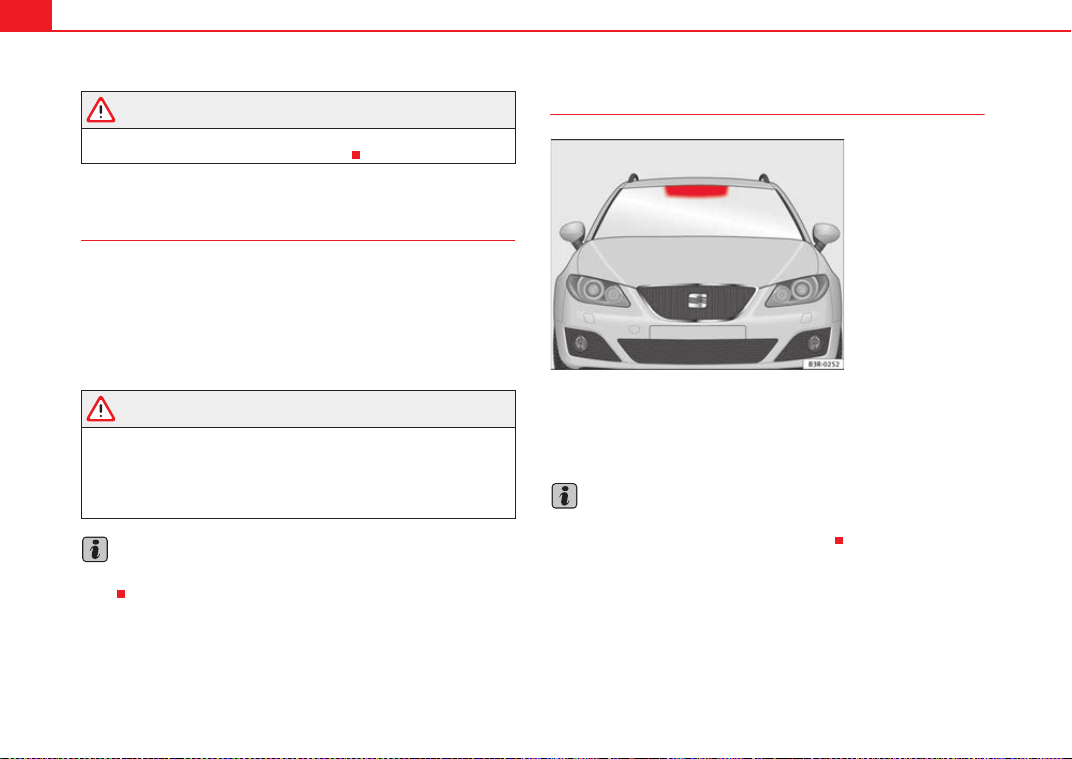
Accessories, parts replacement and modifications224
WARNING
Incorrectly performed modifications or other kind of work on your vehicle
can lead to malfunctions and cause accidents.
Mobile phones and two-way radios
First consult your Authorised Service Centre if you wish to use a mobile tele-
phone or a two-way radio with a transmitting power output in excess of
10 watts. Here you will receive information concerning the technical possibil-
ities for retrofitting this equipment.
Mobile telephones and two-way radios should be only fitted by a specialised
workshop, for example an Authorised Service Centre.
WARNING
• Always concentrate primarily on driving. If you are distracted while
driving you could have an accident.
• Never attach the telephone mountings to the surfaces covering the
airbag units or within the range of the airbags. There is a high danger of
injury if the airbag is triggered.
Note
Please observe the operating instructions of your mobile telephone / two-way
radio.
Athermic windscreen*
Vehicles with an athermic windscreen have an area without athermic treat-
ment above the rear view mirror⇒ fig. 173. This area has been designed for
the operating of electronic components of fitted devices (e.g. electronic toll
collection system).
Note
The customer should ensure that the electronic toll collection system is fitted
in the correct area to make sure it works correctly.
Fig. 173 Location of the
electronic toll collection
system
ExeoST_EN.book Seite 224 Freitag, 3. September 2010 11:41 11
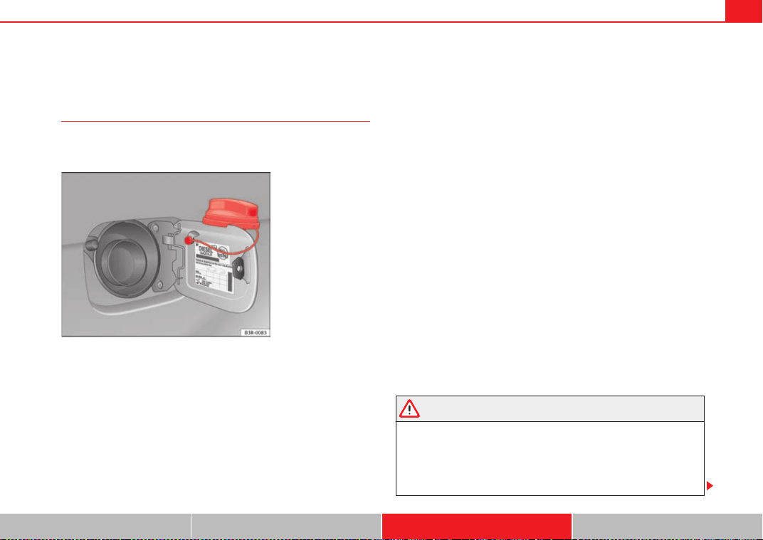
Checking and refilling levels 225
Safety First Operating Instructions Practical Tips Technical Specifications
Checking and refilling levels
Refuelling
The tank flap is released manually. The tank holds approxi-
mately 70 litres.
The flap that covers the tank cap is unlocked and locked automati-
cally by the central locking.
Unscrewing the tank cap
– Press the right side of the flap to open it.
– Unscrew the fuel tank cap anti-clockwise.
– Hook the cap onto the support fitted to the open tank flap
⇒ fig. 174.
Closing the tank cap
– Screw the tank cap clockwise into the filler opening until it you
hear it click into position.
– Close the tank flap.
The tank flap is at the rear of the vehicle on the right.
If the automatic filler nozzle is operated correctly, it will switch itself off as
soon as the tank is “full”. Never attempt to fill beyond this point, as this will
fill the expansion chamber. Fuel may leak out if ambient conditions are warm.
The correct fuel grade for your vehicle is given on a sticker on the inside of the
fuel tank flap. Here you will find further information on fuel.
Releasing the fuel tank flap manually*
If the central locking system fails, the fuel tank flap can be opened manually
as follows:
• Open the tailgate
• Remove the cover from the right side trim in the luggage compartment.
• Insert a hand and pull the locking device back
• Open the cap and take out the plug.
WARNING
• Fuel is highly flammable and can cause serious burns and other inju-
ries.
− Never smoke or use an open flame when filling the fuel tank of the
vehicle, or a spare fuel canister, with fuel. This is an explosion hazard.
− Follow legal requirements for the use of spare fuel canisters.
Fig. 174 Fuel tank flap
with tank cap attached
ExeoST_EN.book Seite 225 Freitag, 3. September 2010 11:41 11
Checking and refilling levels226
− For safety reasons we do not recommend carrying a spare fuel
canister in the vehicle. The canister could be damaged in an accident
and leak.
• If, in exceptional circumstances, you have to carry a spare fuel canister,
please observe the following points:
− Never fill the spare fuel canister inside the vehicle or on it. An elec-
trostatic charge could build up during filling, causing the fuel fumes to
ignite. This could cause an explosion. Always place the canister on the
ground to fill it.
− Insert the fuel nozzle into the mouth of the canister as far as
possible.
− If the spare fuel canister is made of metal, the filling nozzle must be
in contact with the canister during filling. This helps prevent an electro-
static charge building up.
− Never spill fuel in the vehicle or in the luggage compartment. Fuel
vapours are explosive. Danger of death.
Caution
• Fuel spills should be removed from the paintwork immediately.
• Never run the tank completely dry. An irregular fuel supply could cause
misfiring. As a result, unburnt fuel could enter the catalytic converter and
cause damage.
• When filling the fuel tank after having run it completely dry on a vehicle
with a diesel engine the ignition must be switched on for at least 30 seconds
without starting the engine. When you then start the engine it may take
longer than normal (up to one minute) for the engine to start firing. This is due
to the fact that the fuel system has to purge itself of air before starting.
For the sake of the environment
Do not try to put in more fuel after the automatic filler nozzle has switched off;
this may cause the fuel to overflow if it becomes warm.
Petrol
Petrol types
The recommended fuel types are listed on a sticker inside the
fuel tank flap.
Only unleaded petrol conforming to standard DIN EN 228 may be used for
vehicles with catalytic converters (EN = “European Standard”).
Fuel types are differentiated by the octane rating, e.g: 91, 95, 98 RON (RON
= “Research Octane Number”, unit for determining the knock resistance of
petrol). You may use petrol with a higher octane number than the one recom-
mended for your engine. However, this has no advantage in terms of fuel
consumption and engine power.
The correct fuel type for your vehicle is given in the technical table for the
engine, in the Technical Specifications section.
Caution
• Petrol with standard EN 228 may be mixed with small quantities of
ethanol. However, the bioethanol fuels available at commercial establish-
ments with reference E50 or E85, which contain a high percentage of ethanol,
may not be used, as they will damage the fuel system.
• Even one tankful of leaded fuel would permanently impair the efficiency
of the catalytic converter.
WARNING (continued)
ExeoST_EN.book Seite 226 Freitag, 3. September 2010 11:41 11
Checking and refilling levels 227
Safety First Operating Instructions Practical Tips Technical Specifications
• High engine speed and full throttle can damage the engine when using
petrol with an octane rating lower than the correct grade for the engine.
For the sake of the environment
Just one full tank of leaded fuel would seriously impair the efficiency of the
catalytic converter.
Petrol additives
Petrol additives improve the quality of the petrol.
The quality of the petrol influences the performance, power and life of the
engine. For this reason, you should use good quality petrol containing addi-
tives. These additives will help to prevent corrosion, keep the fuel system
clean and prevent deposits from building up in the engine.
If good quality petrol with additives is not available or engine problems occur,
the required additives must be added during refuelling.
Diesel
Diesel*
Diesel fuel must conform to DIN EN 590 (EN = “European Standard”). It must
have a cetane number (CN) of at least 51. The cetane number indicates the
ignition quality of the diesel fuel.
Notes on refuelling ⇒ page 225.
Biodiesel*
Caution
• Your vehicle is not designed to use biodiesel fuel. Never, under any
circumstances refuel with biodiesel. The use of biodiesel fuel could damage
the engine and the fuel system. The addition of biodiesel to diesel fuel by the
diesel manufacturer in accordance with standard EN 590 or DIN 51628 is
authorised and will not cause damage to the engine or the fuel system.
• The diesel engine has been designed to be used exclusively with diesel
fuel conforming to standard EN 590. Never refuel or use petrol, kerosene, fuel
oil or any other type of fuel. If you accidentally fill up the vehicle with the
wrong type of fuel, do not start the engine. Seek assistance from specialised
personnel. The composition of these fuels may severely damage the fuel
system and the engine.
Winter driving
Diesel can thicken in winter.
Winter-grade diesel
When using summer-grade diesel fuel, difficulties may be experienced at
sub-zero temperatures because the fuel thickens due to wax separation.
Therefore, winter-grade diesel fuel is available in some countries during the
cold months. It can be used at temperatures as low as -22 °C.
In countries with different climatic conditions the diesel fuel generally sold
has different temperature characteristics. Check with an Authorised Service
Centre or filling stations in the country concerned regarding the type of diesel
fuels available.
ExeoST_EN.book Seite 227 Freitag, 3. September 2010 11:41 11
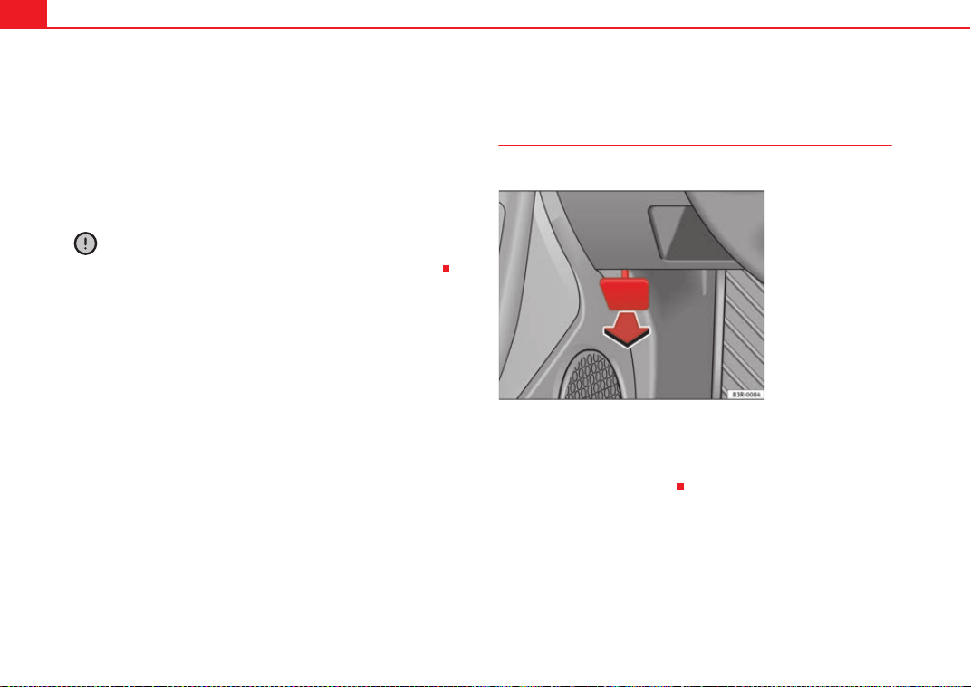
Checking and refilling levels228
Filter pre-heater
Your vehicle is fitted with a fuel filter glow plug system, making it well
equipped for operation in winter. This ensures that the fuel system remains
operational to approx. -24 °C, provided you use winter-grade diesel which is
safe to -15 °C.
However, if the fuel has waxed to such an extent that the engine will not start
at temperatures of under -24 °C, simply place the vehicle in a warm place for
a while.
Caution
Do not mix fuel additives (thinners or similar products) with diesel fuel.
Bonnet
Releasing the bonnet
The bonnet is released from inside the vehicle.
– To release the bonnet, pull the lever under the dash panel
⇒ fig. 175 in the direction indicated (arrow).
The bonnet springs out of its lock.
Fig. 175 Detail of foot-
well area on driver side:
lever for unlocking the
bonnet.
ExeoST_EN.book Seite 228 Freitag, 3. September 2010 11:41 11
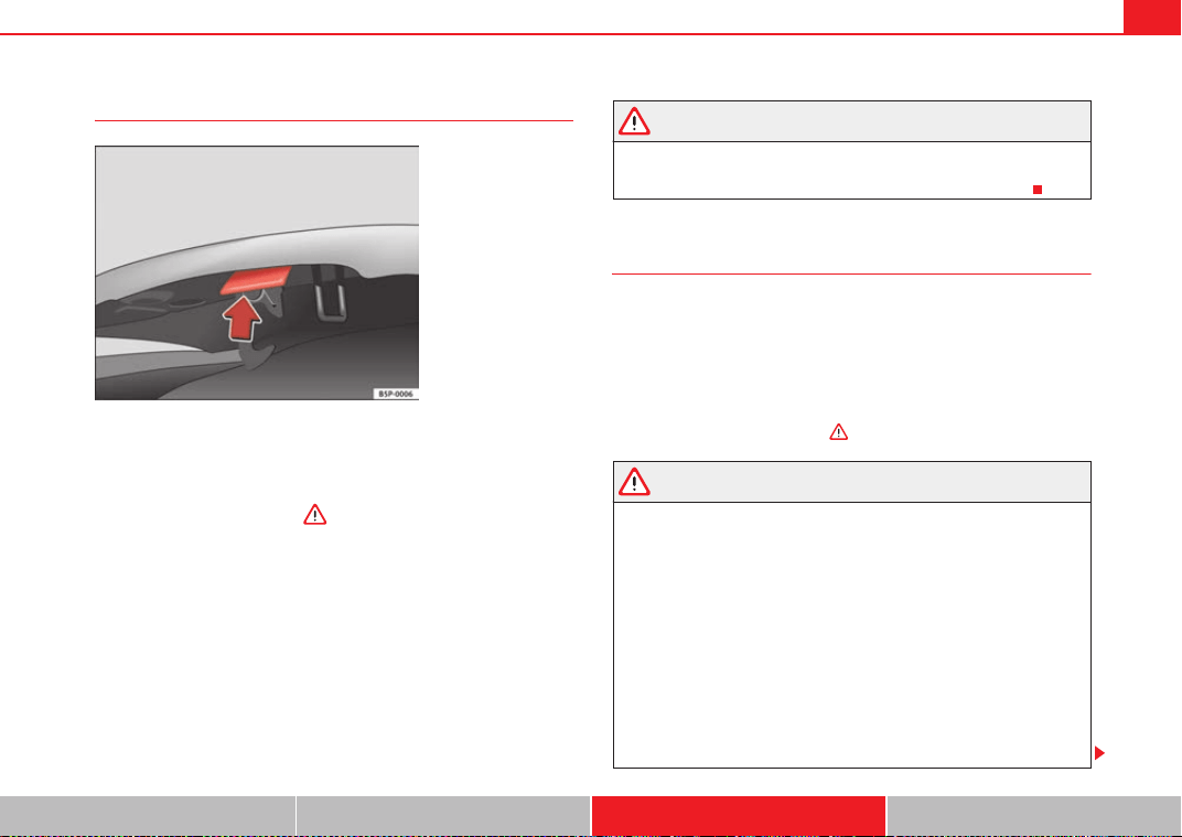
Checking and refilling levels 229
Safety First Operating Instructions Practical Tips Technical Specifications
Opening the bonnet
Before opening the bonnet make sure that the windscreen wiper
arms are not lifted away from the glass. Otherwise the paint may be
damaged.
– Lift the bonnet slightly ⇒ .
– Press the release catch under the bonnet upwards ⇒ fig. 176.
This will release the arrester hook under the bonnet.
– Open the bonnet.
The bonnet is held in position by a gas-filled strut.
WARNING
Never open the bonnet if you see steam or drips of coolant being released
from the engine compartment. Failure to comply could result in burns. Wait
until no steam or coolant can be seen before opening the bonnet.
Work in the engine compartment
Extra caution is necessary when working on components in
the engine compartment.
Always be aware of the danger of injury and scalding as well as the risk of
accident or even fire when working in the engine compartment (e.g. when
checking and refilling fluids). Always observe the warnings listed below and
follow all general safety precautions. The engine compartment of the vehicle
is a potentially hazardous area ⇒
WARNING
• Switch the engine off.
• Remove the ignition key.
• Apply the handbrake firmly.
• If your vehicle is equipped with a manual gearbox, place the gear lever
in neutral. If you are driving an automatic vehicle, place the selector lever
in position P.
• Wait for the engine to cool down.
• Children should not be allowed to approach the engine compartment.
• Never spill liquids used for vehicle operation on the engine compart-
ment, as these may catch fire (e.g. coolant).
• Take care not to cause short circuits in the electrical system, especially
when working on the battery.
Fig. 176 Release catch
under the bonnet
ExeoST_EN.book Seite 229 Freitag, 3. September 2010 11:41 11
Checking and refilling levels230
• Never touch the radiator fan while the engine is hot, as the fan could
start up suddenly.
• Never open the expansion tank when the engine is hot. The cooling
system is under pressure.
• Protect face, hands and arms from any hot steam or hot coolant fluid
released by covering the cap with a large, thick rag when opening the
expansion tank.
• If any tests have to be performed with the engine running, there is an
added safety risk from the rotating parts (e.g. drive belts, alternator, radi-
ator fan, etc.) and from the high-voltage ignition system.
• Observe the following additional warnings if work on the fuel system or
the electrical system is necessary:
− Always disconnect the battery.
− Do not smoke.
− Never work near open flames.
− Always keep an approved fire extinguisher immediately available.
Caution
When topping up fluids, make sure the correct fluid is put into the correct
filler opening. This can otherwise cause serious malfunctions or engine
damage.
For the sake of the environment
Inspect the ground underneath your vehicle regularly so that any leaks are
detected at an early stage. If you find spots of oil or other fluids, have your
vehicle inspected at the workshop.
Note
On right-hand drive vehicles some of the reservoirs mentioned below are
located on the other side of the engine compartment.
Closing the bonnet
– To close the bonnet, push it down until it overcomes the spring
pressure.
– Let the bonnet engage in the locking part. Do not force it ⇒ .
WARNING
• For safety reasons the bonnet must always be completely closed when
the vehicle is moving. After closing it always check that it is properly
secured. The bonnet must be flush with the adjacent body panels.
• Should you notice that the bonnet is not safely secured when the
vehicle is moving, stop the vehicle immediately and close the bonnet.
Failure to do so could result in an accident.
Engine oil
General notes
The engine comes with a special, high quality, multi grade oil that can be
used in all seasons of the year except for those regions affected by extreme
cold.
WARNING (continued)
ExeoST_EN.book Seite 230 Freitag, 3. September 2010 11:41 11

Checking and refilling levels 231
Safety First Operating Instructions Practical Tips Technical Specifications
As the use of good quality oil is necessary for the correct operation and long
service life of the engine, when it becomes necessary to replenish or change
the oil, always use an oil that complies to the VW standards.
The specifications (VW standards) set out in the following page should
appear on the container of the service oil; when the container displays the
specific standards for petrol and diesel engines together, it means that the
oil can be used for both types of engines.
We recommend that the oil change, indicated in the Maintenance
Programme, be performed by an Authorised Service Centre or a qualified
workshop.
The correct oil specifications for your engine are listed in ⇒ page 231, “Oil
properties”.
Service intervals
Service intervals can be flexible (LongLife service) or fixed (dependent on
time/distance travelled).
If the PR code that appears on the back of the Maintenance Programme
booklet is QG1, this means that your vehicle has the LongLife service
programmed. If it has the codes QG0 or QG2 the interval service is dependent
on time/distance travelled.
Flexible service intervals (LongLife*)
Special oils and processes have been developed which, depending on the
characteristics and individual driving profiles, allow to extend the oil change
service (LongLife service intervals).
Because this oil is essential for extending the service intervals, it must only
be used observing the following indications:
• Avoid mixing it with oil for fixed service intervals.
• Only in exceptional circumstances, if the engine oil level is too low
⇒ page 232 and LongLife oil is not available, it is permitted to top up (once)
with oil for fixed service intervals (up to a maximum of 0.5 litres).
Fixed service intervals*
If your vehicle does not have the “LongLife service interval” or it has been
disabled (by request), you may use oils for fixed service intervals, which also
appear in ⇒ page 231, “Oil properties”. In this case, your vehicle must be
serviced after a fixed interval of 1 year / 15,000 km (whatever comes first)
⇒ Booklet “Maintenance Programme”.
• In exceptional circumstances, if the engine oil level is too low
⇒ page 232 and you cannot obtain the oil specified for your vehicle, you can
put in a small quantity of oil conforming to the specification ACEA A2 or
ACEA A3 (petrol engines) or ACEA B3 or ACEA B4 (diesel engines) (up to 0.5l).
Vehicles with diesel particulate filter*
All Exeo vehicles with a diesel engine have a diesel particulate filter and must
only be filled with VW 507 00 engine oil, which has a low level of soot forma-
tion. Using other types of oil will cause a higher soot concentration and
reduce the life of the DPF. Therefore:
• Avoid mixing this oil with other engine oils.
• Only in exceptional circumstances, if the engine oil level is too low
⇒ page 232 and you cannot obtain the oil specified for your vehicle, can you
put in a small quantity of oil (once) conforming to the VW 506 00, VW 506 01,
VW 505 00, VW 505 01 or ACEA B3 / ACEA B4 specification. (up to 0.5 l).
Oil properties
Engine type Specification
Petrol VW 502 00/ VW 504 00
Diesel. Engines with particu-
late filter (DPF)
a)
a)
Only use recommended oils, otherwise you may damage the engine.
VW 507 00
ExeoST_EN.book Seite 231 Freitag, 3. September 2010 11:41 11
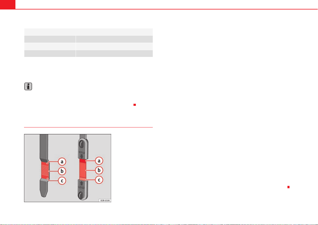
Checking and refilling levels232
Engine oil additives
No type of additive should be mixed with the engine oil. The deterioration
caused by these additives is not covered by the warranty.
Note
Before a long trip, we recommend finding an engine oil that conforms to the
corresponding VW specifications and keeping it in the vehicle. This way, the
correct engine oil will always be available for a top-up if needed.
Checking the oil level
Checking oil level
– Park the vehicle in a horizontal position.
– Briefly run the engine at idle speed until the service temperature
is reached and stop.
– Wait two minutes.
– Pull out the dipstick. Wipe the dipstick with a clean cloth and
insert it again, pushing it in as far as it will go.
– Then pull it out once more and check the oil level ⇒ page 232,
fig. 177. If the oil level is too low, add more engine oil
⇒ page 233.
Oil level in area
–Do not top up oil.
Oil level in area
–Oil can be topped up. After topping up the oil level should be in
area .
Oil level in area
–Oil must be topped up. After topping up the oil level should be in
area .
Depending on how you drive and the conditions in which the vehicle is used,
oil consumption can be up to 0.5 l/1000 km. Oil consumption is likely to be
higher for the first 5000 km. Therefore, the engine oil level must be checked
at regular intervals, preferably when filling the tank and before a journey.
Oils for LongLife service intervals*
Engine type Specification
Petrol VW 504 00
Diesel VW 507 00
Fig. 177 Markings on oil
dipstick
A
a
A
b
A
a
A
c
A
a
ExeoST_EN.book Seite 232 Freitag, 3. September 2010 11:41 11
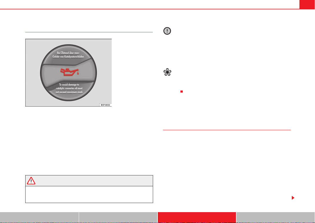
Checking and refilling levels 233
Safety First Operating Instructions Practical Tips Technical Specifications
Topping up the engine oil E
–Unscrew cap E from oil filler opening ⇒ page 301, fig. 248.
– Carefully put in the specified grade of oil ⇒ page 231, adding
0.5 litres at a time.
– After two minutes, check the oil level once again ⇒ page 232.
– Where necessary, add more engine oil.
– Replace the oil filler cap carefully and push the dipstick all the
way in.
WARNING
• When refilling with oil, make sure no oil falls onto hot engine parts.
Failure to comply could result in fire.
• Wash your skin thoroughly if it comes into contact with engine oil.
Caution
• The oil level must never be above area . This could damage the cata-
lytic converter or the engine. Contact a qualified workshop to drain the engine
oil if necessary.
• No additives should be used with engine oil. Any damage caused by the
use of such additives would not be covered by the factory warranty.
For the sake of the environment
• Oil must not be disposed of in the drain or on the ground.
• Always observe legal requirements when disposing of empty oil
canisters.
Cooling system
Coolant fluid
The purpose of the coolant fluid is to carry heat away from the
engine. The correct amount of antifreeze is decisive in
preventing the cooling system from freezing in winter.
The vehicle's engine cooling system is filled for life at the factory, so no
coolant needs to be changed. The coolant fluid consists of a mixture of water
and antifreeze G12++. This is a glycol-based antifreeze with anti-corrosion
additives.
Coolant fluid additive
The amount of antifreeze required depends on the temperatures to be
expected in the winter season. If the antifreeze concentration is too low the
coolant can freeze, resulting in failure of the cooling system and heater.
Fig. 178 In the engine
compartment: Engine oil
filler cap
A
a
ExeoST_EN.book Seite 233 Freitag, 3. September 2010 11:41 11
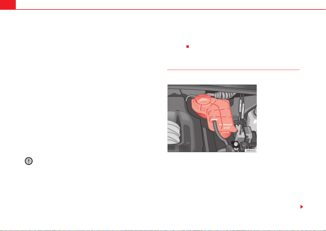
Checking and refilling levels234
The cooling system is filled at the factory with the correct amount of anti-
freeze for the country concerned.
In most cases, the mixture consists of 60% water and 40% antifreeze. This
mixture gives the required antifreeze protection at temperatures down to
-25 °C and particularly protects the metal parts of the cooling system against
corrosion. It also prevents scaling and significantly raises the boiling point of
the coolant fluid.
Countries with warm climate
The coolant fluid concentration must not be reduced by adding plain water,
even in the summer or in warm climates. The concentration of the antifreeze
must always be at least 40%.
Countries with cold climate
If greater freeze protection is required in very cold climates, the proportion of
G12++ antifreeze can be increased. A concentration of 60% offers antifreeze
protection of temperatures down to approx. -40 °C. However, the concentra-
tion of antifreeze must not exceed 60%, as the antifreeze protection would
then drop and the performance of the coolant system would suffer.
Vehicles for countries with cold climates (e.g. Sweden, Norway and Finland)
have factory-filled antifreeze protection for temperatures down to -35 °C. In
these countries, the concentration of antifreeze should always be at least
50%.
Caution
• It is advisable to have the cooling system checked before the winter
season to make sure that the antifreeze concentration is adequate for the
conditions to be expected. This applies particularly if you intend to take the
vehicle into a colder climate zone. If necessary, have the antifreeze concen-
tration increased to 50 - 60% as required.
• Use only G12++ antifreeze, an additive meeting the “TL-VW 774G” spec-
ification. Other antifreezes may give considerably inferior corrosion protec-
tion. The damage caused by the use of these antifreezes may lead to a loss of
coolant fluid, causing serious damage to the engine.
• G12++ antifreeze can be mixed only with antifreeze additives G11, G12
and G12+.
Checking the coolant level
The coolant level can be checked visually.
– Switch the ignition off.
– Check the coolant level on coolant fluid expansion tank
⇒ fig. 179. When the engine is cold, it should be between the
“min” and “max” marks. When the engine is hot, it may be
slightly above the “max” mark.
Its location is shown in the corresponding general overview of the engine
compartment.
Fig. 179 Engine compart-
ment: Coolant fluid
deposit
ExeoST_EN.book Seite 234 Freitag, 3. September 2010 11:41 11
Checking and refilling levels 235
Safety First Operating Instructions Practical Tips Technical Specifications
The coolant level should be checked with the engine switched off.
The coolant level is monitored by a warning lamp on the instrument panel
display ⇒ page 78. However, we recommend that it should be checked occa-
sionally.
Coolant fluid loss
Any loss of coolant fluid normally indicates a leak in the cooling system. In
this case the cooling system should be inspected by a qualified workshop
without delay. It is not sufficient merely to top up the coolant fluid.
If there are no leaks in the system, a loss of coolant fluid can only occur if the
coolant boils and is forced out of the system as a result of overheating.
Caution
Radiator sealants must not be added to the coolant fluid. Such additives
could seriously impair the function of the cooling system.
Topping up the coolant fluid
Be careful when topping up with coolant fluid.
– Switch the engine off.
– Wait for the engine to cool down.
– Cover the cap on the expansion tank ⇒ fig. 179 with a cloth, and
carefully unscrew the cap anti-clockwise ⇒ .
– Add coolant fluid.
– Screw on the cap tightly.
Make sure that the coolant fluid meets the required specifications
⇒ page 233, “Coolant fluid”. Do not use a different type of antifreeze if
G12++ antifreeze is not available. In this case, use only water and bring the
antifreeze concentration back up to the correct level as soon as possible.
Always top up with new coolant fluid.
Do not fill above the “max” mark. Excess coolant fluid is forced out of the
system through the valve in the filler cap when the engine gets hot.
If a lot of coolant fluid has been lost, wait for the engine to cool down before
putting in cold coolant. Failure to do so could result in serious engine
damage.
WARNING
• The cooling system is under pressure. Do not unscrew the cap on the
expansion tank when the engine is hot. Failure to comply could result in
burns.
• The antifreeze and coolant fluid can be a health hazard. Therefore, the
antifreeze should be stored in the original container in a safe place out of
reach of children. Failure to comply could result in poisoning.
For the sake of the environment
Drained off coolant should not be used again. Drain off the used coolant into
a suitable container and dispose of it in the proper manner (observe environ-
mental regulations).
ExeoST_EN.book Seite 235 Freitag, 3. September 2010 11:41 11
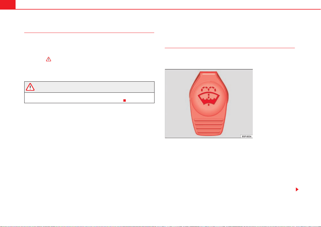
Checking and refilling levels236
Radiator fan
The radiator fan can start running spontaneously.
The auxiliary fan can continue to run for as long as 10 minutes after stopping
the engine, even after the ignition is switched off. It may also start running
suddenly ⇒ after some while if
• Stored heat raises the coolant temperature, or
• The hot engine compartment is additionally heated up by the sun.
WARNING
When working in the engine compartment be aware that the radiator fan
may start running suddenly, leading to the risk of injury.
Washer fluid and windscreen wiper blades
Windscreen washer system
Plain water is not sufficient for the windscreen washer
system.
The container for the windscreen washer contains the cleaning fluid for the
windscreen and the headlight washer system*. The container is located in the
engine compartment (front left). The filler cap is marked with the symbol
W
⇒ fig. 180.
The capacity of the container is listed in ⇒ page 301.
Plain water on its own is not enough to clean the glass properly. It is therefore
advisable to add a suitable washer fluid additive (with wax solvent) to the
water. A washer fluid with freeze-resistant additive should be used in winter.
Fig. 180 In the engine
compartment: Cap of
windscreen washer fluid
reservoir.
ExeoST_EN.book Seite 236 Freitag, 3. September 2010 11:41 11

Checking and refilling levels 237
Safety First Operating Instructions Practical Tips Technical Specifications
Caution
• Never put radiator antifreeze or other additives into the windscreen
washer fluid.
• Never use washer fluid which contains paint thinners or solvents as it can
damage the paintwork.
ExeoST_EN.book Seite 237 Freitag, 3. September 2010 11:41 11
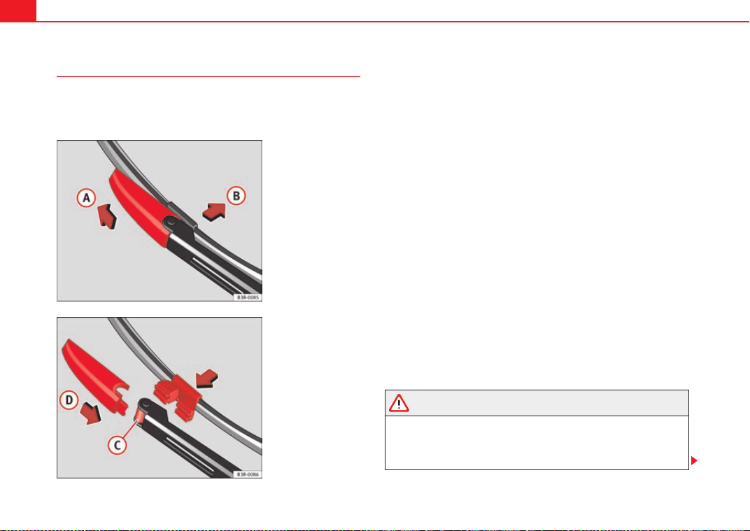
Checking and refilling levels238
Changing windscreen wiper blades
If the windscreen wiper blades are in perfect condition, you
will benefit from an improved visibility. Damaged wiper
blades should be replaced immediately.
Removing the wiper blade
– Lift the wiper arm away from the windscreen.
– Slide the retainer catch on the wiper blade in the direction indi-
cated ⇒ fig. 181 . Hold onto the wiper blade at the same time.
– Pull the wiper blade out of its mounting on the wiper arm.
Fitting the wiper blade
– Slide back the retainer catch on the new wiper blade. The
mounting on the wiper blade should now be visible.
– Fit the new wiper blade into the mounting on the wiper arm
⇒ fig. 182 .
– Slide the retainer catch on the wiper blade in direction so that
it clicks into place on the wiper arm.
– Fold the wiper arm back down onto the glass.
If the windscreen wipers smear, they should be replaced if they are
damaged, or cleaned if they are soiled.
If this does not produce the desired results, the setting angle of the wind-
screen wiper arms might be incorrect. They should be checked by a qualified
workshop and corrected if necessary.
WARNING
Do not drive unless you have good visibility through all windows!
• The ignition must not be switched on while the front wiper arms are in
a raised position. The wipers would return to their park position and
damage the paintwork on the bonnet.
Fig. 181 Removing the
wiper blade
Fig. 182 Fitting the wiper
blade
A
A
A
B
A
C
A
D
ExeoST_EN.book Seite 238 Freitag, 3. September 2010 11:41 11
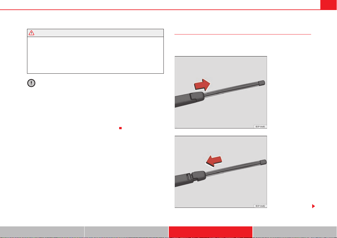
Checking and refilling levels 239
Safety First Operating Instructions Practical Tips Technical Specifications
• To prevent smearing on the windscreen, the wiper blades should be
cleaned regularly using a window cleaner solution. If the wiper blades are
very dirty (e.g. insects etc.), they should be cleaned using a sponge or
cloth. Failure to do so could result in an accident.
• For safety reasons, the wiper blades should be changed once or twice a
year.
Caution
• Damaged or dirty windscreen wipers could scratch the windscreen.
• Never use fuel, nail varnish remover, paint thinner or similar products to
clean the windows. This could damage the windscreen wiper blades.
• Never move the windscreen wiper or windscreen wiper arm manually. This
could cause damage.
• Do not pull the windscreen wipers forward unless they are in the service
position. Otherwise the bonnet could be damaged.
Changing the rear wiper blade
A good rear wiper blade is essential for clear rear vision.
Damaged wiper blades should be replaced immediately.
WARNING (continued)
Fig. 183 Removing rear
window wiper blade
Fig. 184 Fitting the rear
window wiper blade
ExeoST_EN.book Seite 239 Freitag, 3. September 2010 11:41 11
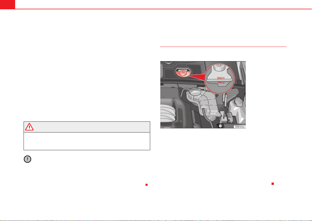
Checking and refilling levels240
Removing the wiper blade
– Lift the wiper arm away from the glass⇒ page 239, fig. 183
– Slide the blade adapter in the direction of the arrow and remove
the blade ⇒ page 239, fig. 183.
Fitting the wiper blade
– With one hand, hold the top end of the wiper arm.
– Place the blade as shown in the ⇒ page 239, fig. 184 and slide
the adapter along until it engages.
Check the condition of the wiper blade regularly. Change as required.
If the windscreen wiper scrapes, it should be replaced if damaged, or
cleaned if soiled.
If this is not sufficient, refer to a qualified workshop.
WARNING
Do not drive unless you have good visibility through all windows!
• Clean the windscreen wiper blades and all windows regularly.
• The wiper blades should be changed once or twice a year.
Caution
• A damaged or dirty window wiper could scratch the rear window.
• Never use fuel, nail varnish remover, paint thinner or similar products to
clean the window.
• Never move the windscreen wiper by hand. This could cause damage.
Brake fluid
Checking the brake fluid level
The brake fluid level can be checked visually.
The brake fluid level must be between the “Min” and “Max” ⇒ fig. 185 mark-
ings.
The fluid level may drop slightly after a period of time due to the automatic
compensation for brake pad wear. This is quite normal.
However, if the level goes down noticeably in a short time, or drops below the
“Min” mark, there may be a leak in the brake system. If the fluid level in the
reservoir is too low, this will be indicated by the brake warning lamp
⇒ page 70 and ⇒ page 77. If this should happen, take the vehicle to a qual-
ified workshop immediately and have the brake system inspected.
Fig. 185 Engine compart-
ment: markings on brake
fluid reservoir
ExeoST_EN.book Seite 240 Freitag, 3. September 2010 11:41 11
Checking and refilling levels 241
Safety First Operating Instructions Practical Tips Technical Specifications
Topping up and changing the brake fluid
It is best to have the brake fluid changed by a professional.
Brake fluid absorbs moisture. Therefore, in the course of time it will absorb
water from the air. If the water content in the brake fluid is too high, the brake
system could corrode. In addition, the boiling point of the brake fluid will be
considerably reduced. This could adversely affect the braking ability in
certain circumstances.
For this reason the brake fluid must be changed periodically.
Your vehicle's Service Plan will tell you when the brake fluid has to be
renewed.
We recommend you have the brake fluid changed as part of a regular Inspec-
tion Service at a workshop. They are familiar with the procedure and have the
necessary special tools and spare parts as well as the proper facilities for
disposing of the old fluid.
Use only approved brake fluid. Specialised workshops are informed about
the factory-approved brake fluid -DOT 4-. The brake fluid must be new.
WARNING
• Brake fluid must always be kept closed in its original container. Keep
out of the reach of children. Failure to comply could result in poisoning.
• If the brake fluid is left in the system for too long and the brakes are
subjected to heavy use, vapour bubbles may form in the brake system. This
would seriously affect the efficiency of the brakes and the safety of the
vehicle, leading to the risk of accident.
Caution
Please note that brake fluid will attack the paintwork on contact.
For the sake of the environment
The brake pads and fluid must be collected and disposed of according the
applicable regulations. The SEAT service network has the necessary equip-
ment and qualified personnel for collecting and disposing of this waste
material.
Vehicle battery
General notes
All work on batteries requires specialist knowledge.
The battery is virtually maintenance-free and is checked in the Inspection
Services.
We recommend replacing the battery after 5 years.
Disconnecting the battery
If the battery is disconnected, some of the vehicle's functions will become
inoperative (e.g. electric windows). These functions will require resetting
after the battery is reconnected. For this reason, the battery should only be
disconnected from the vehicle's electrical system when absolutely necessary.
Long periods of non-use
The battery will gradually lose its charge because certain electrical equip-
ment continues to draw current even when the ignition is off. If you park the
vehicle for long periods of time in winter you should take the battery out of
the vehicle and store it in a place protected from frost. This way it will not
freeze and become damaged. At warm outside temperatures it is sufficient to
disconnect the negative terminal of the battery. Even when the battery is not
connected you should charge it from time to time.
ExeoST_EN.book Seite 241 Freitag, 3. September 2010 11:41 11

Checking and refilling levels242
Winter operation
The battery is drained more in cold weather, which means that the starting
power is reduced. For this reason, have the battery checked and charged if
necessary before the start of winter.
Replacing the battery
A replacement battery must have the same capacity, voltage and current
rating. It must also have the same dimensions as the original, factory-fitted
battery and have sealed caps. The SEAT batteries which have been specially
developed fulfil the maintenance, performance and safety specifications for
your vehicle.
We recommend you use maintenance-free batteries.
WARNING
• All work on batteries requires specialist knowledge. If work is required
on the battery, this should be performed by a Technical Service or qualified
workshop. Danger of caustic burns and explosion!
• The battery must not be opened. Never try to change the battery's
liquid level. Explosive gas is released from the battery that could cause an
explosion.
Caution
• The battery holder and clamps must always be correctly secured.
• Before starting any work on the battery, always observe the warnings
listed under ⇒ .
For the sake of the environment
¡ Batteries contain toxic substances including sulphuric acid and lead.
Therefore, they must be disposed of in line with environmental regulations
and must not be disposed of with ordinary household waste. Make sure
disconnected batteries cannot tip over. Sulphuric acid could be spilt!
Important safety warnings for handling a vehicle battery
The battery is located at the back of the engine compartment ⇒ page 301.
WARNING
Always be aware of the danger of injury and chemical burns as well as the
risk of accident or fire when working on the battery and the electrical
system:
•
Wear eye protection. Protect your eyes, skin and clothing from acid and
particles containing lead.
• Battery acid is very corrosive and caustic. Wear protective gloves and
eye protection. Do not tilt the batteries. This could spill acid through the
vents. Rinse battery acid from eyes immediately for several minutes with
clear water. Then seek medical care immediately. Neutralise any acid
splashes on the skin or clothing with a soapy solution, and rinse off with
plenty of water. If acid is swallowed by mistake, consult a doctor immedi-
ately.
• Fires, sparks, open flames and smoking are prohibited. When handling
cables and electrical equipment, avoid causing sparks and electrostatic
charge. Never short the battery terminals. High-energy sparks can cause
injury.
Wear eye protection
Battery acid is very corrosive and caustic. Wear protective
gloves and eye protection!
Fires, sparks, open flames and smoking are prohibited!
A highly explosive mixture of gases is released when the battery
is under charge.
Keep children away from acid and batteries!
ExeoST_EN.book Seite 242 Freitag, 3. September 2010 11:41 11
Checking and refilling levels 243
Safety First Operating Instructions Practical Tips Technical Specifications
• A highly explosive mixture of gases is released when the battery is
under charge. The batteries should be charged in a well-ventilated room
only.
• Keep children away from acid and batteries.
• Before working on the electrical system, you must switch off the
engine, the ignition and all consumers. The negative cable on the battery
must be disconnected. When a light bulb is changed, you need only switch
off the light.
• Deactivate the anti-theft alarm by unlocking the vehicle before you
disconnect the battery! The alarm will otherwise be triggered.
• When disconnecting the battery from the vehicle electrical system,
disconnect first the negative cable and then the positive cable.
• Switch off all electrical consumers before reconnecting the battery.
Reconnect first the positive cable and then the negative cable. Never
reverse the polarity of the connections. This could cause an electrical fire.
• Never charge a frozen battery, or one which has thawed. This could
result in explosions and chemical burns. Always replace a battery which
has frozen. A flat battery can freeze at temperatures around 0 °C.
• Ensure that the vent hose is always connected to the battery.
• Never use a defective battery. This could cause an explosion. Replace a
damaged battery immediately.
Caution
• Never disconnect the battery if the ignition is switched on or if the engine
is running. This could damage the electrical system or electronic compo-
nents.
• Do not expose the battery to direct sunlight over a long period of time, as
the intense ultraviolet radiation can damage the battery housing.
• If the vehicle is left standing in cold conditions for a long period, protect
the battery from frost. If it freezes it will be damaged.
Charging the battery
A fully-charged battery is important for reliable starting.
–Note the warnings ⇒ in “Important safety warnings for
handling a vehicle battery” on page 242 and ⇒ .
– Switch off the ignition and all electrical equipment.
– Only if fast-charging: both battery cables must be disconnected
(first the negative cable, then the positive cable).
– Connect the charger cables to the battery terminals, noting the
colour code (red = positive; black or brown = negative).
– Now connect the battery charger to the power socket and switch
on.
– After charging the battery: switch off the battery charger and
disconnect the power point cable.
– Finally disconnect the charger cables from the battery.
– If necessary, reconnect both battery cables to the battery (first
the positive cable, then the negative cable).
When charging with a low current (for instance with a small battery charger)
the battery does not normally have to be disconnected. However, both
battery cables must be disconnected before fast-charging the battery with a
high current. However, always follow the instructions given by the manufac-
turer of the battery charger.
The fast-charging procedure for a battery is dangerous ⇒ in “Important
safety warnings for handling a vehicle battery” on page 242, as it requires a
special charger and the corresponding level of knowledge. We therefore
recommend that this work should only be performed by a qualified workshop.
WARNING (continued)
ExeoST_EN.book Seite 243 Freitag, 3. September 2010 11:41 11
Checking and refilling levels244
A flat battery can freeze at temperatures of around 0 °C. The battery must be
defrosted before charging ⇒ . It is advisable to replace the battery if it has
frozen, because the ice can crack the battery casing and allow the battery
acid to escape.
The battery caps should not be opened while the battery is being charged.
WARNING
Never charge a frozen battery. Failure to comply could result in an
explosion.
ExeoST_EN.book Seite 244 Freitag, 3. September 2010 11:41 11
Wheels and tyres 245
Safety First Operating Instructions Practical Tips Technical Specifications
Wheels and tyres
Wheels
General notes
Avoiding damage
– If you have to drive over a kerb or similar obstacle, drive very
slowly and at a right angle.
– Keep grease, oil and fuel off the tyres.
– Inspect the tyres regularly for damage (cuts, cracks or blisters,
etc.). Remove any foreign objects embedded in the treads.
Storing tyres
– Mark tyres when you remove them to indicate the direction of
rotation. This ensures you will be able to install them correctly
when you replace them.
– When removed, the wheels and/or tyres should be stored in a
cool, dry and preferably dark location.
– Store tyres in a vertical position if they are not fitted on wheel
rims.
New tyres
New tyres have to be run in.
The tread depth of new tyres may vary, according to the type and make of tyre
and the tread pattern.
Concealed damage
Damage to tyres and rims is often not readily visible. If you notice unusual
vibrations or the vehicle pulling to one side, this may indicate that one of the
tyres is damaged. The tyres should be checked immediately by an Authorised
Service Centre.
Tyres with directional tread pattern
An arrow on the tyre sidewall indicates the direction of rotation on tyres with
directional tread. Always observe the direction of rotation indicated when
fitting the wheel. This guarantees optimum grip and helps to avoid aqua-
planing, excessive noise and wear.
WARNING
• New tyres do not have maximum grip during the first 500 km. Drive
particularly carefully to avoid possible accidents.
• Never drive with damaged tyres. This may cause an accident.
• If you notice unusual vibrations or if the vehicle pulls to one side when
driving, stop the vehicle immediately and check the tyres for damage.
Checking tyre pressure
The correct tyre pressure can be seen on the sticker on the
inside of the tank flap.
1. Read the required tyre inflation pressure from the sticker. The
values refer to Summer tyres. For Winter tyres, you must add 0.2
bar to the values given on the sticker.
ExeoST_EN.book Seite 245 Freitag, 3. September 2010 11:41 11
Wheels and tyres246
2. The tyre pressures should only be checked when the tyres are
cold. The slightly raised pressures of warm tyres must not be
reduced.
3. Adjust the tyre pressure to the load you are carrying.
Tyre pressure
The correct tyre pressure is especially important at high speeds. The pressure
should therefore be checked at least once a month and before starting a
journey.
The sticker with the tyre pressure values can be found on the inside of the
tank flap. The tyre pressure values given are for cold tyres. Do not reduce the
slightly raised pressures of warm tyres ⇒ .
WARNING
• Check the tyre pressure at least once per month. Checking the tyre
pressure is very important. If the tyre pressure is too high or too low, there
is an increased danger of accidents - particularly at high speeds.
• A tyre can easily burst if the pressure is too low, causing an accident!
• At continuously high speeds, a tyre with insufficient pressure flexes
more. In this way it becomes too hot, and this can cause tread separation
and tyre blow-out. Always observe the recommended tyre pressures.
• If the tyre pressure is too low or too high, the tyres will wear prema-
turely and the vehicle will not handle well. Risk of accident!
For the sake of the environment
Under-inflated tyres will increase fuel consumption.
Tyre pressure monitoring*
The tyre pressure monitoring system constantly checks the
pressure of the tyres.
The system warns the driver in the event of a loss of pressure by means of
symbols and messages in the instrument panel display.
Note that tyre pressure also depends on tyre temperature. Tyre pressure
increases about 0.1 bar for each 10 °C in tyre temperature increase. The tyre
heats up while the vehicle is being driven and the tyre pressure will rise
accordingly. For this reason, you should only adjust the tyre pressures when
they are cold (i.e. approximately at ambient temperature).
To ensure that the tyre pressure monitoring system works reliably, you should
check and, if necessary, adjust the tyre pressures at regular intervals and
store the correct pressures (reference values) in the system.
A tyre pressure information label is attached to the inside of the fuel tank flap.
WARNING
• Never adjust tyre pressure when the tyres are hot. This may damage or
even burst the tyres. Risk of accident!
• An insufficiently inflated tyre flexes a lot more at high speeds and
causes significant heating of the tyre. Under these conditions, the tyre
bead may be released or the tyre may burst. Risk of accident!
For the sake of the environment
Under-inflated tyres lead to increased fuel consumption and tyre wear.
ExeoST_EN.book Seite 246 Freitag, 3. September 2010 11:41 11
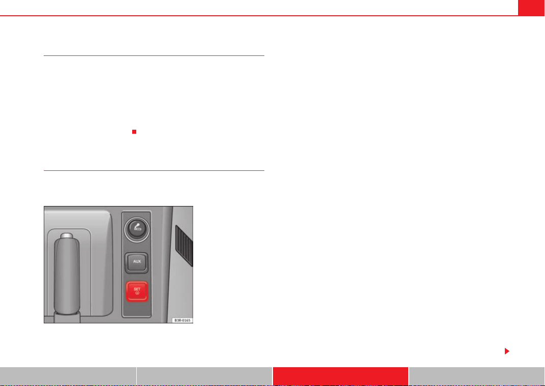
Wheels and tyres 247
Safety First Operating Instructions Practical Tips Technical Specifications
Significant tyre pressure loss
The tyre symbol ~ is displayed and indicates that the tyre pressure of at least
one tyre is insufficient.
- Stop the vehicle.
- Switch the engine off.
- Check the tyre(s).
- Change the tyre if necessary.
Tyre pressure monitoring (RKA+)*
The tyre pressure monitor display on the instrument panel
indicates if the pressure is too low.
The tyre pressure monitoring system makes use of the ABS sensors to
compare the rolling circumference and the frequency characteristics of the
wheels. If the rolling circumference or frequency characteristic changes on
one or more wheels, the tyre pressure warning lamp
~ will light up. The fault
will also be indicated by a warning buzzer. The position of the affected tyre
will also be shown (if only one tyre is affected) on the centre display of the
instrument panel.
The rolling circumference and frequency characteristics can change if:
• the tyre pressure is too low.
• the tyre has suffered structural damage.
• the wheels or the inflation pressures have been changed without initial-
ising the system (see Adjusting the tyre pressure settings).
• there is a greater load on the wheels of one axle (e.g. if you are carrying
more passengers or luggage).
• the road surface under the left wheels is different to the road surface
under the right wheels for a long period.
• when driving with snow chains.
Adjusting the tyre pressure settings (initialising the tyre pressure
monitoring system)
After any incident regarding the wheels of your vehicle, e.g. after modify the
tyre pressure ⇒ page 248 or after changing or swapping around wheels ⇒
page 180 - with the vehicle at a standstill and the engine running - press
⇒ fig. 186. The yellow warning lamp
~ will light up. Hold the button down
for 2 seconds until the warning lamp goes out and an acoustic warning is
given. You can now release the button.
If the wheels are subjected to extreme stress (e.g. heavy load), the tyre pres-
sure must be increased to the recommended value for the maximum load
(see the adhesive label on the inside of the fuel tank flap) and then initialise
the system.
Tyre pressure warning lamp on
When you switch on the ignition, the tyre pressure warning lamp
~ will light
up for about 2 seconds. There is a fault in the system if the indicator stays on
permanently after switching on the ignition. The instrument panel also
Fig. 186 Detailed view of
the centre console: Button
for the tyre pressure
monitoring system
ExeoST_EN.book Seite 247 Freitag, 3. September 2010 11:41 11
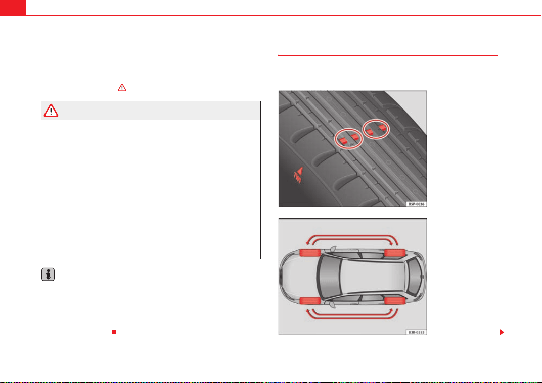
Wheels and tyres248
display TMPS (Tyre Pressure Monitoring System). Please contact the nearest
qualified workshop as soon as possible.
The tyre pressure warning lamp
~ lights up if the tyre pressure on one or
more wheels is significantly lower than the tyre pressure setting which was
confirmed by the driver ⇒ .
WARNING
• If the tyre pressure warning lamp lights up ~ you must slow down
immediately and avoid any severe braking or steering manoeuvres. Stop
the vehicle as soon as possible and check the tyres and their pressure.
• The driver is responsible for maintaining correct tyre pressures. There-
fore, the tyre pressure must be regularly checked.
• Under certain conditions (e.g. driving at high speeds, on ice and snow
or on poor road surfaces) the tyre pressure warning lamp
~ may not light
up immediately or not at all.
• Please ask your Dealer or qualified workshop whether run-flat tyres can
be used on your vehicle. Fitting this type of tyre in an undue manner could
lead to your driving licence being taken away from you. Furthermore, it may
led to damage to the vehicle or, under certain circumstances, may cause
accidents.
• If you change normal tyres for run-flat tyres or vice versa, the control
unit must be reprogrammed by the Dealer or a qualified workshop.
Note
If you did not press the button for the tyre pressure monitoring system to
confirm a new tyre pressure setting after making changes to the tyre pres-
sures or changing one or more wheels, the warning lamp
~ may light up
although the tyre pressures are correct. In this case, stop the vehicle as soon
as possible and, after examining the tyres, press the button for the tyre pres-
sure monitoring system.
Tyre service life
The service life of tyres is dependent on tyre pressure, driving
style and fitting.
Fig. 187 Tyre tread wear
indicators
Fig. 188 Diagram for
changing wheels
ExeoST_EN.book Seite 248 Freitag, 3. September 2010 11:41 11
Wheels and tyres 249
Safety First Operating Instructions Practical Tips Technical Specifications
Wear indicators
The original tyres on your vehicle have 1.6 mm high tread wear indicators
⇒ page 248, fig. 187, running across the tread. Depending on the make,
there will be six to eight of them evenly spaced around the tyre. Markings on
the tyre sidewall (for instance the letters “TWI” or other symbols) indicate the
positions of the tread wear indicators. The minimum tread depth required by
law is 1.6 mm (measured in the tread grooves next to the tread wear indica-
tors). Worn tyres must be replaced. Different figures may apply in export
countries ⇒ .
Tyre pressure
Under-inflation or over-inflation will reduce the life of the tyres considerably
and also impair the vehicle's handling. The inflation pressures are listed on a
sticker on the inside of the fuel tank flap.
Correct inflation pressures are very important, especially at high speeds. The
pressure should therefore be checked at least once a month and before
starting any long journey.
Tyre pressure monitoring (RKA+)*
Monitoring of the tyre pressures is based on the tyre pressures you have
stored. The tyre pressure monitoring system cannot function as intended if
you store tyre pressure settings for a normal load, but then drive with the
vehicle fully laden. The tyre pressure must be adapted to the actual load and
stored accordingly in the tyre pressure monitoring system ⇒ page 247.
Driving style
Fast cornering, heavy acceleration and hard braking all increase tyre wear.
Changing wheels around
If the front tyres are worn considerably more than the rear ones it is advisable
to change them around as shown ⇒ page 248, fig. 188. All the tyres will then
last for about the same time.
Wheel balance
The wheels on new vehicles are balanced. However, various factors encoun-
tered in normal driving can cause them to become unbalanced, which results
in steering vibration.
Unbalanced wheels should be rebalanced, as they otherwise cause excessive
wear on steering, suspension and tyres. A wheel must also be rebalanced
when a new tyre is fitted.
Incorrect wheel alignment
Incorrect wheel alignment causes excessive tyre wear, impairing the safety of
the vehicle. If tyres show excessive wear, you should have the wheel align-
ment checked by an Authorised Service Centre.
WARNING
There is a serious danger of accidents if a tyre bursts during driving!
• The tyres must be replaced at the latest when the tread is worn down to
the tread wear indicators. Failure to do so could result in an accident. Worn
tyres do not grip well at high speeds on wet roads. There is also a greater
risk of aquaplaning.
• At continuously high speeds, a tyre with insufficient pressure flexes
more. This causes it to overheat. This can cause tread separation and tyre
blow-out. Risk of accident. Always observe the recommended tyre pres-
sures.
• If tyres show excessive wear, you should have the running gear checked
by an Authorised Service Centre.
• Keep chemicals such as oil, fuel and brake fluid away from tyres.
• Damaged wheels and tyres must be replaced immediately!
For the sake of the environment
Under-inflated tyres will increase fuel consumption.
ExeoST_EN.book Seite 249 Freitag, 3. September 2010 11:41 11
Wheels and tyres250
Run-flat tyres*
Run-flat tyres allow you to continue driving even with a punc-
tured tyre, in the majority of cases.
In vehicles that are factory-fitted with run-flat tyres
3)
the loss of tyre
pressure is indicated on the instrument panel.
Driving with run-flat tyres (emergency running)
– Leave the ESP/TCS (Electronic Stability Programme) switched on,
or switch on ⇒ page 68.
– Continue driving carefully and slowly (80 km/h maximum).
– Avoid sudden manoeuvres and sharp turns.
– Avoid driving over obstacles (for example kerbs) or potholes.
– Look out for the ESP/TCS intervening often, smoke coming from
the tyres or the smell of rubber, the vehicle vibrating or a clat-
tering noise. If any of these occur, stop the vehicle.
The run-flat tyres have a tag on the side of the tyre, with the description:
“DSST”, “Eufonia”, “RFT”, “ROF”, “RSC”, “SSR” or “ZP”.
The sides of this type of tyre are reinforced. When the tyres lose air they are
supported on the sides (emergency driving).
The loss of pressure in the tyre is shown on the instrument panel. You can
then drive a maximum of 80 km and if the circumstances are favourable (for
example, low load), even more.
The damaged tyre should be changed as soon as possible. The rim should be
checked in a specialist workshop to detect possible damage and replace it if
necessary. We recommend you contact Technical Service. If more than one
tyre is being used under emergency conditions, this reduces the distance
which can be travelled.
Starting driving in emergency conditions
When loss in tyre pressure is displayed on the instrument panel, this means
that at least one tyre is being driven in emergency conditions ⇒ .
End of emergency operation
Do not drive on if:
• smoke is coming from one of the tyres,
• there is a smell of rubber,
• the vehicle vibrates,
• there is a rattling noise.
When is it no longer possible to continue driving even using run-flat tyres?
• If the Electronic Stability Programme (ESP) is out of operation.
• If the tyre pressure monitoring system* does not work.
• If one of the tyres has been severely damaged in an accident, etc. If a tyre
has been badly damaged there is a risk that parts of the tread can be thrown
off and cause damage to the fuel lines, brake pipes or fuel filler.
• It is also advisable to stop driving if severe vibrations occur, or if the wheel
starts overheating and gives off smoke.
WARNING
When driving in emergency conditions, the driving quality of the vehicle is
considerably impaired.
• The maximum permitted speed of 80 km/h is subject to road and
weather conditions. Please observe legal requirements when doing so.
• Avoid sharp turns and rapid manoeuvres, and brake earlier than usual.
• Avoid driving over obstacles (for example kerbs) or potholes.
3)
Depending upon version and country.
ExeoST_EN.book Seite 250 Freitag, 3. September 2010 11:41 11
Wheels and tyres 251
Safety First Operating Instructions Practical Tips Technical Specifications
• If one or more tyres are being driven in emergency conditions, the
driving quality of the vehicle is impaired and there is a risk of accident.
Note
• The run-flat tyres do not “deflate” on losing pressure because they are
supported on the reinforced sides. Therefore defects in the tyre cannot be
detected with a visual inspection.
• Snow chains must not be used on front tyres used in emergency
conditions.
New tyres and wheels
New tyres and wheels have to be run in.
The tyres and wheel rims are an essential part of the vehicle's design. The
tyres and rims approved by SEAT are specially matched to the characteristics
of the vehicle and make a major contribution to good road holding and safe
handling ⇒ .
Tyres should be replaced at least in pairs and not individually (i.e. both front
tyres or both rear tyres together). A knowledge of tyre designations makes it
easier to choose the correct tyres. Radial tyres have the tyre designations
marked on the sidewall, for example:
195/65 R15 91T
This contains the following information:
195 Tyre width in mm
65 Height/width ratio in %
RTyre construction: Radial
15 Rim diameter in inches
91 Load rating code
TSpeed rating
The tyres could also have the following information:
• A direction of rotation symbol
• “Reinforced” denotes heavy-duty tyres.
The manufacturing date is also indicated on the tyre sidewall (possibly only
on the inner side of the wheel).
“DOT ... 1103...” means, for example, that the tyre was produced in the 11th
week of 2003.
We recommend that work on tyres and wheels be carried out by an Authorised
Service Centre. They are familiar with the procedure and have the necessary
special tools and spare parts as well as the proper facilities for disposing of
the old tyres.
Any Authorised Service Centre has full information on the technical require-
ments when installing or changing tyres, wheels or wheel trims.
WARNING
• We recommend that you use only wheels and tyres which have been
approved by SEAT for your model. Failure to do so could impair vehicle
handling. Risk of accident.
• Avoid running the vehicle on tyres that are more than six years old. If
you have no alternative, you should drive slowly and with extra care at all
times.
• Never use old tyres or those with an unknown history of use.
• If wheel trims are retrofitted, you must ensure that the flow of air to the
brakes is not restricted. This could cause them to overheat.
• All four wheels must be fitted with radial tyres of the same type, size
(rolling circumference) and the same tread pattern.
WARNING (continued)
ExeoST_EN.book Seite 251 Freitag, 3. September 2010 11:41 11
Wheels and tyres252
For the sake of the environment
Old tyres must be disposed of according to the laws in the country concerned.
Note
• For technical reasons, it is not generally possible to use the wheels from
other vehicles. This can also apply to wheels of the same model. The use of
wheels or tyres which have not been approved by SEAT for use with your
model may invalidate the vehicle's type approval for use on public roads.
• If the spare tyre is not the same as the tyres that are mounted on the
vehicle - for example with winter tyres - you should only use the spare tyre for
a short period of time and drive with extra care. Refit the normal road wheel
as soon as possible.
Wheel bolts
Wheel bolts must be tightened to the correct torque.
The design of wheel bolts is matched to the rims. If different wheel rims are
fitted, the correct wheel bolts with the right length and correctly shaped bolt
heads must be used. This ensures that wheels are fitted securely and that the
brake system functions correctly.
In certain circumstances, you should not use wheel bolts from a different
vehicle, even if it is the same model ⇒ page 223.
After the wheels have been changed, the tightening torque of the wheel bolts
should be checked as soon as possible with a torque wrench. ⇒ The tight-
ening torque for steel and alloy wheels is 120 Nm.
WARNING
If the wheel bolts are not tightened correctly, the wheel could become
loose while driving. Risk of accident.
• The wheel bolts must be clean and turn easily. Never apply grease or oil
to them.
• Use only wheel bolts which belong to the wheel.
• If the torque of the wheel bolts is too low, they could loosen whilst the
vehicle is in motion. Risk of accident! If the tightening torque is too high,
the wheel bolts and threads can be damaged.
Caution
The prescribed tightening torque for wheel bolts for steel and alloy wheels is
120 Nm.
Winter tyres
Winter tyres will improve the vehicles handling on snow and
ice.
In winter conditions winter tyres will considerably improve the vehicle's
handling. The design of summer tyres (width, rubber compound, tread
pattern) gives less grip on ice and snow.
Winter tyres must be inflated to a pressure 0.2 bar higher than the pressures
specified for summer tyres (see sticker on tank flap).
Winter tyres must be fitted on all four wheels.
Information on permitted winter tyre sizes can be found in the vehicle's regis-
tration documents. Use only radial winter tyres. All tyre sizes listed in the
vehicle documentation also apply to winter tyres.
ExeoST_EN.book Seite 252 Freitag, 3. September 2010 11:41 11
Wheels and tyres 253
Safety First Operating Instructions Practical Tips Technical Specifications
Winter tyres lose their effectiveness when the tread is worn down to a depth
of 4 mm.
The speed rating code ⇒ page 251, “New tyres and wheels” determines the
following speed limits for winter tyres: ⇒
Q max. 160 km/h
S max. 180 km/h
T max. 190 km/h
H max. 210 km/h
In some countries, vehicles which can exceed the speed rating of the fitted
tyre must have an appropriate sticker in the driver's field of view. These
stickers are available from your Authorised Service Centre. The legal require-
ments of each country must be followed.
Do not have winter tyres fitted for unnecessarily long periods. Vehicles with
summer tyres handle better when the roads are free of snow and ice.
If you have a flat tyre, please refer to the notes on the spare wheel
⇒ page 251, “New tyres and wheels”.
WARNING
The maximum speed for the winter tyres must not be exceeded. Otherwise,
this could lead to tyre damage and risk of accident.
For the sake of the environment
Fit your summer tyres again as soon as possible. They are quieter, do not wear
so quickly and reduce fuel consumption.
Snow chains
Snow chains may be fitted only to the front wheels, and only to certain tyre
sizes ⇒ page 300.
Remove wheel hub covers and trim rings before fitting snow chains. For safety
reasons cover caps, available in any Authorised Service Centre, must then be
fitted over the wheel bolts.
WARNING
Observe the fitting instructions provided by the snow chain manufacturer.
Caution
You must remove the snow chains to drive on roads which are free of snow.
Otherwise they will impair handling, damage the tyres and wear out very
quickly.
Note
• In some countries, the speed limit for using snow chains is 50 km/h. The
legal requirements of the country should be followed.
• We recommend that you ask your Authorised Service Centre for informa-
tion about appropriate wheel, tyre and snow chain size.
205/55 R16 15 mm chains
225/45 R17 9 mm chains
225/40 R18 7 mm chains
ExeoST_EN.book Seite 253 Freitag, 3. September 2010 11:41 11
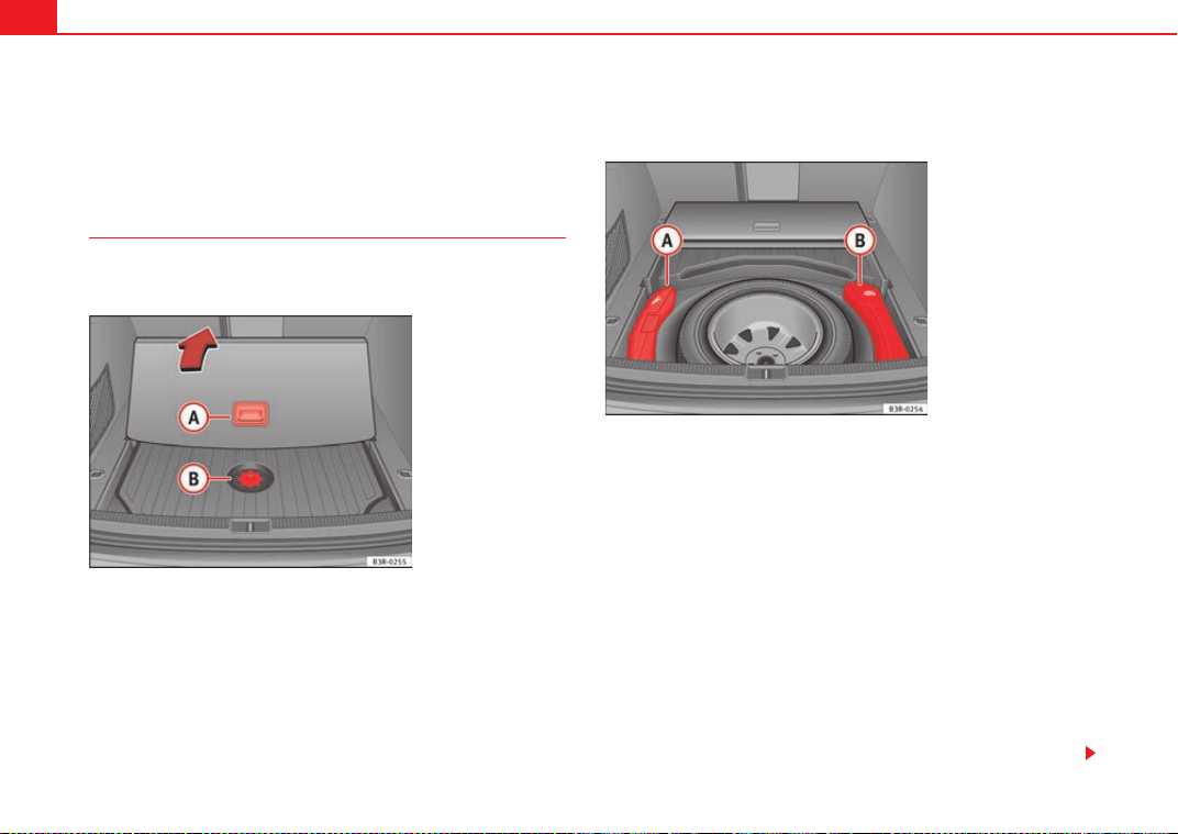
If and when254
If and when
Tools, tyre repair kit and spare wheel
Tools
The tools and jack are stored under the floor panel in the
luggage compartment.
The tools and jack ⇒ fig. 190 for vehicles with a spare wheel
and for vehicles with the tyre repair kit are stored under the floor
panel in the luggage compartment.
– Take hold of handle and fold back the floor panel in the
luggage compartment ⇒ fig. 189.
– Unscrew the attachment screw from cover ⇒ fig. 189.
– Remove cover.
– Release the toolbox by pulling up the handle on the box (vehicles
equipped with spare wheel).
– Take out the tools or jack.
The tool kit includes:
Fig. 189 Access to the
toolbox and jack
Fig. 190 Toolbox and jac
k
A
A
A
B
A
A
A
B
ExeoST_EN.book Seite 254 Freitag, 3. September 2010 11:41 11
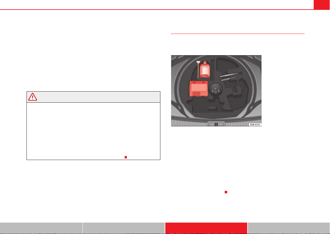
If and when 255
Safety First Operating Instructions Practical Tips Technical Specifications
• A hook for removing wheel covers* or hub caps
• Box spanner for wheel bolts
• A screwdriver with reversible blade
• Towing eye
• An adapter for the anti-theft wheel bolts*
Before replacing the jack in the storage bin, wind down the arm of the jack as
far as it will go.
Some of the tools listed are only provided in certain models or are optional
extras.
WARNING
• Do not use the hexagonal socket in the screwdriver handle to tighten
the wheel bolts, as with this it is not possible to tighten the bolts to the
required torque. Risk of accident.
• The factory-supplied jack is only designed for changing wheels on this
model. On no account attempt to use it for lifting heavier vehicles or other
loads. Risk of injury.
• Never start the engine when the vehicle is raised. Failure to do so could
result in an accident.
• If work is to be carried out underneath the vehicle, this must be secured
by suitable stands. Otherwise, there is a risk of injury.
Tyre mobility system
The tyre mobility system is stored under the floor panel in the
luggage compartment.
– Take hold of the handle and fold back the floor panel in the
luggage compartment.
– Take out the tyre mobility system.
Your vehicle is equipped with a Tyre Mobility System in case of a puncture.
The tyre mobility system consists of a container with sealing compound and
a compressor to generate the required tyre pressure.
Instructions for using the sealant compound and the compressor are
included with the sealant can.
Fig. 191 Tyre Mobility
System under floor panel
in luggage compartment
ExeoST_EN.book Seite 255 Freitag, 3. September 2010 11:41 11
If and when256
Spare steel rim wheel
The spare steel rim wheel is carried in the wheel well under
the floor panel in the luggage compartment. It is only
intended for temporary use over short distances.
Taking out the spare wheel
–Turn the plastic knob ⇒ fig. 192 anti-clockwise.
– Take out the spare wheel.
Securing the defective wheel in the spare wheel well
– Place wheel in spare wheel well in the luggage compartment.
– Secure the wheel by turning plastic knob clockwise.
– Replace the floor panel before closing the tailgate.
Your vehicle can be factory-equipped with a spare steel wheel. The spare
wheel does not usually meet the same performance standards as the wheels
fitted on the vehicle because of the wheel/tyre dimensions, rubber composi-
tion, tread pattern, etc. Therefore, note the following restrictions:
• The spare steel wheel is designed only for your vehicle model. Do not
attempt to mount the wheel on any vehicle but your own.
• Your vehicle will have different driving characteristics when the spare
steel rim wheel is mounted ⇒ .
• The spare wheel is only intended for temporary use after having a flat tyre.
Replace the spare wheel with a normal wheel that has the proper tyre dimen-
sions as soon as possible.
• If the size of the spare steel rim wheel is different to that of the other
wheels, it is unlikely that snow chains suitable for the other wheels will fit it.
WARNING
• After mounting the spare steel rim wheel, the tyre pressure must be
checked and corrected as soon as possible. The tyre pressure must corre-
spond to the vehicle load (consult the table containing the inflation pres-
sures). Otherwise there is danger of causing an accident. Use the highest
tyre pressure as indicated in the table.
• Do not drive faster than 80 km/h, as higher speeds can cause an acci-
dent.
• Avoid heavy acceleration, hard braking and fast cornering, as this could
cause an accident.
Fig. 192 Spare steel rim
wheel
ExeoST_EN.book Seite 256 Freitag, 3. September 2010 11:41 11

If and when 257
Safety First Operating Instructions Practical Tips Technical Specifications
Changing a wheel
Preparation work
What you must do before changing a wheel.
– If you have a flat tyre or puncture, park the vehicle as far away
from the flow of traffic as possible. Choose a location that is as
level as possible.
–All passengers should leave the vehicle. They should wait in a
safe place (e.g. behind the roadside crash barrier).
–Apply the handbrake firmly.
– Engage 1st gear.
– When towing a trailer: Unhitch the trailer from your vehicle.
– Take the tools and the spare wheel ⇒ page 254 out of the
luggage compartment.
WARNING
If you have a puncture in heavy traffic, switch on the hazard warning lights
and place the warning triangle in a visible location. This is for your own
safety and also warns other road users.
Caution
If you have to change the tyre on a gradient, block the wheel opposite the
wheel being changed by placing a stone or similar object under it to prevent
the vehicle from rolling away.
Note
Please observe legal requirements when doing so.
Changing a wheel
Change the wheel as described below.
– Remove the wheel cover.
–Loosen the wheel bolts ⇒ page 258.
– Raise the vehicle with the jack ⇒ page 259.
– Take off the wheel with the flat tyre and then put on the spare
wheel ⇒ page 260.
– Lower the vehicle.
– Tighten the wheel bolts firmly in diagonal sequence with the box
spanner ⇒ page 258.
– Replace the cover.
After changing a wheel
After changing the wheel, there are still tasks to complete.
– Place the wheel with the defective tyre in the spare wheel well
and secure it.
– Put the tools and jack back in the luggage compartment.
ExeoST_EN.book Seite 257 Freitag, 3. September 2010 11:41 11
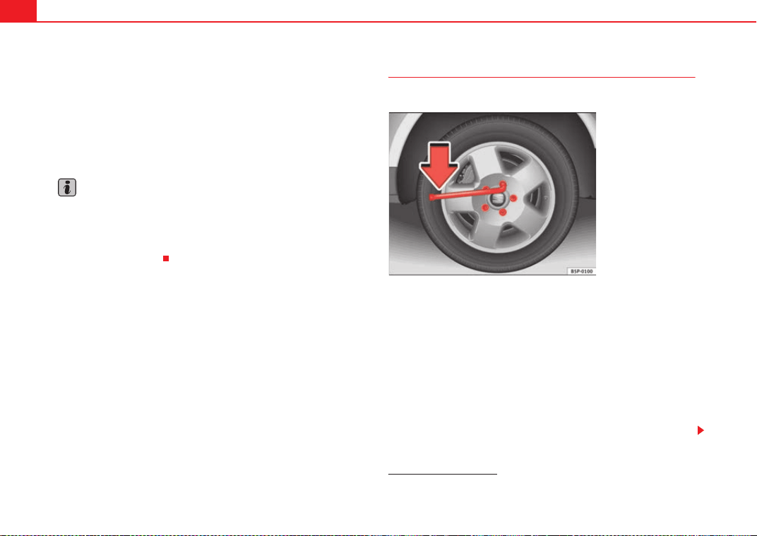
If and when258
–The inflation pressure of the newly fitted spare tyre must be
checked as soon as possible.
–Have the tightening torque of the wheel bolts checked as soon
as possible with a torque wrench. It must be 120 Nm (always
when cold)
–Have the flat tyre replaced as quickly as possible.
Note
• If you notice that the wheel bolts are rusty and difficult to turn when
changing a wheel, they must be replaced before having the tightening torque
checked.
• For your safety, drive at moderate speeds until the wheel bolt tightening
torque has been checked.
Loosening and tightening the wheel bolts
The wheel bolts must be loosened before raising the vehicle.
Loosening
–Fit the box spanner as far as it will go over the wheel bolt
4)
.
– Grip the box spanner as close to the end as possible and turn the
wheel bolts about one turn anti-clockwise ⇒ fig. 193 -arrow-.
Tightening
– Fit the box spanner as far as it will go over the wheel bolt
4)
.
– Grip the box spanner as close to the end as possible and tighten
the bolt firmly by turning clockwise.
4)
An adapter is required to unscrew or tighten the anti-theft wheel bolts* ⇒ page 261.
Fig. 193 Changing the
wheel: Loosen the wheel
bolts
ExeoST_EN.book Seite 258 Freitag, 3. September 2010 11:41 11
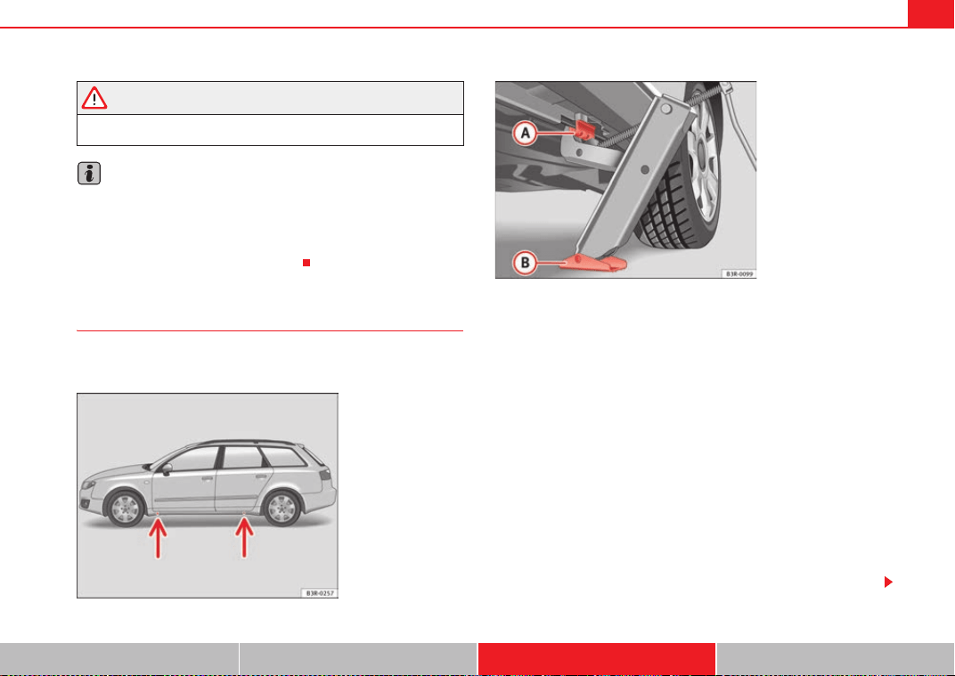
If and when 259
Safety First Operating Instructions Practical Tips Technical Specifications
WARNING
Loosen the wheel bolts only about one turn before raising the vehicle with
the jack. Failure to do so could result in an accident.
Note
• Do not use the hexagonal socket in the screwdriver handle to loosen or
tighten the wheel bolts.
• If the wheel bolt does not come loose, it may be possible to release it by
pushing down the end of the spanner carefully with your foot. Hold on to the
vehicle for support and take care not to slip.
Raising the vehicle
In order to remove the wheel, the vehicle must be raised with
a jack.
– Position the vehicle jack under the door sill at the jacking point
closest to the wheel being changed ⇒ fig. 194 -arrows-.
–Wind up the jack under the jacking point until the claw of the jack
is directly below the vertical rib under the door sill.
– Align the jack so that the arm of the jack fits on the rib under the
door sill ⇒ fig. 195 and the movable base plate of the jack
is flat on the ground.
– Raise the vehicle until the defective wheel is just clear of the
ground.
Recesses at the front and rear of the door sills mark the jacking points
⇒ fig. 194 -arrows-. There is only one jacking point for each wheel. Do not fit
the jack anywhere else.
The distance from the jacking points to the wheel arches is approximately 15
cm at the front and 25 cm at the rear.
Fig. 194 Changing the
wheel: Jack position
points
Fig. 195 Changing the
wheel: Jack
A
A
A
B
ExeoST_EN.book Seite 259 Freitag, 3. September 2010 11:41 11
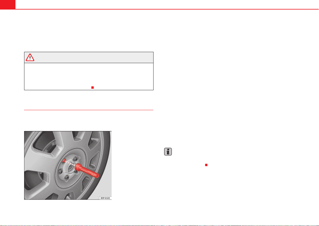
If and when260
An unstable surface under the jack may cause the vehicle to slip off the jack.
Therefore, the jack must be fitted on solid ground offering good support. Use
a large, stable base if necessary. On a hard, slippery surface (such as tiles)
use a rubber mat or similar to prevent the jack from slipping.
WARNING
• Take all precautions so that the base of the jack does not slip. Failure to
do so could result in an accident.
• The vehicle can be damaged if the jack is not applied at the correct
jacking points. There is also a risk of injury since the jack can slip off
suddenly if it is not properly engaged.
Removing and fitting the wheel
For removal and fitting the wheel, the following tasks must be
completed.
After loosening the wheel bolts and raising the vehicle with the jack,
change the wheel as described below:
Removing a wheel
– Unscrew the bolts using the hexagonal tool in the handle of the
screwdriver (vehicle tool) and place them on a clean surface
⇒ fig. 196.
Fitting a wheel
– Screw in the wheel bolts and tighten them lightly using the
hexagonal socket in the screwdriver handle.
The wheel bolts should be clean and easily screwed. Before fitting the spare
wheel, inspect the wheel condition and hub mounting surfaces. These
surfaces must be clean before fitting the wheel.
The hexagonal socket in the screwdriver handle makes it easier to turn the
wheel bolts. The reversible screwdriver blade should be removed when the
tool is used for this purpose.
If tyres with a specific direction of rotation are fitted, note the direction of
rotation.
Note
Do not use the hexagonal socket in the screwdriver handle to loosen or
tighten the wheel bolts.
Fig. 196 Changing the
wheel: Hexagonal socket
in screwdriver handle to
turn the wheel bolts
ExeoST_EN.book Seite 260 Freitag, 3. September 2010 11:41 11
If and when 261
Safety First Operating Instructions Practical Tips Technical Specifications
Anti-theft wheel bolts*
A special adapter is required to turn the anti-theft wheel
bolts.
– Insert the adapter onto the wheel bolt and push it on as far as it
will go ⇒ fig. 197.
– Fit the box spanner as far as it will go over the adapter.
– Loosen or tighten the wheel bolt as appropriate.
Code
The code number of the anti-theft wheel bolt is stamped onto the front part of
the adaptor.
The code number should be noted and kept in a safe place, as it is only by
using the code number that a duplicate adaptor can be obtained from an
Authorised Service Centre.
Tyres with directional tread pattern
Tyres with directional tread pattern must be fitted so that they
rotate in the correct direction.
A directional tread pattern can be identified by arrows on the sidewall that
point in the direction of rotation. Always note the direction of rotation indi-
cated when fitting the wheel. This is important so that these tyres can give
maximum grip and avoid excessive noise, tread wear and aquaplaning.
If, in an emergency, you have to fit the spare wheel so it rotates in the wrong
direction, you must drive extremely carefully. The tyre will not give optimum
performance. This is particularly important when driving on wet roads.
To benefit from the advantages of tyres with this type of tread pattern, the
defective tyre should be replaced as soon as possible so that all tyres again
rotate in the correct direction.
Fig. 197 Anti-theft wheel
bolt
ExeoST_EN.book Seite 261 Freitag, 3. September 2010 11:41 11
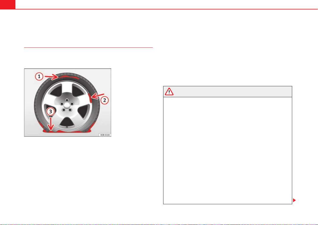
If and when262
Tyre repairs* (Tyre Mobility System)
General information and safety notes
Repaired tyres are only suitable for temporary use over a
short period.
Your vehicle is equipped with a tyre repair kit: the Tyre Mobility System.
In the event of a puncture you will find the TMS, which consists of a sealing
compound and a compressor, located under the floor panel in the luggage
compartment.
The Tyre Mobility System will reliably seal tyres damaged by foreign bodies,
provided that the cuts or punctures are no larger than approx. 4 mm in diam-
eter.
It is not necessary to remove the foreign body from the tyre.
The sealing compound must not be used in the following cases:
• On cuts and punctures larger than 4 mm ⇒ fig. 198
• If the wheel rim has been damaged
• If you have been driving with very low pressure or a completely flat tyre
How to use the TMS (tyre mobility system) is described in the section
Repairing a tyre ⇒ page 263 and in the instructions supplied with the tyre
sealant can.
The TMS (tyre mobility system) can be used at outside temperatures down to
-20 °C.
WARNING
After repairing a tyre please note the following points:
• Do not drive faster than 80 km/h.
• Avoid heavy acceleration, hard braking and fast cornering.
• Vehicle handling could be impaired.
• Tyres which have been sealed using the Tyre Mobility System are only
suitable for temporary use over a short period.
• After using the tyre sealant the tyre pressure monitoring system* may
malfunction. Therefore, please drive carefully to the next available quali-
fied workshop.
• The Tyre Mobility System must NOT be used,
− on cuts and punctures larger than 4 mm
− if the wheel rim has been damaged
− if you have been driving with very low pressure or a completely flat
tyre
• Seek professional assistance if the repair of a tyre puncture is not
possible with the sealing compound.
• Do not allow the sealant to come into contact with your eyes, skin or
clothing.
Fig. 198 The Tyre
Mobility System is not
suitable for repairing this
type of damage to tyres.
A
1
A
2
A
3
ExeoST_EN.book Seite 262 Freitag, 3. September 2010 11:41 11
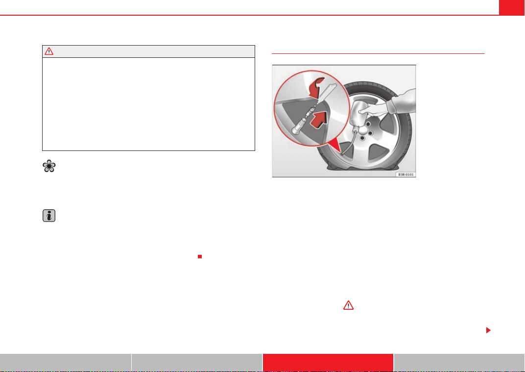
If and when 263
Safety First Operating Instructions Practical Tips Technical Specifications
• If you do come into contact with the sealant immediately rinse the eyes
or skin affected with clean water.
• Change clothing immediately if it becomes soiled with the tyre sealant.
• Make sure you do not breathe in the fumes!
• If any of the tyre sealant is accidentally ingested, immediately rinse the
mouth thoroughly and drink lots of water.
− Do not induce vomiting. Seek medical assistance if needed.
• If any allergic reactions should occur get medical help immediately.
• Keep the sealant away from children.
For the sake of the environment
If you have to dispose of a sealant can, go to a specialised waste service or to
a SEAT Technical Service, where the product can be recycled in an appropriate
waste container.
Note
• If sealant should leak out, leave it to dry. When it has dried, you can pull
it off like a piece of foil.
• Observe the expiry date stated on the sealing compound can. Have the
sealing compound exchanged by a qualified workshop.
Repairing a tyre
Preparations
– If you have a flat tyre or puncture, park the vehicle as far away
from the flow of traffic as possible.
–Apply the handbrake firmly to prevent the vehicle from moving
accidentally on slopes.
– Engage 1st gear.
– Check whether a repair is possible using the Tyre Mobility System
⇒ page 262.
– Ensure that all passengers leave the vehicle and move away from
the danger area ⇒ .
–Take the tyre sealant can and the compressor out of the luggage
compartment.
WARNING (continued)
Fig. 199 Repairing a tyre
ExeoST_EN.book Seite 263 Freitag, 3. September 2010 11:41 11
If and when264
– Stick the “max. 80 km/h” adhesive, which is included with the
tyre sealant can, onto the instrument panel where the driver will
see it.
Filling the tyre
– Shake the tyre sealant can well.
– Screw the enclosed filling hose onto the sealant can as far as it
will go. This will automatically pierce the foil sealing the can.
– Take the valve cap off the tyre valve and use the enclosed valve
insert tool to unscrew the valve insert ⇒ page 263, fig. 199.
– Place the valve insert onto a clean surface.
– Remove the sealing plug from the filling hose and insert the hose
into the tyre valve.
– Hold the tyre sealant can upside down and fill the complete
contents of the can into the tyre.
– Then disconnect the hose and screw the valve insert firmly back
into the tyre valve.
Inflating the tyre
– Screw the compressor filling hose onto the tyre valve and plug
the connector into the cigarette lighter.
– Pump the tyre up to 2.0 to 2.5 bar and monitor the pressure
shown on the pressure gauge.
– If the tyre pressure remains lower than the value specified above
drive the vehicle approx. 10 metres forwards or backwards, so
that the sealant can spread evenly in the tyre. If the pressure is
still lower than the specification the tyre is too badly damaged
and cannot be repaired using the tyre sealant.
Final check
– After about 10 minutes, stop to check the tyre pressure.
– If tyre pressure is less than 1.3 bar, the tyre is too badly
damaged. Do not drive on! You should obtain professional
assistance.
WARNING
• If you have a puncture in heavy traffic, switch on the hazard warning
lights and place the warning triangle in a visible location. This is for your
own safety and also warns other road users.
• Make sure your passengers wait in a safe place (for instance behind the
roadside crash barrier).
• Please observe the manufacturer's safety notes on the compressor and
the instructions supplied with the tyre sealant can.
• If it is not possible to build up a tyre pressure of 2.0 bar within 6
minutes this means that the tyre is too badly damaged. Do not drive on!
• Seek professional assistance if the repair of a tyre puncture is not
possible with the sealing compound.
• If tyre pressure is less than 1.3 bar after driving about 10 minutes, the
tyre is too badly damaged. Do not drive on! Obtain technical assistance.
Caution
Take special care if you have to repair a tyre on a slope.
ExeoST_EN.book Seite 264 Freitag, 3. September 2010 11:41 11
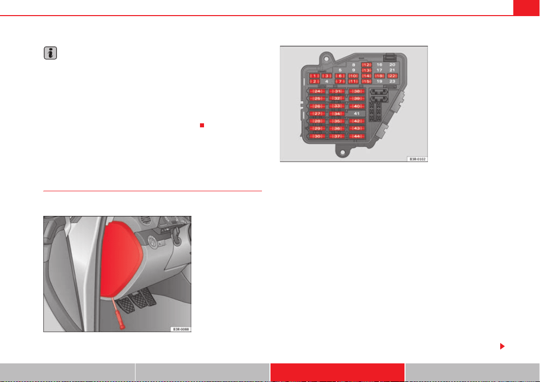
If and when 265
Safety First Operating Instructions Practical Tips Technical Specifications
Note
• Do not use the compressor for longer than 6 minutes. Otherwise, it might
overheat. When the compressor has cooled down, you can use it again.
• If tyre sealant should leak out, leave it to dry and then pull it off like foil.
• After carrying out a tyre repair remember to buy a new tyre sealant can at
a qualified workshop. This will ensure that the Tyre Mobility System is opera-
tive again.
• Please observe legal requirements when doing so.
Fuses
Changing fuses
If a fuse has blown, it must be replaced.
– Switch off the ignition and its failed electrical component.
– Remove the fuse cover using a screwdriver ⇒ fig. 200.
– Identify the fuse corresponding to the damaged electric
consumer ⇒ page 266, “Fuse assignment”.
– Take the plastic clip from inside the fuse cover, fit it onto the
blown fuse, and pull the fuse out.
– Replace the blown fuse (which will have a melted metal strip)
with a new fuse of the same amp rating.
–Fit the fuse cover back on.
The individual electrical circuits are protected by fuses. The fuses are located
behind a cover at the left-hand end of the dash panel.
Two spare fuses and a sticker identifying the fuses are provided on the inside
of the fuse cover. There is also a crank handle for operating the sunroof* by
hand (if the electrical system fails).
Fig. 200 Left side of dash
panel: Fuse box cover
Fig. 201 Schematic
drawing of fuse box at the
left-hand end of dash
panel: Fuses (without fuse
cover)
ExeoST_EN.book Seite 265 Freitag, 3. September 2010 11:41 11
If and when266
Caution
Never “repair” damaged fuses and never replace them with fuses with a
higher rating. Failure to comply could result in fire. It could also cause
damage to other parts of the electrical system.
Note
If a newly replaced fuse blows again after a short time, the electrical system
must be checked by a qualified workshop as soon as possible.
Fuse assignment
This list shows the fuses which can be replaced relatively
easily by the owner.
No. Consumer Amps
1 Air conditioner 10
2 Footwell lamps 5
3 Heated washer jets 5
4 Radiator fan 5
5 Parking aid, automatic gearbox 10
6 Air conditioner (air purity sensor), pressure sensor 5
7
Electronic Stability Programme (ESP), brake light
switch, clutch pedal switch, steering angle sensor
10
8 Telephone 5
9 Vacant
10 Adaptive headlights right 5
11
Airbag and disconnection of the front passenger air-
bag
5
12 Diagnostic socket 10
13 Steering column unit 10
14 Brake lights 10
15 Instrument panel 10
16 Vacant
17 Tyre pressure control, rain/light sensor 10
18 Adaptive headlights left 5
19 Vacant
20 Vacant
21 Vacant
22 Driver door / front passenger door 15
23 Rear doors 15
24 Central electrics unit for convenience equipment 20
25 Heater blower 30
26 Rear window heater 30
27 Power socket for trailer (control unit) 30
28 Fuel pump, auxiliary pump for diesel 20
29 Vacant
30 Sliding/tilting sunroof 20
31
Diagnosis connection, automatic anti-dazzle interior
mirror, reverse light, automatic gearbox
15
32 Towing socket 15
No. Consumer Amps
ExeoST_EN.book Seite 266 Freitag, 3. September 2010 11:41 11
If and when 267
Safety First Operating Instructions Practical Tips Technical Specifications
Some of the electrical items listed in the table are only fitted on certain
models or are optional extras.
The electric windows and electric seat adjusters are protected by circuit
breakers. These reset automatically after a few seconds when the overload
(caused for example by frozen windows) has been corrected.
Note
Please note that the above list contains all data at the time of going to press,
so it is subject to modifications. If discrepancies should occur, please refer to
the sticker on the inside of the fuse cover for the correct information for your
model.
Bulbs
General information
You can change the following bulbs for exterior lights yourself:
• Main headlights: all bulbs (except xenon headlights)
• Tail lights: all bulbs
• Side turn signal bulb
The following bulbs can only be changed by a qualified workshop:
• Main headlights: Xenon* bulb ⇒ page 274
• Front fog light bulbs
As a rule, you require a certain degree of practical skill to change defective
bulbs. This applies in particular to those bulbs which are only accessible from
the engine compartment.
If in doubt, we recommend that you have defective bulbs changed by a qual-
ified workshop or qualified mechanic.
If you do decide to change bulbs in the engine compartment yourself, be
aware of the safety risks involved ⇒ page 229 ⇒ in “Types of bulbs”.
Changing bulbs. Halogen headlights
Types of bulbs
You must only replace a bulb with a bulb of the same type. The name can be
found on the base of the bulb holder.
33 Lighter 20
34 Lambda probe heater 5
35 Luggage compartment power socket* 20
36 Wiper system 30
37
Pump for windscreen washer and headlight washer
system
30
38 Luggage compartment illumination, alarm 15
39 Radio, amplifier 20
40 Horn 25
41 230 volt socket 30
42 Electronic Stability Programme (ESP) 25
43 Engine management 15
44 Seat heating 35
No. Consumer Amps
ExeoST_EN.book Seite 267 Freitag, 3. September 2010 11:41 11
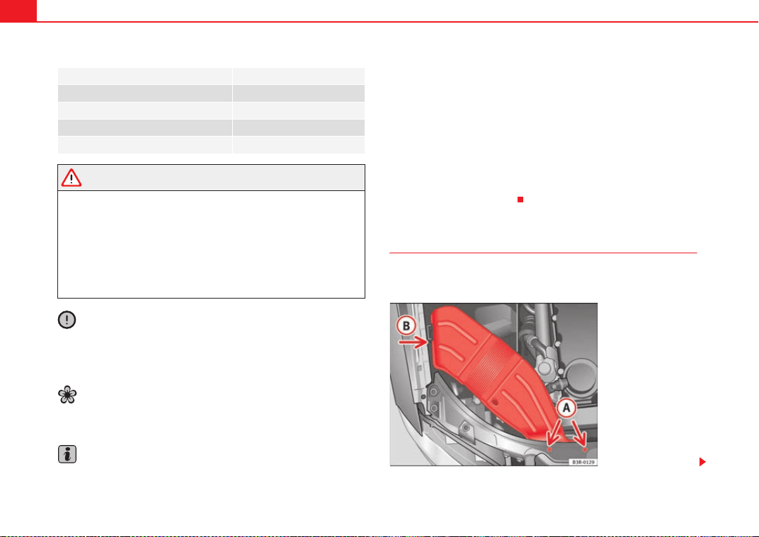
If and when268
WARNING
• Take particular care when working on components in the engine
compartment if the engine is warm - risk of burns!
• Bulbs are highly sensitive to pressure. The glass can break when you
touch the bulb, causing injury.
• The high voltage element of gas discharge bulbs* (xenon light) must be
handled correctly. Otherwise, there is a risk of death.
• When changing bulbs, please take care not to injure yourself on sharp
parts in the headlight housing.
Caution
• Remove the ignition key before working on the electric system. If not, a
short circuit could occur.
• Switch off the lights or parking lights before you change a bulb.
For the sake of the environment
Please ask your specialist retailer how to dispose of used bulbs in the proper
manner.
Note
• Depending on weather conditions (cold or wet), the front lights, the fog
lights, the tail lights and the turn signals may be temporarily misted. This has
no influence on the useful life of the lighting system. By switching on the
lights, the area through which the beam of light is projected will quickly be
demisted. However, the edges may continue to be misted.
• Please check at regular intervals that all lighting (especially the exterior
lighting) on your vehicle is functioning properly. This is not only in the interest
of your own safety, but also in that of all other road users.
• Before changing a bulb, make sure you have the correct new bulb.
• Do not touch the glass part of the bulb with your bare hands, use a cloth
or paper towel instead. Otherwise, the fingerprints left on the glass will
vaporise as a result of the heat generated by the bulb, be deposited on the
reflector and impair its surface.
Removing the air duct
The air duct has to be removed to gain access to the bulbs for
the right-side headlight.
Bulb Type
Dipped beam headlights (halogen) 12 V/55 W (H7 LL)
Main beam headlights 12 V/55 W (H1)
Turn signal 12 V/21 W (PY21W)
Side lights 12 V/5 W (W5W LL)
Fig. 202 Air duct on right
side of vehicle
ExeoST_EN.book Seite 268 Freitag, 3. September 2010 11:41 11
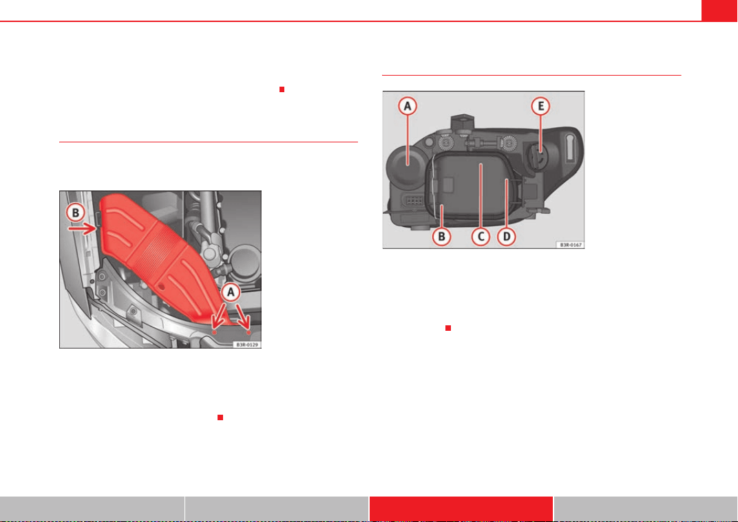
If and when 269
Safety First Operating Instructions Practical Tips Technical Specifications
–Unscrew bolts ⇒ page 268, fig. 202.
– Detach air duct from guide and take it out.
Fitting the air duct
Once the bulb(s) for the right-side headlight have been
changed, the air duct must be re-installed.
– Place the air duct in the correct position.
– First turn the two screws in lightly, then tighten both screws.
– Push the air duct into guide .
Halogen headlight bulbs
Main beam headlights
Side lights
Dipped beam headlights
Side lights
Turn signal
A
A
A
B
Fig. 203 Air duct on right
side of vehicle
A
A
A
B
Fig. 204 Halogen bulbs
A
A
A
B
A
C
A
D
A
E
ExeoST_EN.book Seite 269 Freitag, 3. September 2010 11:41 11
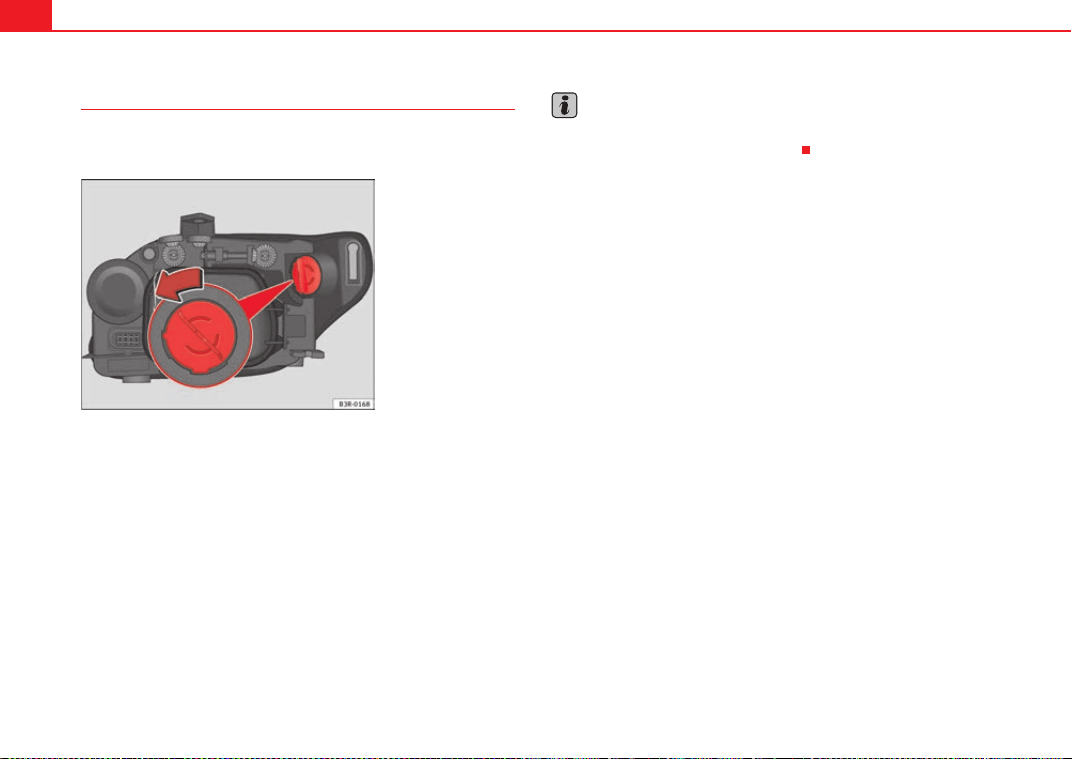
If and when270
Changing the turn signal bulb
The procedure for changing the bulb is the same on both
sides.
– Switch off the ignition and the lights.
– Raise the bonnet.
– Turn the bulb holder anti-clockwise, pulling it by the grip
⇒ fig. 205 and removing the bulb holder and the bulb.
– Replace the blown bulb in the bulb holder (press and turn anti-
clockwise to remove) with a new bulb (press and turn clockwise
to insert).
– Installation is done in the reverse order.
– Check whether the new bulb is working.
Note
Although it is not necessary, previously remove the rigid cover ⇒ page 272,
fig. 208 for easier turn signal bulb changes.
Fig. 205 Turn signal
ExeoST_EN.book Seite 270 Freitag, 3. September 2010 11:41 11
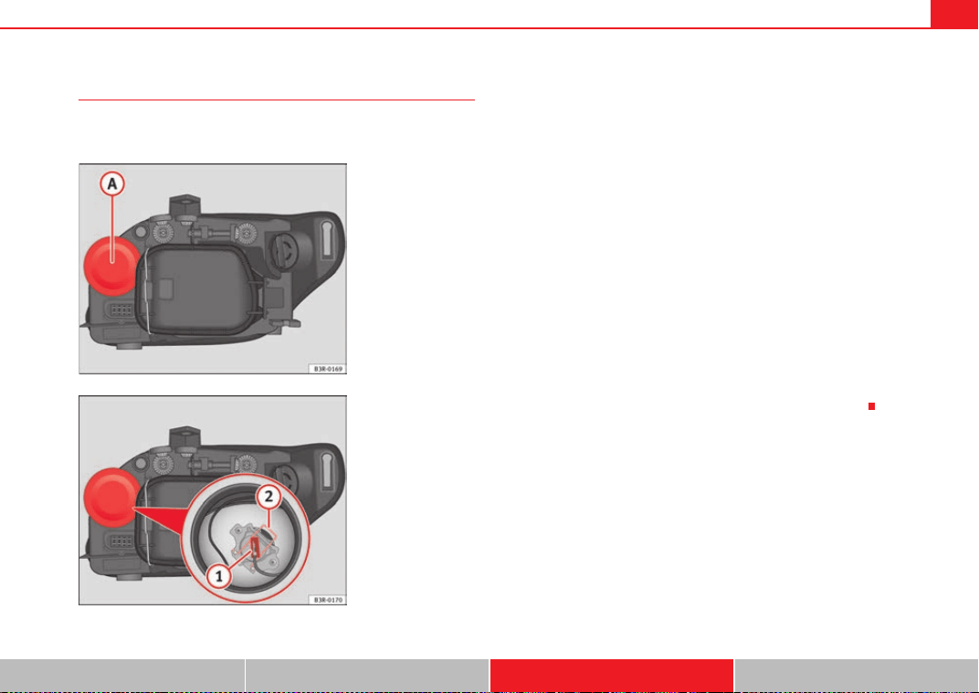
If and when 271
Safety First Operating Instructions Practical Tips Technical Specifications
Changing the main headlight bulb
The procedure for changing the bulb is the same on both
sides.
– Switch off the ignition and the lights.
– Raise the bonnet.
– Pull up on the rubber cover ⇒ fig. 206 to remove it.
– Remove the connector ⇒ fig. 207 from the bulb.
– Press the spring ⇒ fig. 207 inwards and to the right.
– Remove the bulb. pulling it from the connection terminal and
fitting fit the replacement so that it sits correctly in the cut-out on
the reflector. To ensure correct lighting, the filament must be
vertical. When changing the bulb, you can check the position of
the bulb through the headlight glass.
– Installation is in reverse order, ensuring that the rubber cover is
well fitted to the housing.
– Check whether the new bulb is working.
– Have the headlight settings checked as soon as possible.
Fig. 206 Main beam
headlights
Fig. 207 Main beam
headlights
A
A
A
1
A
2
ExeoST_EN.book Seite 271 Freitag, 3. September 2010 11:41 11
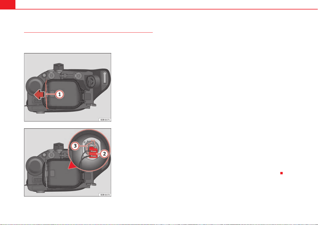
If and when272
Changing the dipped beam headlight bulb
The procedure for changing the bulb is the same on both
sides.
– Switch off the ignition and the lights.
– Raise the bonnet.
– Move the brace ⇒ fig. 208 in the direction of the arrow and
remove the rigid cover, separating the brace side and then
removing the two tabs from the other end of the cover.
– Pull the connector ⇒ fig. 209 from the bulb.
– Unclip the retainer spring ⇒ fig. 209 pressing inwards to the
right.
– Remove the bulb and fit the new one in the headlight casing with
the tab upwards, starting to position it from below.
– Clip on the spring, raising it and pressing it slightly while turning
it anti-clockwise. To ensure correct lighting, the filament must be
vertical. When changing the bulb, you can check the position of
the bulb through the headlight glass.
– Connect the connector to the bulb.
– Fit the cover, first inserting the side tabs and then closing the
cover and the brace. Make sure that the gasket sits well on the
casing cover during the operation.
– Check whether the new bulb is working.
– Have the headlight settings checked as soon as possible.
Fig. 208 Dipped beam
headlights
Fig. 209 Dipped beam
headlights
A
1
A
2
A
3
ExeoST_EN.book Seite 272 Freitag, 3. September 2010 11:41 11
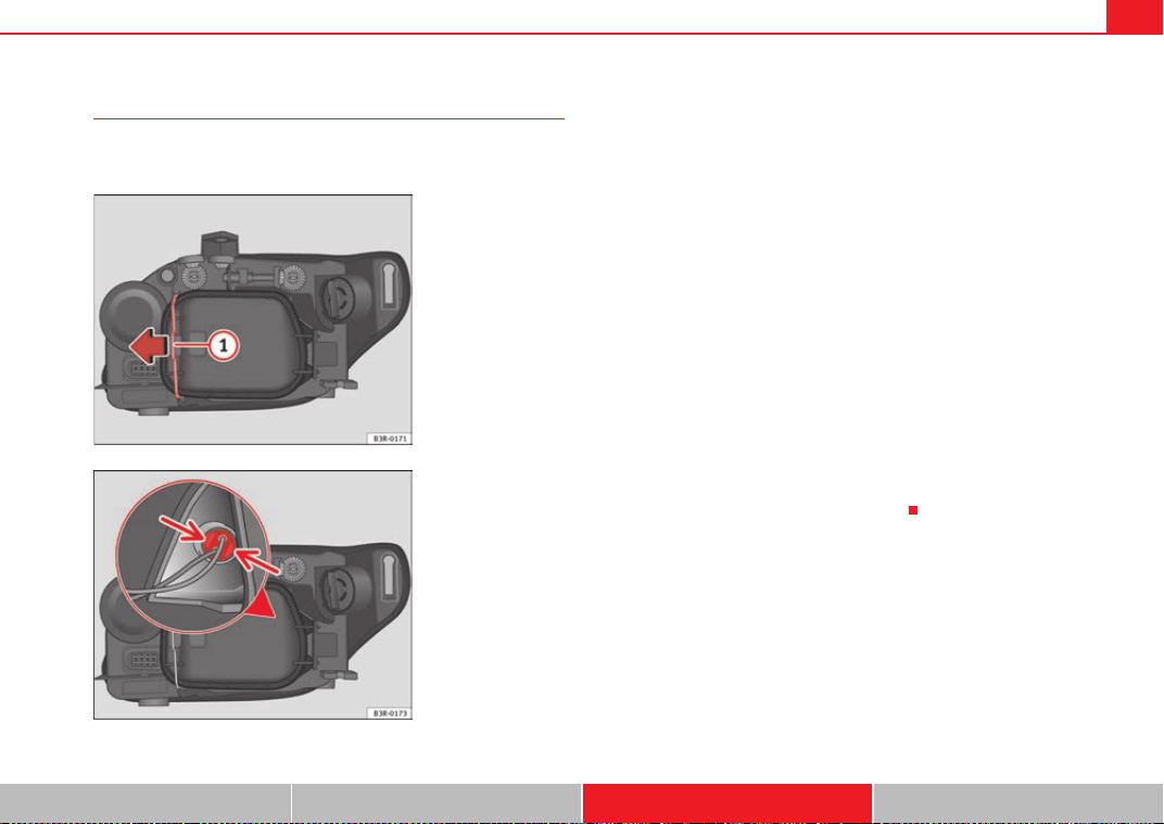
If and when 273
Safety First Operating Instructions Practical Tips Technical Specifications
Changing the side light bulb (outside of vehicle)
The procedure for changing the bulb is the same on both
sides.
– Switch off the ignition and the lights.
– Raise the bonnet.
– Move the brace ⇒ fig. 210 in the direction of the arrow and
remove the rigid cover, separating the brace side and then
removing the two tabs from the other end of the cover.
– Gently press on the bulb holder tabs ⇒ fig. 211 and pull the
cover upwards (it can also be removed by pulling on the bulb
holder wires).
– Separate the bulb from the bulb holder by pulling both pieces
anti-clockwise.
– Fit the new bulb by pressing on the bulb holder.
– Insert the bulb into the socket and press on the bulb holder. Fit
the cover, first inserting the side tabs and then closing the cover
and the brace. Make sure that the gasket sits well on the casing
cover during the operation.
– Check whether the new bulb is working.
Fig. 210 Side light bulb
(outside of vehicle)
Fig. 211 Side light bulb
(outside of vehicle)
A
1
ExeoST_EN.book Seite 273 Freitag, 3. September 2010 11:41 11
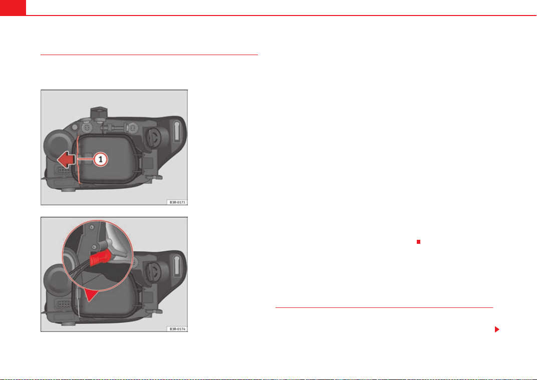
If and when274
Changing the side light bulb (inside of vehicle)
The procedure for changing the bulb is the same on both
sides.
– Switch off the ignition and the lights.
– Raise the bonnet.
– Move the brace ⇒ fig. 212 in the direction of the arrow and
remove the rigid cover, separating the brace side and then
removing the two tabs from the other end of the cover.
– Remove the bulb and the bulb holder by pulling on the bulb
holder wiring.
– Separate the bulb from the bulb holder by pulling both pieces
anti-clockwise.
– Fit the new bulb by pressing on the bulb holder.
– Insert the bulb into the socket so that the side of the bulb holder
grip is vertical ⇒ fig. 213 and press on it.
– Fit the cover, first inserting the side tabs and then closing the
cover and the brace. Make sure that the gasket sits well on the
casing cover during the operation.
– Check whether the new bulb is working.
Changing bulbs. Bi-Xenon AFS headlights
Types of bulbs
You must only replace a bulb with a bulb of the same type. The name can be
found on the base of the bulb holder.
Fig. 212 Side light bulb
(inside of vehicle)
Fig. 213 Side lights. Bulb
holder grip in vertical
position
A
1
ExeoST_EN.book Seite 274 Freitag, 3. September 2010 11:41 11
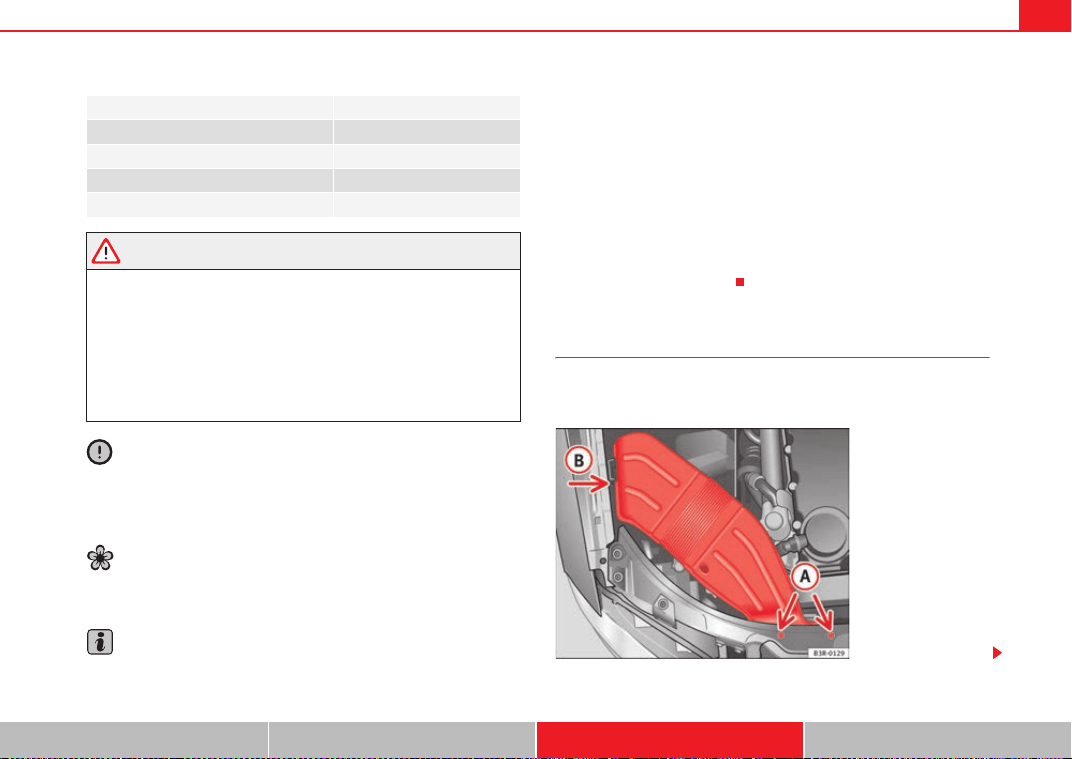
If and when 275
Safety First Operating Instructions Practical Tips Technical Specifications
WARNING
• Take particular care when working on components in the engine
compartment if the engine is warm - risk of burns!
• Bulbs are highly sensitive to pressure. The glass can break when you
touch the bulb, causing injury.
• The high voltage element of gas discharge bulbs* (xenon light) must be
handled correctly. Otherwise, there is a risk of death.
• When changing bulbs, please take care not to injure yourself on sharp
parts in the headlight housing.
Caution
• Remove the ignition key before working on the electric system. If not, a
short circuit could occur.
• Switch off the lights or parking lights before you change a bulb.
For the sake of the environment
Please ask your specialist retailer how to dispose of used bulbs in the proper
manner.
Note
• Depending on weather conditions (cold or wet), the front lights, the fog
lights, the tail lights and the turn signals may be temporarily misted. This has
no influence on the useful life of the lighting system. By switching on the
lights, the area through which the beam of light is projected will quickly be
demisted. However, the edges may continue to be misted.
• Please check at regular intervals that all lighting (especially the exterior
lighting) on your vehicle is functioning properly. This is not only in the interest
of your own safety, but also in that of all other road users.
• Before changing a bulb, make sure you have the correct new bulb.
• Do not touch the glass part of the bulb with your bare hands, use a cloth
or paper towel instead. Otherwise, the fingerprints left on the glass will
vaporise as a result of the heat generated by the bulb, be deposited on the
reflector and impair its surface.
Removing the air duct
The air duct has to be removed to gain access to the bulbs for
the right-side headlight.
Bulb Type
Xenon bulbs 12 V/35 W (D1S)
DRL (day light) 12 V/21 W (P21W SLL)
Turn signal 12 V/21 W (PY21W)
Side lights 12 V/5 W (W5W blue LL)
Fig. 214 Air duct on right
side of vehicle
ExeoST_EN.book Seite 275 Freitag, 3. September 2010 11:41 11
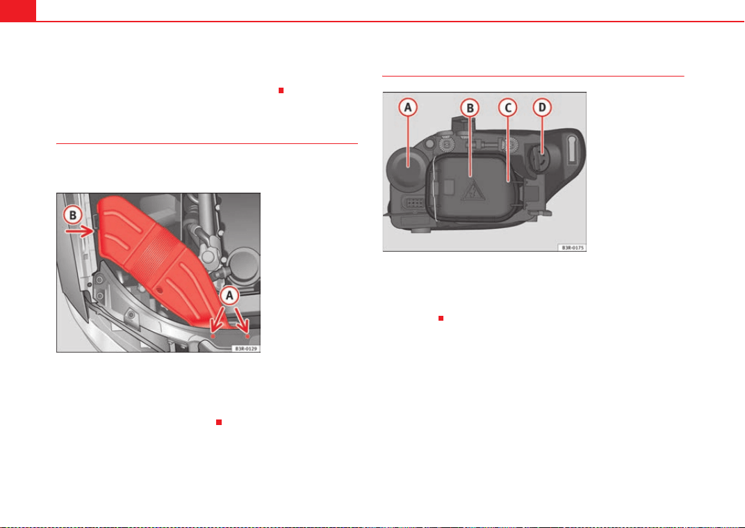
If and when276
–Unscrew bolts ⇒ page 275, fig. 214.
– Detach air duct from guide and take it out.
Fitting the air duct
Once the bulb(s) for the right-side headlight have been
changed, the air duct must be re-installed.
– Place the air duct in the correct position.
– First turn the two screws in lightly, then tighten both screws.
– Push the air duct into guide .
Bi-Xenon AFS headlight bulbs
Turn signal
Xenon headlight (dipped beam/main beam)
Side lights
DRL light
A
A
A
B
Fig. 215 Air duct on right
side of vehicle
A
A
A
B
Fig. 216 Bi-Xenon AFS
headlight bulbs
A
A
A
B
A
C
A
D
ExeoST_EN.book Seite 276 Freitag, 3. September 2010 11:41 11
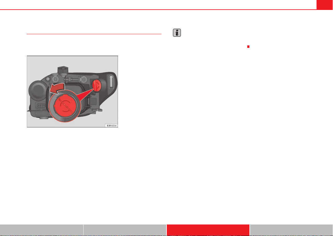
If and when 277
Safety First Operating Instructions Practical Tips Technical Specifications
Changing the DRL light bulb (daytime running light)
The procedure for changing the bulb is the same on both
sides.
– Switch off the ignition and the lights.
– Raise the bonnet.
– Turn the bulb holder anti-clockwise, pulling it by the grip
⇒ fig. 217 and removing the bulb holder and the bulb.
– Replace the blown bulb in the bulb holder (press and turn anti-
clockwise to remove) with a new bulb (press and turn clockwise
to insert).
– Installation is done in the reverse order.
Note
Although it is not necessary, previously remove the rigid cover ⇒ page 279,
fig. 220 for easier day light bulb changes.
Fig. 217 DRL light
ExeoST_EN.book Seite 277 Freitag, 3. September 2010 11:41 11
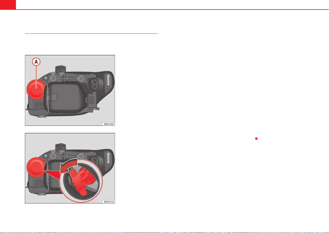
If and when278
Changing the turn signal bulb
The procedure for changing the bulb is the same on both
sides.
– Switch off the ignition and the lights.
– Raise the bonnet.
– Pull the rubber cap ⇒ fig. 218 to remove it.
– Remove the bulb holder by pulling on the grip and turning it anti-
clockwise ⇒ fig. 219.
– Replace the blown bulb in the bulb holder (press and turn anti-
clockwise to remove) with a new bulb (press and turn clockwise
to insert).
– Insert the bulb holder into the socket with the tab facing upwards
and the grip horizontal. Press it against the socket and turn
clockwise. When changing the bulb, you can check the position
of the bulb through the headlight glass.
– Fit the rubber cap and tighten, making sure it fit properly into the
headlight casing.
– Check whether the new bulb is working.
Fig. 218 Turn signal
Fig. 219 Turn signal
ExeoST_EN.book Seite 278 Freitag, 3. September 2010 11:41 11

If and when 279
Safety First Operating Instructions Practical Tips Technical Specifications
Changing the side light bulb
The procedure for changing the bulb is the same on both
sides.
– Switch off the ignition and the lights.
– Raise the bonnet.
– Move the brace ⇒ fig. 220 in the direction of the arrow and
remove the rigid cover, separating the brace side and then
removing the two tabs from the other end of the cover.
– Remove the bulb holder by pulling on the grip ⇒ fig. 221 (it can
also be removed by pulling on the bulb holder wires).
– Separate the bulb from the bulb holder by pulling both pieces
anti-clockwise.
– Fit the new bulb by pressing on the bulb holder.
– Insert the bulb into the socket and press on the bulb holder grip.
– Fit the cover, first inserting the side tabs and then closing the
cover and the brace. Make sure that the gasket sits well on the
casing cover during the operation.
– Check whether the new bulb is working.
Changing the xenon bulb
The procedure for changing the bulb is the same on both sides.
WARNING
This type of bulb should be changed at a qualified workshop.
Fig. 220 Side light
Fig. 221 Side light
A
1
ExeoST_EN.book Seite 279 Freitag, 3. September 2010 11:41 11
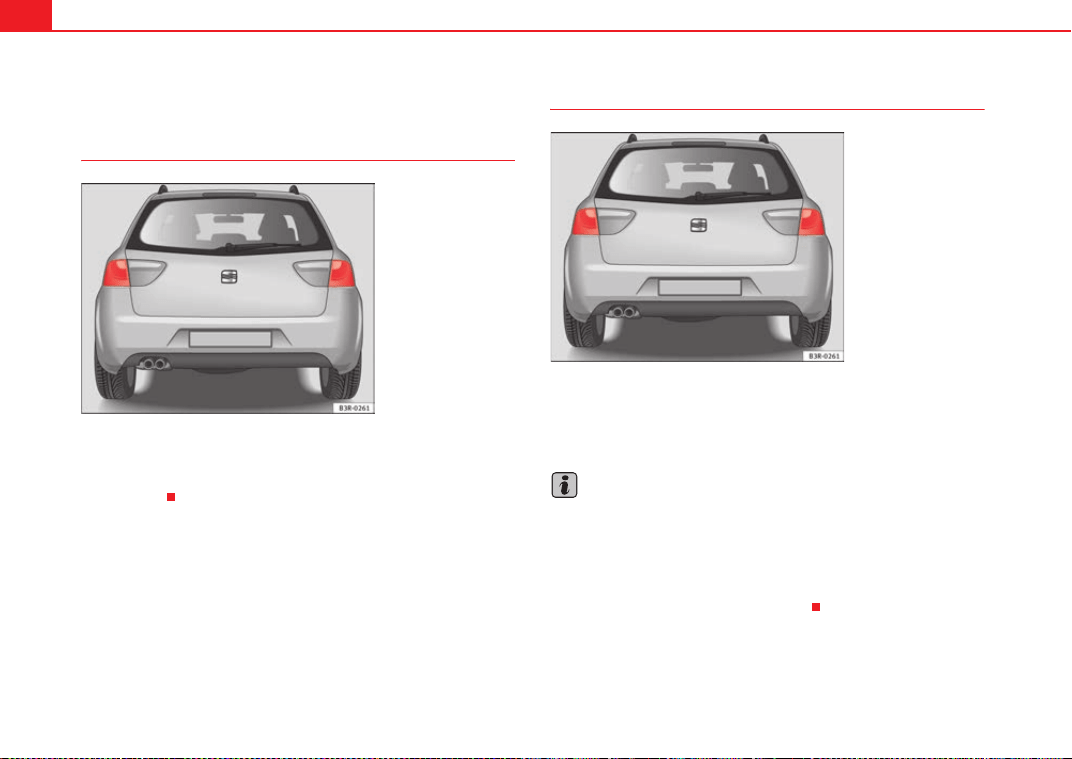
If and when280
Changing tail light bulbs (on side panel)
Overview of tail lights
Tail lights on side panel
• Brake lights and side lights
• Turn signal
Overview of tail lights. LED lamps
Tail lights on side panel
• Brake lights and side lights
• Turn signal
Note
• It is only possible to change the turn signal light.
• If the warning lamp for the brake light or side light (LED lamp) lights up,
the tail light assembly should be replaced.
• The failure of the lamp is only shown when the LED function goes out
completely. Sometimes, a LED will stop working, without displaying the
warning as the function continues to operate.
Fig. 222 Overview of tail
lights
Fig. 223 Overview of tail
lights
ExeoST_EN.book Seite 280 Freitag, 3. September 2010 11:41 11
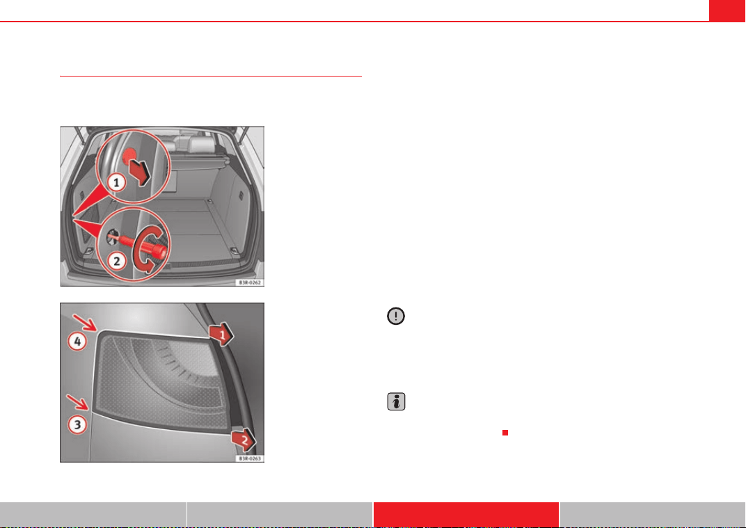
If and when 281
Safety First Operating Instructions Practical Tips Technical Specifications
Removing the tail light
To change the bulbs you must remove the tail light assembly.
Removing the light requires a certain degree of practical skill.
A special retaining screw is used to secure and guide the tail light.
– Check which of the bulbs is defective.
–Open the tailgate.
– Take the screwdriver out of the vehicle's tool kit ⇒ page 254.
– Use the flat-blade side of the reversible screwdriver insert.
– Prise off the cover with a screwdriver in the slot ⇒ fig. 224
and remove the cover (with the retaining clips) from the opening.
– Carefully loosen the screw located behind the cover with the
screwdriver, turning it anti-clockwise (arrows) .
– Gradually ease the tail light out of the housing (⇒ fig. 225 posi-
tions and ) by pulling alternately in positions and .
– Remove the bulb holder ⇒ page 282.
Caution
When removing or installing the tail light, take care not to cause any damage.
• Removing the tail light in particular can lead to the paintwork or tail light
becoming damaged. This is another reason why we recommend having the
bulbs changed by a qualified workshop.
Note
Make sure you have a soft cloth ready to place under the glass on the tail
light, to avoid any scratches.
Fig. 224 Luggage
compartment: Location of
the bolt securing the tail
light unit
Fig. 225 Removing tail
light from side panel
A
1
A
2
A
3
A
4
A
1
A
2
ExeoST_EN.book Seite 281 Freitag, 3. September 2010 11:41 11
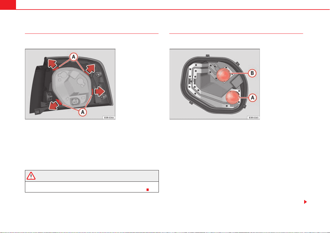
If and when282
Remove the bulb holder
When changing a bulb, you must first remove the bulb holder.
There are four securing tabs on the inside of the tail light unit.
– Release the retaining tabs ⇒ fig. 226.
– Lift out the bulb holder in the direction of the arrow .
– Change the defective bulb ⇒ page 282 ⇒ page 283.
WARNING
If a bulb is replaced in a tail light assembly with LED, do not pull too hard
on the bulb holder to avoid damaging the wiring of the LED module.
Changing bulbs
All bulbs can be changed easily in the bulb holder.
The bulbs are secured with a bayonet fastener. The table below
gives an overview of the bulb positions.
– Lightly press the defective bulb into the bulb holder, then turn it
to the left and remove it.
– Fit the new bulb, pressing it into the bulb holder and turn it to the
right as far as it will go.
– Use a cloth to remove any fingerprints from the glass part of the
bulb.
– Check whether the new bulb is working.
– Re-install the bulb holder ⇒ page 283.
Fig. 226 Retaining tabs
on reverse side of tail light
A
A
A
B
Fig. 227 Position of the
bulbs in the bulb holder:
Example: Outer left tail
light
ExeoST_EN.book Seite 282 Freitag, 3. September 2010 11:41 11
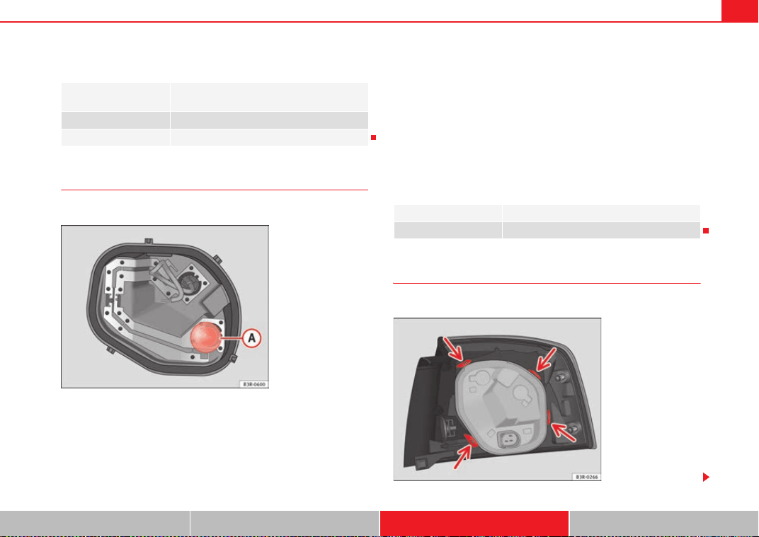
If and when 283
Safety First Operating Instructions Practical Tips Technical Specifications
Position of the bulbs
Changing bulbs. LED lamps
All bulbs can be changed easily in the bulb holder.
The bulb is secured with a bayonet fastening. The table below gives
an overview of the bulb positions.
– Lightly press the defective bulb into the bulb holder, then turn it
to the left and remove it.
– Fit the new bulb, pressing it into the bulb holder and turn it to the
right as far as it will go.
– Use a cloth to remove any fingerprints from the glass part of the
bulb.
– Check whether the new bulb is working.
– Re-install the bulb holder ⇒ page 283.
Position of the bulbs
Fitting the bulb holder
The bulb holder is easy to fit.
Pos. ⇒ page 282,
fig. 227
Bulb function
A Turn signal
B Brake lights and side lights
Fig. 228 Position of the
bulbs in the bulb holder:
Example: Outer left tail
light
Pos. ⇒ fig. 228 Bulb function
A Turn signal
Fig. 229 Securing the
bulb holder in the tail
light unit
ExeoST_EN.book Seite 283 Freitag, 3. September 2010 11:41 11
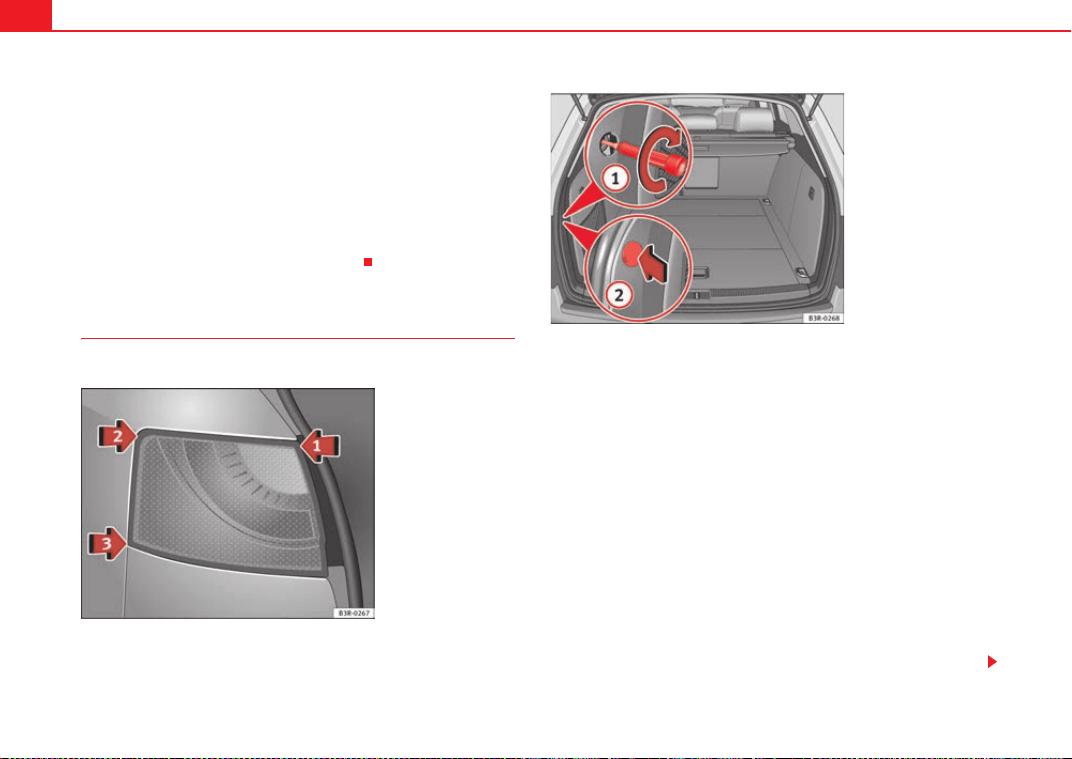
If and when284
– Check that the seal is seated correctly on the bulb holder.
– Position the bulb holder on the tail light and align it so that it is
securely seated.
– Press the bulb holder into the tail light until it engages.
– Check that all four retaining tabs ⇒ page 283, fig. 229 -arrows-
have engaged.
– Re-install the tail light unit ⇒ page 284.
Fitting the tail light unit
The tail light unit is easy to fit.
– First place the tail light unit in ⇒ fig. 230 arrow in the
housing.
– Gently press the tail light unit against the housing, first in posi-
tion and then in position , until that the clips engage firmly
in the rubber mountings.
– Apply gentle pressure to the front side of the tail light unit and
secure using the screwdriver, from the luggage compartment
⇒ fig. 231 .
– Try to move the tail light sideways to ensure it is correctly fitted.
– Fit the cover back onto the screw, with the notch pointing to the
rear .
– Put the screwdriver back into the tool kit.
– Make sure that all bulbs for the tail lights are working.
Fig. 230 Fitting the tail
light unit
Fig. 231 Luggage
compartment: Location of
the bolt securing the tail
light unit
A
1
A
2
A
3
A
1
A
2
ExeoST_EN.book Seite 284 Freitag, 3. September 2010 11:41 11
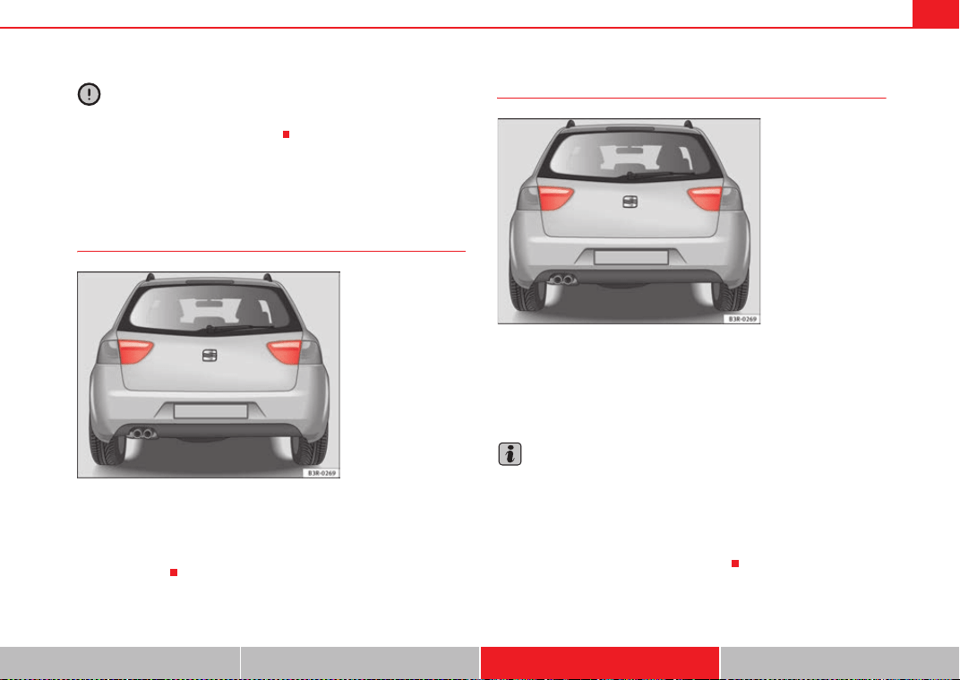
If and when 285
Safety First Operating Instructions Practical Tips Technical Specifications
Caution
Take care when fitting the tail light unit to make sure there is no damage to
the paintwork or any of its components.
Changing tail light bulbs (on tailgate)
Overview of tail lights
Tail lights on the tailgate
• Rear side lights
• Rear fog light
• Reverse lights
Overview of tail lights. LED lamps
Tail lights on the tailgate
• Rear side lights
• Rear fog light
• Reverse lights
Note
• It is only possible to replace the rear fog lamp and the reversing light.
• If the warning lamp for the side light (LED lamp) lights up, the tail light
assembly should be replaced.
• The failure of the lamp is only shown when the LED function goes out
completely. Sometimes, a LED will stop working, without displaying the
warning as the function continues to operate.
Fig. 232 Overview of tail
lights
Fig. 233 Overview of tail
lights
ExeoST_EN.book Seite 285 Freitag, 3. September 2010 11:41 11
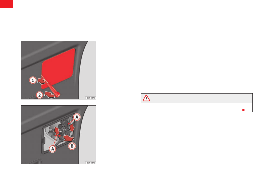
If and when286
Remove the bulb holder
The tailgate must be open to change the bulbs.
You can access the bulb holder for the inner tail lights via the inside
of the tailgate.
– Check which of the bulbs is defective.
– Take the screwdriver out of the vehicle's tool kit ⇒ page 254.
– Insert the screwdriver into the opening in the cover ⇒ fig. 234
and detach the cover .
– Press on the tabs ⇒ fig. 235 in the direction of the arrows
and remove the bulb holder by pulling in the direction of the
arrow .
– Change the bulbs ⇒ page 287 ⇒ page 287.
WARNING
If a bulb is replaced in a tail light assembly with LED, do not pull too hard
on the bulb holder to avoid damaging the wiring of the LED module.
Fig. 234 Remove the
cover of the tailgate trim
Fig. 235 Remove the bulb
holder
A
1
A
2
A
A
A
B
ExeoST_EN.book Seite 286 Freitag, 3. September 2010 11:41 11
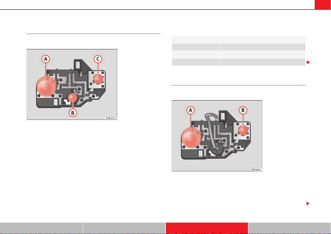
If and when 287
Safety First Operating Instructions Practical Tips Technical Specifications
Changing bulbs
All bulbs can be changed easily in the bulb holder.
The bulbs are secured with a bayonet fastener. The table below
gives an overview of the bulb positions.
– Lightly press the defective bulb into the bulb holder, then turn it
to the left and remove it.
– Fit the new bulb, pressing it into the bulb holder and turn it to the
right as far as it will go.
– Use a cloth to remove any fingerprints from the glass part of the
bulb.
– Check whether the new bulb is working.
– Re-install the bulb holder ⇒ page 288.
Position of the bulbs
Changing bulbs. LED lamps
All bulbs can be changed easily in the bulb holder.
The bulbs are secured with a bayonet fastener. The table below
gives an overview of the bulb positions.
– Lightly press the defective bulb into the bulb holder, then turn it
to the left and remove it.
Fig. 236 Position of the
bulbs in the bulb holder.
Example: Tail lights on the
tailgate
Pos. ⇒ fig. 236 Bulb function
A Reverse lights
B Rear side lights
C Rear fog light
Fig. 237 Position of the
bulbs in the bulb holder.
Example: Tail lights on the
tailgate
ExeoST_EN.book Seite 287 Freitag, 3. September 2010 11:41 11
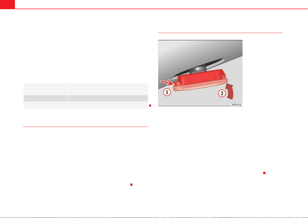
If and when288
– Fit the new bulb, pressing it into the bulb holder and turn it to the
right as far as it will go.
– Use a cloth to remove any fingerprints from the glass part of the
bulb.
– Check whether the new bulb is working.
– Re-install the bulb holder ⇒ page 288.
Position of the bulbs
Fitting the bulb holder
The bulb holder is easy to fit.
– Position the bulb holder on the tail light and align it so that it is
securely seated.
– Press the bulb holder into the tail light until it engages.
– Fit the cover back in the interior trim so that it engages.
– Put the screwdriver back into the tool kit.
– Make sure that all bulbs for the tail lights are working.
Side turn signals
– Press the turn signal to the left or to the right to remove the bulb.
– Remove the bulb holder from the turn signal.
– Remove the failed glass bulb and replace with a new bulb.
– Insert the bulb holder in the turn signal guide until it clicks into
place.
– First place the turn signal in the opening in the bodywork, fixing
the tabs ⇒ fig. 238, arrow .
– Insert the bulb as shown by the arrow ⇒ fig. 238.
Pos. ⇒ page 287,
fig. 236
Bulb function
A Reverse lights
B Rear fog light
Fig. 238 Side turn signal
A
1
A
2
ExeoST_EN.book Seite 288 Freitag, 3. September 2010 11:41 11
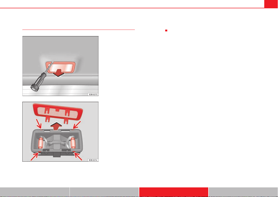
If and when 289
Safety First Operating Instructions Practical Tips Technical Specifications
Luggage compartment lights
– Remove the tulip-shaped fitting by pressing on its inside edge
using the flat side of a screwdriver.
– Remove the protective cover and remove the bulb from the
housing.
Fig. 239 Luggage
compartment light
Fig. 240 Luggage
compartment light
ExeoST_EN.book Seite 289 Freitag, 3. September 2010 11:41 11
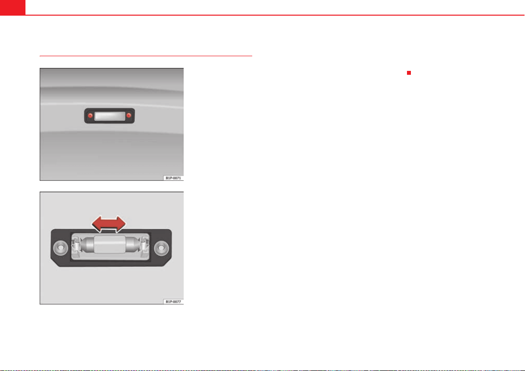
If and when290
Registration light
– To remove the light cover, unscrew the bolts ⇒ fig. 241.
– Remove the bulb, moving it in the direction of the arrow and
outwards ⇒ fig. 242.
– Installation is done in the reverse order.
Fig. 241 Number plate
light
Fig. 242 Number plate
light
ExeoST_EN.book Seite 290 Freitag, 3. September 2010 11:41 11
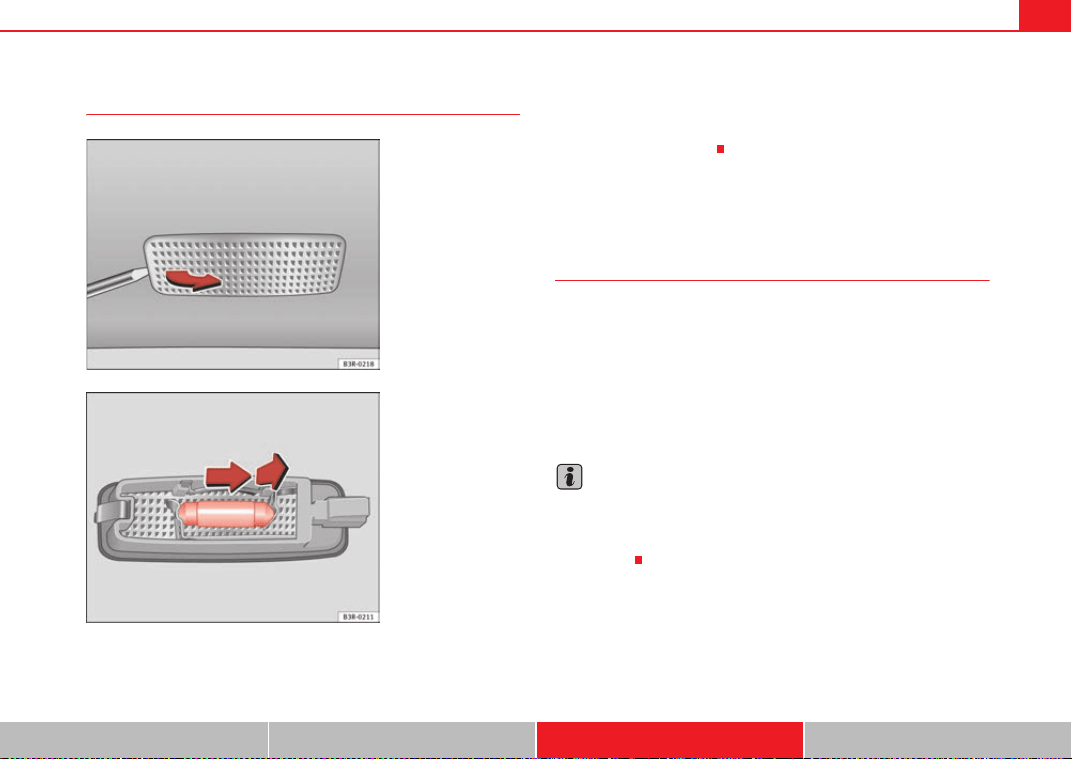
If and when 291
Safety First Operating Instructions Practical Tips Technical Specifications
Sun visor light
– Remove the bulb carefully, using the screwdriver on its flat side
⇒ fig. 243.
– Use a screwdriver to remove the protective cover.
– Remove the bulb, moving it in the direction of the arrow and
outwards ⇒ fig. 244.
Jump-starting
Jump leads
The jump lead must have a sufficient wire cross section.
If the engine fails to start because of a discharged battery, the battery can be
connected to the battery of another vehicle to start the engine.
Jump leads
Jump leads must comply with standard DIN 72553 (see manufacturer's docu-
mentation). The wire cross section must be at least 25 mm
2
for petrol engines
and at least 35 mm
2
for diesel engines.
Note
• The vehicles must not touch each other, otherwise electricity could flow as
soon as the positive terminals are connected.
• The discharged battery must be properly connected to the vehicle elec-
trical system.
Fig. 243 Removing sun
visor light
Fig. 244 Removing sun
visor light
ExeoST_EN.book Seite 291 Freitag, 3. September 2010 11:41 11
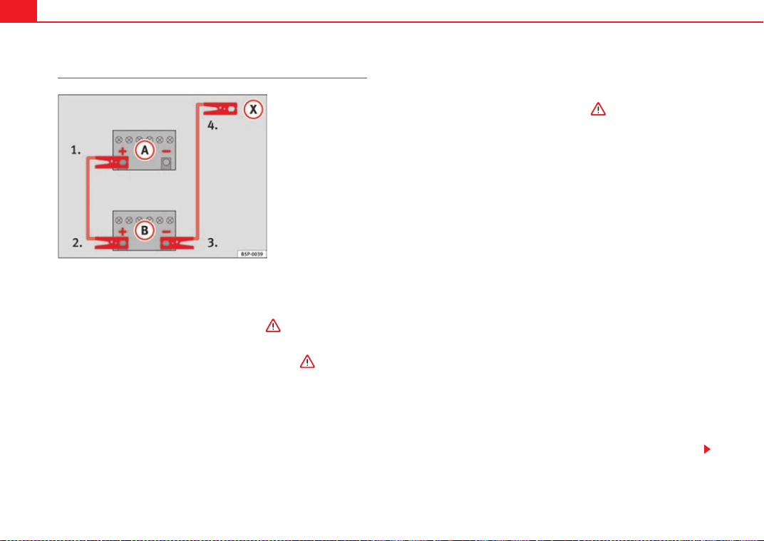
If and when292
How to jump start: description
On ⇒ fig. 245 shows the flat battery and the charged battery.
Jump lead terminal connections
– Switch off the ignition of both vehicles ⇒ .
1. Connect one end of the red jump lead to the positive ⇒ fig. 245
terminal of the vehicle with the flat battery ⇒ .
2. Connect the other end of the red jump lead to the positive
terminal in the vehicle providing assistance.
3. Connect one end of the black jump lead to the negative terminal
on the battery of the vehicle providing assistance.
4. Connect the other end of the black jump lead to a solid metal
component which is bolted on to the engine block, or onto the
engine block itself of the vehicle with the flat battery. Do not
connect it to a point near the battery ⇒ .
5. Position the leads in such a way that they cannot come into
contact with any moving parts in the engine compartment.
Starting
6. Start the engine of the vehicle with the boosting battery and let
it run at idling speed.
7. Start the engine of the vehicle with the flat battery and wait one
or two minutes until the engine is running.
Removing the jump leads
8. Before you remove the jump leads, switch off the headlights (if
they are switched on).
9. Turn on the heater blower and heated rear window in the vehicle
with the flat battery. This helps minimise voltage peaks which are
generated when the leads are disconnected.
10. When the engine is running, disconnect the leads in reverse
order to the details given above.
Connect the battery clamps so they have good metal-to-metal contact with
the battery terminals.
If the engine fails to start, switch off the starter after about 10 seconds and
try again after about half a minute.
Fig. 245 How to connect
the jump leads
A
A
A
B
A
+
A
+
A
-
A
X
ExeoST_EN.book Seite 292 Freitag, 3. September 2010 11:41 11

If and when 293
Safety First Operating Instructions Practical Tips Technical Specifications
WARNING
• Please note the safety warnings referring to working in the engine
compartment ⇒ page 229.
• The battery providing assistance must have the same voltage as the flat
battery (12V) and approximately the same capacity (see imprint on
battery). Failure to comply could result in an explosion.
• Never use jump leads when one of the batteries is frozen. Danger of
explosion! Even after the battery has thawed, battery acid could leak and
cause chemical burns. If a battery freezes, it should be replaced.
• Keep sparks, flames and lighted cigarettes away from batteries, danger
of explosion. Failure to comply could result in an explosion.
• Observe the instructions provided by the manufacturer of the jump
leads.
• Do not connect the negative cable from the other vehicle directly to the
negative terminal of the flat battery. The gas emitted from the battery could
be ignited by sparks. Danger of explosion.
• Do not attach the negative cable from the other vehicle to parts of the
fuel system or to the brake line.
• The non-insulated parts of the battery clamps must not be allowed to
touch. The jump lead attached to the positive battery terminal must not
touch metal parts of the vehicle, this can cause a short circuit.
• Position the leads in such a way that they cannot come into contact
with any moving parts in the engine compartment.
• Do not bend over the batteries. This could result in chemical burns.
Note
The vehicles must not touch each other, otherwise electricity could flow as
soon as the positive terminals are connected.
ExeoST_EN.book Seite 293 Freitag, 3. September 2010 11:41 11
If and when294
Towing and tow-starting
Tow-starting
The use of jump leads is preferable to tow-starting.
We recommend that you do not tow-start your vehicle. Jump-starting
is preferable ⇒ page 291.
However, if your vehicle has to be tow-started:
– Engage the 2nd or the 3rd gear.
– Keep the clutch pressed down.
– Switch the ignition on.
– Once both vehicles are moving, release the clutch.
– As soon as the engine starts, press the clutch and move the gear
lever into neutral. This helps to prevent driving into the towing
vehicle.
WARNING
The risk of accidents is high when tow-starting. The vehicle being towed
can easily collide with the towing vehicle.
Caution
When tow-starting, fuel could enter the catalytic converter and damage it.
General notes
Please observe the following points if you use a tow-rope:
Notes for the driver of the towing vehicle
– Drive slowly at first until the tow-rope is taut. Then accelerate
gradually.
– Begin and change gears cautiously. If you are driving an auto-
matic vehicle, accelerate gently.
– Remember that the brake servo and power steering are not
working in the vehicle you are towing. Brake earlier than you
would normally, but with a more gentle pressure on the brake.
Notes for the driver of the towed vehicle
– Ensure that the tow-rope remains taut at all times when towing.
Tow-rope or tow-bar
It is easier and safer to tow a vehicle with a tow-bar. You should only use a
tow-rope if you do not have a tow-bar.
A tow-rope should be slightly elastic to reduce the loading on both vehicles.
It is advisable to use a tow-rope made of synthetic fibre or similarly elastic
material.
Attach the tow-rope or the tow-bar only to the towing eyes provided or a
towing bracket.
Driving style
Towing requires some experience, especially when using a tow-rope. Both
drivers should be familiar with the technique required for towing. Inexperi-
enced drivers should not attempt to tow-start or tow away another vehicle.
ExeoST_EN.book Seite 294 Freitag, 3. September 2010 11:41 11
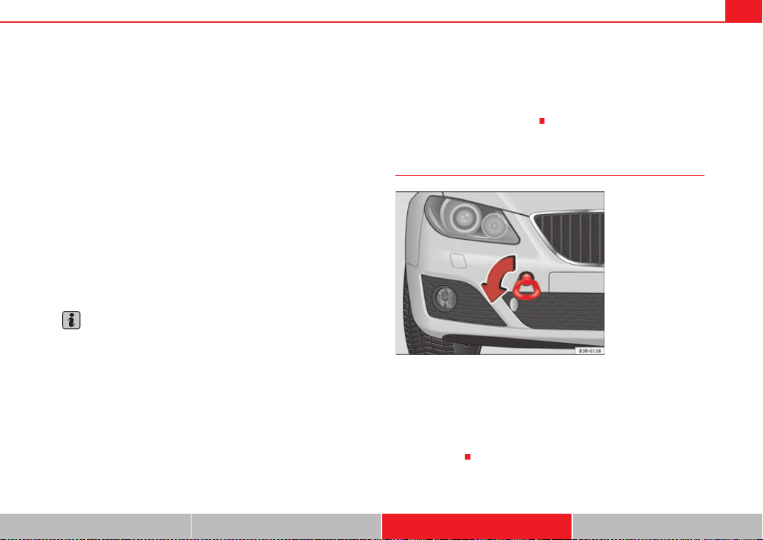
If and when 295
Safety First Operating Instructions Practical Tips Technical Specifications
Do not pull too hard with the towing vehicle and take care to avoid jerking the
tow-rope. When towing on an unpaved road, there is always a risk of over-
loading and damaging the anchorage points.
The ignition of the vehicle being towed must be switched on to prevent the
steering wheel from locking and also to allow the use of the turn signals,
horn, windscreen wipers and washers.
As the brake servo does not work if the engine is not running, you must apply
considerably more pressure to the brake pedal than you normally would.
As the power assisted steering does not work if the engine is not running, you
will need more strength to steer than you normally would.
Towing vehicles with an automatic gearbox
• Put the selector lever into position “N”.
• Do not drive faster than 50 km/h when towing a vehicle.
• Do not tow further than 50 km.
• If a breakdown vehicle is used, the vehicle must be towed with the front
wheels raised.
Note
• Observe legal requirements when towing or tow-starting.
• Switch on the hazard warning lights of both vehicles. However, observe
any regulations to the contrary.
• For technical reasons, vehicles with an automatic gearbox must not be
tow-started.
• If damage to your vehicle means that there is no lubricant in the gearbox,
you must raise the drive wheels while the vehicle is being towed.
• If the vehicle has to be towed more than 50 km, the front wheels should
be raised during towing, and towing should be carried out by a qualified
person.
• The steering wheel is locked when the vehicle has no electrical power. The
vehicle must then be towed with the front wheels raised. Towing should be
carried out by a qualified person.
• The towing eye should always be kept in the vehicle. Please refer to the
notes ⇒ page 294, “Tow-starting”.
Front towing eye
Fitting the towing eye
– Take the towing ring from the on-board tool set.
– Remove the front cover by pressing down on the right hand side.
– Bolt the eye to its limit to the left, in the direction of the arrow
⇒ fig. 246.
Fig. 246 Fitting the
towing eye to front rear of
the vehicle
ExeoST_EN.book Seite 295 Freitag, 3. September 2010 11:41 11

If and when296
Rear towing eye
There is a towing eye at the rear on the right below the rear bumper.
ExeoST_EN.book Seite 296 Freitag, 3. September 2010 11:41 11

Description of specifications 297
Safety First Operating Instructions Practical Tips Technical Specifications
Technical Specifications
Description of specifications
Important information
Important
The information in the vehicle documentation always has
precedence.
All technical specifications provided in this manual are valid for the standard
model in Spain. The vehicle data card included in the Maintenance
Programme or the vehicle registration documents shows which engine is
installed in the vehicle.
The figures may be different depending on if additional equipment is fitted,
for different models, for special vehicles and for other countries.
Abbreviations used in the Technical Specifications section
Abbrevia-
tion
Meaning
kW Kilowatt, engine power measurement.
PS
Pferdestärke (horsepower), formerly used to denote engine
power.
rpm Revolutions per minute - engine speed.
Nm Newton metres, unit of engine torque.
l/100 km Fuel consumption in litres per 100 km.
g/km Carbon dioxide emissions in grams per km travelled.
CO
2
Carbon dioxide
CN Cetane number, indication of the diesel combustion power.
RON
Research octane number, indication of the knock resistance
of petrol.
ExeoST_EN.book Seite 297 Freitag, 3. September 2010 11:41 11
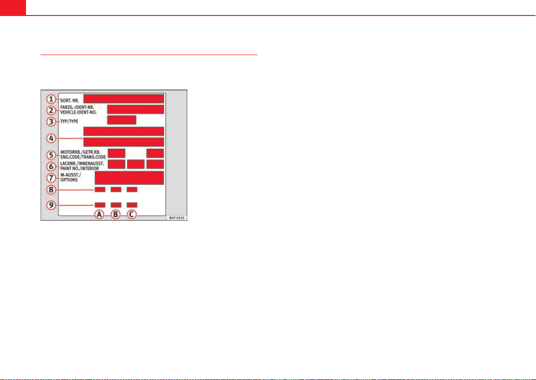
Description of specifications298
Vehicle identification data
The most important information is given on the identification
plate and the vehicle data sticker.
Vehicles for certain export countries do not have an identification plate.
Identification plate
The identification plate is located on the left rib inside the engine compart-
ment.
Vehicle identification number
The vehicle identification number (chassis number) can be read from outside
the vehicle through a viewer in the windscreen. This is located on the left-
hand side of the vehicle in the lower area of the windscreen. It is also located
on the right hand side of the engine compartment.
Vehicle data
The data sticker is placed on the inside of the spare wheel recess in the
luggage compartment.
The following information is provided on the vehicle data sticker: ⇒ fig. 247.
These data are also provided in the Maintenance Programme.
Production control number
Vehicle identification number (chassis number)
Model code number
Model designation / engine power output
Engine and gearbox code letters
Paintwork number / interior trim code
Optional equipment codes
Consumption values
CO
2
emissions values
Data from 2 to 9 are also provided in the Maintenance Programme.
Consumption figures and CO
2
Consumption (litres/100 km) / CO
2
emissions (g/km) urban
Consumption (litres/100 km) / CO
2
emissions (g/km) motorway
Consumption (litres/100 km) / CO
2
emissions (g/km) mixed
Fig. 247 Vehicle data
sticker (luggage compart-
ment)
A
1
A
2
A
3
A
4
A
5
A
6
A
7
A
8
A
9
A
A
A
B
A
C
ExeoST_EN.book Seite 298 Freitag, 3. September 2010 11:41 11
Description of specifications 299
Safety First Operating Instructions Practical Tips Technical Specifications
Information on fuel consumption
Fuel consumption
The consumption and emission details shown on the vehicle
data sticker differ from one vehicle to another.
The fuel consumption and CO
2
emissions of the vehicle can be found on the
vehicle data sticker.
The fuel consumption and emissions figures given are based on the vehicle
weight category, which is determined according to the engine/gearbox
combination and the equipment fitted.
The consumption and emission figures are calculated in accordance with the
tests indicated in regulations 715/2007/EC and 692/2008/EC.
Note
• Actual consumption may vary from quoted test values, depending on
personal driving style, road and traffic conditions, the weather and the
vehicle condition.
Weights
Kerb weight refers to the basic model with a fuel tank filled to 90% capacity
and without optional extras. The figure quoted includes 75 kg to allow for the
weight of the driver.
For special versions and optional equipment fittings or for the addition of
accessories, the weight of the vehicle will increase ⇒ .
WARNING
• Please note that the centre of gravity may shift when transporting
heavy objects; this may affect the vehicle's handling and lead to an acci-
dent. Always adjust your speed and driving style to suit road conditions
and requirements.
• Never exceed the gross axle weight rating or the gross vehicle weight
rating. If the allowed axle load or the allowed total weight is exceeded, the
driving characteristics of the vehicle may change, leading to accidents,
injuries and damage to the vehicle.
Towing a trailer
Trailer weights
Trailer weight
The trailer weights and drawbar loads approved are selected in intensive
trials according to precisely defined criteria. The approved trailer weights are
valid for vehicles in the EU for maximum speeds of 80 km/h (in certain
circumstances up to 100 km/h). The figures may be different in other coun-
tries. All data in the official vehicle documents take precedence over these
data ⇒ .
Drawbar load
The maximum permitted drawbar load on the ball joint of the towing bracket
must not exceed 75 kg.
In the interest of road safety, we recommend that you always tow
approaching the maximum drawbar load. The response of the trailer on the
road will be poor if the drawbar load is too small.
ExeoST_EN.book Seite 299 Freitag, 3. September 2010 11:41 11
Description of specifications300
If the maximum permissible drawbar load cannot be met (e.g. with small,
empty and light-weight single axle trailers or tandem axle trailers with a
wheelbase of less than 1 metre), at least 4% of the actual trailer weight is a
legal stipulation for a drawbar load.
WARNING
• For safety reasons, do not exceed the 80 km/h limit. This is also valid in
countries where higher speeds are permitted.
• Never exceed the maximum trailer weights or the drawbar load. If the
permissible axle load or the permissible total weight is exceeded, the
driving characteristics of the vehicle may change, leading to accidents,
injuries and damage to the vehicle.
Wheels
Tyre pressure, snow chains, wheel bolts
Tyre pressures
The sticker with the tyre pressure values can be found on the inside of the
tank flap. The tyre pressure values given there are for cold tyres. The slightly
raised pressures of warm tyres must not be reduced. ⇒
Snow chains
Snow chains may be fitted only to the front wheels.
Consult the chapter “wheels” of this manual.
Wheel bolts
After the wheels have been changed, the tightening torque of the wheel bolts
should be checked as soon as possible with a torque wrench ⇒ . The tight-
ening torque for steel and alloy wheels is 120 Nm.
WARNING
• Check the tyre pressure at least once per month. Checking the tyre
pressure is very important. If the tyre pressure is too high or too low, there
is an increased danger of accidents, particularly at high speeds.
• If the torque of the wheel bolts is too low, they could loosen while the
vehicle is in motion. Risk of accident! If the tightening torque is too high,
the wheel bolts and threads can be damaged.
Note
We recommend that you ask your Authorised Service Centre for information
about appropriate wheel, tyre and snow chain size.
ExeoST_EN.book Seite 300 Freitag, 3. September 2010 11:41 11
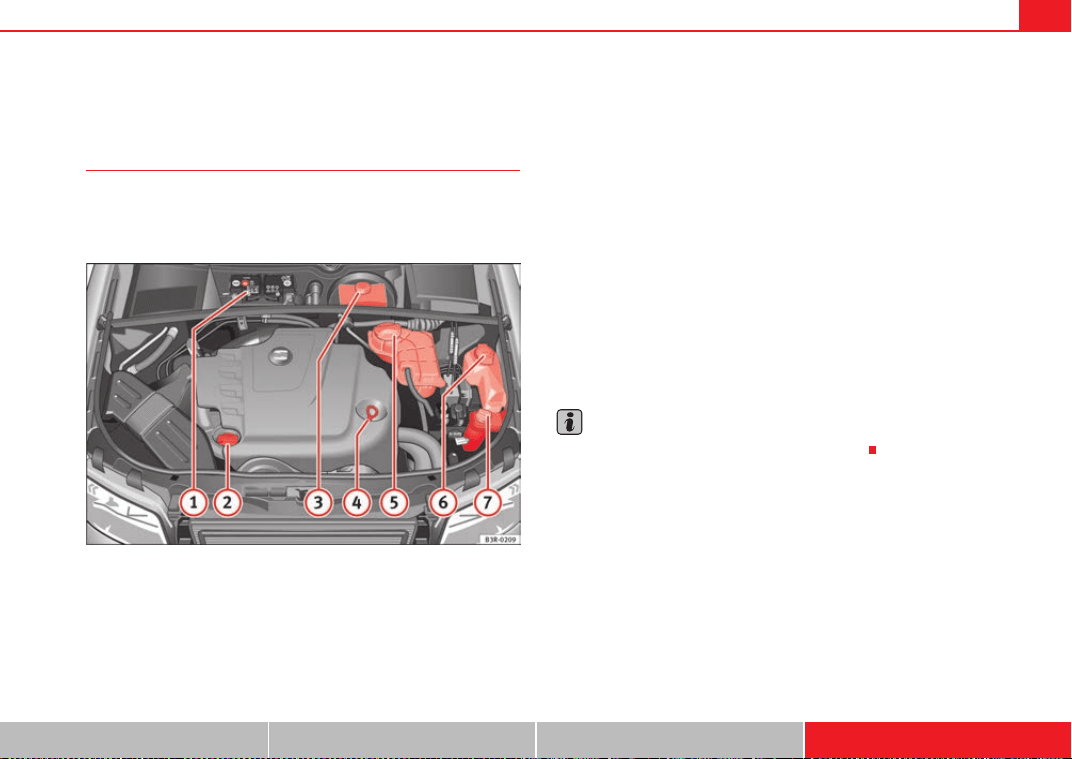
Technical Specifications 301
Safety First Operating Instructions Practical Tips Technical Specifications
Technical Specifications
Checking fluid levels
From time to time, the levels of the different fluids in the
vehicle must be checked. Never fill with incorrect fluids,
otherwise serious damage to the engine may be caused.
Fig. 248 Diagram for the location of the various elements
Vehicle battery
Engine oil filler cap
Brake fluid reservoir
Engine oil dipstick
Coolant expansion tank
Windscreen washer fluid container
Hydraulic fluid reservoir for power steering
The checking and refilling of service fluids are carried out on the components
mentioned above. These operations are described in the ⇒ page 229.
Overview
You will find further explanations, instructions and restrictions on the tech-
nical specifications as of ⇒ page 297.
Note
The layout of parts may vary depending on the engine.
A
1
A
2
A
3
A
4
A
5
A
6
A
7
ExeoST_EN.book Seite 301 Freitag, 3. September 2010 11:41 11
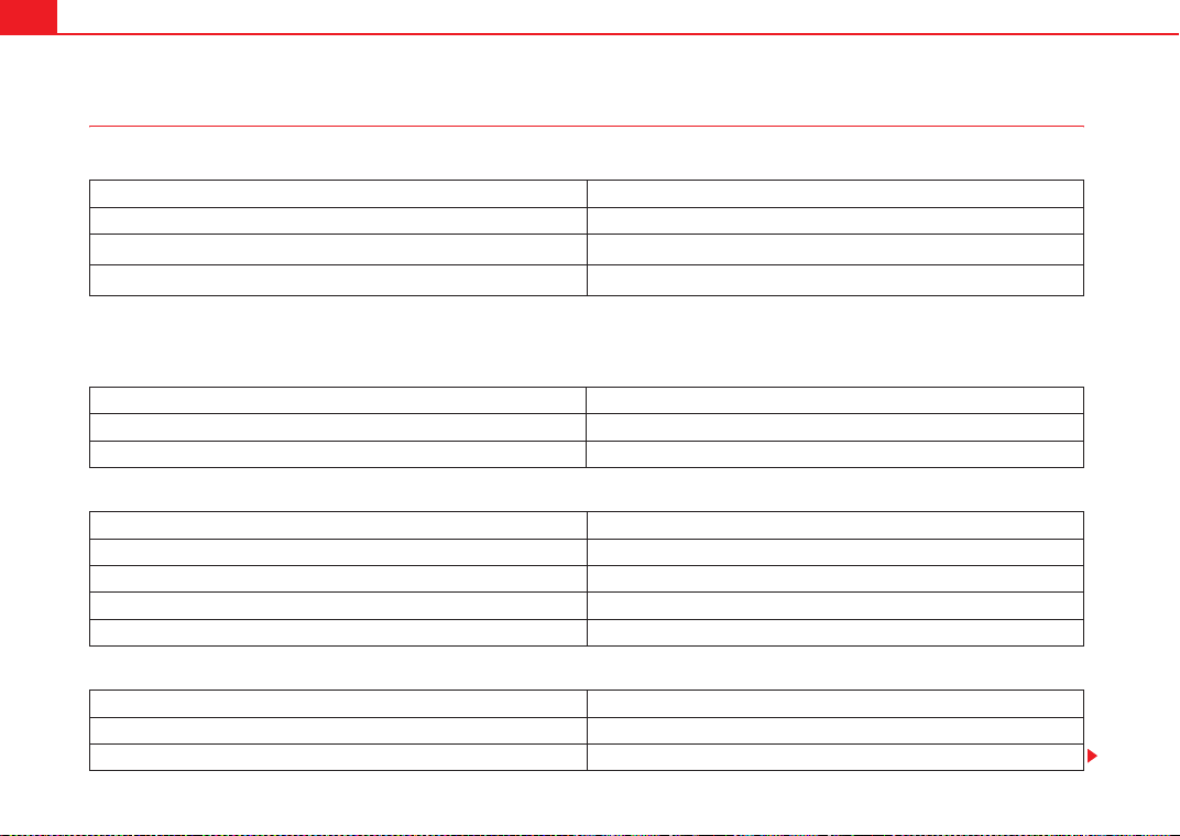
Technical Specifications302
Petrol engine 1.8 88 kW (120 PS)
Engine specifications
Performance
Weights
Trailer weight
Power output in kW (PS) rpm 88 (120) / 3650-6200
Maximum torque in Nm at rpm 230 / 1500-3650
No. of cylinders/ capacity
in cm
3
4 / 1798
Fuel
Super 95 RON
a)
/Normal 91 RON
b)
a)
Research- Octane- Number = Anti-detonation rating of the petrol.
b)
Slight power loss.
Maximum speed in km/h 196
Acceleration from 0-80 km/h in sec. 7.3
Acceleration from 0-100 km/h in sec. 11.1
Gross vehicle weight in kg 2040
Weight in running order (with driver) in kg 1555
Gross front axle weight in kg 1075
Gross rear axle weight in kg 1090
Permitted roof load in kg 75
Trailer without brakes 750
Trailer with brakes, gradients up to 8% 1500
Trailer with brakes, gradients up to 12% 1300
ExeoST_EN.book Seite 302 Freitag, 3. September 2010 11:41 11

Technical Specifications 303
Safety First Operating Instructions Practical Tips Technical Specifications
Engine oil capacity
Petrol engine 1.8 118 kW (160 PS)
Engine specifications
Performance
Weights
Approximate engine oil capacity with oil filter change 4.6 litres
Power output in kW (PS) rpm 118 (160) / 4500-6200
Maximum torque in Nm at rpm 250 / 1500-4500
No. of cylinders/ capacity
in cm
3
4 / 1798
Fuel
Super 95 RON
a)
/Super 91 RON
b)
a)
Research- Octane- Number = Anti-detonation rating of the petrol.
b)
Slight power loss.
Maximum speed in km/h 218
Acceleration from 0-80 km/h in sec. 6.1
Acceleration from 0-100 km/h in sec. 8.9
Gross vehicle weight in kg 2040
Weight in running order (with driver) in kg 1555
Gross front axle weight in kg 1075
Gross rear axle weight in kg 1090
Permitted roof load in kg 75
ExeoST_EN.book Seite 303 Freitag, 3. September 2010 11:41 11
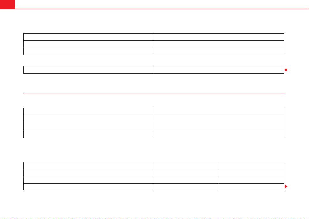
Technical Specifications304
Trailer weight
Engine oil capacity
Petrol engine 2.0 147 kW (200 PS)
Engine specifications
Performance
Trailer without brakes 750
Trailer with brakes, gradients up to 8% 1600
Trailer with brakes, gradients up to 12% 1400
Approximate engine oil capacity with oil filter change 4.6 litres
Power output in kW (PS) rpm 147 (200) / 5100-6000
Maximum torque in Nm at rpm 280 / 1800-5000
No. of cylinders/ capacity
in cm
3
4 / 1984
Fuel
Super 98 RON
a)
/Super 95 RON
b)
a)
Research- Octane- Number = Anti-detonation rating of the petrol.
b)
Slight power loss.
Manual Automatic
Maximum speed in km/h 235 230
Acceleration from 0-80 km/h in sec. 5.6 5.4
Acceleration from 0-100 km/h in sec. 7.6 7.6
ExeoST_EN.book Seite 304 Freitag, 3. September 2010 11:41 11
Technical Specifications 305
Safety First Operating Instructions Practical Tips Technical Specifications
Weights
Trailer weight
Engine oil capacity
Petrol engine 2.0 155 kW (210 PS)
Engine specifications
Manual Automatic
Gross vehicle weight in kg 2050 2075
Weight in running order (with driver) in kg 1565 1590
Gross front axle weight in kg 1090 1115
Gross rear axle weight in kg 1090 1090
Permitted roof load in kg 75 75
Manual Automatic
Trailer without brakes 750 750
Trailer with brakes, gradients up to 8% 1600 1700
Trailer with brakes, gradients up to 12% 1400 1500
Approximate engine oil capacity with oil filter change 4.5 litres
Power output in kW (PS) rpm 155 (210) / 4600-6000
Maximum torque in Nm at rpm 320 / 1500-4600
No. of cylinders/ capacity
in cm
3
4 / 1984
Fuel
Super 95 RON
a)
/Super 91 RON
b)
a)
Research- Octane- Number = Anti-detonation rating of the petrol.
b)
Slight power loss.
ExeoST_EN.book Seite 305 Freitag, 3. September 2010 11:41 11
Technical Specifications306
Performance
Weights
Trailer weight
Engine oil capacity
Maximum speed in km/h 239
Acceleration from 0-80 km/h in sec. 5.4
Acceleration from 0-100 km/h in sec. 7.3
Gross vehicle weight in kg 2050
Weight in running order (with driver) in kg 1565
Gross front axle weight in kg 1090
Gross rear axle weight in kg 1135
Permitted roof load in kg 75
Trailer without brakes 750
Trailer with brakes, gradients up to 8% 1700
Trailer with brakes, gradients up to 12% 1500
Approximate engine oil capacity with oil filter change 4.6 litres
ExeoST_EN.book Seite 306 Freitag, 3. September 2010 11:41 11
Technical Specifications 307
Safety First Operating Instructions Practical Tips Technical Specifications
Diesel engine 2.0 TDI CR 88 kW (120 PS)
Engine specifications
Performance
Weights
Trailer weight
Power output in kW (PS) rpm 88 (120) / 4000
Maximum torque in Nm at rpm 290 / 1750-2500
No. of cylinders/ capacity
in cm
3
4 / 1968
Fuel
Min. 51 CN
a)
a)
Cetane- Number (cetane index) = Measure of the combustion power of the diesel
Maximum speed in km/h 196
Acceleration from 0-80 km/h in sec. 7.5
Acceleration from 0-100 km/h in sec. 10.9
Gross vehicle weight in kg 2050
Weight in running order (with driver) in kg 1565
Gross front axle weight in kg 1100
Gross rear axle weight in kg 1105
Permitted roof load in kg 75
Trailer without brakes 750
Trailer with brakes, gradients up to 8% 1500
Trailer with brakes, gradients up to 12% 1300
ExeoST_EN.book Seite 307 Freitag, 3. September 2010 11:41 11
Technical Specifications308
Engine oil capacity
Diesel engine 2.0 TDI CR 105 kW (143 PS)
Engine specifications
Performance
Weights
Approximate engine oil capacity with oil filter change 4.3 litres
Power output in kW (PS) rpm 105 (143) / 4200
Maximum torque in Nm at rpm 320 / 1750-2500
No. of cylinders/ capacity
in cm
3
4 / 1968
Fuel
Min. 51 CN
a)
a)
Cetane- Number (cetane index) = Measure of the combustion power of the diesel
Maximum speed in km/h 209
Acceleration from 0-80 km/h in sec. 6.5
Acceleration from 0-100 km/h in sec. 9.6
Gross vehicle weight in kg 2050
Weight in running order (with driver) in kg 1565
Gross front axle weight in kg 1100
Gross rear axle weight in kg 1105
Permitted roof load in kg 75
ExeoST_EN.book Seite 308 Freitag, 3. September 2010 11:41 11
Technical Specifications 309
Safety First Operating Instructions Practical Tips Technical Specifications
Trailer weight
Engine oil capacity
Diesel engine 2.0 TDI CR 125 kW (170 PS)
Engine specifications
Performance
Trailer without brakes 750
Trailer with brakes, gradients up to 8% 1800
Trailer with brakes, gradients up to 12% 1600
Approximate engine oil capacity with oil filter change 4.3 litres
Power output in kW (PS) rpm 125 (170) / 4200
Maximum torque in Nm at rpm 350 / 1750-2500
No. of cylinders/ capacity
in cm
3
4 / 1968
Fuel
Min. 51 CN
a)
a)
Cetane- Number (cetane index) = Measure of the combustion power of the diesel
Maximum speed in km/h 224
Acceleration from 0-80 km/h in sec. 6.1
Acceleration from 0-100 km/h in sec. 8.6
ExeoST_EN.book Seite 309 Freitag, 3. September 2010 11:41 11
Technical Specifications310
Weights
Trailer weight
Engine oil capacity
Gross vehicle weight in kg 2075
Weight in running order (with driver) in kg 1590
Gross front axle weight in kg 1115
Gross rear axle weight in kg 1135
Permitted roof load in kg 75
Trailer without brakes 750
Trailer with brakes, gradients up to 8% 1800
Trailer with brakes, gradients up to 12% 1600
Approximate engine oil capacity with oil filter change 4.3 litres
ExeoST_EN.book Seite 310 Freitag, 3. September 2010 11:41 11
Technical Specifications 311
Safety First Operating Instructions Practical Tips Technical Specifications
Dimensions and capacities
Dimensions
Length, width
4661-4741
a)
mm/ 1772 mm
a)
With towing eye.
Height at kerb weight 1454 mm with roof bars
Front and rear projection
976 mm/ 1048-1123
a)
mm
Wheelbase 2642 mm
Turning circle 11.2 m
Track width
b)
b)
This data will change depending on the type of wheel rim.
Front Rear
1522 mm 1523 mm
Capacities
Fuel tank 70 l. Reserve 10 l.
Windscreen washer fluid container with headlight washer 4.8 l.
Tyre pressure
Summer-grade tyres:
The correct tyre pressure can be seen on the sticker on the inside of the tank flap.
Winter tyres:
The pressure of these tyres is the same as the summer tyre pressure plus 0.2 bar.
ExeoST_EN.book Seite 311 Freitag, 3. September 2010 11:41 11

ExeoST_EN.book Seite 312 Freitag, 3. September 2010 11:41 11

Index 313
Index
230 V socket . . . . . . . . . . . . . . . . . . . . . . . . . . . 157
A
Accessories . . . . . . . . . . . . . . . . . . . . . . . . . . . . 223
Towing . . . . . . . . . . . . . . . . . . . . . . . . . . . . . 205
Adaptive headlights . . . . . . . . . . . . . . . . . . . . . 122
Faulty . . . . . . . . . . . . . . . . . . . . . . . . . . . . . . . 81
Air conditioner
2C-Climatronic . . . . . . . . . . . . . . . . . . . . . . . 162
Air distribution . . . . . . . . . . . . . . . . . . . . . . . 169
Air outlets . . . . . . . . . . . . . . . . . . . . . . . . . . . 169
Air purity sensor . . . . . . . . . . . . . . . . . . . . . . 167
Air recirculation . . . . . . . . . . . . . . . . . . . . . . 166
Air recirculation (automatic) . . . . . . . . . . . . 167
Automatic mode . . . . . . . . . . . . . . . . . . . . . 165
Blower . . . . . . . . . . . . . . . . . . . . . . . . . . . . . . 168
Controls . . . . . . . . . . . . . . . . . . . . . . . . . . . . 164
Defrosting . . . . . . . . . . . . . . . . . . . . . . . . . . . 166
ECON Mode (economy) . . . . . . . . . . . . . . . . 166
Economical use . . . . . . . . . . . . . . . . . . . . . . 170
Key settings . . . . . . . . . . . . . . . . . . . . . . . . . 170
Solar-powered blower/sunroof . . . . . . . . . . 171
Temperature selection . . . . . . . . . . . . . . . . . 165
Air duct
Fitting . . . . . . . . . . . . . . . . . . . . . . . . . 269, 276
Removing . . . . . . . . . . . . . . . . . . . . . . 268, 275
Air purity sensor . . . . . . . . . . . . . . . . . . . . . . . . . 167
Airbag
Warning lamp . . . . . . . . . . . . . . . . . . . . . . . . . 66
Airbag covers . . . . . . . . . . . . . . . . . . . . . . . . . . . . 34
Airbag system . . . . . . . . . . . . . . . . . . . . . . . . . . . 28
Curtain airbags . . . . . . . . . . . . . . . . . . . . . . . 41
Front airbags . . . . . . . . . . . . . . . . . . . . . . . . . 32
Side airbags . . . . . . . . . . . . . . . . . . . . . . . . . . 38
Warning lamp . . . . . . . . . . . . . . . . . . . . . . . . . 29
Alternator
Warning lamp . . . . . . . . . . . . . . . . . . . . . . . . . 69
Ambient lighting . . . . . . . . . . . . . . . . . . . . . . . . 125
Antifreeze . . . . . . . . . . . . . . . . . . . . . . . . . . . . . . 233
Anti-lock brake system
How it works . . . . . . . . . . . . . . . . . . . . . . . . . 192
Anti-theft alarm system . . . . . . . . . . . . . . . . . . . 107
Interior monitoring . . . . . . . . . . . . . . . . . . . 108
Aquaplaning . . . . . . . . . . . . . . . . . . . . . . . . . . . 249
Armrest
Storage compartment in front armrest . . . . 142
Armrests
Adjusting the front armrest . . . . . . . . . . . . . 142
Ashtray
Front . . . . . . . . . . . . . . . . . . . . . . . . . . . . . . . 154
Rear . . . . . . . . . . . . . . . . . . . . . . . . . . . . . . . 154
Athermic windscreen . . . . . . . . . . . . . . . . . . . . . 224
Auto-check system . . . . . . . . . . . . . . . . . . . . . . . 75
Automatic car wash tunnel . . . . . . . . . . . . . . . . 215
Automatic gearbox
Dynamic gear control programme . . . . . . . 188
Kick-down feature . . . . . . . . . . . . . . . . . . . . 187
multitronic® . . . . . . . . . . . . . . . . . . . . . . . . 183
Paddle levers (tiptronic mode) . . . . . . . . . . 190
Safety interlock for ignition key . . . . . . . . . 173
Selector lever lock . . . . . . . . . . . . . . . . . . . . 187
Selector lever positions . . . . . . . . . . . . . . . 185
Steering wheel with paddle levers . . . . . . . 190
tiptronic . . . . . . . . . . . . . . . . . . . . . . . 183, 189
Automatic headlight control . . . . . . . . . . . . . . . 116
Auxiliary heater . . . . . . . . . . . . . . . . . . . . . . . . . 171
B
Battery . . . . . . . . . . . . . . . . . . . . . . . . . . . . . . . . 241
Battery voltage . . . . . . . . . . . . . . . . . . . . . . . . 81
Charging . . . . . . . . . . . . . . . . . . . . . . . . . . . . 243
Disconnection . . . . . . . . . . . . . . . . . . . . . . . 241
Long periods of non-use . . . . . . . . . . . . . . . 241
Replacing . . . . . . . . . . . . . . . . . . . . . . 241, 242
Testing . . . . . . . . . . . . . . . . . . . . . . . . . . . . . 241
Winter operation . . . . . . . . . . . . . . . . 241, 242
Bicycle rack
Towing . . . . . . . . . . . . . . . . . . . . . . . . . . . . . 205
Biodiesel . . . . . . . . . . . . . . . . . . . . . . . . . . . . . . 227
Biodiesel fuel . . . . . . . . . . . . . . . . . . . . . . . . . . . 227
ExeoST_EN.book Seite 313 Freitag, 3. September 2010 11:41 11

Index314
Bonnet . . . . . . . . . . . . . . . . . . . . . . . . . . . . . . . . 228
Closing . . . . . . . . . . . . . . . . . . . . . . . . . . . . . 230
Opening . . . . . . . . . . . . . . . . . . . . . . . . . . . . 229
Releasing . . . . . . . . . . . . . . . . . . . . . . . . . . . 228
Brake light
Failure control . . . . . . . . . . . . . . . . . . . . . . . . 80
Brake pads . . . . . . . . . . . . . . . . . . . . . . . . . . . . . 197
Brake servo . . . . . . . . . . . . . . . . . . . . . . . . . . . . 197
Brake system
Brake servo . . . . . . . . . . . . . . . . . . . . . . . . . 194
Brakes . . . . . . . . . . . . . . . . . . . . . . . . . . . . . 194
Malfunction . . . . . . . . . . . . . . . . . . . . . . . . . . 77
Brakes . . . . . . . . . . . . . . . . . . . . . . . . . . . . . . . . 197
Brake assist system . . . . . . . . . . . . . . . . . . 193
Brake fluid . . . . . . . . . . . . . . . . . . . . . . . . . . 240
Worn brake pads . . . . . . . . . . . . . . . . . . . . . . 81
Braking distance . . . . . . . . . . . . . . . . . . . . . . . . 197
Bulb change
General notes . . . . . . . . . . . . . . . . . . . . . . . 267
C
Catalytic converter . . . . . . . . . . . . . . . . . . . . . . 198
CD-ROM player . . . . . . . . . . . . . . . . . . . . . . . . . 149
Central locking . . . . . . . . . . . . . . . . . . . . . . . . . . 98
Manual locking . . . . . . . . . . . . . . . . . . . . . . 102
Sunroof: opening and closing . . . . . . . . . . 113
Central locking system
Anti-theft security system . . . . . . . . . . . . . . 100
Locking . . . . . . . . . . . . . . . . . . . . . . . . . . . . . 99
Locking and unlocking the vehicle from inside
100
Opening and closing the windows . . . . . . 111
Security central locking . . . . . . . . . . . . . . . 101
Switch on the driver door . . . . . . . . . . . . . . 100
Tailgate . . . . . . . . . . . . . . . . . . . . . . . . . . . . 103
Unlocking . . . . . . . . . . . . . . . . . . . . . . . . . . . 99
Cetane number . . . . . . . . . . . . . . . . . . . . . . . . . 227
Changing the main headlight bulb
Main headlight . . . . . . . . . . . . . . . . . . . . . . 271
Changing the main headlight bulbs
Dipped beam headlight . . . . . . . . . . . . . . . 272
Changing the tail lights
Luggage compartment lights . . . . . . . . . . . 289
Changing windscreen wiper blades . . . . . . . . . 238
Chassis number . . . . . . . . . . . . . . . . . . . . . . . . 298
Child safety . . . . . . . . . . . . . . . . . . . . . . . . . . . . . 46
Child safety seat
ISOFIX system . . . . . . . . . . . . . . . . . . . . . . . . 52
Child seat . . . . . . . . . . . . . . . . . . . . . . . . . . . . . . . 48
Categorisation in groups . . . . . . . . . . . . . . . 48
Group 1 . . . . . . . . . . . . . . . . . . . . . . . . . . . . . 49
Group 2 . . . . . . . . . . . . . . . . . . . . . . . . . . . . . 49
Group 3 . . . . . . . . . . . . . . . . . . . . . . . . . . . . . 49
Groups 0 and 0+ . . . . . . . . . . . . . . . . . . . . . . 48
Securing . . . . . . . . . . . . . . . . . . . . . . . . . . . . . 51
Child seats
on the front passenger seat . . . . . . . . . . . . . 29
Safety notes . . . . . . . . . . . . . . . . . . . . . . . . . . 46
Childproof lock
Rear doors . . . . . . . . . . . . . . . . . . . . . . . . . . 104
Cigarette lighter . . . . . . . . . . . . . . . . . . . . . . . . 155
Cleaning alloy wheel rims . . . . . . . . . . . . . . . . 219
Cleaning chrome . . . . . . . . . . . . . . . . . . . . . . . . 218
Cleaning engine compartment . . . . . . . . . . . . . 220
Cleaning steel wheel rims . . . . . . . . . . . . . . . . 219
Cleaning windows . . . . . . . . . . . . . . . . . . . . . . . 217
Clock, setting . . . . . . . . . . . . . . . . . . . . . . . . . . . 61
Cloth seat covers cleaning . . . . . . . . . . . . . . . . 221
Coat hooks . . . . . . . . . . . . . . . . . . . . . . . . . . . . 160
Cockpit . . . . . . . . . . . . . . . . . . . . . . . . . . . . . . . . . 57
Overview . . . . . . . . . . . . . . . . . . . . . . . . . . . . 57
Compartments . . . . . . . . . . . . . . . . . . . . . . . . . . 159
In the door trim . . . . . . . . . . . . . . . . . . . . . . 160
In the front seats . . . . . . . . . . . . . . . . . . . . . 161
Coolant
Checking the level . . . . . . . . . . . . . . . . . . . 234
Coolant fluid
Antifreeze . . . . . . . . . . . . . . . . . . . . . . . . . . 233
Coolant fluid additive . . . . . . . . . . . . . . . . . 233
Topping up . . . . . . . . . . . . . . . . . . . . . . . . . 235
Cooling system
Coolant temperature gauge . . . . . . . . . . . . . 60
Malfunction . . . . . . . . . . . . . . . . . . . . . . . . . . 78
Correct adjustment of front seat head restraints . .
13
Correct adjustment of rear seat head restraints
In-use and non-use positions . . . . . . . . . . . 14
Correct sitting position
Front passenger . . . . . . . . . . . . . . . . . . . . . . 12
Incorrect sitting position . . . . . . . . . . . . . . . 14
Cruise control . . . . . . . . . . . . . . . . . . . . . . . . . . 180
ExeoST_EN.book Seite 314 Freitag, 3. September 2010 11:41 11

Index 315
Cruise control system . . . . . . . . . . . . . . . . . . . . 180
Adjust the stored speed . . . . . . . . . . . . . . . 181
Deactivating . . . . . . . . . . . . . . . . . . . . . . . . . 182
Deactivating temporarily . . . . . . . . . . . . . . . 182
Setting the speed . . . . . . . . . . . . . . . . . . . . 181
Curtain airbags . . . . . . . . . . . . . . . . . . . . . . . . . . 41
Description . . . . . . . . . . . . . . . . . . . . . . . . . . . 41
Operation . . . . . . . . . . . . . . . . . . . . . . . . . . . . 42
Safety notes . . . . . . . . . . . . . . . . . . . . . . . . . . 42
D
Danger of fitting a child seat on the front passenger
seat . . . . . . . . . . . . . . . . . . . . . . . . . . . . . . . 29
Dash panel cleaning . . . . . . . . . . . . . . . . . . . . . 220
Data entry control . . . . . . . . . . . . . . . . . . . . . . . . 88
Date display . . . . . . . . . . . . . . . . . . . . . . . . . . . . . 61
Daytime running lights . . . . . . . . . . . . . . . . . . . 121
Deactivating front passenger airbag
Safety notes . . . . . . . . . . . . . . . . . . . . . . . . . . 45
Deactivating the airbag
Front passenger airbag . . . . . . . . . . . . . . . . . 44
Diesel . . . . . . . . . . . . . . . . . . . . . . . . . . . . . . . . . 227
Diesel engine
Winter driving . . . . . . . . . . . . . . . . . . . . . . . . 227
Diesel engine particulate filter . . . . . . . . . . . . . 199
Diesel particulate filter . . . . . . . . . . . . . . . . . . . . 80
Engine oil . . . . . . . . . . . . . . . . . . . . . . . . . . . 230
Digital clock . . . . . . . . . . . . . . . . . . . . . . . . . . . . . 61
Dipped beam headlights . . . . . . . . . . . . . . . . . 116
DIS
Average fuel consumption . . . . . . . . . . . . . . 85
Average speed . . . . . . . . . . . . . . . . . . . . . . . . 85
Driving time . . . . . . . . . . . . . . . . . . . . . . . . . . 85
Instantaneous fuel consumption . . . . . . . . . 85
Disposal
Airbags . . . . . . . . . . . . . . . . . . . . . . . . . . . . . . 30
Seat belt tensioners . . . . . . . . . . . . . . . . . . . 27
Distance covered . . . . . . . . . . . . . . . . . . . . . . . . . 86
Distance to empty . . . . . . . . . . . . . . . . . . . . . 73, 85
Door and tailgate warning . . . . . . . . . . . . . . . . . 74
Door lock cylinders . . . . . . . . . . . . . . . . . . . . . . 218
Doors
Childproof lock . . . . . . . . . . . . . . . . . . . . . . 104
Locking the doors manually if the central lock-
ing fails to work . . . . . . . . . . . . . . . . . . . . 102
Driver
See Correct sitting position . . . . . . . . . . . . . . 10
Driver information system . . . . . . . . . . . . . . . . . . 71
Auto-check system . . . . . . . . . . . . . . . . . . . . 75
CD and radio display . . . . . . . . . . . . . . . . . . . 72
Door and tailgate warning . . . . . . . . . . . . . . 74
Driver messages . . . . . . . . . . . . . . . . . . . . . . 76
Handbrake warning . . . . . . . . . . . . . . . . . . . . 76
Menu display . . . . . . . . . . . . . . . . . . . . . . . . . 87
Onboard computer . . . . . . . . . . . . . . . . . . . . 85
Outside temperature display . . . . . . . . . . . . 72
Red symbols . . . . . . . . . . . . . . . . . . . . . . . . . . 77
Speed warning . . . . . . . . . . . . . . . . . . . . . . . . 82
Warning messages . . . . . . . . . . . . . . . . . . . . 76
Yellow symbols . . . . . . . . . . . . . . . . . . . . . . . 79
Driver messages . . . . . . . . . . . . . . . . . . . . . . . . . 76
Driver seat
Activating stored settings . . . . . . . . . . . . . . 139
With memory . . . . . . . . . . . . . . . . . . . . . . . . 138
driver seat
Assigning the key to the seat . . . . . . . . . . . 140
Driving
Driving abroad . . . . . . . . . . . . . . . . . . . . . . . 201
Economically / Environmentally friendly . . 199
Driving abroad . . . . . . . . . . . . . . . . . . . . . . . . . . 201
Headlights . . . . . . . . . . . . . . . . . . . . . . . . . . 202
Driving safety . . . . . . . . . . . . . . . . . . . . . . . . . . . . . 9
DRP
See Dynamic gear control programme . . . . 188
Dynamic gear control programme . . . . . . . . . . 188
E
Economical driving . . . . . . . . . . . . . . . . . . . . . . 199
Electric socket . . . . . . . . . . . . . . . . . . . . . . . . . . 156
Electric windows . . . . . . . . . . . . . . . . . . . . . . . . 109
Central locking system . . . . . . . . . . . . . . . . 111
Possible malfunctions . . . . . . . . . . . . . . . . . 111
Rear doors . . . . . . . . . . . . . . . . . . . . . . . . . . 110
Switch on front passenger's door . . . . . . . 110
Switches in the driver door . . . . . . . . . . . . . 110
Electronic differential lock
How it works . . . . . . . . . . . . . . . . . . . . . . . . 193
Electronic immobiliser . . . . . . . . . . . . . . . . . . . . 98
ExeoST_EN.book Seite 315 Freitag, 3. September 2010 11:41 11

Index316
Electronic Stability Programme
Description . . . . . . . . . . . . . . . . . . . . . . . . . 172
How the system works . . . . . . . . . . . . . . . . 191
Warning lamp . . . . . . . . . . . . . . . . . . . . . . . 173
Emergencies
Changing a wheel . . . . . . . . . . . . . . . . . . . . 257
Disconnecting the battery . . . . . . . . . . . . . 241
Jack . . . . . . . . . . . . . . . . . . . . . . . . . . . . 254, 259
Sunroof emergency activation . . . . . . . . . . 114
Tools . . . . . . . . . . . . . . . . . . . . . . . . . . . . . . . 254
Tyre mobility system . . . . . . . . . . . . . . . . . . 255
Engine
Running in . . . . . . . . . . . . . . . . . . . . . . . . . . 197
Starting . . . . . . . . . . . . . . . . . . . . . . . . . . . . 174
Stop . . . . . . . . . . . . . . . . . . . . . . . . . . . . . . . 175
Engine compartment
Safety instructions . . . . . . . . . . . . . . . . . . . 229
Engine oil . . . . . . . . . . . . . . . . . . . . . . . . . . . . . . 230
Checking oil level . . . . . . . . . . . . . . . . . . . . 232
Consumption . . . . . . . . . . . . . . . . . . . . . . . . 232
Oil pressure too low . . . . . . . . . . . . . . . . . . . 78
Oil properties . . . . . . . . . . . . . . . . . . . . . . . . 231
Oil sensor defective . . . . . . . . . . . . . . . . . . . 80
Topping up . . . . . . . . . . . . . . . . . . . . . . . . . . 233
Engine speed governing . . . . . . . . . . . . . . . . . . . 80
Environment . . . . . . . . . . . . . . . . . . . . . . . . . . . 199
Environmental friendliness . . . . . . . . . . . . 201
Roof racks . . . . . . . . . . . . . . . . . . . . . . . . . . 152
Environmental tip
Avoiding pollution . . . . . . . . . . . . . . . . . . . . 226
Environmentally friendly driving . . . . . . . . . . . 199
ESP
See Electronic Stability Programme . . . . . . 172
Exhaust gas purification system . . . . . . . . . . . 198
Exterior mirrors . . . . . . . . . . . . . . . . . . . . . . . . . 217
F
Fabric trim cleaning . . . . . . . . . . . . . . . . . . . . . 221
Fastening rings . . . . . . . . . . . . . . . . . . . . . . . . . . 17
Floor mats . . . . . . . . . . . . . . . . . . . . . . . . . . . . . . 16
Fog lights . . . . . . . . . . . . . . . . . . . . . . . . . . . . . . 118
Front airbags . . . . . . . . . . . . . . . . . . . . . . . . . . . . 32
Description . . . . . . . . . . . . . . . . . . . . . . . . . . 32
Operation . . . . . . . . . . . . . . . . . . . . . . . . . . . . 33
Safety notes . . . . . . . . . . . . . . . . . . . . . . . . . . 35
Front drink holder . . . . . . . . . . . . . . . . . . . . . . . 153
Front passenger airbag deactivation . . . . . . . . . 44
Fuel
Diesel . . . . . . . . . . . . . . . . . . . . . . . . . . . . . . 227
Fuel gauge . . . . . . . . . . . . . . . . . . . . . . . . . . . 63
Fuel level low . . . . . . . . . . . . . . . . . . . . . . . . . 80
Instantaneous fuel consumption . . . . . . . . . 85
Petrol . . . . . . . . . . . . . . . . . . . . . . . . . . . . . . 226
Fuel tank
opening the fuel tank flap . . . . . . . . . . . . . 225
Fuel: save . . . . . . . . . . . . . . . . . . . . . . . . . . . . . . 199
Fuse
Assignment . . . . . . . . . . . . . . . . . . . . . . . . . 266
Changing . . . . . . . . . . . . . . . . . . . . . . . . . . . 265
G
Gear display . . . . . . . . . . . . . . . . . . . . . . . . . . . . 73
Gear shift pattern . . . . . . . . . . . . . . . . . . . . . . . 183
General overview of the engine compartment 301
Glove compartment . . . . . . . . . . . . . . . . . . . . . 159
Light . . . . . . . . . . . . . . . . . . . . . . . . . . . . . . . 124
GRA . . . . . . . . . . . . . . . . . . . . . . . . . . . . . . . . . . 180
H
Handbrake . . . . . . . . . . . . . . . . . . . . . . . . . . . . . 176
Hazard warning lights . . . . . . . . . . . . . . . . . . . . 122
Head restraint
Rear seat . . . . . . . . . . . . . . . . . . . . . . . . . . . 142
Head restraints
Front seats . . . . . . . . . . . . . . . . . . . . . . . . . . 140
Rear seats . . . . . . . . . . . . . . . . . . . . . . . . . . 141
Removing and fitting . . . . . . . . . . . . . . . . . 141
Headlight range control . . . . . . . . . . . . . . . . . . 120
Dynamic . . . . . . . . . . . . . . . . . . . . . . . . . . . . 121
Faulty . . . . . . . . . . . . . . . . . . . . . . . . . . . . . . . 81
Headlights
Adaptive headlights . . . . . . . . . . . . . . . . . . 122
Automatic headlight control . . . . . . . . . . . 117
Automatic headlight control photosensors 117
Coming home function . . . . . . . . . . . . . . . . 119
Driving abroad . . . . . . . . . . . . . . . . . . . . . . . 202
Front fog lights . . . . . . . . . . . . . . . . . . . . . . 118
Headlight range control . . . . . . . . . . . . . . . 120
ExeoST_EN.book Seite 316 Freitag, 3. September 2010 11:41 11

Index 317
Headlight washer system . . . . . . . . . . . . . . 131
Leaving home function . . . . . . . . . . . . . . . . 119
Heated
Seats . . . . . . . . . . . . . . . . . . . . . . . . . . . . . . . 171
Heated rear window . . . . . . . . . . . . . . . . . . . . . . 127
Heating element wires . . . . . . . . . . . . . . . . 218
Heated seats . . . . . . . . . . . . . . . . . . . . . . . . . . . 171
High pressure cleaners . . . . . . . . . . . . . . . . . . . 216
Horn . . . . . . . . . . . . . . . . . . . . . . . . . . . . . . . . . . . 57
I
Identification number . . . . . . . . . . . . . . . . . . . . 298
Identification plate . . . . . . . . . . . . . . . . . . . . . . 298
Ignition key
Safety interlock . . . . . . . . . . . . . . . . . . . . . . 173
Ignition lock . . . . . . . . . . . . . . . . . . . . . . . . . . . . 173
Indicator lamps
Cruise control system . . . . . . . . . . . . . . . . . . 67
Glow plug system . . . . . . . . . . . . . . . . . . . . . 70
Main beam headlights . . . . . . . . . . . . . . . . . 69
Indicator lamps - overview . . . . . . . . . . . . . . . . . 65
Instruments
Lighting . . . . . . . . . . . . . . . . . . . . . . . . 62, 120
Interior lights
Ambient lighting . . . . . . . . . . . . . . . . . . . . . 125
Front . . . . . . . . . . . . . . . . . . . . . . . . . . . . . . . 124
Luggage compartment . . . . . . . . . . . . . . . . 126
Rear . . . . . . . . . . . . . . . . . . . . . . . . . . . . . . . . 126
Interior mirror
With manual anti-dazzle setting . . . . . . . . . 131
Interior monitoring . . . . . . . . . . . . . . . . . . . . . . 108
Intermittent wipe . . . . . . . . . . . . . . . . . . . . . . . . 128
ISOFIX . . . . . . . . . . . . . . . . . . . . . . . . . . . . . . . . . . 52
J
Jack . . . . . . . . . . . . . . . . . . . . . . . . . . . . . . 254, 259
Jump leads . . . . . . . . . . . . . . . . . . . . . . . . . . . . . 291
Jump-starting . . . . . . . . . . . . . . . . . . . . . . . . . . . 291
K
Keys . . . . . . . . . . . . . . . . . . . . . . . . . . . . . . . . . . . 96
Air conditioner settings . . . . . . . . . . . . . . . . 170
Battery . . . . . . . . . . . . . . . . . . . . . . . . . . . . . . 97
Remote control key . . . . . . . . . . . . . . . . . . . 105
Settings for the driver seat . . . . . . . . . . . . . 140
Kick-down feature . . . . . . . . . . . . . . . . . . . . . . . 187
L
Leather cleaning . . . . . . . . . . . . . . . . . . . . . . . . 221
Lighting . . . . . . . . . . . . . . . . . . . . . . . . . . . . . . . 116
Instruments . . . . . . . . . . . . . . . . . . . . . . 62, 120
Lights
Adaptive headlights . . . . . . . . . . . . . . . . . . 122
Automatic headlight control . . . . . . . . . . . . 116
Cornering light . . . . . . . . . . . . . . . . . . . . . . . 122
Dipped beam headlights faulty . . . . . . . . . . 82
Dynamic headlight range control . . . . . . . . 121
Headlight flasher . . . . . . . . . . . . . . . . . . . . . 124
Parking light . . . . . . . . . . . . . . . . . . . . . . . . . 124
Reverse lights faulty . . . . . . . . . . . . . . . . . . . 82
Switching on and off . . . . . . . . . . . . . . . . . . 116
Xenon lights . . . . . . . . . . . . . . . . . . . . . . . . . 121
Load compartment in the luggage compartment
See Loading the luggage compartment . . . . 16
Loading the luggage compartment . . . . . . . . . . 16
Locking the doors manually if the central locking
fails to work
Locking the doors manually if the central lock-
ing fails to work . . . . . . . . . . . . . . . . . . . . 102
Locks . . . . . . . . . . . . . . . . . . . . . . . . . . . . . . . . . 218
Long periods of non-use
Battery . . . . . . . . . . . . . . . . . . . . . . . . . . . . . 241
Luggage compartment . . . . . . . . . . . . . . . . . . . 143
Cover . . . . . . . . . . . . . . . . . . . . . . . . . . . . . . 145
Extending . . . . . . . . . . . . . . . . . . . . . . . . . . . 149
Fastening rings . . . . . . . . . . . . . . . . . . . . . . 144
Light . . . . . . . . . . . . . . . . . . . . . . . . . . . . . . . 126
Loading . . . . . . . . . . . . . . . . . . . . . . . . . . . . 143
Luggage compartment liner . . . . . . . . . . . . 148
Luggage net . . . . . . . . . . . . . . . . . . . . . . . . . 144
Net partition . . . . . . . . . . . . . . . . . . . . . . . . . 146
Retaining strap . . . . . . . . . . . . . . . . . . . . . . 145
Side storage compartment . . . . . . . . . . . . . 149
Ski bag . . . . . . . . . . . . . . . . . . . . . . . . . . . . . 150
See also Loading the luggage compartment 16
Luggage compartment cover
Removing . . . . . . . . . . . . . . . . . . . . . . . . . . . 147
M
Main beam headlights . . . . . . . . . . . . . . 116, 123
ExeoST_EN.book Seite 317 Freitag, 3. September 2010 11:41 11

Index318
Maintenance
Airbags . . . . . . . . . . . . . . . . . . . . . . . . . . . . . . 30
Maintenance and cleaning . . . . . . . . . . . . . . . . 214
Manual gearbox . . . . . . . . . . . . . . . . . . . . . . . . 183
Manual operation
Closing the sunroof manually . . . . . . . . . . 114
Mirrors
Activating stored settings . . . . . . . . . . . . . . 139
Automatic exterior mirror adjustment . . . . 138
Heated exterior mirrors . . . . . . . . . . . . . . . . 132
Storing settings . . . . . . . . . . . . . . . . . . . . . . 139
Vanity mirrors . . . . . . . . . . . . . . . . . . . . . . . 127
Mobile phones and two-way radios . . . . . . . . . 224
multitronic® . . . . . . . . . . . . . . . . . . . . . . . . . . . 183
Driving with multitronic® . . . . . . . . . . . . . . 184
N
Net partition
Removing . . . . . . . . . . . . . . . . . . . . . . . . . . . 147
Number of seats . . . . . . . . . . . . . . . . . . . . . . . . . 18
O
Observations . . . . . . . . . . . . . . . . . . . . . . . . . . . 201
Octane number . . . . . . . . . . . . . . . . . . . . . . . . . 226
Odometer . . . . . . . . . . . . . . . . . . . . . . . . . . . . . . . 63
Oil consumption . . . . . . . . . . . . . . . . . . . . . . . . 232
Oil dipstick . . . . . . . . . . . . . . . . . . . . . . . . . . . . 232
Oil level
Check level . . . . . . . . . . . . . . . . . . . . . . . . . . 80
Oil properties . . . . . . . . . . . . . . . . . . . . . . . . . . . 231
Onboard computer . . . . . . . . . . . . . . . . . . . . . . . 85
Outside temperature display . . . . . . . . . . . . . . . 72
Overview
Cockpit . . . . . . . . . . . . . . . . . . . . . . . . . . . . . . 57
P
Paddle levers
tiptronic . . . . . . . . . . . . . . . . . . . . . . . . . . . . 190
Paintwork
Polishing . . . . . . . . . . . . . . . . . . . . . . . . . . . 217
Parking . . . . . . . . . . . . . . . . . . . . . . . . . . . . . . . . 177
multitronic® . . . . . . . . . . . . . . . . . . . . . . . . 184
Parking aid
SEAT Parking System . . . . . . . . . . . . . . . . . 178
SEAT Parking System plus . . . . . . . . . . . . . 178
Parking aid acoustic system . . . . . . . . . . . . . . . 177
Passenger
See Correct sitting position . . . . . . . . . . 11, 12
Pedals . . . . . . . . . . . . . . . . . . . . . . . . . . . . . . . . . 15
Petrol . . . . . . . . . . . . . . . . . . . . . . . . . . . . . . . . . 226
Driving abroad . . . . . . . . . . . . . . . . . . . . . . . 201
Petrol additives . . . . . . . . . . . . . . . . . . . . . . . . . 227
Photosensor faulty . . . . . . . . . . . . . . . . . . . . . . . 81
Physical principles of a frontal collision . . . . . . 19
Plastic parts . . . . . . . . . . . . . . . . . . . . . . . . . . . . 217
Plastic parts cleaning . . . . . . . . . . . . . . . . . . . . 220
Power socket . . . . . . . . . . . . . . . . . . . . . . . . . . . 155
Power steering . . . . . . . . . . . . . . . . . . . . . . . . . . 196
Products for vehicle maintenance . . . . . . . . . . 214
Q
Quartz clock . . . . . . . . . . . . . . . . . . . . . . . . . . . . . 61
R
Radiator fan . . . . . . . . . . . . . . . . . . . . . . . . . . . . 236
Radio display . . . . . . . . . . . . . . . . . . . . . . . . . . . . 72
Rain sensor . . . . . . . . . . . . . . . . . . . . . . . . . . . . 128
Rain sensor faulty . . . . . . . . . . . . . . . . . . . . . . . . 81
Reading lights
Front . . . . . . . . . . . . . . . . . . . . . . . . . . . . . . . 124
Rear . . . . . . . . . . . . . . . . . . . . . . . . . . . . . . . 126
Rear drink holder . . . . . . . . . . . . . . . . . . . . . . . . 153
Rear fog light . . . . . . . . . . . . . . . . . . . . . . . . . . . 118
Rear seat bench . . . . . . . . . . . . . . . . . . . . . . . . 149
Rear side window sun blind . . . . . . . . . . . . . . . 128
Rear view mirrors
Anti-dazzle interior mirror with automatic
adjustment . . . . . . . . . . . . . . . . . . . . . . . . 131
Anti-dazzle setting . . . . . . . . . . . . . . . . . . . 131
Interior mirror . . . . . . . . . . . . . . . . . . . . . . . 131
Rear window sun blind . . . . . . . . . . . . . . . . . . . 128
Rear window wash/wipe
Automatic rear window wash/wipe . . . . . . 130
Rear window wiper
Automatic rear window wash/wipe . . . . . . 130
Intermittent wipe . . . . . . . . . . . . . . . . . . . . . 130
Refuelling . . . . . . . . . . . . . . . . . . . . . . . . . . . . . 225
ExeoST_EN.book Seite 318 Freitag, 3. September 2010 11:41 11

Index 319
Registration light . . . . . . . . . . . . . . . . . . . . . . . . 290
Remote control key
Indicator light . . . . . . . . . . . . . . . . . . . . . . . . . 97
Locking and unlocking . . . . . . . . . . . . . . . . 106
Locking and unlocking the vehicle . . . . . . . 106
Replacing the battery . . . . . . . . . . . . . . . . . . 97
Remote control keys . . . . . . . . . . . . . . . . . . . . . . 96
Re-synchronising . . . . . . . . . . . . . . . . . . . . . 107
Removing and fitting the wheel . . . . . . . . . . . . 260
Repairs
Airbags . . . . . . . . . . . . . . . . . . . . . . . . . . . . . . 30
Replacement of parts . . . . . . . . . . . . . . . . . . . . 223
Rev counter . . . . . . . . . . . . . . . . . . . . . . . . . . . . . 61
Reverse gear
Automatic gearbox . . . . . . . . . . . . . . . . . . . 185
Manual gearbox . . . . . . . . . . . . . . . . . . . . . . 183
Roof rack . . . . . . . . . . . . . . . . . . . . . . . . . . . . . . 151
Attachment points . . . . . . . . . . . . . . . . . . . . 152
Roof load . . . . . . . . . . . . . . . . . . . . . . . . . . . 152
Roof rails . . . . . . . . . . . . . . . . . . . . . . . . . . . . . . 151
Rubber seals . . . . . . . . . . . . . . . . . . . . . . . . . . . 218
Run-flat tyres . . . . . . . . . . . . . . . . . . . . . . . . . . . 250
Running in
Engine . . . . . . . . . . . . . . . . . . . . . . . . . . . . . 197
S
SAFE . . . . . . . . . . . . . . . . . . . . . . . . . . . . . . . . . . . 98
Safe driving . . . . . . . . . . . . . . . . . . . . . . . . . . . . . . 7
Aspects to take into account . . . . . . . . . . . . . 8
Before setting off . . . . . . . . . . . . . . . . . . . . . . . 8
Driving safety . . . . . . . . . . . . . . . . . . . . . . . . . . 8
Safety . . . . . . . . . . . . . . . . . . . . . . . . . . . . . . . . . . . 9
Safety equipment . . . . . . . . . . . . . . . . . . . . . . . . . 7
Safety instructions
Engine compartment . . . . . . . . . . . . . . . . . . 229
Safety notes
Airbags . . . . . . . . . . . . . . . . . . . . . . . . . . . . . . 30
Curtain airbags . . . . . . . . . . . . . . . . . . . . . . . 42
Deactivating front passenger airbag . . . . . . 45
Front airbags . . . . . . . . . . . . . . . . . . . . . . . . . 35
Seat belt tensioners . . . . . . . . . . . . . . . . . . . 27
Side airbags . . . . . . . . . . . . . . . . . . . . . . . . . . 40
Using child seats . . . . . . . . . . . . . . . . . . . . . . 46
Using seat belts . . . . . . . . . . . . . . . . . . . . . . . 21
Seals . . . . . . . . . . . . . . . . . . . . . . . . . . . . . . . . . . 218
Seat adjustment
Lumbar support . . . . . . . . . . . . . . . . . . . . . . 137
Seat belt cleaning . . . . . . . . . . . . . . . . . . . . . . . 221
Seat belt position
Pregnant women . . . . . . . . . . . . . . . . . . . . . . 24
Seat belts . . . . . . . . . . . . . . . . . . . . . . . . . . . . 23
Seat belt protection . . . . . . . . . . . . . . . . . . . . . . . 21
Seat belt release . . . . . . . . . . . . . . . . . . . . . . . . . 25
Seat belt tensioner
Warning lamp . . . . . . . . . . . . . . . . . . . . . . . . . 29
Seat belt tensioners . . . . . . . . . . . . . . . . . . . . . . 26
Seat belt warning lamp . . . . . . . . . . . . . . . . . . . . 18
Seat belts . . . . . . . . . . . . . . . . . . . . . . . . . . . . . . . 18
Adjustment . . . . . . . . . . . . . . . . . . . . . . . . . . 22
Height adjustment . . . . . . . . . . . . . . . . . . . . . 25
Incorrectly fastened . . . . . . . . . . . . . . . . . . . . 26
Not worn . . . . . . . . . . . . . . . . . . . . . . . . . . . . . 20
Safety notes . . . . . . . . . . . . . . . . . . . . . . . . . . 21
Warning lamp . . . . . . . . . . . . . . . . . . . . . 18, 68
Seat heating . . . . . . . . . . . . . . . . . . . . . . . . . . . . 171
Seats
Electric adjustment . . . . . . . . . . . . . . . . . . . 136
Electric backrest adjustment . . . . . . . . . . . 137
Manual adjustment . . . . . . . . . . . . . . . . . . . 134
Manual adjustment of lumbar support . . . 135
Manual backrest angle adjustment . . . . . . 135
Moving the seat forwards and backwards . 134
Seat height adjustment . . . . . . . . . . . . . . . 134
Selector lever positions . . . . . . . . . . . . . . . . . . 185
Service indicator . . . . . . . . . . . . . . . . . . . . . . . . . 74
Servotronic . . . . . . . . . . . . . . . . . . . . . . . . . . . . . 196
Side airbags . . . . . . . . . . . . . . . . . . . . . . . . . . . . . 38
Description . . . . . . . . . . . . . . . . . . . . . . . . . . . 38
Operation . . . . . . . . . . . . . . . . . . . . . . . . . . . . 39
Safety notes . . . . . . . . . . . . . . . . . . . . . . . . . . 40
Side lights . . . . . . . . . . . . . . . . . . . . . . . . . . . . . 116
Sitting position
Driver . . . . . . . . . . . . . . . . . . . . . . . . . . . . . . . 10
Front passenger . . . . . . . . . . . . . . . . . . . . . . . 11
Sitting position, occupants . . . . . . . . . . . . . . . . . 10
Ski bag . . . . . . . . . . . . . . . . . . . . . . . . . . . . . . . . 150
ExeoST_EN.book Seite 319 Freitag, 3. September 2010 11:41 11

Index320
Sliding/tilting sunroof . . . . . . . . . . . . . . . . . . . 112
Automatic close function . . . . . . . . . . . . . . 113
Closing . . . . . . . . . . . . . . . . . . . . . . . . . . . . . 113
Emergency activation . . . . . . . . . . . . . . . . . 114
Manual operation . . . . . . . . . . . . . . . . . . . . 114
Opening . . . . . . . . . . . . . . . . . . . . . . . . . . . . 112
Snow chains . . . . . . . . . . . . . . . . . . . . . . . 253, 300
Solar sunroof . . . . . . . . . . . . . . . . . . . . . . . . . . . 113
Solar-powered blower/sunroof . . . . . . . . . . . . 171
Spare keys . . . . . . . . . . . . . . . . . . . . . . . . . . . . . . 96
Spare parts . . . . . . . . . . . . . . . . . . . . . . . . . . . . 223
Spare wheel
Steel rim . . . . . . . . . . . . . . . . . . . . . . . . . . . . 256
Speed warning . . . . . . . . . . . . . . . . . . . . . . . 81, 82
Speed warning function . . . . . . . . . . . . . . . . . . . 82
Speedometer . . . . . . . . . . . . . . . . . . . . . . . . . . . . 63
Steam jets . . . . . . . . . . . . . . . . . . . . . . . . . . . . . 216
Steering
Locking . . . . . . . . . . . . . . . . . . . . . . . . . . . . 173
Manual steering wheel adjustment . . . . . . 172
Steering wheel controls . . . . . . . . . . . . . . . . . . . 91
Stopping the engine . . . . . . . . . . . . . . . . . . . . . 175
Sun visors . . . . . . . . . . . . . . . . . . . . . . . . . . . . . 127
Switches in the driver door
Electric windows . . . . . . . . . . . . . . . . . . . . . 110
Symbols
Red symbols in central display . . . . . . . . . . 77
Yellow symbols in central display . . . . . . . . 79
T
Tailgate
Central locking system . . . . . . . . . . . . . . . . 103
Light . . . . . . . . . . . . . . . . . . . . . . . . . . . . . . . 126
TCS
How the system works . . . . . . . . . . . . . . . . 194
Technical modifications . . . . . . . . . . . . . . . . . . 223
The danger of not using the seat belt . . . . . . . . 20
The environment
Heated rear window . . . . . . . . . . . . . . . . . . 127
Leaks . . . . . . . . . . . . . . . . . . . . . . . . . . . . . . 230
Warming up the engine . . . . . . . . . . . . . . . 174
Tightening torque of wheel bolts . . . . . . . . . . . 300
tiptronic . . . . . . . . . . . . . . . . . . . . . . . . . . . 183, 189
Tools . . . . . . . . . . . . . . . . . . . . . . . . . . . . . . . . . . 254
Tow starting
General notes . . . . . . . . . . . . . . . . . . . . . . . 294
Towing . . . . . . . . . . . . . . . . . . . . . . . . . . . . 203, 294
Accessories . . . . . . . . . . . . . . . . . . . . . . . . . 205
Notes on towing . . . . . . . . . . . . . . . . . 203, 204
Removable towing bracket . . . . . . . . . . . . . 206
Technical requirements . . . . . . . . . . . . . . . 203
Towing a trailer . . . . . . . . . . . . . . . . . . . . . . . . . 299
Towing bracket, fitting . . . . . . . . . . . . . . . . . . . 212
Towing eye . . . . . . . . . . . . . . . . . . . . . . . . . . . . . 294
Towing eyes . . . . . . . . . . . . . . . . . . . . . . . . . . . . 295
Tow-starting . . . . . . . . . . . . . . . . . . . . . . . . . . . . 294
Traction control system
How the system works . . . . . . . . . . . . . . . . 194
Trailer weights . . . . . . . . . . . . . . . . . . . . . . . . . . 299
Trip recorder . . . . . . . . . . . . . . . . . . . . . . . . . . . . 63
Turn signal lamps
Hazard warning lights . . . . . . . . . . . . . . . . . . 68
Trailer turn signals . . . . . . . . . . . . . . . . . . . . 67
Turn signals . . . . . . . . . . . . . . . . . . . . . . . . . . 68
Turn signals . . . . . . . . . . . . . . . . . . . . . . . . . . . . 123
Tyre Mobility System . . . . . . . . . . . . . . . . . . . . . 262
Tyre mobility system . . . . . . . . . . . . . . . . . . . . . 255
Tyre pressure . . . . . . . . . . . . . . . . . . . . . 66, 90, 245
Loss . . . . . . . . . . . . . . . . . . . . . . . . . . . . . . . 247
Tyre pressure monitoring . . . . . . . . . . . . . . . . . 246
Tyre pressure monitoring system . . . . . . . . . . . . 89
Tyre pressures . . . . . . . . . . . . . . . . . . . . . . . . . . 300
Tyre repair kit
Tyre Mobility System . . . . . . . . . . . . . . . . . . 262
Tyres and wheels
Dimensions . . . . . . . . . . . . . . . . . . . . . . . . . 251
Tyres service life . . . . . . . . . . . . . . . . . . . . . . . . 248
Tyres tread depth . . . . . . . . . . . . . . . . . . . . . . . 249
Tyres with directional tread pattern . . . . . . . . . 245
U
Underbody protection . . . . . . . . . . . . . . . . . . . . 219
V
Vehicle data . . . . . . . . . . . . . . . . . . . . . . . . . . . . 298
Vehicle identification data . . . . . . . . . . . . . . . . 298
Vehicle identification number . . . . . . . . . . . . . 298
Vehicle keys . . . . . . . . . . . . . . . . . . . . . . . . . . . . 96
ExeoST_EN.book Seite 320 Freitag, 3. September 2010 11:41 11

Index 321
Vehicle Maintenance
Exterior . . . . . . . . . . . . . . . . . . . . . . . . . . . . . 215
Vehicle modifications . . . . . . . . . . . . . . . . . . . . 223
Vehicle paintwork
Maintenance . . . . . . . . . . . . . . . . . . . . . . . . 216
Products for vehicle maintenance . . . . . . . 214
Vehicle washing . . . . . . . . . . . . . . . . . . . . . . . . . 215
Ventilation slits . . . . . . . . . . . . . . . . . . . . . . . . . . 17
W
Warning lamp . . . . . . . . . . . . . . . . . . . . . . . . . . . . 29
Alternator . . . . . . . . . . . . . . . . . . . . . . . . . . . . 69
Warning lamps
Airbag . . . . . . . . . . . . . . . . . . . . . . . . . . . . . . . 66
Anti-lock brake system . . . . . . . . . . . . . . . . . 67
Electronic differential lock . . . . . . . . . . . . . . 67
Electronic Stability Programme . . . . . . . . . . 68
Engine management (EPC) . . . . . . . . . . . . . . 69
Exhaust emission control system . . . . . . . . . 66
Handbrake . . . . . . . . . . . . . . . . . . . . . . . . . . . 70
Red symbols in central display . . . . . . . . . . . 77
Seat belt warning lamp . . . . . . . . . . . . . . . . . 68
Yellow symbols in central display . . . . . . . . 79
Warning lamps - overview . . . . . . . . . . . . . . . . . . 65
Washer fluid level . . . . . . . . . . . . . . . . . . . . . . . . 81
Washing by hand . . . . . . . . . . . . . . . . . . . . . . . . 215
Washing with high pressure cleaners . . . . . . . 216
Wear indicators . . . . . . . . . . . . . . . . . . . . . . . . . 249
Wearing suitable shoes . . . . . . . . . . . . . . . . . . . . 15
Wheel bolts . . . . . . . . . . . . . . . . . . . . . . . . . . . . 300
Tightening torque . . . . . . . . . . . . . . . . . . . . 252
Wheels . . . . . . . . . . . . . . . . . . . . . . . . . . . 245, 300
Changing a wheel . . . . . . . . . . . . . . . . . . . . 257
Why assume the correct sitting position? . . . . . 28
Why should head restraints be correctly adjusted?
13
Why wear seat belts? . . . . . . . . . . . . . . . 18, 19, 28
Windows
Defrosting . . . . . . . . . . . . . . . . . . . . . . . . . . 166
Windscreen washer system . . . . . . . . . . . . . . . 236
Windscreen wiper blades
Cleaning . . . . . . . . . . . . . . . . . . . . . . . . . . . . 218
Windscreen wipers . . . . . . . . . . . . . . . . . . . . . . 128
Changing blades . . . . . . . . . . . . . . . . . . . . . 238
Changing the rear wiper blade . . . . . . . . . . 239
Rain sensor . . . . . . . . . . . . . . . . . . . . . . . . . 128
Washer jets . . . . . . . . . . . . . . . . . . . . . . . . . 128
Winter
Battery . . . . . . . . . . . . . . . . . . . . . . . . . . . . . 241
Winter conditions
Defrost function . . . . . . . . . . . . . . . . . . . . . . 166
Winter driving
Diesel engine . . . . . . . . . . . . . . . . . . . . . . . . 227
Winter operation
Battery . . . . . . . . . . . . . . . . . . . . . . . . . . . . . 242
Winter tyres . . . . . . . . . . . . . . . . . . . . . . . . . . . . 252
Wiper and washer system . . . . . . . . . . . . . . . . . 128
Wooden trim cleaning . . . . . . . . . . . . . . . . . . . . 221
ExeoST_EN.book Seite 321 Freitag, 3. September 2010 11:41 11

SEAT S.A. is permanently concerned about continuous development of its types and models. For this reason we ask you to understand, that
at any given time, changes regarding shape, equipment and technique may take place on the car delivered. For this reason no right at all
may derive based on the data, drawings and descriptions in this current handbook.
All texts, illustrations and standards in this handbook are based on the status of information at the time of printing. Except for error or omis-
sion, the information included in the current handbook is valid as of the date of closing print.
Re-printing, copying or translating, whether total or partial is not allowed unless SEAT allows it in written form.
SEAT reserves all rights in accordance with the "Copyright" Act.
All rights on changes are reserved.
;
This paper has been manufactured using bleached non-chlorine cellulose.
© SEAT S.A. - Reprint: 15.09.10
Vehicle data
1.
2.
3.
4.
5.
1. Vehicle identification number
2
. Identification numbers
Type/Model/Engine
Gearbox/Finishes
3
. Identification letters
Engine/Gearbox/Paintwork
Equipment
4
. Identification codes of variable equipment
5
. Consumption (l/100 km) / CO
2
Emissions (g/km) urban
Consumption (l/100 km) / CO
2
Emissions (g/km) motorway
Consumption (l/100 km) / CO
2
Emissions (g/km) mixed
Note
• We recommend that you visit an Authorised SEAT Service Centre when-
ever you require any work done on your vehicle.
• SEAT regularly communicates to its Authorised Service Centres new
product developments. They have tools and highly specialized person-
nel who can guarantee the safety and performance of your vehicle.
• Scrupulously following the General Programme for Inspection
Services in Authorised SEAT Service Centres will ensure you maintain
greater value for your vehicle.
Portada PM_interior.qxd:Interior Manual TOLEDO 26/7/10 15:57 Página 3
EXEO ST OWNER’S MANUAL
Inglés 3R9012003AM (07.10) (GT9)
EXEO ST Inglés (07.10)
3R9012003AM
Portada EXEO ST.qxd:Maquetación 1 23/7/10 08:38 Página 3