

USER MANUAL
E-BIKE LONG SADDLE
USER MANUAL - 04


TABLE OF CONTENT
Table of Content.1
TABLE OF CONTENT
1.
Introduction ...................................................................... 1
1.1.
Message from VinFast ................................................ 1
1.2.
Documentation instructions ........................................ 1
2.
Safety information .......................................................... 3
2.1.
Location of important labels ..................................... 3
2.2.
Safety information ...................................................... 5
2.2.1.
Safety for the user ................................................ 5
2.2.2.
Vehicle Safety ...................................................... 6
2.2.3.
Fire Safety and Environmental Protection ........... 7
3.
Assembly of the bike ........................................................ 8
3.1.
Components in the Box ............................................... 8
3.2.
Bike assembly Instructions ......................................... 9
3.2.1.
Handlebar Assembly ............................................ 9
3.2.2.
Pedal Installation ................................................ 11
3.3.
Removing and Installing Lithium-ion Battery .......... 12
3.3.1.
Installing the battery on the bike ........................ 12
3.3.2.
Removing the Battery from the Bike ................. 13
4.
Explore the Bike's Features ....................................... 14
4.1.
Rider's Perspective .................................................... 14
4.2.
Left View .................................................................. 15
4.3.
Right view ................................................................. 16
4.4.
Bike bell .................................................................... 17
4.5.
Electric Throttle (For electric bikes equipped with an
electric throttle) ................................................................ 17
4.6.
Disc Brakes ............................................................... 18
4.7.
Charging port ............................................................ 18
4.8.
Battery switch ............................................................ 19
4.9.
Front lights and rear lights ......................................... 19
4.10.
Front shock absorber setting .................................... 19
4.11.
Included Charging Kit ............................................. 21
4.12.
Charging the bike .................................................... 21
4.12.1.
Battery Charging Procedure on the Bike .......... 22
4.12.2.
Battery Charging Procedure Off the Bike ......... 22
4.12.3.
Charger Indications .......................................... 23
4.12.4.
Usage Tips ........................................................ 23

TABLE OF CONTENT
Table of Content.2
4.13.
Lithium-ion Battery ................................................... 23
4.13.1.
Overview of Lithium-ion Battery ........................ 23
4.13.2.
Lithium-ion Battery Management System .......... 25
4.14.
Multi-Function Display Screen (HMI) ....................... 26
4.14.1.
Battery capacity bar ........................................ 27
4.14.2.
Assist mode display......................................... 27
4.14.3.
Parameter display ............................................ 27
4.14.4.
Setting Parameters on the Screen .................... 28
4.15.
Mobile application ................................................. 36
4.16.
Software Update..................................................... 36
5.
Startup and Operation ................................................. 38
5.1.
Basic operation ........................................................ 38
5.2.
Pre-operation check ................................................. 38
5.3.
Turn on/off the bike's electrical system.................... 39
5.3.1.
Turn ON the bike .............................................. 39
5.3.2.
Turn off the bike ............................................... 39
5.4.
Operating Your Electric Bike .................................. 39
5.4.1.
First-Time Operation ......................................... 39
5.4.2.
Walking Mode ................................................... 39
5.4.3.
Zero Assist Mode ............................................... 40
5.4.4.
Assist Mode ....................................................... 40
5.4.5.
Full Electric Mode (With Electric Throttle) ....... 40
5.4.6.
Braking .............................................................. 40
5.4.7.
Stopping/Turning off the Bike ........................... 40
5.4.8.
Parking the bike ................................................. 40
6.
Periodic Maintenance and Adjustments ...................... 41
6.1.
Basic Information ..................................................... 41
6.1.1.
Recommendations .............................................. 41
6.1.2.
Maintenance Schedule ....................................... 41
6.2.
Basic Maintenance Principles ................................... 44
6.2.1.
Check Front and Rear Brakes............................. 44
6.2.2.
Check and Lubricate the Left and Right Brake
Levers .......................................................................... 44
6.2.3.
Checking Brake Lever Wear .............................. 45
6.2.4.
Brake Light Switch ............................................ 45

TABLE OF CONTENT
Table of Content.3
6.2.5.
Lights/Bells/Switches/HMI Screen .................... 45
6.2.6.
Front Shock Absorber Check ............................. 45
6.2.7.
Front and rear wheel axle ................................... 46
6.2.8.
Tire ..................................................................... 47
6.2.9.
Rims check ......................................................... 48
6.2.10.
Spokes check .................................................... 49
6.2.11.
Check the wheel bearings ................................. 49
6.2.12.
Check and lubricate the side stand.................... 50
6.2.13.
Headset cup check ............................................ 50
6.2.14.
Lithium-ion Battery .......................................... 51
6.2.15.
Chainring .......................................................... 51
7.
Troubleshooting ............................................................. 53
7.1.
The HMI screen displays an error icon ..................... 53
7.2.
Turn the throttle and the bike won't run .................... 54
7.3.
Unable to Start the Bike ............................................ 54
8.
Vehicle Care and Preservation ..................................... 55
8.1.
Vehicle Care ............................................................. 55
8.2.
Bike Wash ................................................................. 55
9.
Specifications .................................................................. 57
9.1.
Vehicle Identification Number ................................. 57
9.1.1.
Frame number .................................................... 57
9.1.2.
Motor number .................................................... 59
9.2.
Specifications ........................................................... 60


INTRODUCTION
1
Congratulations and thank you for choosing the DrgnFly electric bike. Your choice has contributed to making our living environment
greener and cleaner.
This user manual provides you with valuable knowledge to familiarize yourself with the operation of the DrgnFly electric bike, as
well as proper maintenance and care instructions for your bike.
All information in this document is accurate as of the time of printing. Due to continuous product improvement policies, VinFast
reserves the right to make changes to the content without prior notice. For the latest product information from VinFast, please visit:
www.vinfastauto.com.
NOTE: This user manual should be considered an essential part of your bike. It should be carefully stored for easy reference, and it
should accompany the bike when ownership is transferred.
When you require repairs or maintenance, please bring your bike to VinFast's authorized Distributors and Service workshops. The
technicians at the Distributors and Service workshops (trained and certified by VinFast) will provide you with the most dedicated and
attentive service.
1.2. Documentation instructions
⚠ WARNING!
Please read this entire document carefully before
operating the vehicle. Do not attempt to operate the vehicle until you have a full
understanding of the control system and operational features of the bike. Regularly inspect the bike, perform appropriate
maintenance, and ensure good driving skills to use
the vehicle safely and reliably. Skipping some content in this document may
result in the loss of warranty rights.
Please refer to the table of contents to identify the specific content section you are looking for.
1.1. Message from VinFast
1. Introduction

INTRODUCTION
2
In the document, there are some highlighted sections that you should pay special attention to:
⚠
DANGER!:
Indicates points that could lead to injury for you or others.
WARNING!: Highlights points that could potentially damage your electric bike.
CAUTION: Specifies special procedures that must be followed to prevent damage to the bike or other property.
Abbreviation Definition
HMI Human-Machine-Interface TFT
BMS Lithium-ion Battery management system
SOC Remaining Lithium-ion battery level
MCU Motor control unit
SAFETY INFORMATION
3
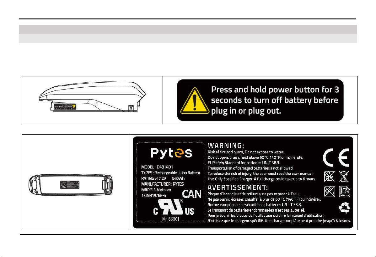
Read and understand all labels on the bike. These labels contain important information for safe and proper bike operation. Do not
remove any labels from the bike. If these labels become difficult to read or peel off, visit VinFast's Distributors and Service
workshops for replacement.
1.
Battery usage guide label
2. Lithium-ion Battery usage caution label
2.1. Location of important labels
2. Safety information
SAFETY INFORMATION
4
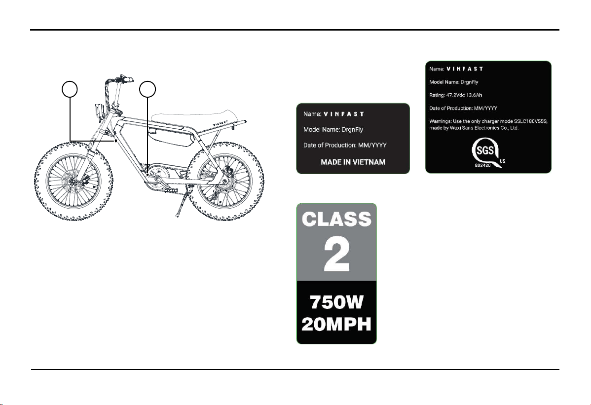
3. Label
A. Marking label 01 & 02
B. Class label
A B

SAFETY INFORMATION
5
2.2.
Safety information
2.2.1.
Safety for the user
Read all the instructions before using the product.
To reduce the risk of injury, close supervision is necessary when the product is used near children
Never ride under the influence of alcohol or drugs.
Before riding, ensure you understand the operation procedures and have proficient riding skills.
Always wear a certified quality helmet.
Use safety equipment when riding:
+ Use dustproof eyewear when riding and a face shield or unobstructed eye protection.
+ Wear bright-colored clothing or reflective gear when riding at night.
Maintain a serious riding posture: Keep both hands on the handlebars, both feet on the pedals, and refrain from using your phone or
listening to music while riding.
Avoid abrupt throttle and acceleration. To maximize braking efficiency, use both brakes gently and avoid sudden braking.
Always obey road traffic safety regulations and speed limits. Pay attention to road conditions and traffic while riding.
Adjust the throttle to match the terrain you are riding on. Gradually apply the throttle when starting.
Be aware of signals from other vehicles and ensure that other road users can see you. Use your bell when necessary. Always use
your lights when riding in low light conditions.

SAFETY INFORMATION
6
Ride cautiously in adverse weather and terrain conditions.
Ensure that you park or stop the vehicle on a flat and secure surface.
In the event of a fire with the electric vehicle, extinguish the fire with a dry powder fire extinguisher. Then, apply other water-based
firefighting methods if necessary.
Riding in adverse weather conditions such as heavy rain or flooding can not only be dangerous for the rider but can also cause
damage to the vehicle's electrical system.
Do not put fingers or hands into the product.
The A-weighted emission sound pressure level at the driver ears is less than 70 dB(A).
2.2.2.
Vehicle Safety
Check the vehicle before operation to ensure the condition of the vehicle and the best driving experience.
Frequently take the vehicle to an authorized dealership for regular inspections and maintenance.
Do not let raincoats or bulky cargo obstruct the lights on the vehicle.
The vehicle structure is designed for only one driver.
Absolutely do not carry passengers or cargo exceeding the vehicle's load capacity.
Operating in wet and flooded road conditions: The engine is designed to be sealed and waterproof, but to ensure safety and engine
longevity, it is recommended to limit operating when the flood level is higher than the motor shaft.
Operating an electric vehicle in extremely hot weather may result in reduced vehicle performance to reduce heat generation.
Lithium-ion batteries will stop operating when the internal battery temperature exceeds 65ºC (149ºF).

SAFETY INFORMATION
7
Your electric bike is designed only for use on paved roads or flat surfaces. Therefore, you should not ride on stairs, jump, perform
wheelies, or engage in similar actions.
Electric bikes are not designed for participating in races or competitions.
Do not add any electrical devices to the vehicle without VinFast's permission. These devices may damage the vehicle, interfere with
the normal operation of other vehicle components, or significantly reduce the vehicle's range or the lifespan of the lithium-ion battery.
Do not use this product if the flexible power cord or output cable is frayed, has broken insulation, or any other signs of damage.
This equipment is not intended to be used at ambient temperatures less than -10°C (14°F) or above ambient temperatures of 45°C
(113°F).
The battery is intended to be charged when the ambient temperature is between 0°C (32°F) and 45°C (113°F). Never charge the
battery when ambient temperatures are outside this range.
2.2.3.
Fire Safety and Environmental Protection
Comply with all legal regulations when disposing of used batteries.
Do not attempt to repair the battery yourself in case of a malfunction; instead, take it to the nearest VinFast service center for
repairs.
Do not place the vehicle near flames or heat sources such as stoves or heaters, as this can cause the battery to become extremely hot
and potentially catch fire or explode.
Do not crush or puncture the battery. Avoid applying excessive pressure to the battery, as this can lead to internal short-circuits and
potential fire or explosion hazard.
ASSEMBLY OF THE BIKE
8
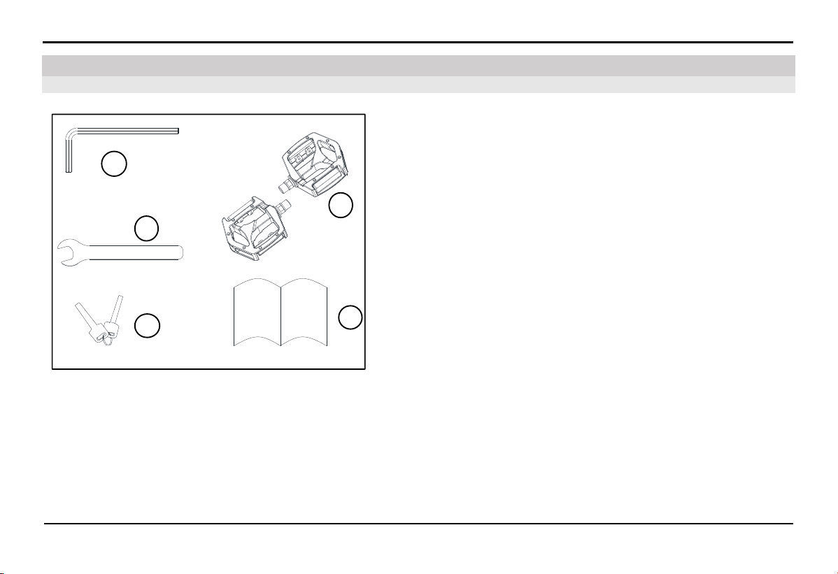
1: Hex key
2: Wrench
3: Battery key
4: Pedal
5: User manual
1
2
3
4
5
3.1. Components in the Box
3. Assembly of the bike
ASSEMBLY OF THE BIKE
9
3.2.
Bike assembly Instructions
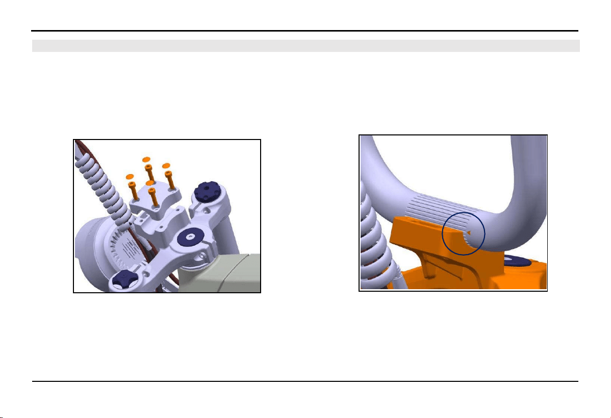
3.2.1.
Handlebar Assembly
1. Remove the 4 cap nuts, 4 bolts, and the handlebar clamp one
by one.
2. Place the handlebar in the correct position and align it so
that the triangle mark engraved on the handlebar is in line
with the top face of the clamp.
ASSEMBLY OF THE BIKE
10
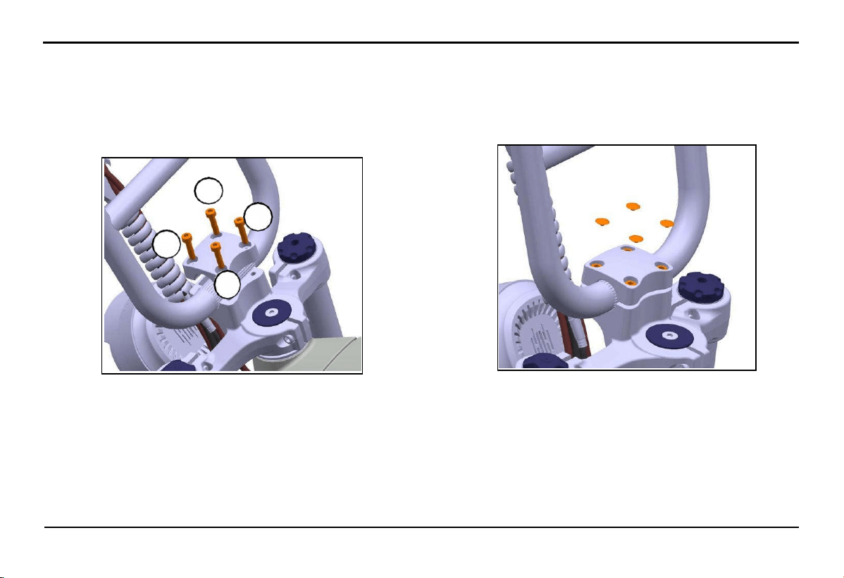
2.
Assemble the handlebar clamp and insert the 4 bolts M5xL20
by hand. Use the hex key (1) to tighten the bolts in the following
sequence: 1>3>4>2.
- Standard tightening force: 6.0 - 8.0 Nm.
3.
Reinstall the 4 bolt caps.
2
3
1
4
ASSEMBLY OF THE BIKE
11
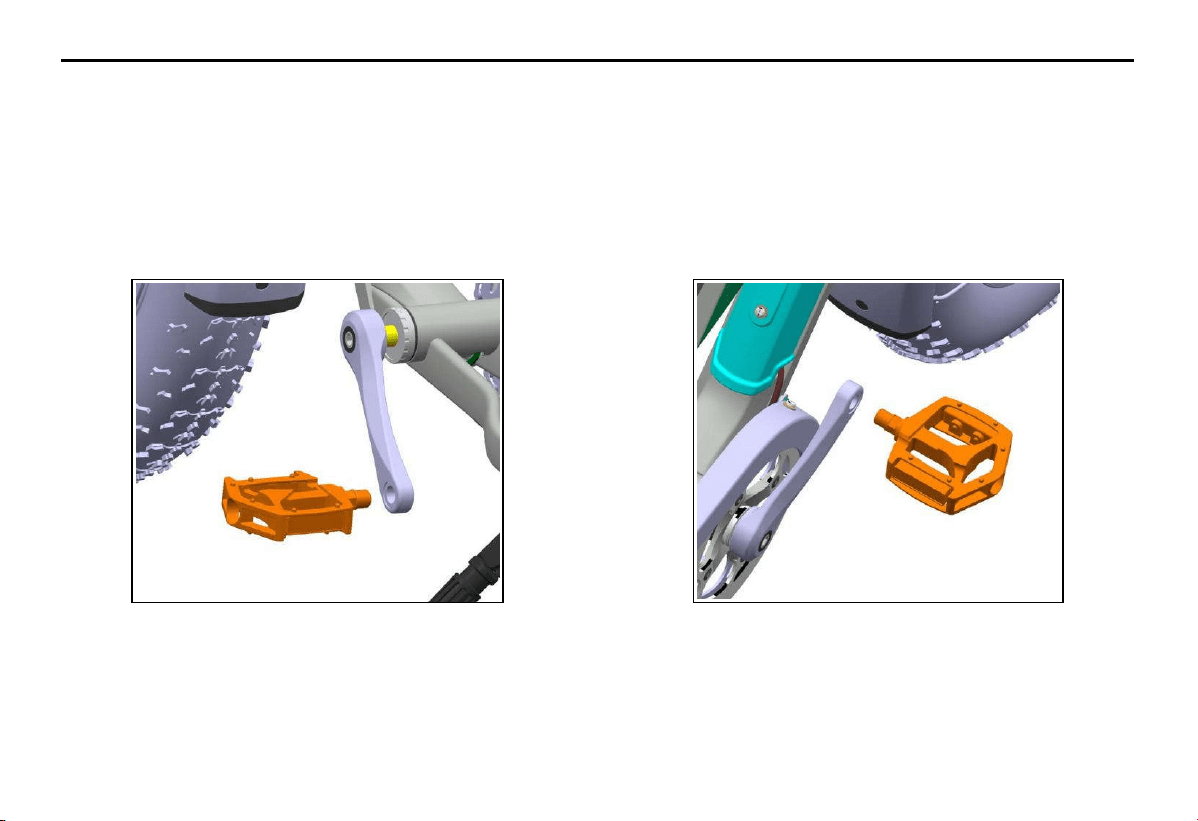
3.2.2.
Pedal Installation
1. Choose the pedal with the "L" mark on the spindle to install
on the left side of the bike, according to the direction of the
rider. Use your hand to thread the pedal into the crank, and
then use the wrench (2) to tighten the pedal securely.
- Standard tightening force: 30 - 40 Nm.
2. Similarly, choose the pedal with the "R" mark on the spindle
to install on the ri
ght side of the bike, according to the direction
of the rider. Use your hand to thread the pedal into the crank,
and then use the wrench (2) to tighten the pedal securely.
- Standard tightening force: 30 - 40 Nm.
ASSEMBLY OF THE BIKE
12
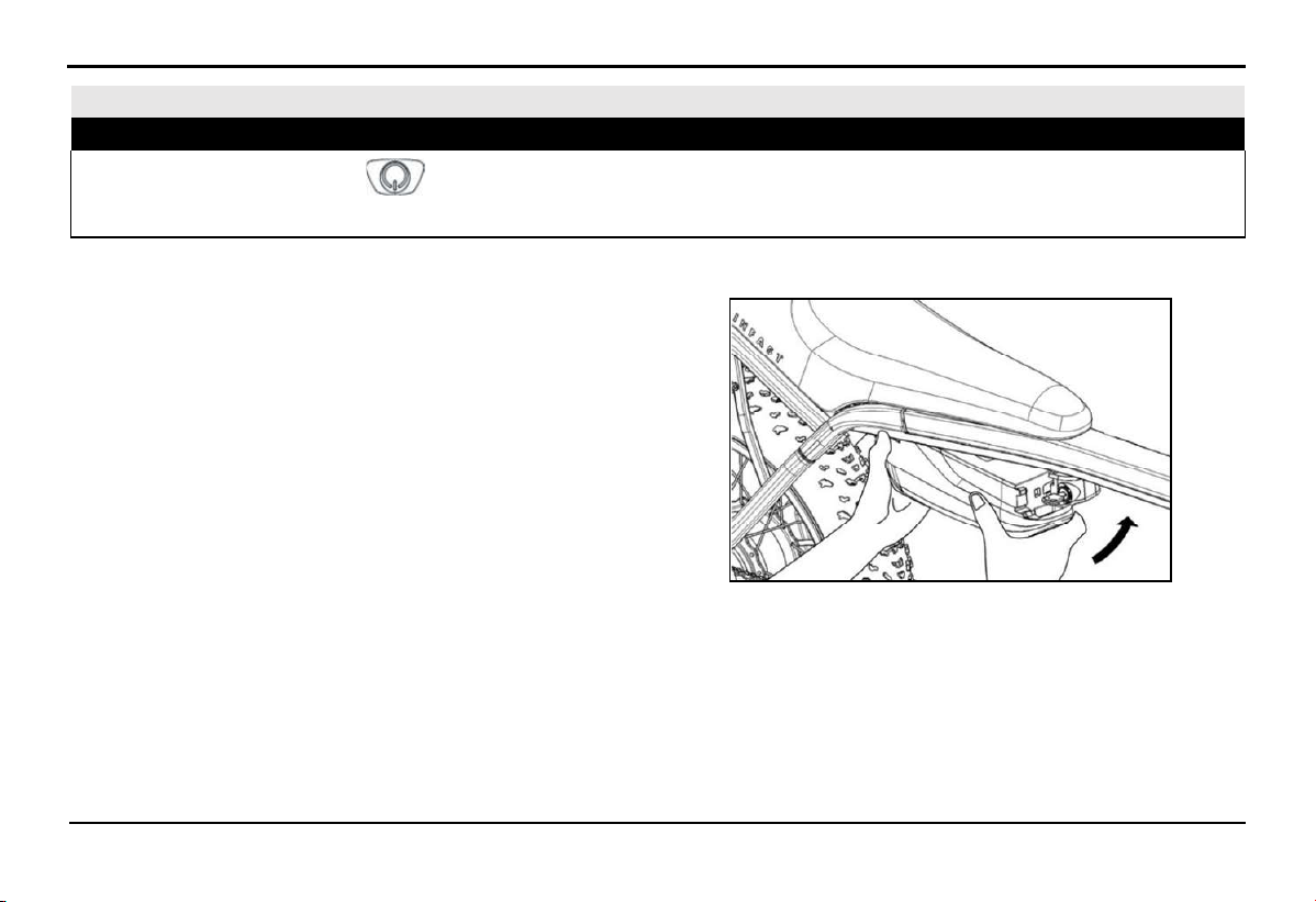
3.3. Removing and Installing Lithium-ion Battery
⚠ WARNING!
Press and hold the power button on the battery for about 3 seconds until the LED light blinks before removing or installing
the battery on the bike. Refer to the detailed information on the warning label attached to the battery.
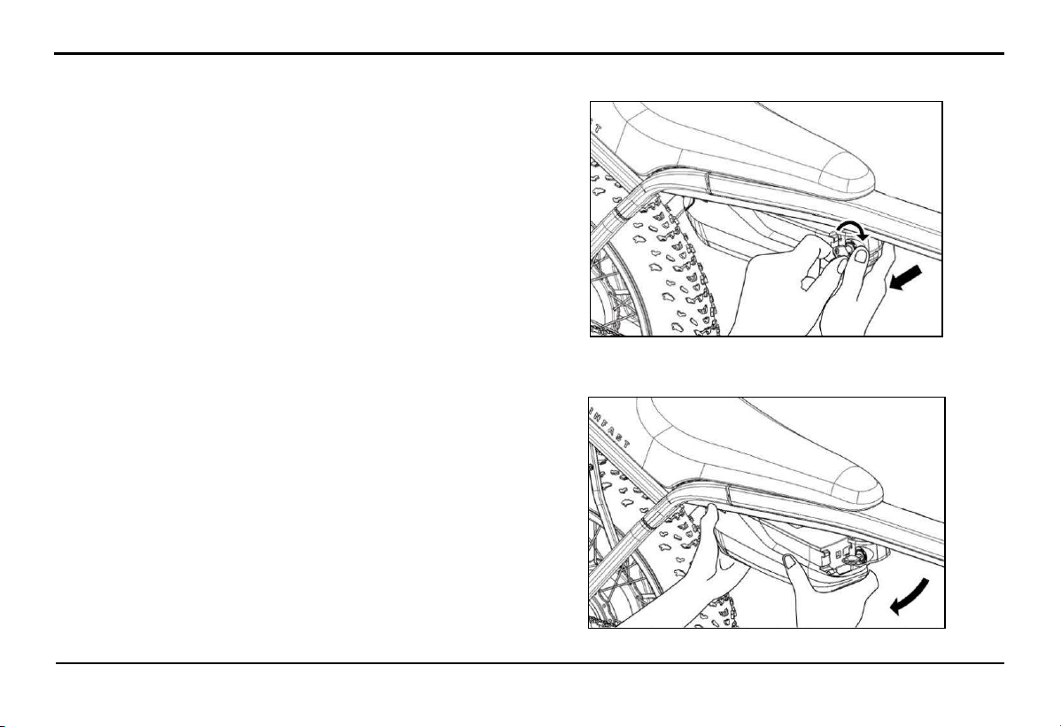
3.3.1.
Installing the battery on the bike
1.
Secure the bike and have the operator stand on the right
side of the bike in the opposite direction of the battery lock.
2.
Hold the battery pack with both hands and insert the battery
tail into the slot.
3.
Align the grooves and slots on the battery pack with those
on the lock.
4.
Use your left hand to support the lower part of the battery
pack, and use your right hand to push the battery head into
the locking mechanism in the direction of the arrow from
the outside in. When you hear the "click" sound, it indicates
that the battery is fully engaged.
ASSEMBLY OF THE BIKE
13
3.3.2.
Removing the Battery from the Bike
1.
Ensure the bike is securely parked, and the operator is
standing on the right side of the bike facing the battery
lock.
2.
Rotate the key clockwise using your left hand while gently
pushing the battery head out of the socket with your right
hand.
3.
Using both hands, support and remove the battery from the
bike in the direction indicated by the arrow.
EXPLORE THE BIKE'S FEATURES
14
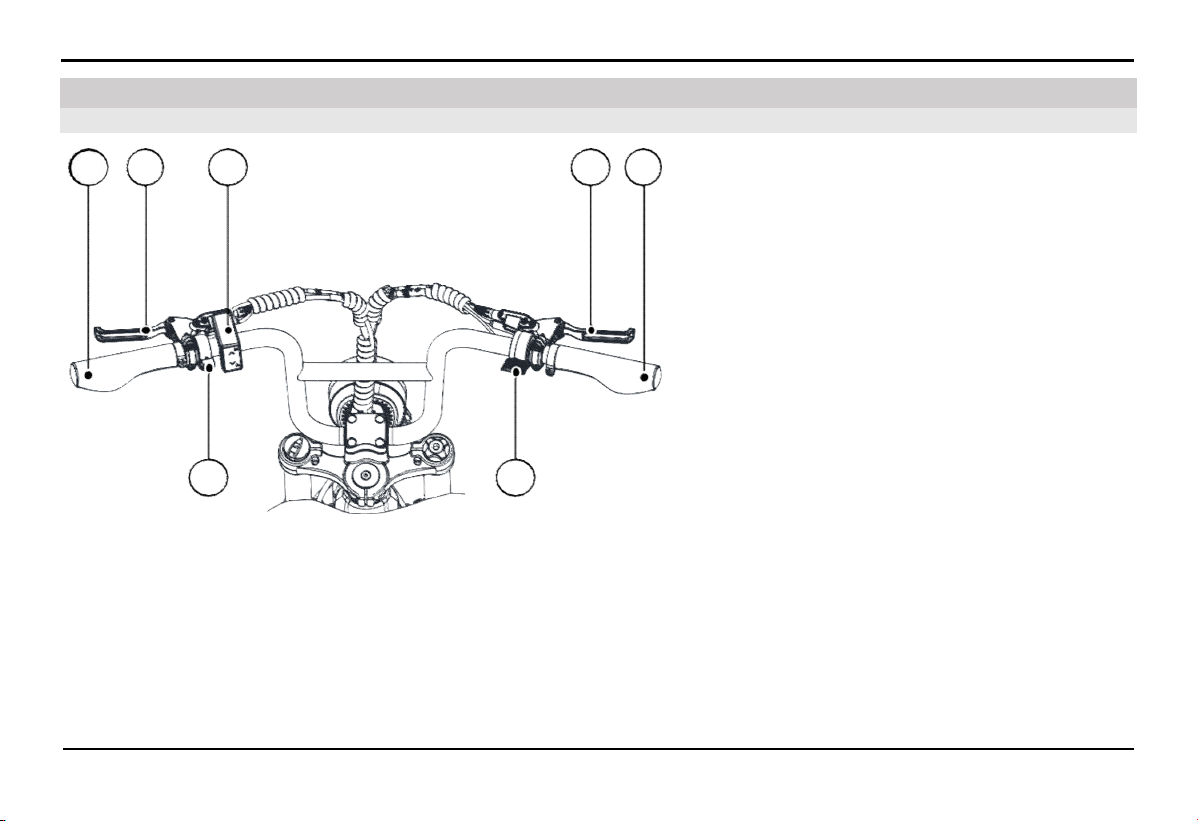
A.
Left Handlebar
B.
Left Brake Lever - Controls the rear brake
C.
HMI Display
D.
Right Brake Lever - Controls the front brake
E.
Right Handlebar
F.
Throttle
G.
Bike Bell
4.1. Rider's Perspective
4. Explore the Bike's Features
A B
C
D E
G
F
15
EXPLORE THE BIKE'S FEATURES
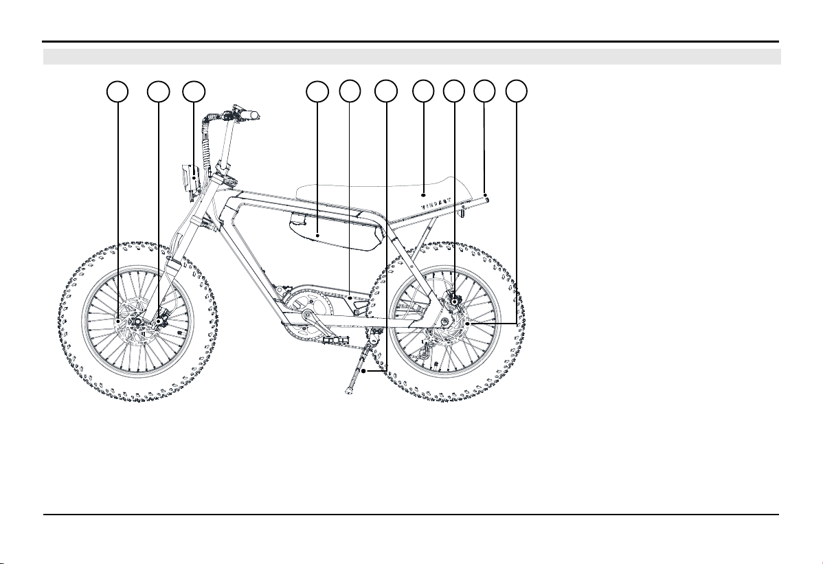
4.2.
Left View
A. Front Brake Disc
B. Front Brake Assembly
C. Front light
D. Battery Pack
E. Bicycle Chain
F. Side stand
G. Bike Saddle
H. Rear Brake Assembly
I. Rear light
K. Rear Brake Disc
HE
D
I
CA
G K
B
F
EXPLORE THE BIKE'S FEATURES
16
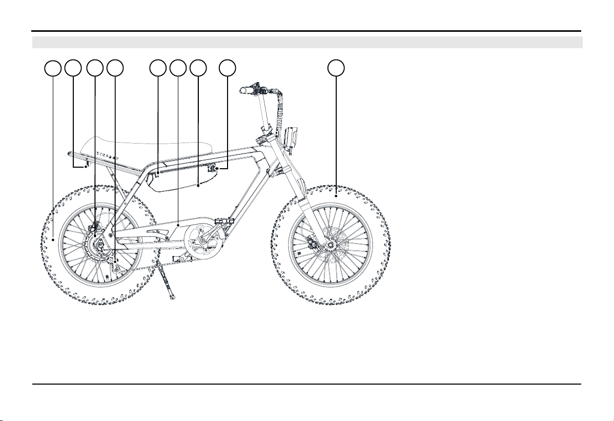
4.3.
Right view
A. Rear Wheel
B. Reflector
C. Motor
D. Chain Tensioner
E. Battery Charging Port
F. Chain Guard
G. Battery Switch, located under
the battery block.
H. Battery Lock
I. Front Wheel
IC ED G
A
B
H
F
EXPLORE THE BIKE'S FEATURES
17
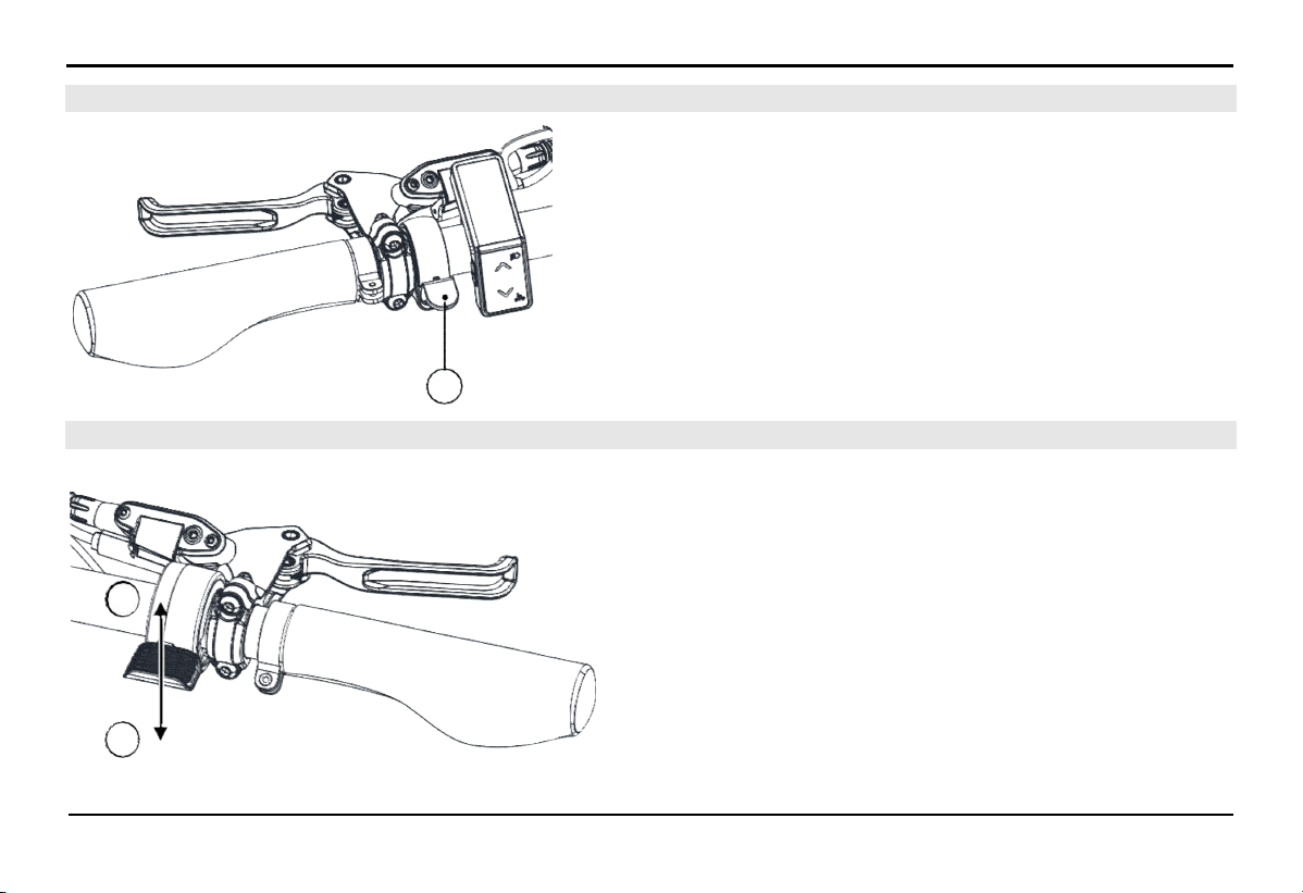
4.5. Electric Throttle (For electric bikes equipped with an electric throttle)
The electric bike operates fairly quietly, so it's important to pay
attention and use the bell when necessary to alert other vehicles
and pedestrians.
Use your thumb to press the bell lever (A) downwards and then
release it quickly to create the sound of the bike bell.
In the initial idle position, the electric throttle can only be pushed
down in the (A) direction.
Pushing the electric throttle in the (A) direction will provide
power to the electric motor, propelling the bike forward. The
energy supplied to the electric motor is proportional to the extent
the electric throttle is pushed.
When the throttle is pushed in the (A) direction and then released
in the opposite direction (B), the energy supplied to the electric
motor decreases, and the bike's speed decreases accordingly.
When the bike is in motion and the electric throttle is released to
its initial state, the motor will not consume energy, and the bike
will continue to move due to inertia.
4.4. Bike bell
A
B
A
EXPLORE THE BIKE'S FEATURES
18
4.6.
Disc Brakes
The bike is equipped with disc brakes both at the front and rear wheels.
+ Always squeeze both brake levers evenly when you need to reduce speed or stop the bike
+ The right brake lever activates the front brake, and the left brake lever activates the rear brake
⚠ WARNING!
The brake discs will become hot during use and for a short period after use. To avoid burns, please do not touch the brake disc
immediately after use
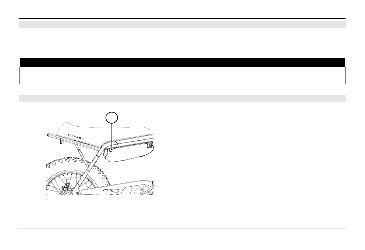
4.7.
Charging port
The electric charging port (A) for the bike is located on the
battery block, and it has a protective cover to prevent water from
entering.
Be sure to close the charging port cover carefully after removing
the charger from the bike.
A
EXPLORE THE BIKE'S FEATURES
19
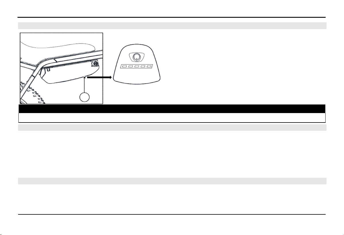
4.8.
Battery switch
The battery switch (A) is located beneath the battery block.
Press the switch once to turn on the battery.
Press and hold the battery switch for about 3 seconds (s) until
the LED light flashes to turn off the battery.
Next to the switch, there is an LED indicator bar to display the
remaining battery power. Each battery bar represents 20%
capacity. When the battery capacity is less than 5%, the LED light
will flash red.
⚠ WARNING!
Always turn off the battery when installing or removing it from the bike.
4.9.
Front lights and rear lights
The vehicle is equipped with front lighting, including position lights and low-beam headlights. The rear lights include rear position
lights and brake lights. The lighting system is designed to automatically turn on/off when you turn on/off the vehicle's electrical
system and the light icon is always illuminated on the HMI.
Note: The front light housing temperature will increase during operation. Avoid touching the metal headlight housing directly during
and after the headlight operation.
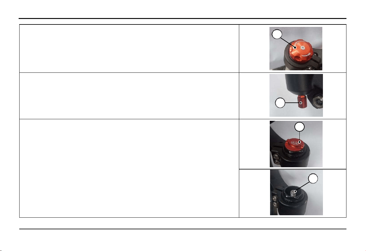
4.10.
Front shock absorber setting
The front shock absorber is an air shock absorber system, which allows users to manually adjust parameters such as stiffness, rebound
speed, and compression speed to achieve the most comfortable riding experience.
A
EXPLORE THE BIKE'S FEATURES
20
+ Adjusting Stiffness: Rotate cap A clockwise to increase the stiffness of the
absorber and rotate counterclockwise to decrease the stiffness. The stiffness level of
the absorber depends on the position of cap A set by the user.
A
+ Adjusting the rebound speed: Loosen the screw B to adjust the rebound speed as
desired. Screw B can be loosened up to a maximum of 3 turns but cannot be
completely removed from the shock absorber.
B
+ Inflating the shock absorber with air: Remove the cap C by turning it
counterclockwise. Then, add air to the shock absorber through valve head D.
The air pressure should be adjusted according to the rider's weight, typically
around 110-130 psi.
C
D
EXPLORE THE BIKE'S FEATURES
21
4.11.
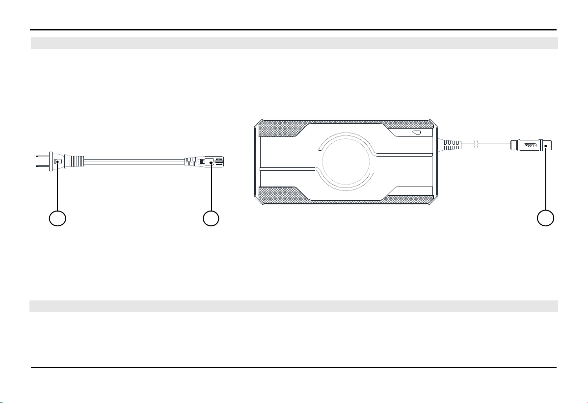
Included Charging Kit
The charger is designed for indoor use, always charge the electric bike in a well-ventilated area and away from flammable materials.
Only use the charger provided with the bike or an equivalent charger supplied by VinFast when charging. Using the wrong charger
can damage the electrical system of the bike and lead to unwanted fire hazards.
The supplied charger, rated at 54.6V/3A, consumes a maximum electrical power of about 150W from an AC power source of
100~240V/50~60 Hz.
A.
Plug for AC power (100~240V/50~60 Hz)
B.
Plug for connecting to the charger
C.
Output plug into the charging port on the bike (DC)
Note: Use the only charger model SSLC180V55S made by Wuxi Sans Electronics Co., Ltd.
4.12. Charging the bike
The maximum temperature inside the Lithium-ion battery while charging is 45°C (113⁰F). If the temperature inside the battery
exceeds this threshold, the battery will refuse to charge until the temperature is lowered. The temperature inside the Lithium-ion
battery can reach up to 60°C (140⁰F) during heavy use, even though the ambient temperature is lower.
BA C

EXPLORE THE BIKE'S FEATURES
22
The refusal to charge by the Lithium-ion battery is a self-protection feature to extend its lifespan. Charging at high temperatures can
reduce the lifespan of Lithium-ion batteries.
Lithium-ion batteries perform best within a temperature range of 10°C (50⁰F) to 40°C (104⁰F). It's not advisable to charge the battery
when the battery temperature is ≥ 45°C (113⁰F). After using the bike, it's recommended to wait for about one hour to allow the
battery's internal temperature to decrease, which can help prolong the battery's lifespan.
NOTE: Maintaining the battery capacity within the range of 20% to 80% is better for the lifespan of Lithium-ion batteries Don't
hesitate to charge the bike when needed (check the battery capacity in section 4.8).
Charging status information is updated on the HMI and smartphone app if connected.
During the charging process, the throttle and motor will not operate.
4.12.1.
Battery Charging Procedure on the Bike
1.
Open the charging port cover.
2.
Connect the DC end (C) of the charger to the charging port, and the end (B) into the charger body.
3.
Plug the AC end (A) of the charger into an electrical outlet.
4.
Observe the charger; the light turning red indicates the charging process has started.
4.12.2.
Battery Charging Procedure Off the Bike
1.
Unlock and remove the battery from the bike (Refer to the battery removal instructions).
2.
Open the charging port cover.
3.
Connect the DC end (C) of the charger to the charging port, and the end (B) into the charger body.
4.
Plug the AC end (A) of the charger into an electrical outlet.
5.
Observe the charger; the light turning red indicates the charging process has started.

EXPLORE THE BIKE'S FEATURES
23
NOTICE:
You should connect the charger plug to the bike first and then plug it into the electrical outlet. Ensure a firm connection to prevent
loose connections, which may trigger the charger's self-protection feature. In case of a loose connection, unplug the charger and plug
it back in to ensure a stable connection
To disconnect the charger: Remove the electrical plug first, and then unplug the charger plug.
4.12.3.
Charger Indications
The charger uses lights to indicate its status:
Red light illuminated: Charging in progress.
Green light illuminated: Battery is full, or the charger is not connected to the bike.
4.12.4.
Usage Tips
If the green light is on, it means the battery is fully charged. Disconnect the AC plug and then unplug the charger.
After a Lithium-ion battery is fully charged to 100%, it continues to charge with a small current until the light turns green to help
the battery achieve maximum capacity and extend its lifespan.
If the HMI display doesn't light up after turning on the bike, press the power button on the battery to activate it.
4.13.
Lithium-ion Battery
4.13.1.
Overview of Lithium-ion Battery
The Lithium-ion battery is located under the saddle and can be removed from the bike.
Safety information:
Do not attempt to disassemble or open the inside of the battery or subject the battery to physical stress (even if the battery is
damaged).

EXPLORE THE BIKE'S FEATURES
24
Avoid short-circuiting the battery: Keep conductive objects away, prevent water from entering the battery area.
Storing or long-term parking in high environmental temperatures above 45°C (113°F) or in direct sunlight can be unsafe and reduce
the performance of the Lithium-ion battery.
Usage information:
Battery capacity will naturally decrease over time due to natural degradation.
Do not use batteries from other models or make unauthorized modifications to the battery, as this can damage the electrical
components of the vehicle.
Overloading the vehicle beyond its allowed capacity can cause swelling and reduce the battery's lifespan.
When the vehicle is turned off, the vehicle's electronic systems still consume a small amount of energy, and the battery capacity
will gradually decrease over time.
After use, if the battery capacity drops below 20%, you should recharge it within 3 days.
The battery will automatically power off after a period of inactivity. Press the power button on the battery to turn it on before use.
Always remove the battery from the vehicle when performing maintenance or servicing.
Storage instructions
If you plan to store your bike for more than 14 days, follow these instructions to ensure the quality and lifespan of your battery.
Charge the battery to 50%, then press and hold the button on the bottom of the battery for 3 seconds to turn off the battery.
Store the battery indoors in a cool, dry place with a temperature range of 0°C (32°F) to 40°C (104°F).
Check the battery capacity periodically once a month and recharge the battery to 50%.
NOTICE: Do not store the bike with a battery capacity below 20%. Storing the battery with a capacity below 20% for an extended
period can potentially lead to complete battery damage and may void the warranty.

EXPLORE THE BIKE'S FEATURES
25
4.13.2.
Lithium-ion Battery Management System
Each Lithium-ion battery is equipped with a Battery Management System (BMS) to monitor the battery's operational status and
optimize the charging process for the best performance and maximum battery life.
The BMS has multiple protection functions to prevent potential battery damage. When these protection functions are activated, the
battery may stop responding and cut off the output power.
The BMS operates continuously while the user is driving and when the vehicle is stored.
In case of any issues with the Lithium-ion battery, please contact the Distributors and Service workshops of VinFast for assistancess.
EXPLORE THE BIKE'S FEATURES
26
Hiển t hị d ung lượng p in
Chỉ b áo đ èn
Phím b ật t ắt ng uồn
Hiển t hị t ốc độ xe
Hiển t hị t hông số
Hiển t hị chế độ t rợ lực
Phím
chức năng
Phím d i chuyển lên xuống
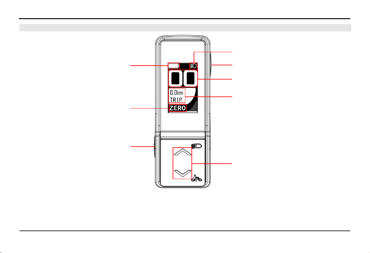
4.14.
Multi-Function Display Screen (HMI)
Battery capacity display
Assist mode display
Function buttons
Indicator light
Power on/off
button
Speed display
Parameter display
Up and down buttons
EXPLORE THE BIKE'S FEATURES
27
4.14.1.
Battery capacity bar
The capacity bar is displayed at the top of the HMI screen. The capacity bar provides information about the remaining
battery capacity. When the battery loses connection with the system, the capacity bar will flash red.
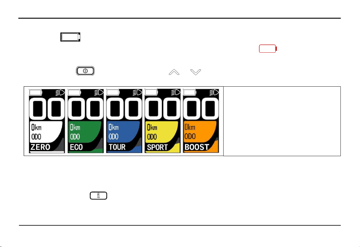
4.14.2.
Assist mode display
After pressing button to start the screen, press the or to change the selection of assistance modes, there are 5
modes: ZERO/ECO/TOUR/SPORT/BOOST.
The level of assistance increases gradually in the following order ECO > TOUR > SPORT > BOOST, with ZERO mode
providing no assistance. Additionally, within each assistance mode, the level of assistance depends on the speed and force applied
to the pedal by the rider.
4.14.3.
Parameter display
In each mode, press button repeatedly to view the following parameters ODO -> Trip -> Time -> AVG -> MAX -> M PWR
-> H PWR -> CONS -> C.INST -> RANGE -> PD RPM.
+ ZER0: No assistance
+ ECO: Eco mode
+ TOUR: Long-distance mode
+ SPORT: Sport mode
+ BOOST: Acceleration mode
EXPLORE THE BIKE'S FEATURES
28
The meaning of the displayed parameters:
ODO: Total distance traveled
TRIP: Distance of a single trip
TIME: Time of a single trip (in hours and minutes)
AVG: Average cycling speed
MAX: Maximum cycling speed
M PWR: Motor power
H PWR: Pedal power
CONS: Overall vehicle power consumption
C. INST: Direct motor power consumption
RANGE: Estimated remaining range the vehicle can travel
PD RPM: Pedal revolutions per minute
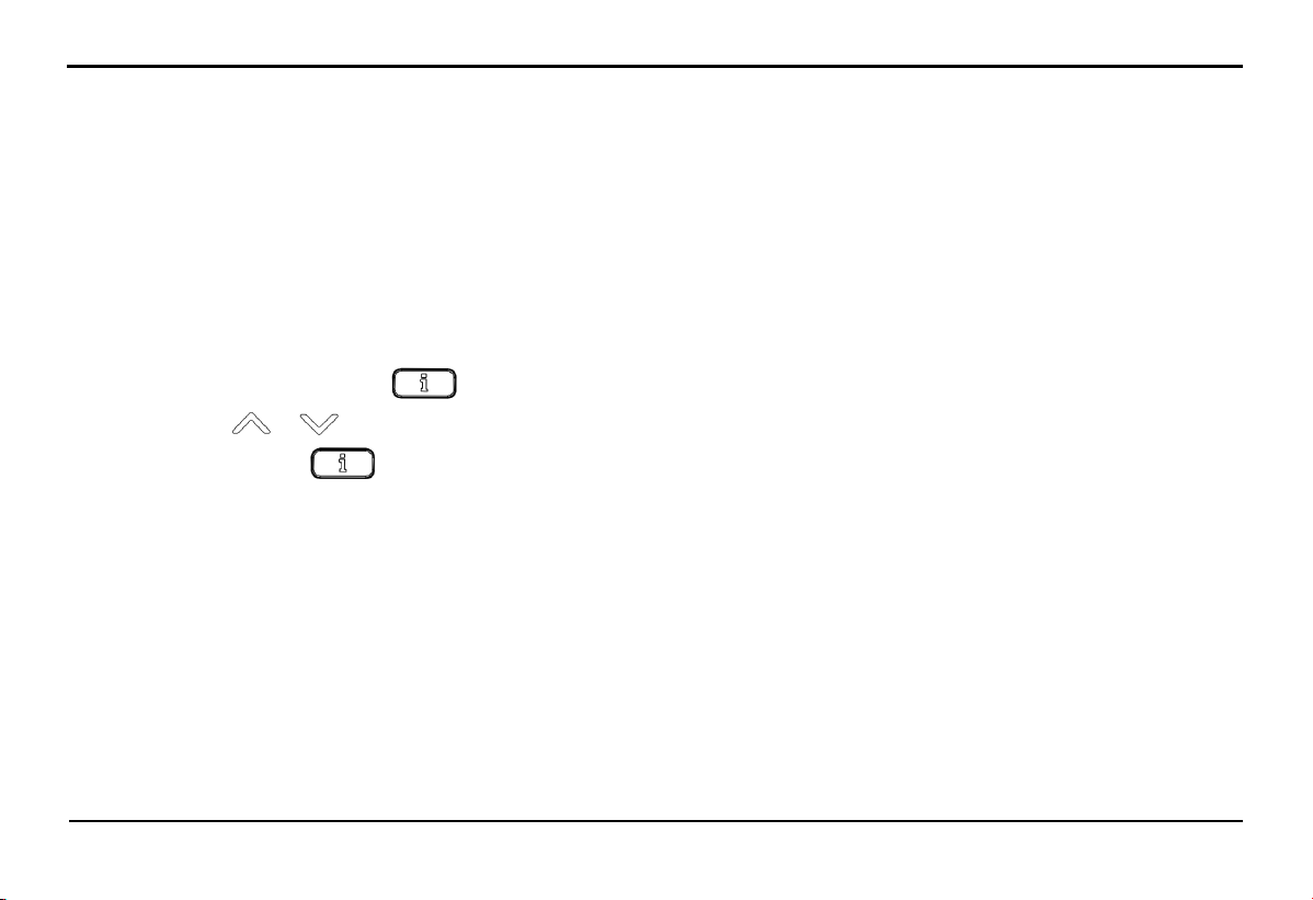
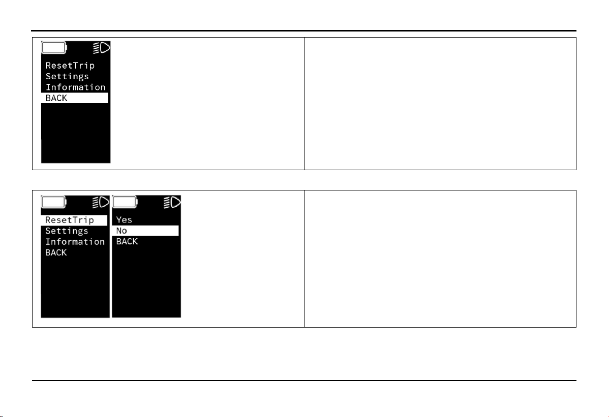
4.14.4.
Setting Parameters on the Screen
Press and hold the function button for about 5 seconds, the screen will enter the settings menu.
Press the button or to select the settings content.
Press the function button
Select BACK to returns.
once to select the parameter.
EXPLORE THE BIKE'S FEATURES
29
+ ResetTrip: Reset TRIP and TIME values
+ Settings: Screen settings
+ Information: Displays product information
+ BACK: Return to the main screen
Select ResetTrip to reset the trip.
+ Yes: Select
+ No: Not select
+ BACK: Return to the previous screen
EXPLORE THE BIKE'S FEATURES
30
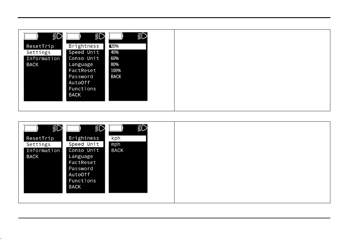
Select Settings -> Brightness to select screen brightness.
+ 20%: Brightness 20%
+ 40%: Brightness 40%
+ 60%: Brightness 60%
+ 80%: Brightness 80%
+ 100%: Brightness 100%
+ BACK: Return to the previous screen
Select Settings -> Speed Unit to choose Speed Unit.
+ kph: Choose to display in kilometers per hour
+ mph: Choose to display in miles per hour
+ BACK: Return to the previous screen
EXPLORE THE BIKE'S FEATURES
31
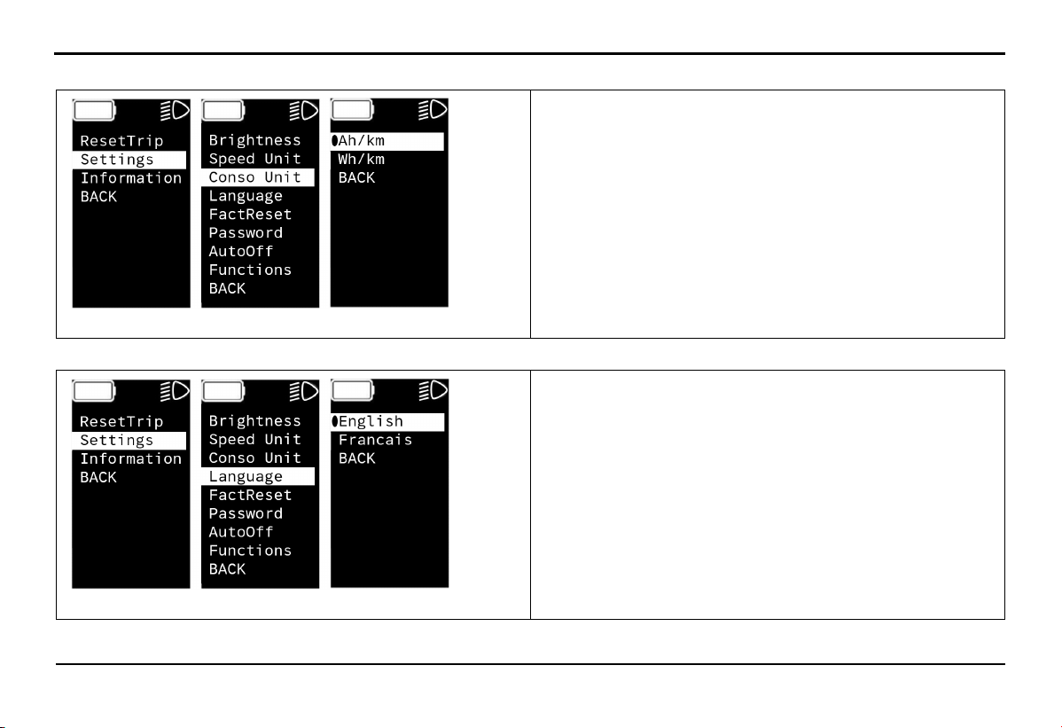
Select Settings -> Conso Unit to choose the energy consumption display unit.
+ Ah/km: Choose to display ampere hours/kilometers
+ Wh/km: Choose to display watt hours/kilometers
+ BACK: Return to the previous screen
Select Settings -> Language to choose language.
+ English: choose English language
+ Francais: choose French language
+ BACK: Return to the previous screen
EXPLORE THE BIKE'S FEATURES
32
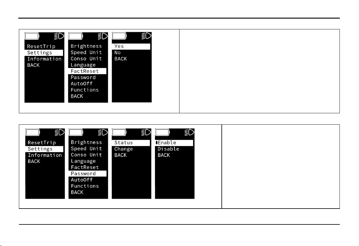
Select Settings -> FactReset to restore original factory settings.
+ Yes: Select
+ No: Not select
+ BACK: Return to the previous screen
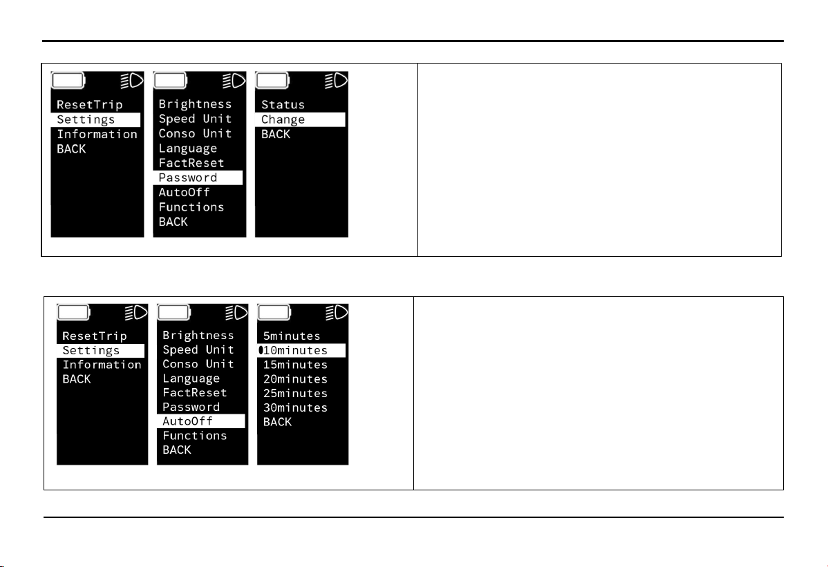
Select Settings -> Password -> Status to cancel or activate the password.
+ Enable: Activate
+ Disable: Cancel
+ BACK: Return to the previous screen
33
Select Settings -> Password -> Change to change the screen password.
EXPLORE THE BIKE'S FEATURES
+ Change: Input new password
Note: You must enter the old password before entering
the new password
Select Settings -> AutoOff to set to automatically turn off the HMI screen.
+ 5 minutes: Turns off after 5 minutes
+ 10 minutes: Turns off after 10 minutes
+ 15 minutes: Turns off after 15 minutes
+ 20 minutes: Turns off after 20 minutes
+ 25 minutes: Turns off after 25 minutes
+ 30 minutes: Turns off after 30 minutes
+ BACK: Return to the previous screen
34
EXPLORE THE BIKE'S FEATURES
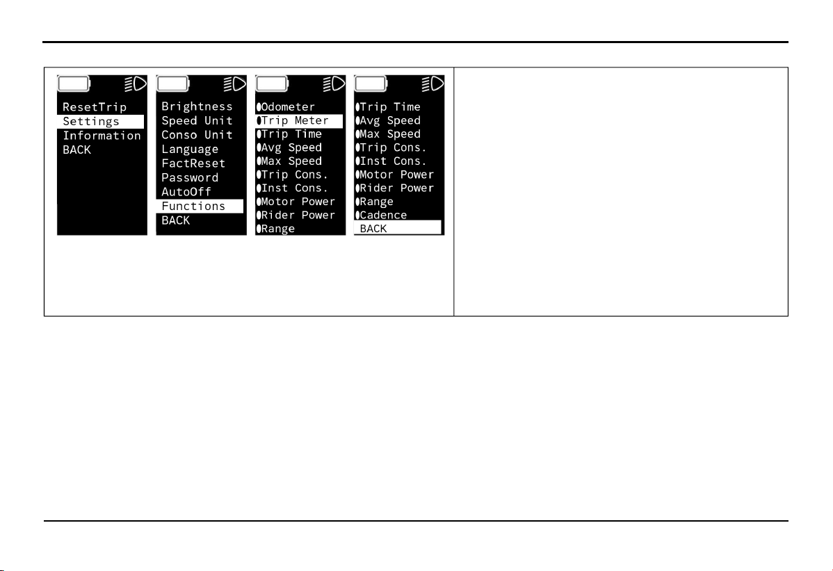
Select Settings -> Functions to select the parameters displayed on the screen.
+ Odometer: Total distance traveled
+ Trip Meter: Distance of a single trip
+ Trip Time: Time of a single trip (hours and minutes)
+ Avg Speed: Average cycling speed
+ Max Speed: Maximum cycling speed
+ Trip Cons: Overall energy consumption of the vehicle
+ Inst Cons: Direct motor power consumption
+ Motor Power: Motor power output
+ Rider Power: Pedal power output
+ Range: Estimated remaining range of the vehicle
+ Cadence: Displays PD RPM parameters
+ BACK: Return to the previous screen
EXPLORE THE BIKE'S
FEATURES
35
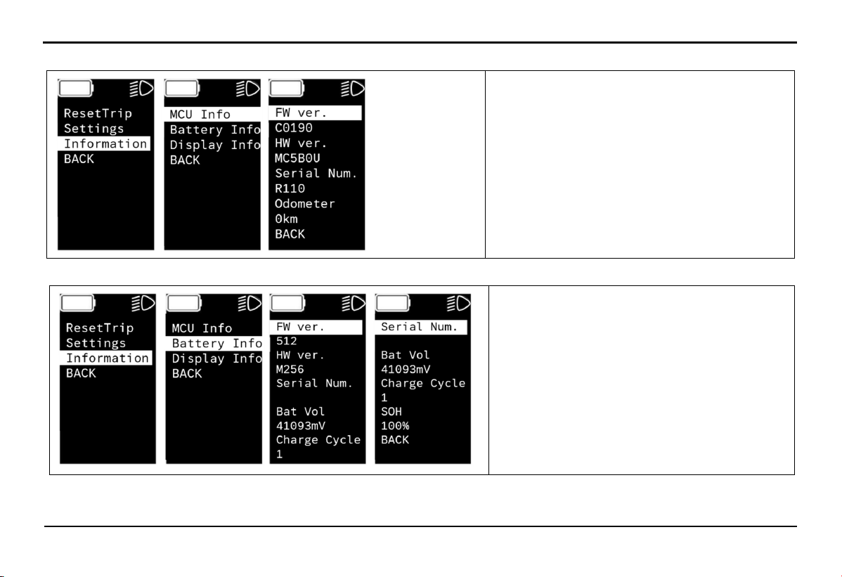
Select Information -> MCU Info to see motor information.
+ FW ver: Motor control unit software version
+ HW ver: Motor control unit hardware
version
+ Serial Num: Serial number
+ Odometer: Total distance traveled
+ BACK: Return to the previous screen
Select Information -> Battery Info to see battery information.
+ FW ver: Battery software version
+ HW ver: Battery hardware version
+ Serial Number: Serial number
+ Bat Vol: Battery voltage
+ Charge Cycle: Charge cycle count
+ SOH: Remaining battery life
+ BACK: Return to the previous screen
36
EXPLORE THE BIKE'S FEATURES
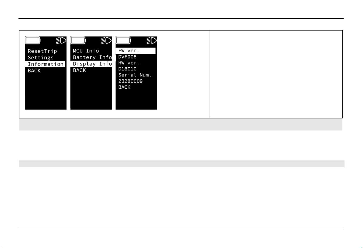
Select Information -> Display Info to see HMI screen information.
+ FW ver: Display software version
+ HW ver: Display hardware version
+ Serial Num: Serial number
+ BACK: Return to the previous screen
4.15. Mobile application
The mobile app supports users in connecting with the vehicle and performing advanced tasks.
The mobile app is always available on the App Store and Google Play Store, and you can download and install it for free to explore
additional premium features.
4.16. Software Update
Over-the-Air (OTA) software updates are integral to evaluating the overall operating experience of your e-Bike, and to enable it to
become better equipped over time, providing essential safety, performance, feature enhancements and bug fixing efficiently and
securely. These updates might therefore include minor enhancements or improvements to performance, maintainability, and
serviceability that play a vital role in ensuring your e-Bike performs at its optimal level throughout its life cycle.
We continuously strive to improve performance and enhance product security. By receiving OTA software updates, your e-Bike stays
current and is less susceptible to known vulnerabilities. You must only accept OTA software updates from VinFast or approved
sources.

37
EXPLORE THE BIKE'S FEATURES
Certain critical updates regarding safety and security will be installed without your confirmation. For these, we will notify you via the
"VinFast e-Bike mobile application” or send a text to your registered phone number. Typically, this notice will be received about 3
days in advance, unless exceptional circumstances necessitate a shorter notice period.
STARTUP AND OPERATION
38
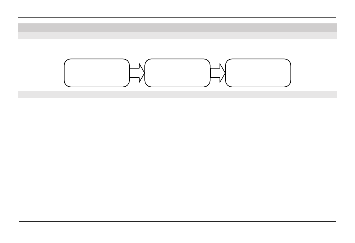
Kiểm
t ra
t rước khi vận hành
Mở khóa
hệ t hốn g đi
ện
Vận hành
xe đ iện của bạn
Pre-operation check
Turn ON the bike
Operating your electric
bike
5.2. Pre-operation check
The basic operations when operating your electric bike briefly described in the diagram below. Please proceed to the detailed
instructions for each part as per the guide to learn more details.
Before operating your electric bike, please pay attention to check the following points:
Lithium-ion battery: Check the battery capacity to ensure there is enough energy for your upcoming journey.
Brakes: Squeeze the brake lever and test pushing the vehicle forward and backward to check the brake responsiveness. Ensure that
the brakes are functioning properly.
Electric throttle: Turn off the HMI, try pushing down and releasing the electric throttle to check for smooth operation and its return
to the original position.
Tires: Check the tire pressure and wear on both tires to ensure safety.
Electrical system: Check the functioning of the front lights, HMI display, and rear lights.
5.1. Basic operation
5. Startup and Operation
39
STARTUP AND OPERATION
5.3.
Turn on/off the bike's electrical system
5.3.1.
Turn ON the bike
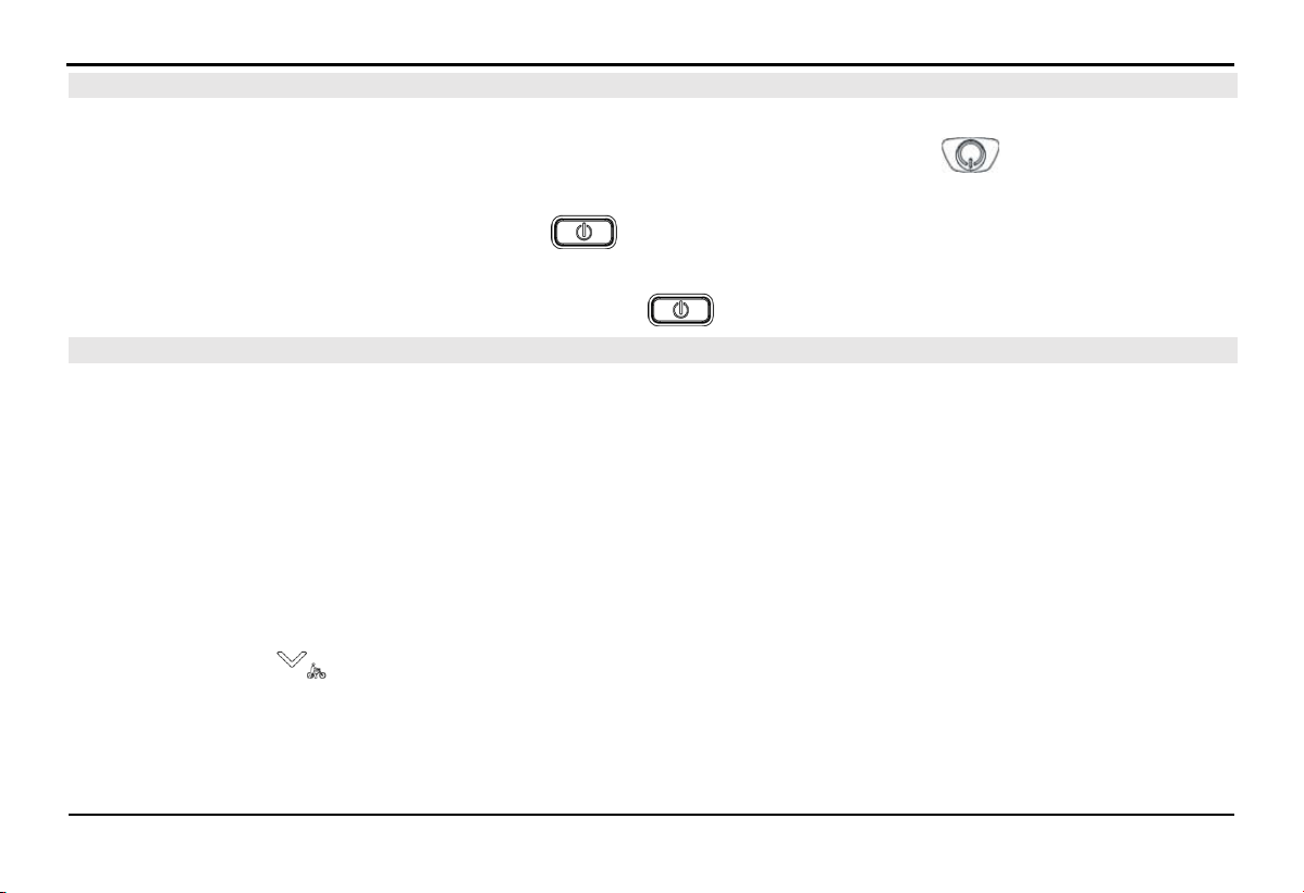
Note: The battery will automatically power off after a period of inactivity. Press the power button on the battery to turn it on
before use.
The vehicle is in the OFF state. Press the power button on the HMI once to activate the vehicle's electrical system.
5.3.2.
Turn off the bike
While the bike is in the ON state, press and hold the power button on the HMI to turn off the bike.
5.4.
Operating Your Electric Bike
5.4.1.
First-Time Operation
1.
Raise the side stand.
2.
Turn on the bike.
3.
Set the desired assistance modes.
4.
Gradually use the electric throttle or pedal to accelerate the bike.
5.4.2.
Walking Mode
Electric bikes are designed to be heavier than regular bicycles. Therefore, your bike is equipped with a walking mode to assist the
rider when walking the bike.
Press and hold button on the HMI screen to activate walking mode. The bike's speed will be limited to a range of 3-6 km/h.
Release the button to turn off walking mode.

STARTUP AND OPERATION
40
5.4.3.
Zero Assist Mode
In this mode, users pedal the bike like a regular bike. The electric motor is not active.
5.4.4.
Assist Mode
The assist mode utilizes the electric motor's energy to support and reduce fatigue for the rider, increasing travel time and distance.
Riders can set the driving modes ECO/TOUR/SPORT/BOOST through the HMI screen. The level of assistance increases gradually
in the following operating modes: ECO > TOUR > SPORT > BOOST. Additionally, within each assist mode, the level of assistance
depends on the speed and the force applied to the pedals.
5.4.5.
Full Electric Mode (With Electric Throttle)
This is a pedal-free mode applicable to the ECO/TOUR/SPORT/BOOST levels, where the rider doesn't expend bodily energy to
operate the bike. The bike will be entirely powered by the electric motor through throttle control. The distance the bike can travel
depends on the speed and actual operating conditions.
5.4.6.
Braking
Squeeze the handbrake lever and increase pressure to slow down or stop the bike. The right handbrake controls the front wheel brake,
while the left handbrake controls the rear wheel brake. When applying the brakes, it's advisable to release the electric throttle to its
initial position. The system will disengage assistance.
5.4.7.
Stopping/Turning off the Bike
After the bike comes to a complete stop, press and hold the power button on the HMI for about 3 seconds to turn off the bike.
5.4.8.
Parking the bike
Hold the vehicle with both hands and tilt it slightly to the opposite side to easily deploy the side stand.
Notice: Park the vehicle on a level surface.

PERIODIC MAINTENANCE AND ADJUSTMENTS
41
6.1.1.
Recommendations
Regular maintenance and periodic checks are essential to keep your vehicle in its best condition. Properly maintaining your vehicle
is crucial for safe operation and cost-effective repairs. Therefore, it is advisable to inspect your vehicle before each ride and follow
VinFast's recommended maintenance schedule.
VinFast encourages customers to perform maintenance and routine checks at the Distributors and Service workshops of VinFast to
experience quality service.
6.1.2.
Maintenance Schedule
No Maintenance content
The ODO meter reading or usage time, whichever comes first
x 100 km 1 5 10 15 20 25 30 35 40 45 50
Month number 1 3 5 7 9 11 13 15 17 19 21
1 Front/Rear brakes lever C C C C C C C C C C C
2 Brake fluid (visually check) - - - - - C - - - - C
3 Front/Rear pad C C C C C C C C C C C
4 Front/Rear brake hoses C C C C C C C C C C C
5 Lights/Bell/Display C C C C C C C C C C C
6 Throttle C C C C C C C C C C C
7 Side stand C C C C C C C C C C C
8 Lithion-ion battery Charging port C C C C C C C C C C C
6.1. Basic Information
6. Periodic Maintenance and Adjustments

PERIODIC MAINTENANCE AND ADJUSTMENTS
42
No Maintenance content
The ODO meter reading or usage time, whichever comes first
x 100 km 1 5 10 15 20 25 30 35 40 45 50
Month number 1 3 5 7 9 11 13 15 17 19 21
Connecting plug C C C C C C C C C C C
Lock socket C C C C C C C C C C C
External appearance - C C C C C C C C C C
9 Front rim
Runout radial C C C C C C C C C C C
Spokes C C C C C C C C C C C
Front axle bolt C C C C C C C C C C C
Front bearing C C C C C C C C C C C
10 Front tire
Tire tread depth - C C C C C C C C C C
Air pressure C C C C C C C C C C C
11 Headset cup
C C C C C C C C C C C
- - - - L - - - L - -
12 Front shock absorber C C C C C C C C C C C
13
Rear rim
Runout radial C C C C C C C C C C C
Spokes C C C C C C C C C C C
Rear axle bolt C C C C C C C C C C C
Rear bearing C C C C C C C C C C C

PERIODIC MAINTENANCE AND ADJUSTMENTS
43
No
Maintenance
content
The ODO meter reading or usage time, whichever comes first
x 100 km 1 5 10 15 20 25 30 35 40 45 50
Month number 1 3 5 7 9 11 13 15 17 19 21
14 Rear tire
Tire tread depth - C C C C C C C C C C
Air pressure C C C C C C C C C C C
15 Chain L L L L L L L L L L L
16 Chainring C C C C C C C C C C C
17 Rear cog C C C C C C C C C C C
18 Chain tensioner C C C C C C C C C C C
19 Pedal C C C C C C C C C C C
20 Motor - C C C C C C C C C C
Note: C = Check, L = Lubricate
NOTE:
For your safety, it is advisable to take your vehicle to the Distributors and Service workshops of VinFast for inspection and
maintenance.
If the distance displayed on the HMI is greater than the maintenance schedule, repeat the maintenance cycle as mentioned above.
Maintenance should be performed more frequently if you regularly ride in wet, dusty, or off-road conditions, or climb hills…
PERIODIC MAINTENANCE AND ADJUSTMENTS
44
6.2.1.
Check Front and Rear Brakes
It is advisable to periodically check the wear of the front and rear brakes according to the maintenance schedule and lubricate them
regularly.
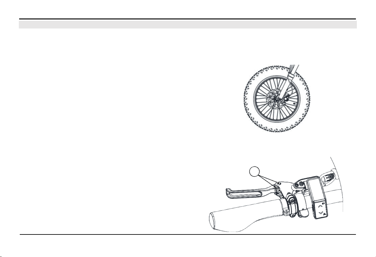
Front/Rear Brake Pads:
To check the wear of the brake pads, observe the thickness of the
brake pads directly through the gap in the brake caliper. If the
brake pads are worn to a thickness of approximately less than 0.65
mm, please bring your vehicle to the Distributors and Service
workshops of VinFast to have the brake pads replaced with a new
set.
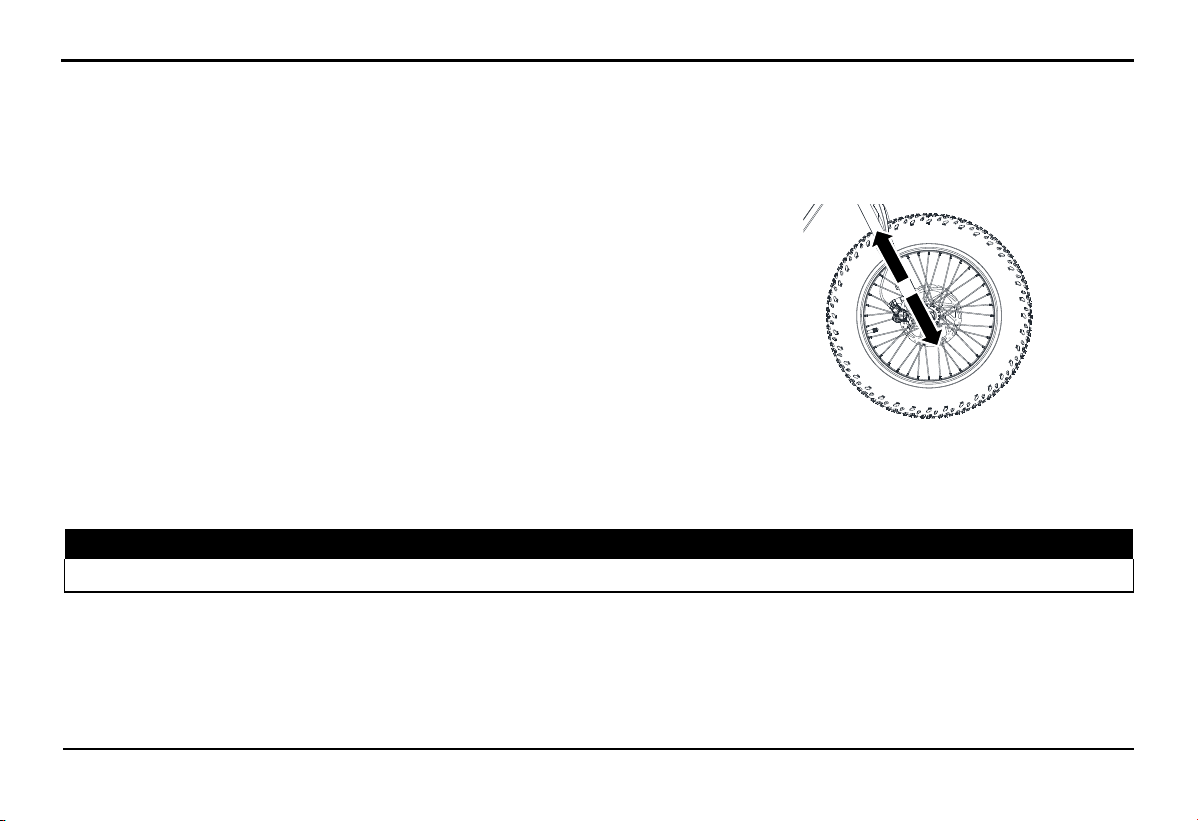
6.2.2.
Check and Lubricate the Left and Right Brake Levers
The operation of the brake lever (left/right) must be checked
before each ride, and the pivot pin (A) should be lubricated if
necessary.
Recommended lubricant: Grease
6.2. Basic Maintenance Principles
A
PERIODIC MAINTENANCE AND ADJUSTMENTS
45
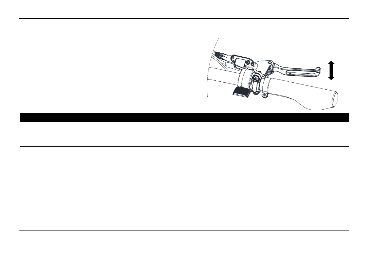
6.2.3.
Checking Brake Lever Wear
Applies to both left and right brake levers. When squeezing the
brakes, there should not be any free play at the end of the brake
lever. If this occurs, please contact the Distributors and Service
workshops of VinFast for a brake system inspection.
⚠ WARNING!
An unusual soft feeling when squeezing the brake is a sign of air entering the brake fluid. In this case, you must bring the
vehicle to
the Distributors and Service workshops of VinFast for inspection and bleeding of the brake system before use. Air in the brake flu
id
reduces brake performance and can lead to loss of control and accidents.
6.2.4.
Brake Light Switch
The brake light is usually activated when the brake is applied, so it should illuminate before the brake takes effect. If the brake light
does not come on when the brake is applied, you should bring it to the Distributors and Service workshops of VinFast.
6.2.5.
Lights/Bells/Switches/HMI Screen
Check the basic functionality of the lighting system, bells, switches, and HMI according to the maintenance schedule.
6.2.6.
Front Shock Absorber Check
The operation status of the front shock absorber should be regularly inspected as specified in the periodic maintenance schedule.
PERIODIC MAINTENANCE AND ADJUSTMENTS
46
Status Check:
Inspect the shock absorber tube surface for any damage or oil leakage.
Check the air pressure to see if it meets the standard and add air if necessary.
Operation Check:
Park the bike on a flat surface and keep it upright. Ensure that the bike is
securely held to prevent any danger of it tipping over.
While squeezing the front brake, bounce the front suspension up and down a
few times to check if the shock absorber operates and rebounds to the desired
setting. If not, proceed to readjust the shock absorber.
NOTE: If you detect any damage or any abnormal operation of the front shock absorber, please visit the Distributors and Service
workshops of VinFast to check.
6.2.7.
Front and rear wheel axle
⚠ WARNING!
Securely hold it to prevent the risk of the bike falling over.
Check the standard tightening force:
-
Front axle bolt: 28 - 35 Nm.
-
Rear axle bolt: 35 - 50 Nm.
PERIODIC MAINTENANCE AND ADJUSTMENTS
47
6.2.8.
Tire
Tire and tire pressure
Tires are the only contact point between the vehicle and the road surface. Safety in all driving conditions depends on the contact area
with the road. Therefore, special attention to tire condition is necessary when needed.
The appropriate tire inflation pressure must be within the manufacturer's standards, refer to the technical specifications table for
guidance
⚠ WARNING!
Operating the vehicle with tires that do not meet the standard can pose a safety risk to the user due to loss of control.
Do not operate the vehicle with an excessive load capacity. Controlling an overloaded vehicle can lead to safety issues and affect
the vehicle's quality.
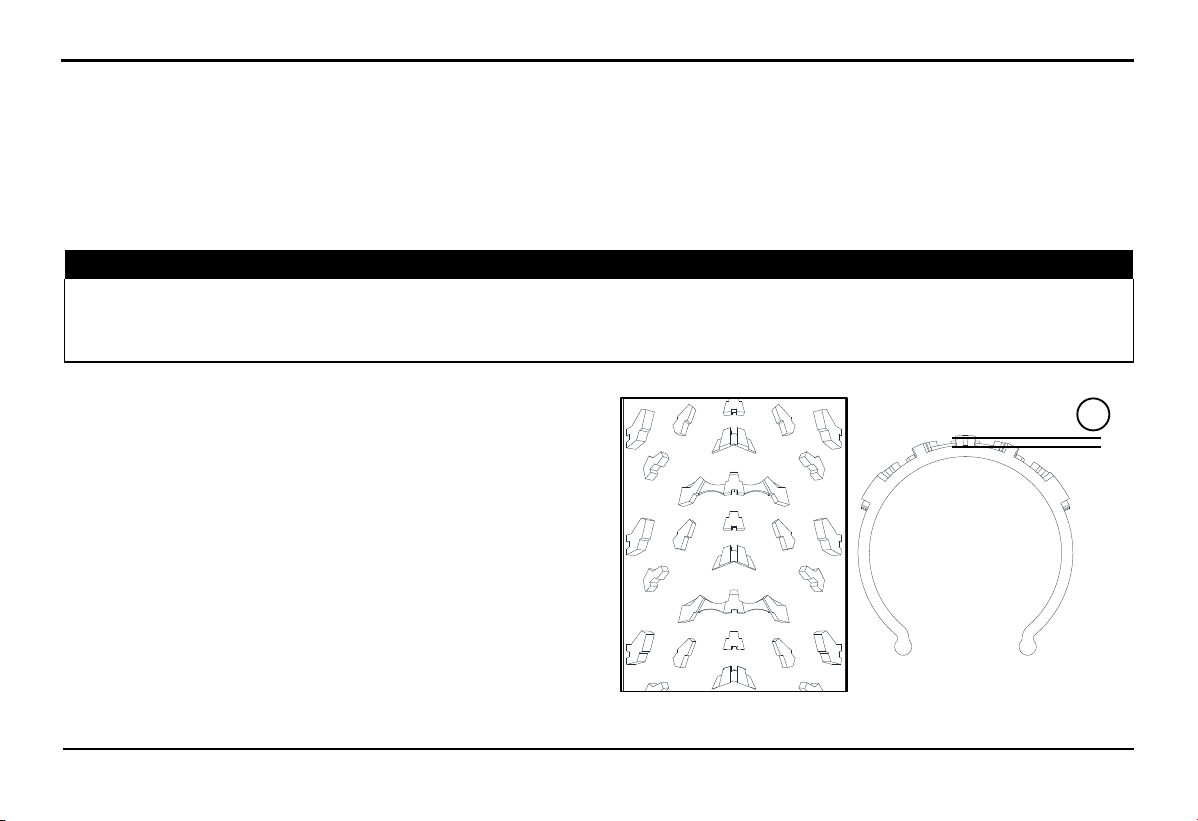
Tires check
It is advisable to thoroughly check the tires before each
operation:
Check tire wear by measuring the tire tread depth. Verify if the
tire tread depth (height A) is still within the recommended
limits. If the tires are worn out, replace them with new ones to
ensure safety.
If any nails or sharp objects puncture the tires, visit the
Distributors and Service workshops of VinFast to replace the
tires immediately.
A

PERIODIC MAINTENANCE AND ADJUSTMENTS
48
⚠ WARNING!
Please visit the Distributors and Service workshops of VinFast to replace tires that are excessively worn. Using tires that are
excessively worn can reduce the stability of the bike and may lead to loss of control.
The replacement of the entire wheel and related brake components should be done by the Distributors and Service workshops of
VinFast because we have the expertise and experience to perform this task.
Drive at a moderate speed after tire replacement, as the tire surface needs to "adapt" to the road surface in order to maximize its
optimal performance.
Tires information
This vehicle is equipped with tires that have inner tube and tire valves.
Tires can age even when they are not in use or are lightly used. Signs of aging may include cracks in the tire tread and sidewall,
sometimes accompanied by deformations in the tire structure. The condition of older and aging tires will be inspected by experts to
determine whether they are still suitable for future use or not.
6.2.9.
Rims check
To maximize the performance, durability, and safety of your bike, pay attention to the following points related to wheel rims.
Wheel rims should be inspected before each operation to check for cracks or deformation. If any damage is detected, bring the
vehicle to the Distributors and Service workshops of Vinfast to replace the rims. Do not attempt any repairs on wheel rims. It's
advisable to replace rims that are cracked or deformed.
Rim runout can affect maneuverability, reduce operational performance, and shorten tire lifespan. Therefore, wheel rims should be
properly aligned after each tire replacement, spokes replacement, or when new rims are installed
PERIODIC MAINTENANCE AND
ADJUSTMENTS
49
6.2.10.
Spokes check
Loose spokes:
+ Signs: The wheel is more wobbly than usual.
+ Inspection method: Check by rotating the wheel and observing the runout (when spokes are loose, the wheel's runout radial will
increase) or use a spoke tension gauge.
+ Solution: Bring the vehicle to the Distributors and Service workshops of VinFast to tighten the loose spokes and check the rim
runout.
Broken or cracked spokes at the hub:
+ Signs: The wheel may face runout when the spoke tip is broken.
+ Inspection method: Observe the appearance at the hub-end of the spoke.
+ Solution: Bring the vehicle to Distributors and Service workshops of VinFast for spoke replacement
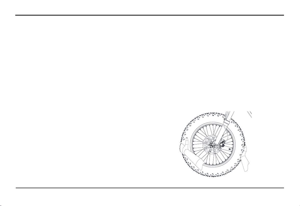
6.2.11.
Check the wheel bearings
The front and rear wheel bearings must be checked regularly
according to the maintenance schedule and lubricated as
required. If you notice loose or rough hub, or if the wheels do
not spin smoothly, please bring the vehicle to Distributors and
Service workshops of VinFast for bearing inspection
PERIODIC MAINTENANCE AND ADJUSTMENTS
50
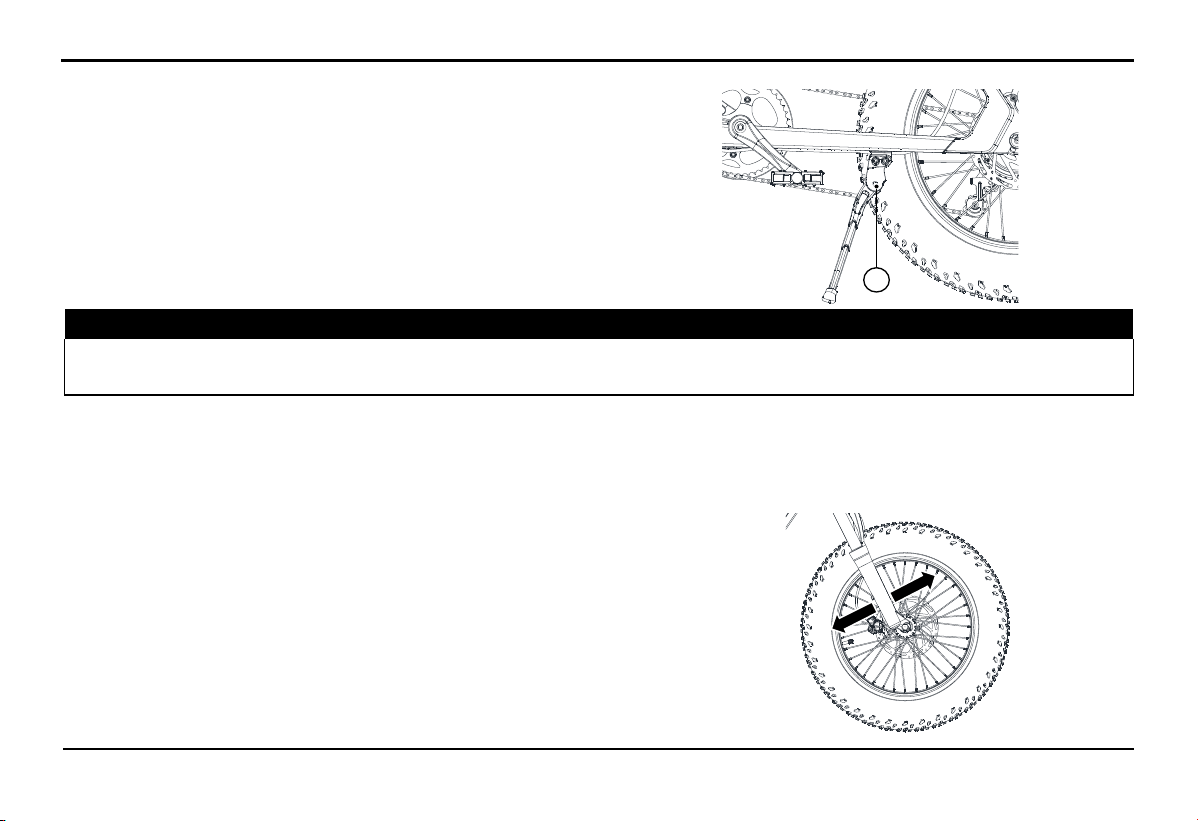
6.2.12.
Check and lubricate the side stand
The operation of the side stand must be checked every time you
operate the bike. The pivot points (A) and contact surfaces
should be lubricated if necessary.
⚠ WARNING!
If the side stand does not fold up or down smoothly, please bring the vehicle to the Distributors and Service workshops of VinFast
for inspection and repair. If the side stand does not fold up while driving, it can lead to a loss of control and accidents.
Recommended lubricant: Grease
6.2.13.
Headset cup check
If the bearing set or headset cup is worn or loose, it can be dangerous. Therefore, the operation of the headset cup must be checked
regularly according to the maintenance schedule and lubricated as prescribed.
Inspection procedure:
+ Securely place the bike using specialized equipment. Make sure to
keep the bike secure to prevent any dangers from the bike falling over.
+ Use both hands to grip the lower end of the suspension fork, and rock
it back and forth. If you feel any looseness, take the vehicle to the
Distributors and Service workshops of VinFast for inspection and repair.
A

PERIODIC MAINTENANCE AND
ADJUSTMENTS
51
Service and Maintenance Schedule for Front shock adsorber
Contents Each ride Every 50
Hours
Every 100
Hours
Check sag and fork extension, reset air pressure in both chambers. Every 5
Rides
Cleasn and inspect fork exterior, including travel indicating o-ring. Clean with mild
soap water.
x
Inspect stanchions for scratches, dents or other demage. x
Inspect and clean air valve threads to prevent dirt from entering air spring during
inflation.
x
Inspect headset preload, brake caliper connection torque and axle tension. Every 5
Rides
Remove lowers, clean and inspect bushings and seals, change oil bath. x
Full fork air spring and damper rebuild performed by VinFast’s Distributors and
Service workshops.
x
6.2.14.
Lithium-ion Battery
During the use of the bike, driving on rough road conditions can impact the Lithium-ion battery and the condition of the Lithium-ion
battery connections may change. Therefore, the Lithium-ion battery needs to be periodically inspected for external condition and the
assembly condition of the Lithium-ion battery connections.
6.2.15.
Chainring
The chain must be regularly inspected and lubricated. Inspect the chain more frequently when driving on rough roads, driving at high
speeds, or during continuous acceleration.
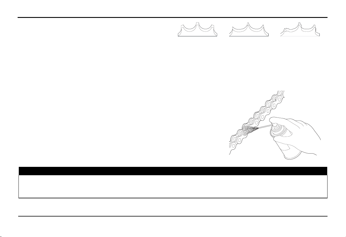
PERIODIC MAINTENANCE AND ADJUSTMENTS
52
If the load chain does not move smoothly, makes noise, has
damaged rollers, loose connecting links, or chain eyes, please
bring it to the Distributors and Service workshops of VinFast
for inspection. Also, check the chainring and rear cog of the
bike. If either is worn or has damaged teeth, bring it to
VinFast’s Distributors and Service workshops for
replacement.
Normal
(Good)
Worm out
(Replace)
Demaged
(Replace)
Illustration of Sprocket Damage
NOTE: Operating a new chain with a worn sprocket may cause accelerated wear of the chain.
Cleaning and Lubricating the Chain
Clean the chain and chainring simultaneously while turning the rear wheel.
Use a dry cloth with a high flash point solvent for cleaning. Use a soft-bristle
brush to clean the chain if it's dirty. After cleaning, wipe it dry and lubricate it
with recommended lubricating oil.
Recommended lubricating oil:
Chain lubricating oil. If chain lubricating oil is not available, use SAE 80 or SAE
90 oil.
⚠ WARNING!
Do not use gasoline or solvents with a low flash point to clean the chain. Doing so may lead to explosions. Avoid letting
lubricating oil adhere to the brakes or tires. Avoid applying too much lubricating oil to the chain to prevent it from splattering onto
clothing and the bikes
53
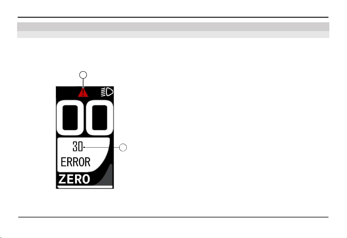
7.1. The HMI screen displays an error icon
7. Troubleshooting
TROUBLESHOOTING
Check the error codes displayed on the HMI instrument cluster.
Use a mobile app to read the error codes and receive instructions.
It is recommended to bring the vehicle to the authorized Distributors and Service workshops of VinFast for resolution.
If the self-diagnosis system detects an error, the error warning
symbol (A) will be displayed on the HMI screen.
The error code will be displayed at position (B). Please refer to the
error code table below.
A
B

54
TROUBLESHOOTING
Error code list
Error code Description Error code Description
01 Abnormal phase current 31 Reference voltage error
02 Abnormal bus current 36 Torque voltage error
03 HALL error 37 Speed sensor error
04 Brake or throttle error 38 Temperature error
05 Controller temperature error 40 Current feedback error
06 Motor temperature error 41 Drive voltage error
08 Controller communication error 42 Abnormal current
09 Low or high voltage 43 Motor phase error
20 WALK button and power button error 50 Torque voltage detect circuit error
30 Communication error 60 Display MCU error, reference voltage error
7.2.
Turn the throttle and the bike won't run
Check the error code displayed on the HMI.
Ensure that the charger has been disconnected from the vehicle.
7.3.
Unable to Start the Bike
Turn on the bike, but no response:
Turn off and then turn on the battery switch, then try starting again. If unsuccessful, please contact technical support.

55
8.1. Vehicle Care
8. Vehicle Care and Preservation
VEHICLE CARE AND PRESERVATION
Regularly clean and polish the bike to maintain its longevity. A clean vehicle is more likely to reveal any mechanical issues easily.
Saltwater or road salt can increase the likelihood of rust on the bike. Therefore, always remember to clean the bike thoroughly after
traveling on roads near the sea or with road salt.
8.2. Bike Wash
Please allow the motor, motor controller, brakes, lithium-ion battery, and high-temperature components to cool completely before
washing the bike.
1.
Remove mud and dirt from the bike using a pressure washer with appropriate pressure.
2.
If necessary, use a sponge or soft cloth soaked in a mild cleaning solution to wipe the bike.
Clean the headlights and plastic components carefully to avoid scratching them.
Avoid direct water spray on electrical system components.
3.
Rinse the bike thoroughly with plenty of water and use a soft cloth to dry it.
4.
After the bike is dry, lubricate the moving parts on the bike.
Ensure that lubricating oil does not adhere to the brakes or tires. Brake discs and brake pads contaminated with lubricating oil will
significantly reduce braking efficiency and may lead to accidents.
5.
Apply a rust prevention oil layer to protect the bike from rust.
Do not use rust prevention oil containing chemicals or strong cleaning agents, as they may damage metal and plastic components on
the bike. Avoid allowing rust prevention oil to splash onto the tires and brakes.

56
VEHICLE CARE AND PRESERVATION
If there are matte-painted details on the bike, avoid letting the rust-preventive oil adhere to those details.
NOTICE:
Do not spray directly into areas with rubber gaskets, such as motor shaft seals and front wheel shafts.
Do not use high-pressure water hoses to wash the bike
Dry the brakes after washing the bike.
Do not spray water directly under the saddle.
Do not spray water directly around the front lights, rear lights, HMI screen, throttle, and battery lock.
Do not apply rust-preventive oil or polishing oil to matte-painted surfaces.
Turn off the battery before washing the bike.
SPECIFICATIONS
57
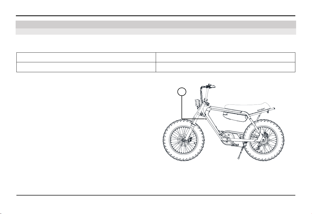
Please make a careful note of and store the important vehicle identification numbers. These codes are particularly useful when you
need to order spare parts from the Distributors and Service workshops of VinFast or in cases of vehicle theft.
FRAME NUMBER
MOTOR NUMBER
9.1.1.
Frame number
The frame number is engraved onto the vehicle
frame at position (A) as shown in the picture.
A
9.1. Vehicle Identification Number
9. Specifications

SPECIFICATIONS
58
Frame number consists of 17 characters.
R P X E 1 L H B %
# E * * * * * *
Definition:
RPX Vehicle manufacturer and assembler code.
RPX = Vinfast Trading and Production Joint Stock Company
E1 Bike type number.
E1 = E-BIKE
L Battery type code.
L = Lithium-ion battery
H Engine type code.
H = The engine is located in the rear wheel
B
Vehicle group code.
B = Electric bike
% Vehicle market code.
V = Viet Nam E = Europe A = America
# Frame manufacture year code.
P = 2023 R = 2024 S = 2025 T = 2026 V = 2027
E The electric bike factory code of Vinfast Trading and Production Joint Stock Company.
****** Frame production serial number.
SPECIFICATIONS
59
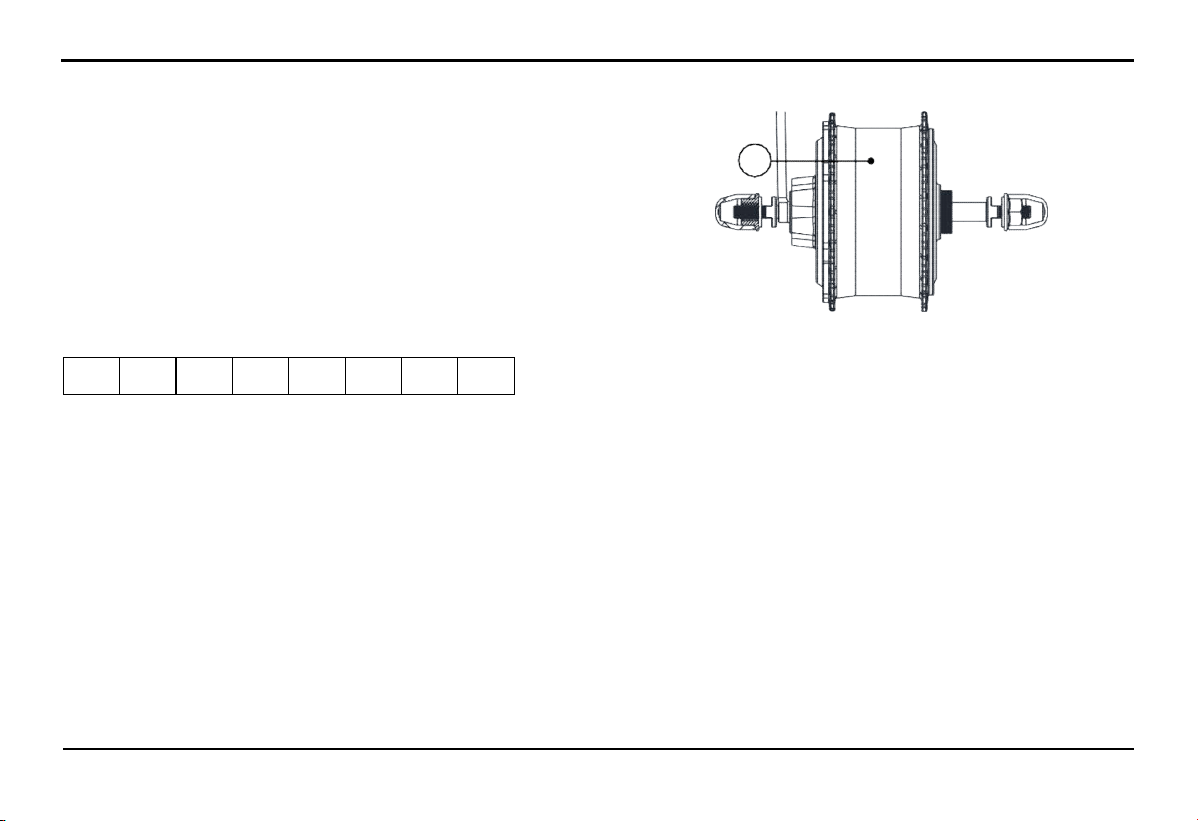
9.1.2.
Motor number
The motor number (B) is etched onto the engine block
The motor number consists of the last 8 digits in the numerical sequence.
2 2 4 3 0 0 0 1
Definition:
22: Year of manufacture.
43: Week of manufacture.
0001: Motor serial number.
B
M150-48V75W20''22430001

SPECIFICATIONS
60
9.2. Specifications
MOTOR
Motor type Brushless direct current motor
Maximum speed 25 km/h (EU Market)
32 km/h (US Market)
LITHIUM-ION BATTERY SYSTEM
Battery type Lithium-ion
Nominal capacity 13.6 Ah
Average weight 3.2 ± 0.2 kg
Nominal voltage 47.2 V
Standard charging time
(Charging time varies depending on the battery's condition, such
as starting voltage and level of discharge)
5.3 hour
TRANSMISSION
Power transmission Chain drive
SHOCK ABSORBER/BRAKE SYSTEM
Front shock absorber Air shock absorber
Rear shock absorber Not available
Front brakes Disc
Rear brakes Disc
BASIC SIZE
Length x Width x Height 1730 x 720 x 1056 mm

SPECIFICATIONS
61
Front-rear wheelbase 1143 mm
Seat height 795 mm
Ground clearance 180 mm
Maximum steering angle left/right 60º/60º
WEIGHT
Curb weight (vehicle and battery) 31.4 kg
Front axle load distribution 12.65 kg
Rear axle load distribution 18.75 kg
Permissible load (including driver and accompanying weigh) 130 kg
Number of permitted passengers 01 person
Total weight 161.4 kg
WHEEL
Front wheel (size, load, speed, pressure) 90/100-16; 24B; 140 kPa
Rear wheel (size, load, speed, pressure) 90/100-16; 24B; 140 kPa

NOTE
62


Dinh Vu - Cat Hai Economic Zone, Cat Hai Island, Cat Hai Town, Cat
Hai District, Hai Phong City, Vietnam
VINFAST TRADING AND PRODUCTION JOINT STOCK COMPANY
Boundless Together