Before the rst use of this heater, please read this USER’S MANUAL
very carefully. This USER’S MANUAL has been designed to instruct
you as to the proper manner in which to assemble, maintain, store,
and most importantly, how to operate the heater in a safe and efcient
manner. Please keep this manual for future reference.
CONSUMER: Retain this manual for future reference.
Questions, problems, missing parts? Before returning to your retailer, call our customer
service department at 877-447-4768 8:00 a.m. - 4:30 pm CST, Monday - Friday.
or email us at [email protected]
IMEG10000WB-PIB
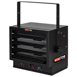
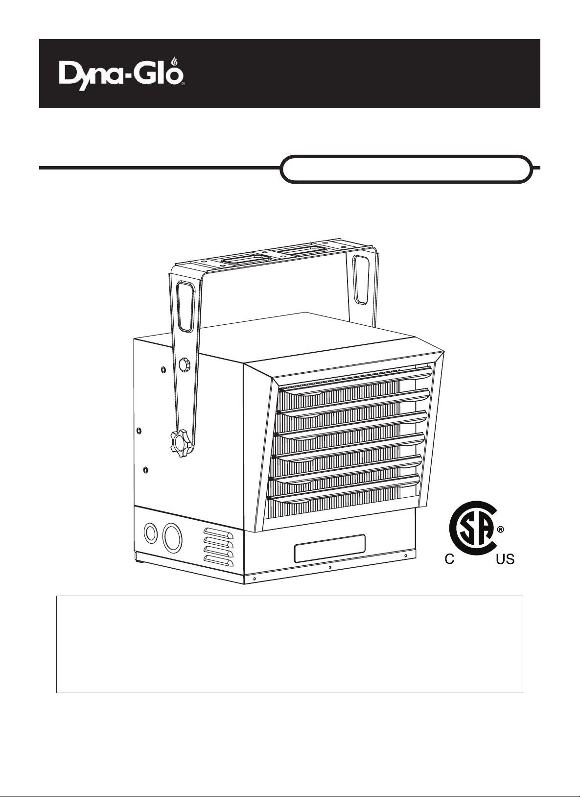
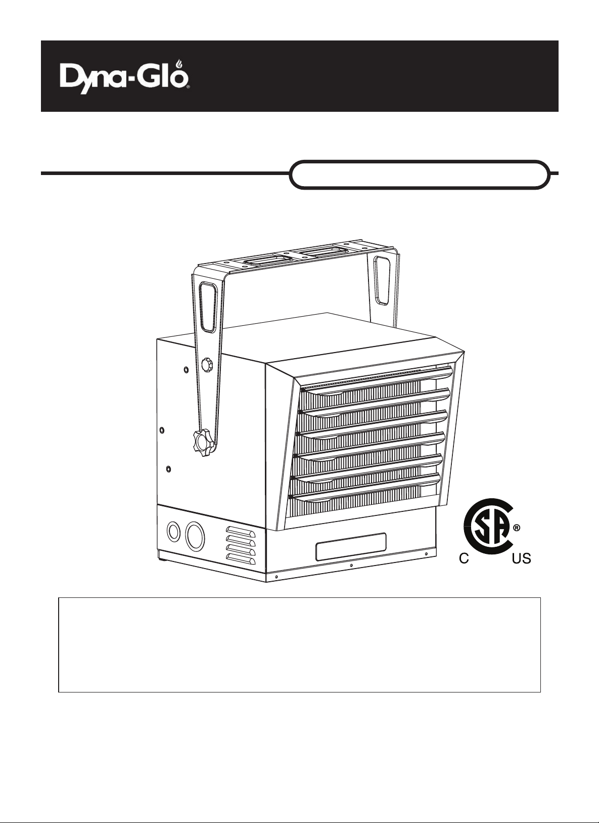
Electric Garage Heater
INSTALLATION & MAINTENANCE INSTRUCTIONS
10,000W / 240V / 34,120 BTU
EG10000WB
CSA C22.2 No. 46-13
UL 2021

IMPORTANT INSTRUCTIONS
SAVE THESE INSTRUCTIONS
2
PET OWNERS WARNING: The health of some small pets including birds are extremely
sensitive to the fumes produced during the rst-time use of many appliances. These fumes are
not harmful to humans but we recommended that you do not use your heater around birds and
small pets during its initial use until the manufacturing protective coatings burn off.
THIS HEATER REQUIRES HARDWIRE INSTALLATION (NO PLUG). THE
INSTALLATION OF THIS PRODUCT MUST BE CARRIED OUT BY A CERTIFIED
ELECTRICIAN AND IN ACCORDANCE WITH ALL LOCAL AND NATIONAL
ELECTRICAL CODES.
When using electrical appliances, basic precautions should always be followed to reduce the
risk of re, electric shock, and injury to persons, including the following:
1. Read all instructions before installing or using this heater.
2. This heater is hot when in use. To avoid burns, do not let bare skin touch hot
surfaces. Keep combustible materials, such as electrical cords, furniture, pillows,
bedding, papers, clothes, and curtains at least 3 feet (0.9 m) from the front of the
heater and keep them away from the sides and rear.
3. Extreme caution is necessary when any heater is used by or near children or
invalids and whenever the heater is left operating and unattended.
4. Always turn off the power to the heater when not in use.
5. Do not operate any heater after the heater malfunctions, has been dropped or
damaged in any manner. Disconnect power at the service panel and have the
heater inspected by a reputable electrician before reusing.
6. Do not use outdoors.
7. This heater is not intended for use in bathrooms, laundry areas and similar indoor
locations. Never locate heater where it may fall into a bathtub or other water
container.
8. Do not insert or allow foreign objects to enter any ventilation or exhaust opening as
this may cause an electric shock or re, or damage the heater.
9. To prevent a possible re, do not block air intakes or exhaust in any manner. Do not
use on soft surfaces, like a bed, where openings may become blocked.
10. A heater has hot and arcing or sparking parts inside. Do not use it in areas where
gasoline, paint, or ammable liquids are used or stored.
11. Use this heater only as described in this manual. Any other use not recommended
by the manufacturer may cause re, electric shock, or injury to persons.
12. To disconnect heater, turn controls to off, and turn off power to heater circuit at main
disconnect panel.
13. If the red alarm light on the front of the unit illuminates, immediately turn the heater
off and inspect for any objects on or adjacent to the heater that may have blocked
the airow or otherwise caused high temperaturs to have occurred. DO NOT
OPERATE THE HEATER WITH THE ALARM LIGHT ILLUMINATING.
This Product can expose you to chemicals including Diisononyl phthalate (DINP) which is known
to the State of California to cause cancer and Di-isodecyl phthalates (DIDP) which is known to the
State of California to cause birth defects or other reproductive harm.
For more information go to www.p65Warnings.ca.gov
WARNING

3
FCC COMPLIANCE
PLEASE NOTE THAT CHANGES OR MODIFICATIONS OF THIS PRODUCT IS NOT
EXPRESSLY APPROVED BY THE PARTY RESPONSIBLE FOR COMPLIANCE COULD VOID
THE USER’S AUTHORITY TO OPERATE THE EQUIPMENT.
NOTE: This equipment has been tested and found to comply with the limits for a Class B digital
device, pursuant to Part 15 of the FCC Rules. These limits are designed to provide reasonable
protection against harmful interference in a residential installation. This equipment generates,
uses and can radiate radio frequency energy and, if not installed and used in accordance with
the instructions, may cause harmful interference to radio communications. However, there is no
guarantee that interference will not occur in a particular installation.
1. If this equipment does cause harmful interference to radio or television reception, which
can be determined by turning the equipment off and on, the user is encouraged to try to
correct the interference by one or more of the following measures:
2. Reorient or relocate the receiving antenna.
3. Increase the separation between the equipment and receiver.
4. Connect the equipment into an outlet on a circuit different from that to which the receiver is
connected.
5. Consult the dealer or an experienced radio/TV technician for help.
This device complies with Part 15 of the FCC Rules. Operation is subject to the following two
conditions: (1) this device may not cause harmful interference, and (2) this device must accept any
interference received, including interference that may cause undesired operation.
1. Importer: GHP Group, Inc.
2. Address: 6440 W Howard St. Niles IL, 60714
3. Telephone number: (847) 324 - 5900
FCC ID: 2ANDL-WBR1-IPEX
44
ITEM PAGE #
SPECIFICATIONS ........................................................................... 4
SAFETY INFORMATION ................................................................. 5
LOCATING HEATER ....................................................................... 5
PRE-INSTALLATION ....................................................................... 6
INSTALLATION ............................................................................... 7
OPERATING INSTRUCTIONS ........................................................ 11
MAINTENANCE .............................................................................. 15
REPLACEMENT PARTS ................................................................. 15
TROUBLESHOOTING .................................................................... 16
1. Use only copper wires rated for at least 60ºC.
2. Heater air ow must be directed parallel to or away from adjacent wall.
3. Observe all wall, oor and ceiling clearance requirements.
4. All wiring must be done according to national and local electrical codes. The
heater must be grounded as a precaution against possible electrical shock.
Heater circuit must be protected with proper fuses.
5. The mounting structure and the anchoring hardware must be capable of
supporting the weight of the heater and the mounting bracket (if used).
TABLE OF CONTENTS
SPECIFICATIONS
SAFETY INFORMATION
THIS HEATER REQUIRES HARDWIRE INSTALLATION (NO PLUG). THE INSTALLATION OF THIS
PRODUCT MUST BE CARRIED OUT BY A CERTIFIED ELECTRICIAN AND IN ACCORDANCE WITH
ALL LOCAL AND NATIONAL ELECTRICAL CODES.
NOTE: COMPATIBLE WITH SOME 240V LINE VOLTAGE DOUBLE POLE WALL THERMOSTATS.
MUST BE INSTALLED BY A CERTIFIED ELECTRICIAN.
READ AND UNDERSTAND ALL INSTALLATION & OPERATION INSTRUCTIONS PRIOR TO
OPERATING THIS UNIT. OBSERVE ALL SAFETY INSTRUCTIONS.
WARNING
ITEM PAGE #
SPECIFICATIONS ........................................................................... 4
SAFETY INFORMATION ................................................................. 4
LOCATING HEATER ....................................................................... 5
PRE-INSTALLATION ....................................................................... 6
INSTALLATION ............................................................................... 7
OPERATING INSTRUCTIONS ........................................................ 11
MAINTENANCE .............................................................................. 15
REPLACEMENT PARTS ................................................................. 15
TROUBLESHOOTING .................................................................... 16
Rating Switch Setting Volts Phase Hz AMPS BTU/hour
10000W II 240 1 60 41.7 34120
7500W I 240 1 60 31.3 25590
7500W II 208 1 60 36.1 25590
5600W I 208 1 60 26.9 19107
55
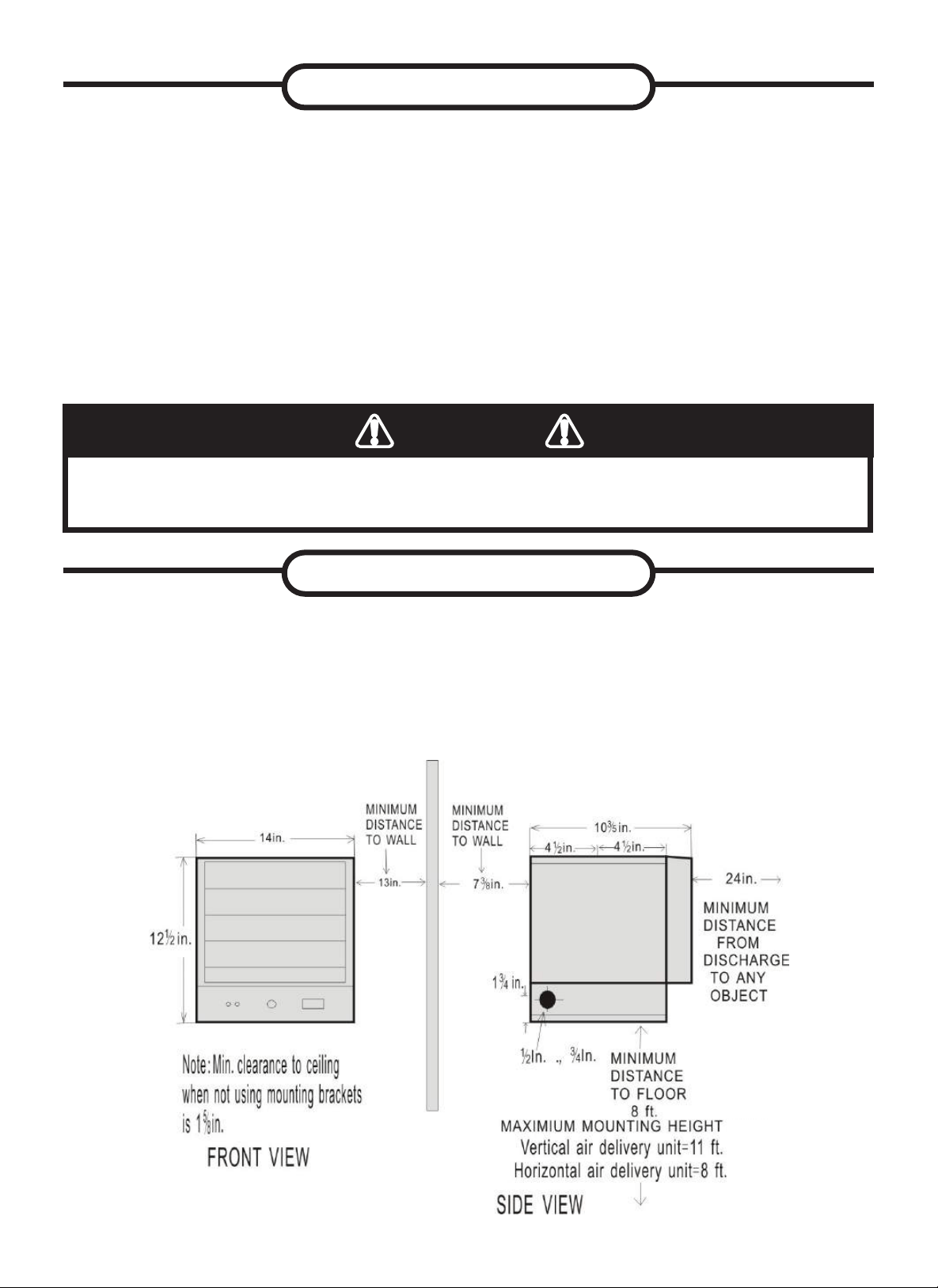
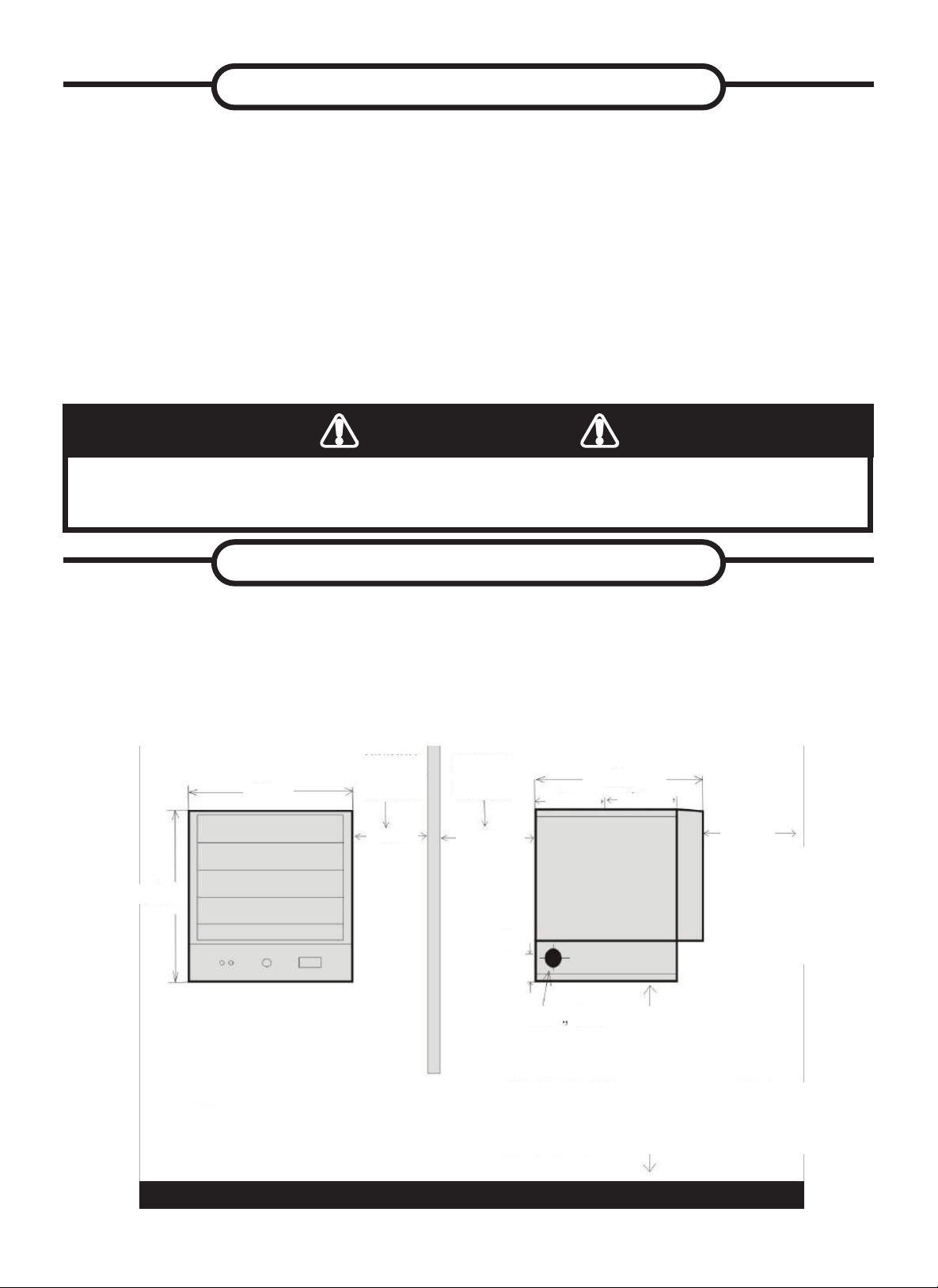
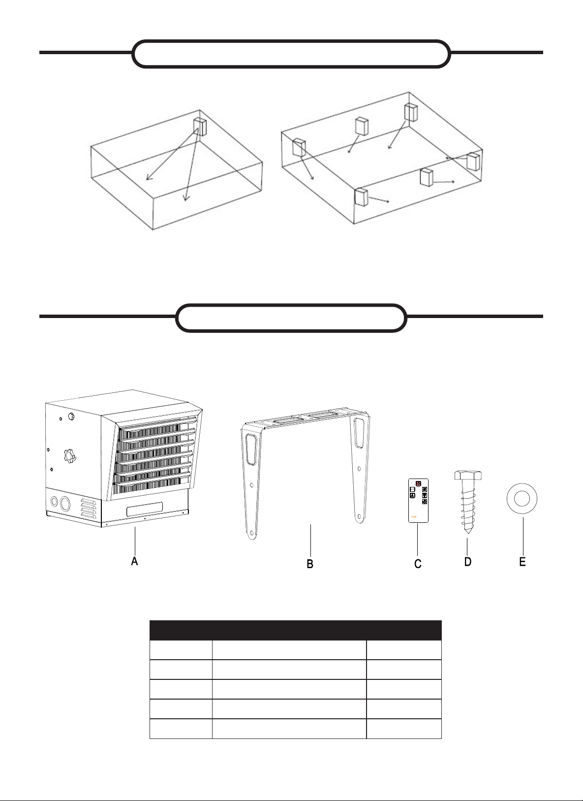
Install heater away from trafc areas, maintaining clearances stated in gure
2 (below). The air ow direction should not be restricted (ie. by columns or
machinery). The air ow should wipe exposed walls rather than blowing directly
on them. When more than one heater is used in an area, heaters should be
installed so that the air discharge of each heater supports the air ow of the
others, to provide best warm air circulation as shown in gure 3.
Figure 2
SAFETY INFORMATION
LOCATING HEATER
IMPROPER INSTALLATION OR FAILURE TO FOLLOW THE PROCEDURES OUTLINED IN THIS
INSTRUCTION MANUAL CAN RESULT IN SERIOUS ELECTRICAL SHOCK.
WARNING
6. All electrical power must be disconnected at the main service box, which
must be locked before connecting, inspecting, cleaning or servicing the
heater. This is an important precaution to prevent serious electric shock.
7. This is heater is not suitable for use in hazardous locations containing
explosive liquids or vapours. This heater has hot or arcing or sparking parts
inside. Do not use it in areas where gasoline, paint or ammable liquids are
used or stored.
8. This heater is not suitable for use in corrosive atmospheres such as marine
greenhouses or chemical storage areas.
9. This heater must be mounted at least 8 feet off the oor. For specic
clearances, see gure 2.
FOR:

66
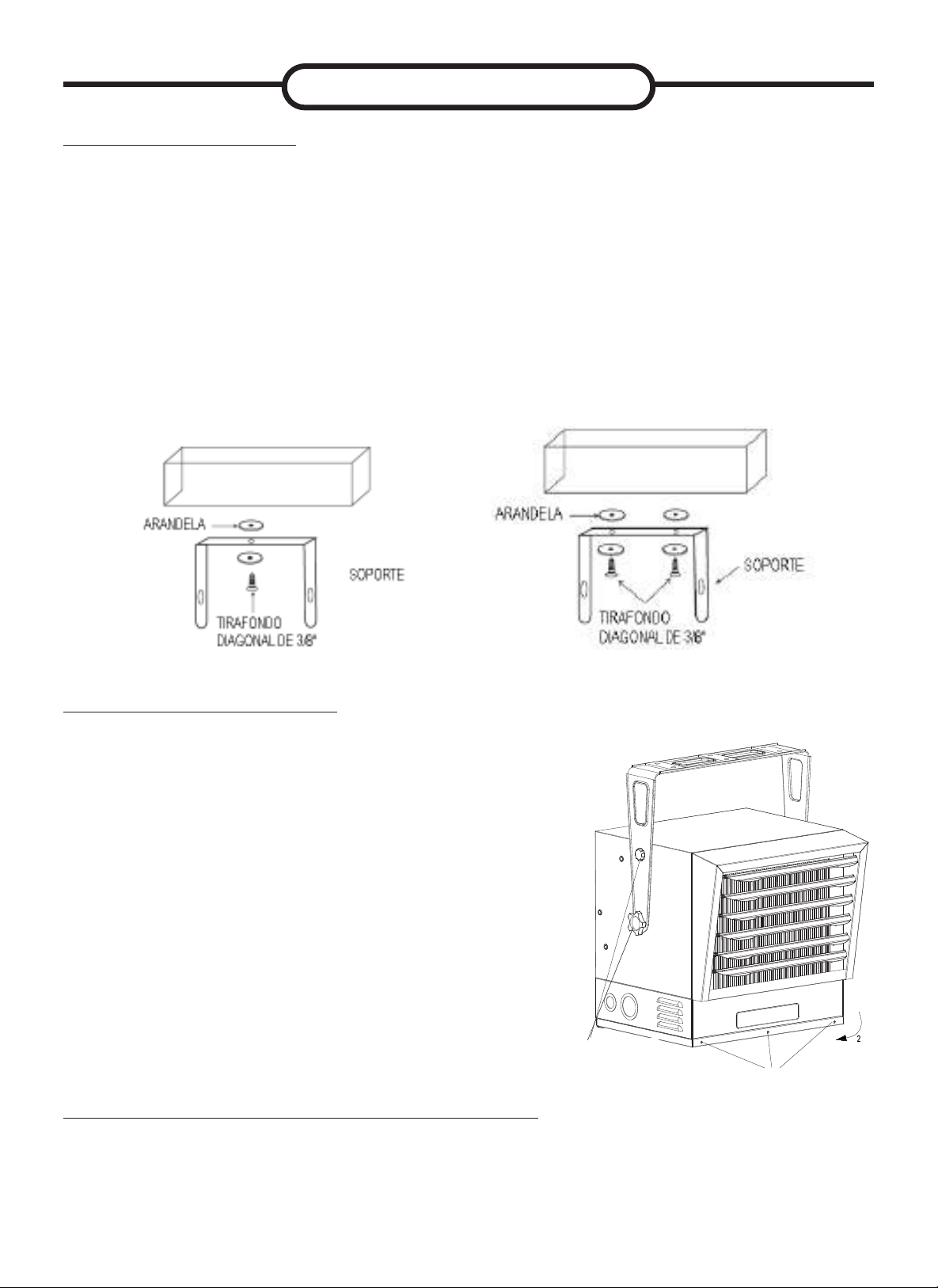
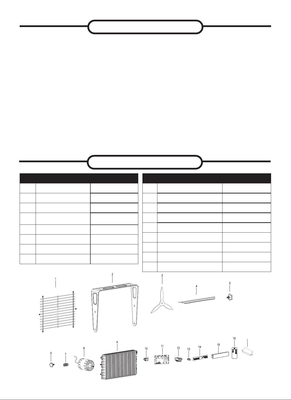
Part Description Quantity
A Garage Heater 1
B Mounting Bracket 1
C Infrared Remote Control 1
D Screw 6
E Washer 12
PRE-INSTALLATION
LOCATING HEATER
Figure 3
77
Wood Ceiling Wood Ceiling
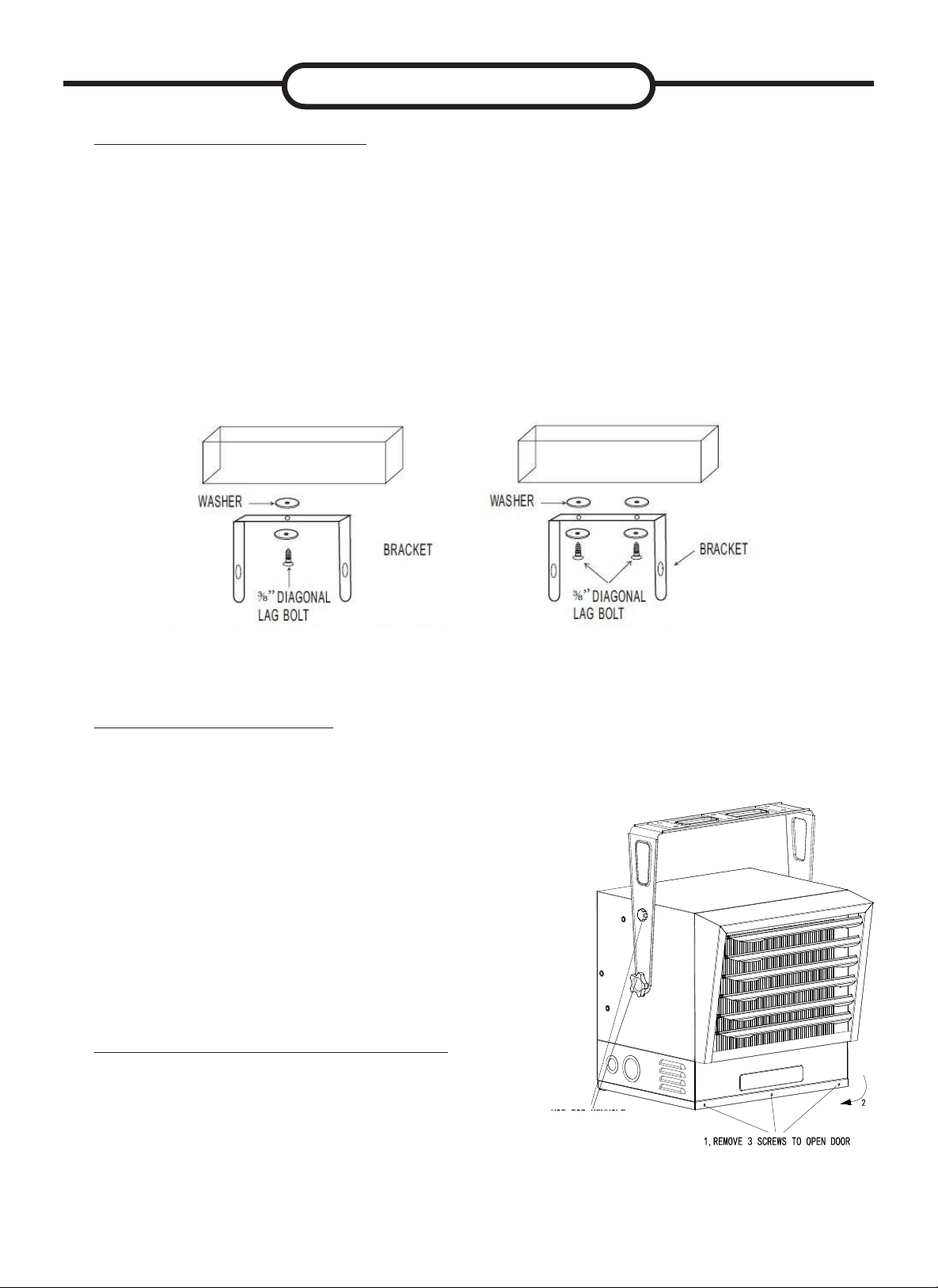
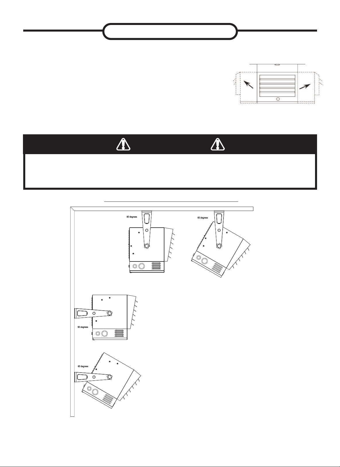
MOUNTING THE BRACKET
Refer to Figures 4a and 4b.
1. Locate a wood stud in the wood ceiling joist. If you cannot locate a wood
stud, you have to install a wood piece on the ceiling as this heater must be
securely fastened.
2. Remove the mounting bracket from the heating unit by loosening bracket
screws with a wrench and slipping the handle off over the screw heads.
3. Place a washer on screws before inserting through the holes in the mounting
bracket and screw them securely into a ceiling joist.
NOTE: If you want to swivel the heater either to the right or left adding a washer
to both sides of the bracket is recommended. A longer lag bolt may be required
to properly secure the unit. See Figure 4a.
HANGING THE HEATER
1. Attach the heating unit to the mounting bracket.
2. Lift the heater up and into the mounting
bracket.
3. Align the bracket screws with the keyhole slots
in the mounting bracket.
4. Tighten the bracket screws with a wrench so
the unit is securely suspended at horizontal or
vertical level.
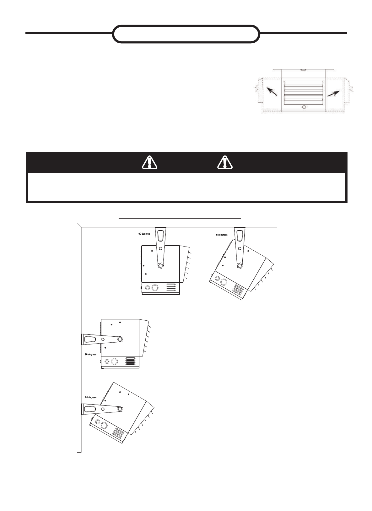
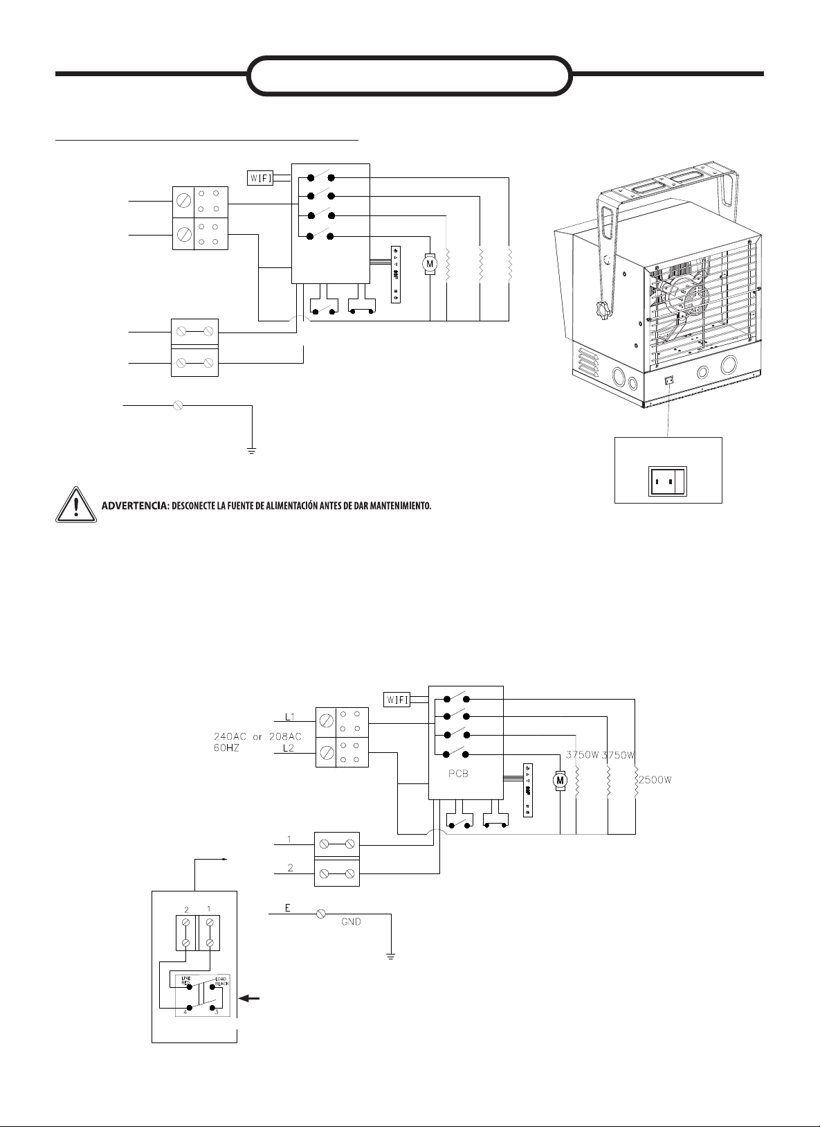
5. The heater can be mounted with different
angles listed in the drawing on page 7 as long
as you maintain proper clearance listed on
page 4.
Figure 5
ADJUSTING AIR FLOW DIRECTION
1. To turn the unit when it has been installed
with a single lag bolt (as shown in gure
4a), simply turn the entire heater as needed.
The unit cannot be turned horizontally if it
has been installed with 2 lag bolts.
2. To tilt the unit vertically, loosen the bracket
screws (see gure 5).
Figure 4a. Single-Screw Mounting Figure 4b. Double-Screw Mounting
INSTALLATION
LOOSEN KNOBS AND SELECT
MOUNTING HOLE BASED ON DE-
SIRED HEATER ANGLE.REFER
TO DIAGRAM ON PAGE 8.
88
MULTIPLE VERTICAL ANGLES
3. Adjust louvers to the desired position (see Figure 6).
NOTE: The louvers are designed so they cannot
be completely closed. Do not attempt to bypass this
feature; damage to the unit can result.
INSTALLATION
Figure 6
TO PREVENT POSSIBLE ELECTRIC SHOCK, DISCONNECT POWER TO THE HEATER AT THE
MAIN SERVICE BOX BEFORE ATTEMPTING TO ADJUST THE HEAT OUTPUT OF THIS UNIT.
WARNING
99
Selection Switch
(Heater’s thermostat, External thermostat)
Heater’s
thermostat
External
thermostat
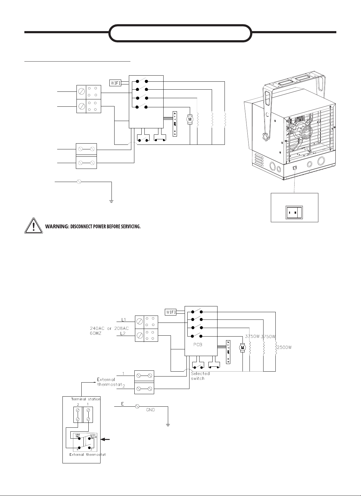
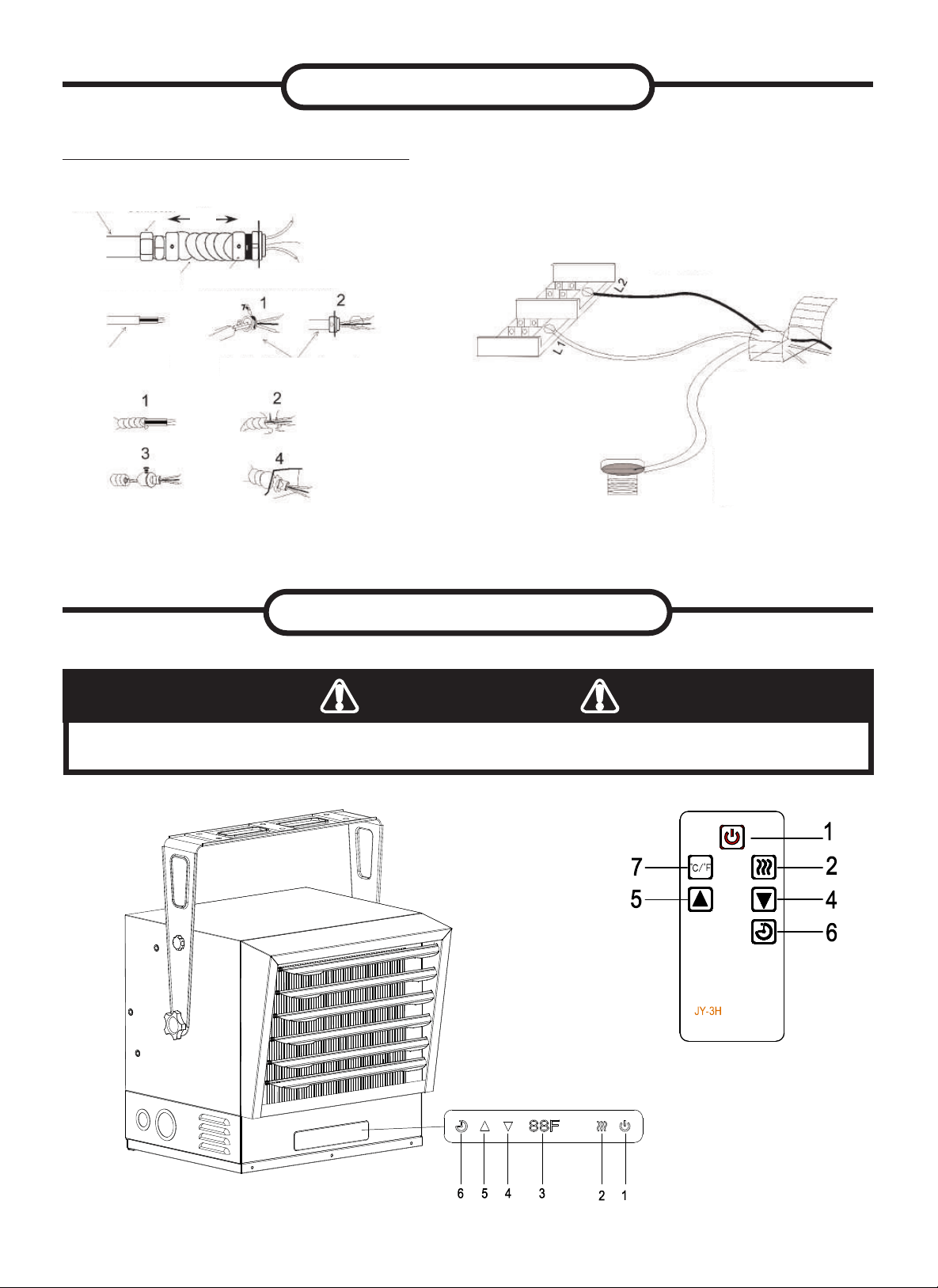
CONNECTING THE POWER
If you will use an external temperature control (external thermostat) to control
the heater to be operated or not, please follow below attention points:
1. Make sure that the heater's temperature control knob (thermostat knob) is turned
fully clockwise.
2. Connect the wire according to below wiring diagram.
INSTALLATION
GND
E
L1
L2
1
2
240AC or 208AC
60HZ
External
thermostat
PCB
Selected
switch
2500W
3750W
3750W
NOTE: When using to DGT-240
Thermostat, you must connect
“Load Black” to “3” on the
thermostat.
1010
3. Connect the wire to the power block located in the base of the heater - See
Figure 7.
4. Turn on the power at the main service.
NOTE: All wiring must be carried out by a Certied Electrician and must be in
accordance to national and local electrical codes. For certain applications, conduit
may be required, See Figure 7. Check local electrical codes. If you run the wiring in
conduit and wish to be able to turn the heater be sure to purchase enough exible
conduit to allow the heater to be turned.
INSTALLATION
HIGH TEMPERATURES – RISK OF FIRE. KEEP FLAMMABLE MATERIALS, SUCH AS
FURNITURE, PILLOWS, BEDDING, PAPERS, CLOTHES, ELECTRICAL CORDS AND CURTAINS
AT LEAST 3 FT. (0.9 M) FROM THE FRONT AND TOP OF THE HEATER AND KEEP THEM AWAY
FROM THE SIDES AND REAR. TO REDUCE THE RISK OF FIRE, DO NOT USE IT IN AREAS
WHERE GASOLINE, PAINT OR FLAMMABLE LIQUIDS ARE USED OR STORED.
WARNING
TO REDUCE THE RISK OF FIRE, DO NOT STORE OR USE GASOLINE OR OTHER
FLAMMABLE VAPORS AND LIQUIDS IN THE VICINITY OF THE HEATER.
WARNING
CONNECTING THE POWER
3. The external temperature control (external thermostat): a certied thermostat
must be used.
4. The lead wire of external temperature control (external thermostat) can not
be less than 14AWG.
1. Remove the screw from the front of the unit to connect the power to the heater.
2. Attach the cable connectors to the unit (See Figure 7). Select power supply
wire to comply with local and national electric codes using heater rating given
on the rating label.
COOLDOWN CYCLE
The cool down cycle may take up to 5 minutes and continue to turn on and off as
needed to properly cool down.
THIS APPLIANCE MUST BE GROUNDED!
THE APPLIANCE MUST CONNECT TO A CURRENT PROTECTION CIRCUIT OR DEVICE
BEFORE BEING CONNECTED TO POWER SUPPLY!
WARNING
TO PROTECT THE HEATING ELEMENT
When starting the heater, turning the temperature control clockwise slowly to terminal,
the unit starts the fan rst then starts the heating element.
When shutting off the heater, turning the temperature control counter-clockwise to off,
the heating element rst will turn off then the fan will run a short cooling cycle and then
turn off.
1111
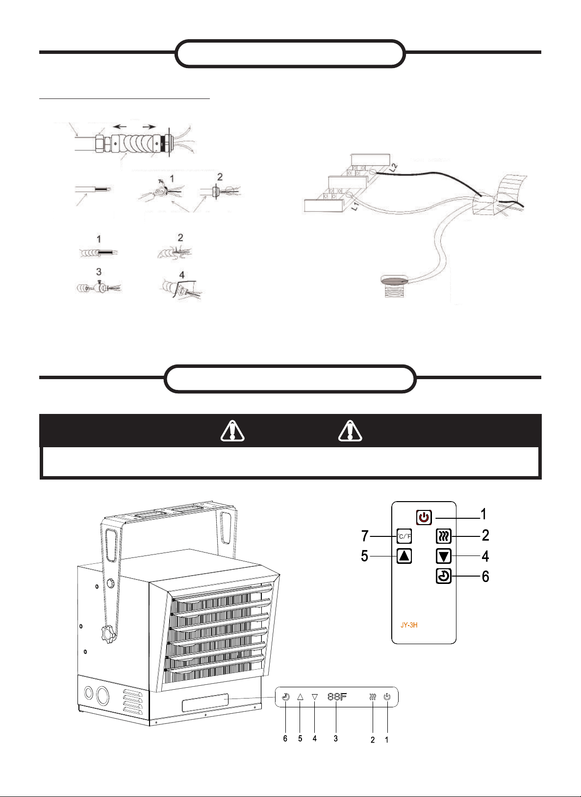
CONNECTING THE POWER
Connectors, cable, and hardware used to
wire the heater
Figure 7
Conduit
Connector
Conduit
Flexible Conduit
Flexible NM Cable
Flexible NM Cable Connector
Flexible Conduit Connector
WHITE
BLACK
GREEN
(or bare copper)
3ft
INSTALLATION
OPERATING INSTRUCTIONS
THE HEATER MUST BE PROPERLY INSTALLED BEFORE IT IS USED.
WARNING
Control Panel
1212
OPERATING INSTRUCTIONS
Check that the garage heaters outlet grill is not covered or obstructed in anyway, and make
sure the power to the unit is switched on.
The garage heater control functions can be accessed in three (3) ways:
• Using the touchpad control panel, located on the front of the garage heater below the air
guide plates.
• Using the multifunction remote control unit.
• Using the application on your mobile device
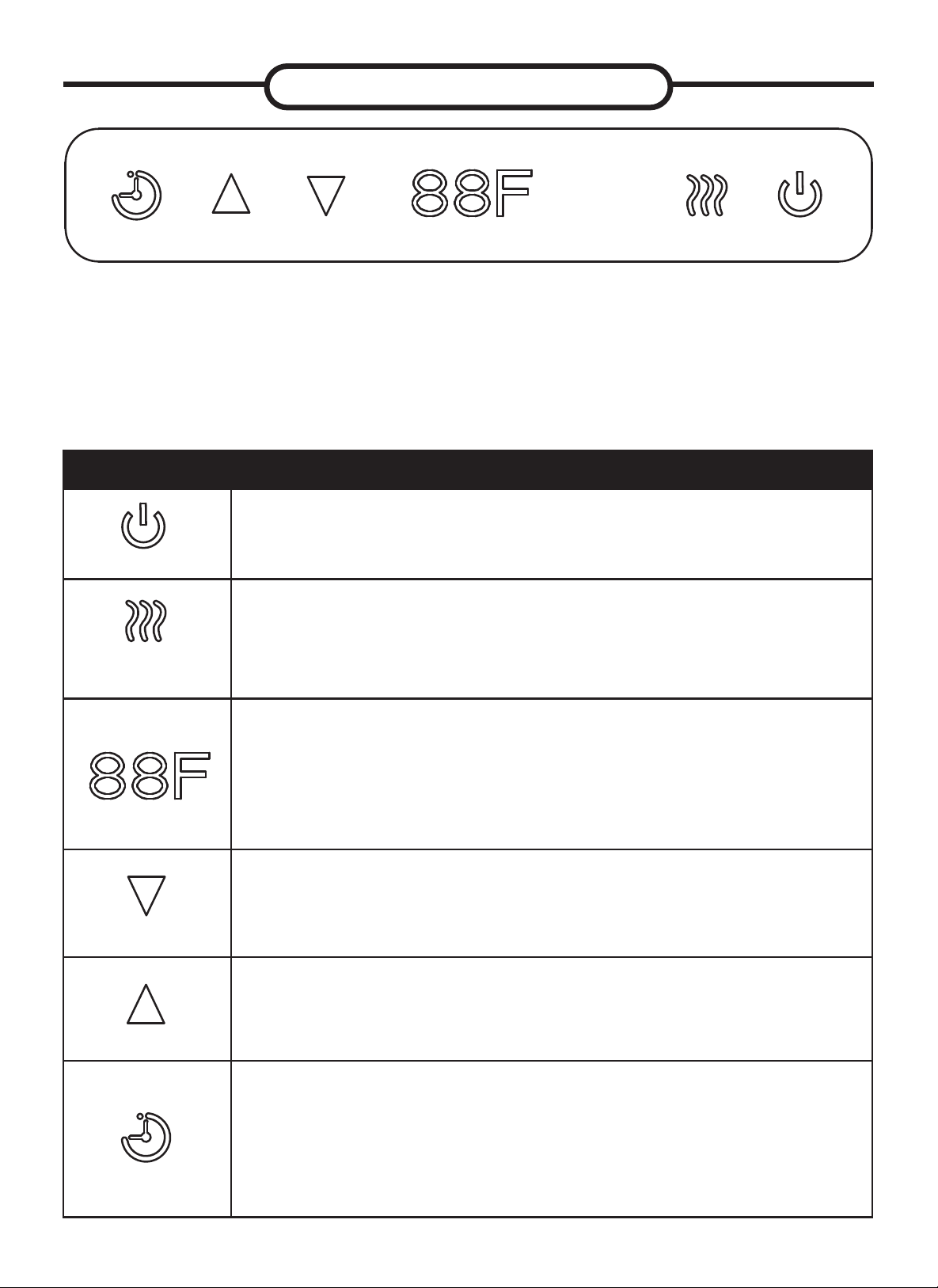
Icon What the heater will do:
Figure 1
Main Power Button:
This button supplies power to all of the garage heaters functions. It must
be turned on for the garage heater to work
Figure 2
Heater Control Button:
This button adjusts the 4 heating stages: AU, H, L, FA: AU (The heater
will adjust between Low (7500W displays “L”) and High (10000W
displays “H”) based on room temperature) ; H (high 10000W displays
“H”); L (Low 7500W displays “L”) ; FA (Fan Only).
Figure 3
Temperature/Timer Display:
This LED display shows the set point for the temperature and timer
functions. When either of these functions is activated, the display reects
the set point for ve seconds and then fades to black. Any change to he
set point of the temperature or timer will reactivate the display, which
again fades after ve seconds.
Figure 4
DOWN Control Button:
This button is used to decrease temperature or timer settiing. It adjusts
the temperature range between 10°C - 35°C (50°F - 95°F) in 1°F (/1°C)
increments.
Figure 5
UP Control Button:
This button is increasing temperature or timer setting. It adjusts the
temperature range between 10°C - 35°C (50°F - 95°F) in 1°F (/1°C)
increments.
Figure 6
Timer Button:
This button controls the Timer ON/OFF and 8 settings from 1hour to 8
hours. When the Timer is rst turned on, it will come on at the shortest
time setting (1hour). Each time the Timer button is pressed, the time
increases by 1 hour, up to the longest setting (8 hours). Once the set
time expires, all garage heaters functions will be automatically turn off.

13
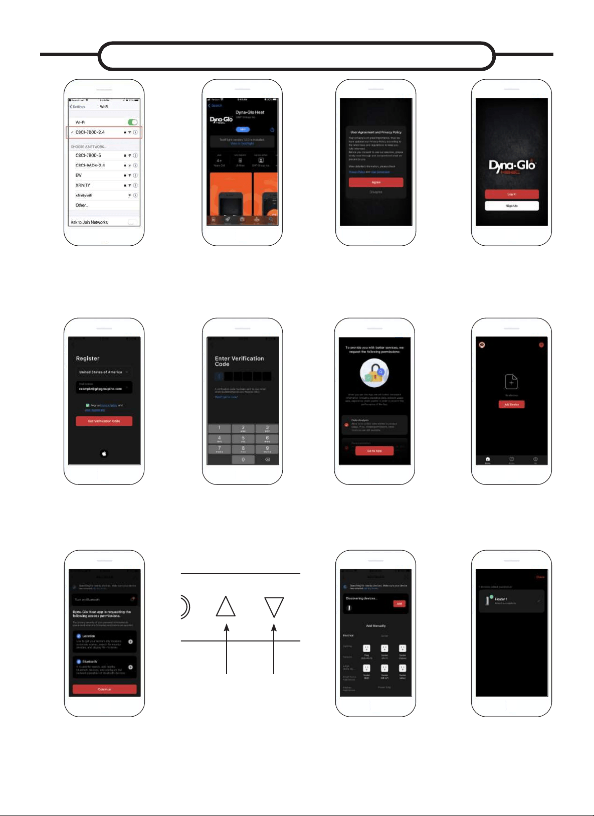
MOBILE APP OPERATING INSTRUCTIONS
Connect to your phone to a
2.4 GHz wi network.
*for some dual band routers, you may
need to manually create a network
dedicated to 2.4GHz.
While the heater is
plugged in and turned
on, press and hold the
up and down arrows
symbol on control
screen for 5 seconds.
You should hear a
beep after doing so.
Download the Dyna Glo
Heater App on Google Play
or on iOS App Store.
Click “Agree” On The User
Agreement and Privacy
Policy.
Allow Dyna-Glo to connect
to your local network and
provide data analysis and
personalization.
Create Dyna-Glo Account
or Login to existing account.
Click “Add Device” on the
home page.
To Create New Account:
Enter email address to and tap the box
below to agree to the Privacy Policy and
User Agreement. A verication code will
be sent to the provided email address.
Allow Dyna-Glo Heat to
access the device’s location
and bluetooth.
Enter in verication code.
After Step 7 a pop up will
appear on your phone that it
is searching for the device
to pair. Once this appears
click “Add”.
Your Screen should
look like this: If it shows
any error notications,
check out our wi trouble
shooting guide online.
4
6
Enjoy your new Heat
6WRUP:LÀ+HDWHU
If you have any ques-
tions or concerns, feel
free to contact us at:
435-752-6611
1
1
4
6
Enjoy your new Heat
6WRUP:LÀ+HDWHU
If you have any ques-
tions or concerns, feel
free to contact us at:
435-752-6611
8
8
4
6
Enjoy your new Heat
6WRUP:LÀ+HDWHU
If you have any ques-
tions or concerns, feel
free to contact us at:
435-752-6611
5
9
4
6
Enjoy your new Heat
6WRUP:LÀ+HDWHU
If you have any ques-
tions or concerns, feel
free to contact us at:
435-752-6611
4
6
Enjoy your new Heat
6WRUP:LÀ+HDWHU
If you have any ques-
tions or concerns, feel
free to contact us at:
435-752-6611
4
6
Enjoy your new Heat
6WRUP:LÀ+HDWHU
If you have any ques-
tions or concerns, feel
free to contact us at:
435-752-6611
4
6
Enjoy your new Heat
6WRUP:LÀ+HDWHU
If you have any ques-
tions or concerns, feel
free to contact us at:
435-752-6611
4
6
Enjoy your new Heat
6WRUP:LÀ+HDWHU
If you have any ques-
tions or concerns, feel
free to contact us at:
435-752-6611
4
6
Enjoy your new Heat
6WRUP:LÀ+HDWHU
If you have any ques-
tions or concerns, feel
free to contact us at:
435-752-6611
4
6
Enjoy your new Heat
6WRUP:LÀ+HDWHU
If you have any ques-
tions or concerns, feel
free to contact us at:
435-752-6611
4
6
Enjoy your new Heat
6WRUP:LÀ+HDWHU
If you have any ques-
tions or concerns, feel
free to contact us at:
435-752-6611
2 2
2
2
22
2
2
2 3
4c
4
54a
6
4b
7
14
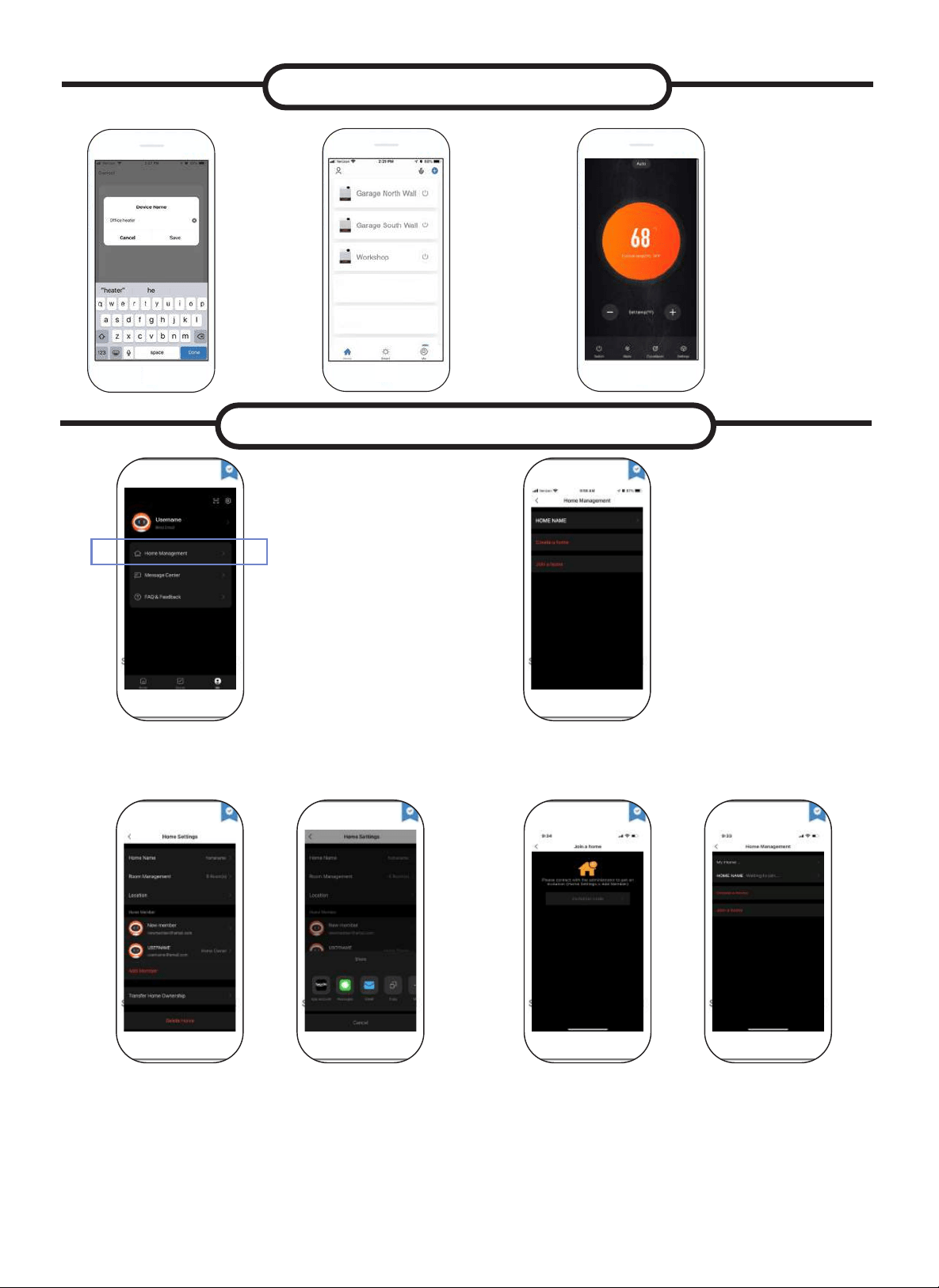
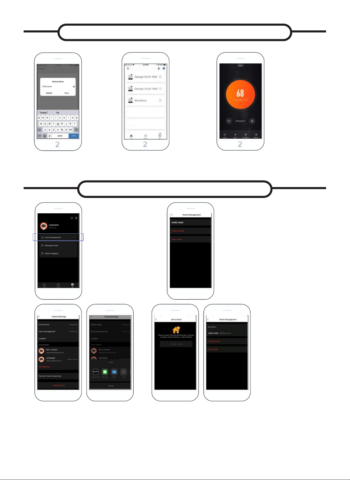
CONNECTING MULTIPLE DEVICES TO THE HEATER
To Connect Multiple Devices
go to the Me tab and click on
Home Management.
From there, select Create a Home where you can enter
a Home Name and set a location if you desire. After
doing so, you should see the Home Name at the top of
the page. Select your Home Name.
This will take you to a Home Settings
Page where you can select Add Member to connect a
new device. You will then be prompted to select how to
send the invite link to the member you want to add.
Typically, text message is the easiest way to send the
code, but there are multiple options to choose from.
For text message invites, you will be sent a 6 digit code
where you can enter this in the Home Management > Join
Home Page. If you share via the App Account option the
recipient will get a message in the Dyna Glo Heat App
Message Center, located in the Me tab. Once you receive
this message you can go to the Home Management page
and you will see the Home Name to click on to join.
4
6
Enjoy your new Heat
6WRUP:LÀ+HDWHU
If you have any ques-
tions or concerns, feel
free to contact us at:
435-752-6611
4
6
Enjoy your new Heat
6WRUP:LÀ+HDWHU
If you have any ques-
tions or concerns, feel
free to contact us at:
435-752-6611
4
6
Enjoy your new Heat
6WRUP:LÀ+HDWHU
If you have any ques-
tions or concerns, feel
free to contact us at:
435-752-6611
4
6
Enjoy your new Heat
6WRUP:LÀ+HDWHU
If you have any ques-
tions or concerns, feel
free to contact us at:
435-752-6611
4
6
Enjoy your new Heat
6WRUP:LÀ+HDWHU
If you have any ques-
tions or concerns, feel
free to contact us at:
435-752-6611
4
6
Enjoy your new Heat
6WRUP:LÀ+HDWHU
If you have any ques-
tions or concerns, feel
free to contact us at:
435-752-6611
1 2
3 4
MOBILE APP OPERATING INSTRUCTIONS
You can
also connect
multiple Dyna
Glo Heaters
for all your
cold spot
needs.
Now you can control
your heater with your
phone from anywhere!
You can adjust
temperatures, set timers,
and stay warm with a tap
of your nger!
To use the mobile
app to control your
heater, you must be
disconnected from the
external thermostat by
making sure the switch
on the back of the
unit is set to internal
thermostat setting.
4
6
Enjoy your new Heat
6WRUP:LÀ+HDWHU
If you have any ques-
tions or concerns, feel
free to contact us at:
435-752-6611
10
1110
4
6
Enjoy your new Heat
6WRUP:LÀ+HDWHU
If you have any ques-
tions or concerns, feel
free to contact us at:
435-752-6611
11
12
You can
now rename
your heater
to match the
room it is in.
4
6
Enjoy your new Heat
6WRUP:LÀ+HDWHU
If you have any ques-
tions or concerns, feel
free to contact us at:
435-752-6611
9
4
6
Enjoy your new Heat
6WRUP:LÀ+HDWHU
If you have any ques-
tions or concerns, feel
free to contact us at:
435-752-6611
15
1. Before cleaning, make sure the power has been turned off at the circuit breaker
panel and that the heating element of the heater is cool.
2. To maintain the external appearance of the heater, the unit occasionally needs to
be wiped with a dry duster. During the summer months, or at other times when
the appliance is not in use and is completely cold, it should be the wiped over
with a damp cloth.
3. Do not use abrasive clearing powders or furniture polish. Do not use chemical or
abrasive products, metallic scourers and so on, which may deteriorate the sur-
face, to clean the appliance.
4. During the summer months, or at other times when the appliance is not in use,
disconnect the power supply. Keep the appliance in a dry and cool place.
5. All other servicing should be performed by qualied service personnel. Do not try
to repair the heater yourself.
NOTE: The motor is permanently lubricated, and no further lubrication is needed.
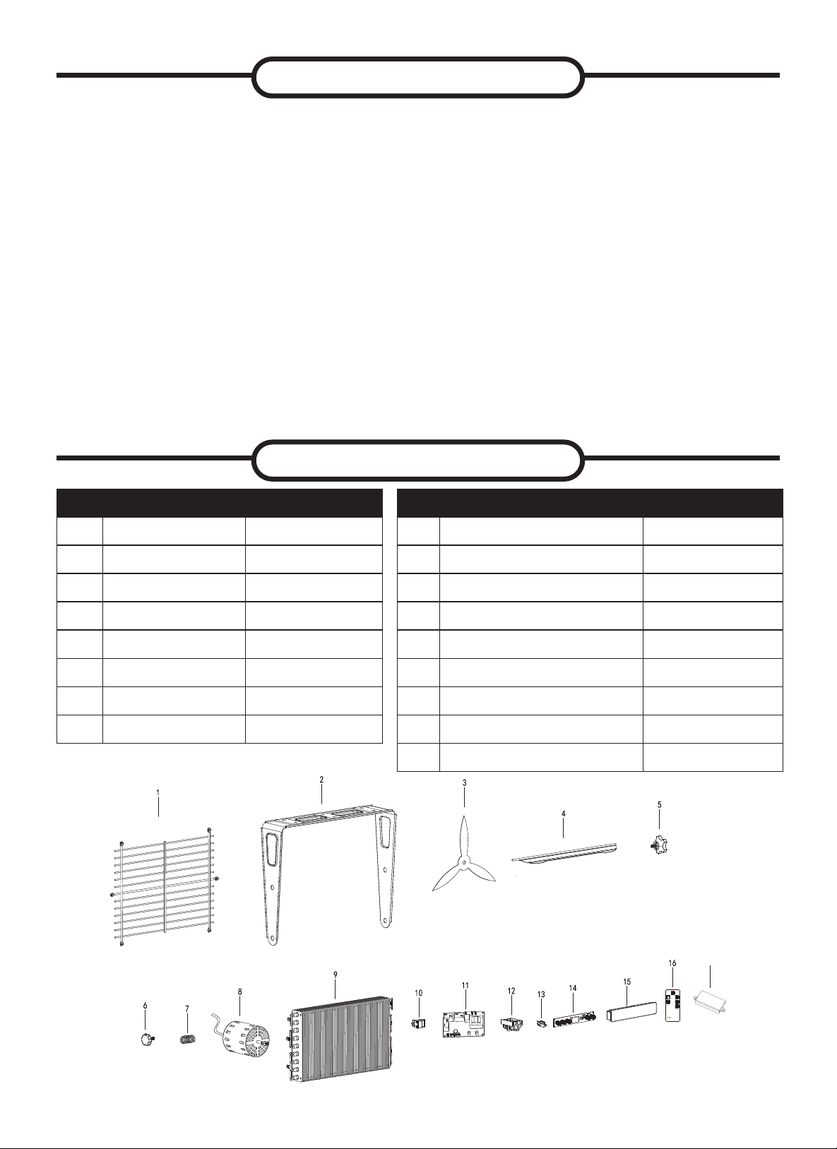
Part Description Part#
1 Back mesh
EG10000DH001AC
2 Hanging plate
EG10000DH002AC
3 Fan Blade
EG10000DH003AC
4 Air guide plate
EG10000DH004AC
5 Large handle seat
EG5000005AC
6 Small handle seat
EG5000006AC
7 Spring
EG5000007AC
8 Motor
EG10000DH005AC
Part Description Part#
9 Heater
EG10000DH006AC
10 Selection Switch
EG5000011AC
11 Main Board EG7500WB001AC
12 Terminal block EG5000014AC
13 Temperature CUT-OFF EG5000017AC
14 Control Panel Circuit Board EG10000WB002AC
15 Control Panel box EG7500DH003AC
16 Infrared Remote Control EG7500DH004AC
17 WiFi & Bluetooth Module EG7500WB005AC
MAINTENANCE
REPLACEMENT PARTS
17

16
TROUBLESHOOTING
PROBLEM
DISPLAY
CODE
ROOT CAUSE CORRECTIVE ACTION
Unit is not
heating
Display
shows”EE”
The thermostat sensor is bro-
ken or disconnected.
Please call customer service.
Display
shows"EF"
The overheat protection has
activated.
Inspect the garage heater and check
that the air inlets and outlets are not
blocked as this may cause overheat-
ing. Switch off the circuit breaker to the
garage heater for 30 minutes and allow
it to cool down. Turn the power back on
and operate.
Display
shows "LOC"
Heater is in Lock Mode
Hold the POWER button for 10 seconds to
unlock the heating function.
Display
shows "FA"
and blows
cold air
The heater is set to FAN ONLY
mode
Change the setting and switch to "AUT"
heating mode
The heater
will not start
The room temperature has
already reached the set ther-
mostat
temperature
Adjust the temperature setting to
make sure the thermostat setting
temperature is higher than current room
temperature.
The heater
will not start
The breaker has tripped
Rest the breaker at the fuse panel and
restart the heater
Garage
heater emits
a
burning
smell
During production dust and/
or oil debris gathered on
heating coils.
Make sure the room is well
ventilated. Allow the garage heater to
run until the smell is dissipated.
Check and make sure there
is no combustible material
within 0.9 meters (3 feet) of
the garage heater.
Remove the combustible material
around the garage heater.
This heater must be
mounted at least 8 feet
off the oor, for specic
clearances, please check
the "LOCATING HEATER"
section in the instruction
manual
Relocate the garage heater so there
is enough space between the heater
and adjacent wall and oor.
The unit
won’t stop
working
after turning
it off
The heater has built in cool
down cycle to protect the
heating element.
Wait for the fan to be turned off by
the temperature sensor, this can take
up to 5 to 10 minutes depending on
the environment temperature. It may
cycle on and off multiple times before
completely turning off.
Example:
Working within 15s, cooling down for
10s; Working for more than 15s, cool-
ing down for 90s.

17

PRODUCT NOTES
Warranty
LIMITED WARRANTY:
This limited warranty is extended to the original retail purchaser of this Forced Air/Convection/Radiant Heater and warrants against any defect
in materials and workmanship for a period of one (1) year from the date of retail sale.GHP Group, Inc., at it’s option, will either provide
replacement parts or replace or repair the unit, when properly returned to the retailer where purchased or one of our service centers
as directed by GHP Group,Inc., within one (1) year of retail purchase. (Shipping costs, labour costs,etc. are the responsibility of the purchaser.)
DUTIES OF THE OWNER:
This heating appliance must be operated in accordance with the written instructions furnished with this heater. This warranty shall not excuse
the owner from properly maintaining this heater in accordance with the written instructions furnished with this heater. A bill of sale, canceled
check or payment record must be kept to verify purchase data and establish warranty period. Original carton should be kept in case of
warranty return of unit.
WHAT IS NOT COVERED:
1. Damage resulting from use of improper fuel.
2. Damage caused by misuse or use contrary to the owners manual and safety guidelines.
3. Damage caused by a lack of normal maintenance.
4. Fuses
5. Use of non-standard parts or accessories.
6. Damage caused in transit. Freight charges on warranty parts or heaters to and from the factory shall be the responsibility of the owner.
This warranty does not imply or assume any responsibility for consequential damages that may result from the use, misuse, or the lack of
routine maintenance of this heating appliance. A cleaning fee and the cost of parts may be charged for appliance failures resulting from lack of
maintenance. This warranty does not cover claims which do not involve defective workmanship or materials. FAILURE TO PERFORM
GENERAL MAINTENANCE (INCLUDING CLEANING) WILL VOID THIS WARRANTY.
THIS LIMITED WARRANTY IS GIVEN TO THE PURCHASER IN LIEU OF ALL OTHER WARRANTIES, EXPRESSED OR IMPLIED,
INCLUDING BUT NOT LIMITED TO THE WARRANTIES OF MERCHANTABILITY OF FITNESS FOR A PARTICULAR PURPOSE. THE
REMEDY PROVIDED IN THIS WARRANTY IS EXCLUSIVE AND IS GRANTED IN LIEU OF ALL OTHER REMEDIES. IN NO EVENT
WILL GHP GROUP, INC. BE LIABLE FOR INCIDENTAL OR CONSEQUENTIAL DAMAGES.
Some states do not allow limitations on how long an implied warranty lasts, so the above limitation may not apply to you. Some states do not
allow the exclusion or limitation of incidental or consequential damages so the above limitation or exclusion may not apply to you.
CLAIMS HANDLED AS FOLLOWS:
1. Contact your retailer and explain the problem.
2. If the retailer is unable to resolve the problem, contact our Customer Service Dept. detailing the heater model, the problem, and proof
of date of purchase.
3. A representative will contact you. DO NOT RETURN THE HEATER TO GHP GROUP, INC. unless instructed by our Representative.
This warranty gives you specic legal rights and you may also have other rights which vary from state to state.
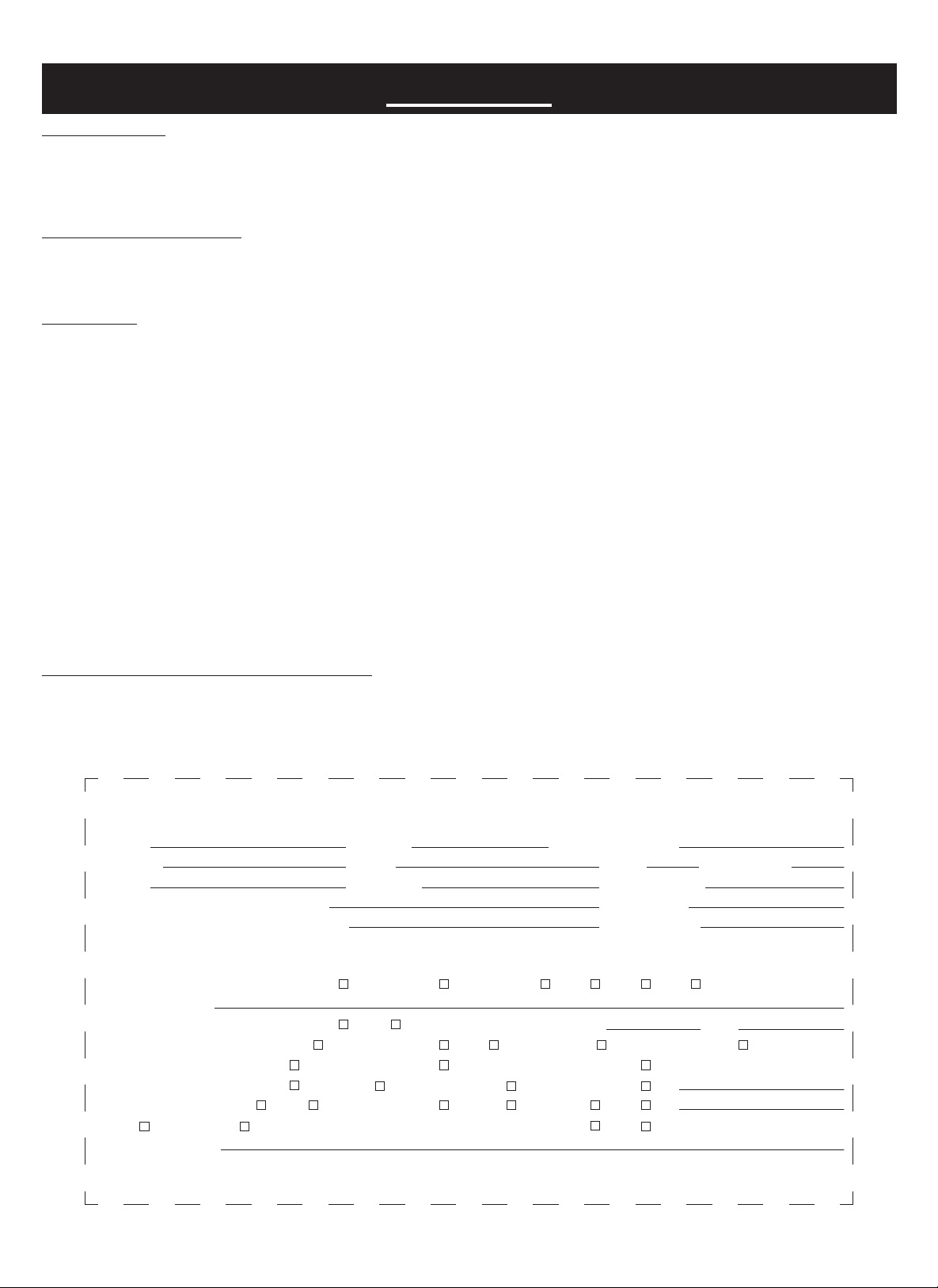
TO REGISTER THE WARRANTY ON YOUR HEATER, PLEASE FILL OUT THIS CARD COMPLETELY
AND MAIL WITHIN 14 DAYS FROM DATE OF PURCHASE OR REGISTER ON-LINE AT www.ghpgroupinc.com
NAME: _______________________________ PHONE: ( ) _________________ EMAIL: ____________________________________
ADDRESS: ___________________________ CITY: ________________________ STATE: _____________________ ZIP: ___________
MODEL: ______________________________ SERIAL#: _____________________ DATE PURCHASED: _________________________
DEALER PURCHASED FROM: _________________________________________ TYPE OF STORE: __________________________
CITY & STATE WHERE PURCHASED: ___________________________________ PRICE PAID: _______________________________
Please Take 1 Minute To Give Us Your Answers To The Following Questions.
All Responses Used Solely For Market Research And Are Held In Strict Condence.
Who primarily decided this purchase? Male Female 18-24 25-39 40-59 60 and over of age?
Do you own any other portable heaters? Yes No If yes, type ______________________ brand ____________________________
How do you intend to use your new heater? Construction Site Farm Warehouse/Commercial Garage/Outbuilding Other
How did you become aware of this heater? In-Store Display Newspaper Ad Magazine Ad Friend/Relative
TV Commercial Store Salesperson Other ____________________________________________________________________
What made you select this heater? Style Size/Portability Price Package Brand Other __________________________
Do you: Own Rent Would you recommend this heater to a friend? Yes No
Please give us your comments _____________________________________________________________________________________
THANK YOU FOR COMPLETING THIS FORM!
Information will be held condential.
WARRANTY REGISTRATION
IMPORTANT: We urge you to ll out your warranty registration card within fourteen (14)
days of date of purchase. You can also register your warranty on the internet at
www.ghpgroupinc.com. Complete the entire serial number. Retain this portion of the card
for your records.
Place
Postage
Stamp
Here
SAVE THIS CARD!
GHP Group, Inc.
6440 W Howard St
Niles, IL 60714-3302
Tel: (877) 447-4768
www.ghpgroupinc.com
GHP Group, Inc.
6440 W Howard St
Niles, IL 60714-3302
Antes de utilizar por primera vez este calentador, lea este MANUAL DEL
USUARIO atentamente. Este MANUAL DEL USUARIO ha sido diseñado
para instruirle la forma adecuada de ensamblar el calentador, brindarle
mantenimiento, guardarlo y lo más importante: cómo hacerlo funcionar de
manera segura y ecaz. Conserve este manual para referencia futura.
CONSUMIDOR: Conserve este manual para referencia futura.
¿Preguntas, problemas, partes faltantes? Antes de regresar al distribuidor,
llame a nuestro departamento de servicio al 877-447-4768 de 8:00 a.m. a
4:30 p.m. hora estándar del centro, de lunes a viernes o envíenos un correo
electrónico a [email protected].
Calefactor de garaje eléctrico
INSTRUCCIONES DE INSTALACIÓN Y MANTENIMIENTO
EG10000WB
10,000W / 240V / 34,120 BTU
CSA C22.2 No. 46-13
UL 2021
21
INSTRUCCIONES IMPORTANTES
GUARDE ESTAS INSTRUCCIONES
ADVERTENCIA PARA DUEÑOS DE MASCOTAS: Algunas mascotas pequeñas, incluidos los
pájaros, son muy sensibles a la exposición de los humos que se producen durante el uso de
electrodomésticos por primera vez. Estos humos no son dañinos para los seres humanos, pero
le recomendamos que no utilice el calefactor cerca de pájaros y mascotas pequeñas durante el
primer uso de la unidad hasta que los recubrimientos anticorrosivos se quemen por completo.
ESTE CALEFACTOR REQUIERE INSTALACIÓN CABLEADA (SIN ENCHUFE). LA
INSTALACIÓN DE ESTE PRODUCTO DEBE REALIZARLA UN ELECTRICISTA
CERTIFICADO EN CONFORMIDAD CON TODOS LOS CÓDIGOS ELÉCTRICOS LOCALES
Y NACIONALES.
Al usar electrodomésticos, siempre se deben respetar las precauciones básicas para reducir el
riesgo de incendio, choques eléctricos y lesiones personales, incluidas las siguientes:
1. Lea todas las instrucciones antes de instalar o usar este calefactor.
2. Este calefactor se calienta cuando está en uso. Para evitar quemaduras, no toque las
supercies calientes con la piel descubierta. Mantenga los materiales combustibles, como
cable eléctricos, muebles, almohadas, ropa de cama, papeles, vestimenta, cortinas, etc. a
una distancia mínima de 3 pies (0,90 m) de la parte frontal del calefactor, y alejados de los
laterales y de la parte trasera.
3. Se debe tener sumo cuidado al usar calefactores junto a niños o personas inválidas, o
cerca de ellos, y en todo momento en que el calefactor se deje prendido y desatendido.
4. Siempre desconecte la alimentación al calefactor cuando no esté en uso.
5. No ponga en funcionamiento ningún calefactor después de que haya fallado. Desconecte
la energía en el panel de servicio y haga que un electricista acreditado inspeccione el
calentador antes de reutilizarlo.
6. No lo utilice al aire libre.
7. Este calefactor no está diseñado para usarse en baños, lavaderos o lugares cubiertos
similares. No ubique el calefactor en un lugar donde pueda caerse dentro de una bañera u
otro contenedor de agua.
8. No inserte ni permita que ingresen objetos extraños en ninguna abertura de ventilación o
escape porque podrían provocar un choque eléctrico, un incendio o daños en el calefactor.
9. Para evitar posibles incendios, no bloquee las tomas de aire ni el conducto de escape de
ninguna manera. No haga funcionar el calefactor sobre supercies blandas, como una
cama, donde las aberturas puedan bloquearse.
10. El calefactor contiene piezas internas que se calientan, forman arcos eléctricos o generan
chispas. No lo use en áreas donde se utilice o se guarde gasolina, pintura o líquidos
inamables.
11. Utilice este calefactor solo como se describe en este manual. Otros usos no
recomendados por el fabricante podrían provocar incendios, choques eléctricos o lesiones
personales.
12. Para desconectar el calentador, apague los controles y apague el circuito del calentador
en el panel de desconexión principal.
13. Si se enciende la luz roja de alarma en la parte frontal de la unidad, apague
inmediatamente el calentador e inspeccione si hay objetos en el calentador o adyacentes
al mismo que puedan haber bloqueado el ujo de aire o haber causado altas temperaturas.
NO OPERE EL CALENTADOR CON LA LUZ DE ALARMA ILUMINADA.
22
Este producto puede exponerlo a usted a agentes químicos incluyendo ftalato de diisononilo
(DINP), reconocido por el estado de California como causante de cáncer, así como ftalatos de
diisodecilo (DIDP), reconocidos por el estado de California como causantes de defectos congénitos
y otros daños al sistema reproductor.
Para obtener más información, visite www.p65Warnings.ca.gov
ADVERTENCIA

23
EN CONFORMIDAD CON LA FCC
TENGA EN CUENTA QUE LOS CAMBIOS O MODIFICACIONES DE ESTE PRODUCTO
QUE NO ESTÉN EXPRESAMENTE APROBADOS POR LA PARTE RESPONSABLE DE LA
CONFORMIDAD PODRÍAN ANULAR LA AUTORIDAD DEL USUARIO PARA OPERAR EL
EQUIPO.
NOTA: Este equipo ha sido probado y encontrado conforme con los límites para un dispositivo
digital de clase B, de conformidad con la parte 15 del Reglamento de la FCC. Estos límites están
diseñados para proporcionar una protección razonable contra interferencias perjudiciales en una
instalación residencial. Este equipo genera, utiliza y puede irradiar energía de radiofrecuencia y, si
no se instala y utiliza de acuerdo con las instrucciones, puede causar interferencias perjudiciales a
las comunicaciones de radio. Sin embargo, no hay garantía de que no se produzcan interferencias
en una instalación en particular.
1. Si este equipo causa interferencias perjudiciales en la recepción de señales de radio o
televisión, lo cual puede determinarse apagando y encendiendo el equipo, se recomienda
al usuario que intente corregir la interferencia mediante una o más de las siguientes
medidas:
2. Reorientar o reubicar la antena receptora.
3. Aumentar la separación entre el equipo y el receptor.
4. Conectar el equipo a un tomacorriente en un circuito diferente de aquel al que está
conectado el receptor.
5. Consultar con el distribuidor o con un técnico con experiencia en radio y televisión para
obtener ayuda.
Este dispositivo cumple con la parte 15 del Reglamento de la FCC. Su funcionamiento está sujeto
a las dos condiciones siguientes: (1) este dispositivo no puede causar interferencias perjudiciales,
y (2) este dispositivo debe aceptar cualquier interferencia recibida, incluidas las interferencias que
puedan causar un funcionamiento no deseado.
1. Importador: GHP Group, Inc.
2. Dirección: 6440 W Howard St. Niles IL, 60714
3. Teléfono: (847) 324 – 5900
ID FCC del módulo transmisor: 2ANDL-WBR1-IPEX
2424
ARTÍCULO PÁGINA
ESPECIFICACIONES ..................................................................... 23
INFORMACIÓN GENERAL SOBRE SEGURIDAD ......................... 23
UBICACIÓN DEL CALEFACTOR .................................................... 24
PRE-INSTALACIÓN ........................................................................ 21
INSTALACIÓN ................................................................................. 22
INSTRUCCIONES DE USO ............................................................ 31
MANTENIMIENTO Y LIMPIEZA ..................................................... 34
PIEZAS DE REPUESTO ................................................................. 34
SOLUCIÓN DE PROBLEMAS ........................................................ 35
1. Utilice solo cables de cobre calicados para 60°C como mínimo.
2. El ujo de aire del calefactor se debe orientar de modo que quede paralelo a la
pared adyacente o en dirección contraria a ella.
3. Respete los requisitos de espacio libre hacia la pared, el piso y el techo.
4. Todo el cableado se debe realizar de conformidad con los códigos nacionales y
locales de electricidad de Estados Unidos y el calefactor debe estar conectado
a tierra como precaución contra posibles choques eléctricos. El circuito del
calefactor se debe proteger con fusibles apropiados.
5. La estructura de montaje y la tornillería de anclaje deben poder soportar de modo
conable el peso del calefactor y del soporte de montaje, si se lo utiliza.
CONTENIDO
ESPECIFICACIONES
INFORMACIÓN SOBRE SEGURIDAD
ESTE CALEFACTOR REQUIERE UNA INSTALACIÓN CABLEADA FIJA (SIN ENCHUFE). A LA
INSTALACIÓN LA DEBE REALIZAR UN ELECTRICISTA CERTIFICADO Y SE DEBE EFECTUAR
DE CONFORMIDAD CON TODOS LOS CÓDIGOS LOCALES Y NACIONALES DE ELECTRICIDAD.
NOTA: COMPATIBLE CON UN TERMOSTATO DE PARED BIPOLAR CON TENSIÓN DE LÍNEA DE
240 V. DEBE SER INSTALADO POR UN ELECTRICISTA CERTIFICADO.
LEA Y COMPRENDA TODAS LAS INSTRUCCIONES DE INSTALACIÓN Y FUNCIONAMIENTO, Y
RESPETE TODAS LAS INSTRUCCIONES DE SEGURIDAD.
ADVERTENCIA
Índice
Conguración del interruptor
Voltios Fase Hz Amperios BTU/hora
10000W II 240 1 60 41.7 34120
7500W I 240 1 60 31.3 25590
7500W II 208 1 60 36.1 25590
5600W I 208 1 60 26.9 19107
2525
DISTANCIA
MÍNIMA
A PARED
DISTANCIA
MÍNIMA
A PARED
13 pulg.
VISTA LATERAL
10-3/16 pulg.
24 pulg.
4½ pulg.
¾ pulg.
1¾ pulg.
½ pulg.
7-3/8 pulg.
4½ pulg.
DISTANCIA
MÍNIMA
DESDE LA
DESCARGA A
UN OBJETO
DISTANCIA
MÍNIMA AL PISO
8 pies
ALTURA MÁXIMA DE MONTAJE DESDE:
Unidad para proporcionar aire vertical = 11 pies
Unidad para proporcionar aire horizontal = 8 pies
Nota: El espacio libre
mínimo al techo cuando no
se utilizan los soportes de
montaje es de 1-5/8 pulg.
14 pulg.
12½ pulg.
VISTA FRONTAL
Figura 2
Instale el calefactor fuera de las zonas de tránsito y mantenga los espacios libres
indicados en la gura 2. La dirección del ujo de aire no debe estar restringida por
columnas o máquinas. El ujo de aire solo debe rozar las paredes y no dirigirse
directamente a ellas. Cuando se utiliza más de un calefactor en un área, los
calefactores se deben disponer de modo que la descarga de aire de cada uno
acompañe el ujo de aire de los otros para proporcionar una circulación óptima de
aire caliente, como se indica en la gura 3.
INFORMACIÓN SOBRE SEGURIDAD
UBICACIÓN DEL CALEFACTOR
INSTALAR INCORRECTAMENTE O NO RESPETAR LOS PROCEDIMIENTOS DESCRITOS EN
ESTE MANUAL DE INSTRUCCIONES PUEDE DAR LUGAR A CHOQUES ELÉCTRICOS GRAVES.
ADVERTENCIA
6. Se debe desconectar la alimentación eléctrica y bloquear la caja de servicio
eléctrico antes de inspeccionar el calefactor, limpiarlo o realizarle mantenimiento.
Esta es una precaución para evitar choques eléctricos graves.
7. Este calefactor no es apropiado para utilizarlo en ubicaciones peligrosas tal como
las dene la Asociación Nacional de Protección contra Incendios (NFPA, por su
sigla en inglés) de Estados Unidos. El calefactor contiene piezas internas que se
calientan, forman arcos eléctricos o generan chispas. No lo use en áreas donde
se utilice o se guarde gasolina, pintura o líquidos inamables.
8. Este calefactor no es apropiado para utilizarlo en atmósferas corrosivas, como
zonas marinas, invernaderos o áreas de almacenamiento de productos químicos.
9. Este calefactor debe estar ubicado a 8 pies del piso, como mínimo. Para las
distancias libres especícas, vea la gura 2.
2626
Parte Descripción Cantidad
A Calentador de garaje 1
B Soporte de montaje 1
C Control remoto infrarrojo 1
D Tornillo 6
E Arandela 12
PRE-INSTALACIÓN
Figura 3
UBICACIÓN DEL CALEFACTOR
2727
Techo de madera
Techo de madera
Figura 4a. Montaje de un solo tornillo Figura 4b. Montaje de dos tornillo
MONTAR EL SOPORTE
Consulte las guras 4a y 4b.
1. Localice un montante de madera en la viga del techo de madera. Si no puede
localizarlo, debe instalar una pieza de madera en el techo porque el calefactor se
debe sujetar de forma segura.
2. Retire el soporte de montaje de la unidad calefactora; para esto, aoje los tornillos
del soporte con una llave y deslice la manija por afuera y por encima de las
cabezas de los tornillos.
3. Coloque una arandela en los tornillos antes de insertarlos a través de los oricios
del soporte de montaje y atorníllelos rmemente en la viga del techo.
NOTA: Si desea que el calefactor gire hacia la derecha o hacia la izquierda, se
recomienda agregar una arandela a ambos lados del soporte. Es posible que se
necesite un tirafondo más largo para sujetar la unidad correctamente. Consulte la
gura 4a.
COLGAR EL CALEFACTOR
1. Fije la unidad calefactora al soporte de
montaje.
2. Eleve el calefactor y colóquelo en el soporte
de montaje.
3. Alinee los tornillos del soporte con las
ranuras tipo bocallave del soporte de
montaje.
4. Ajuste los tornillos del soporte con una
llave para que la unidad quede suspendida
rmemente en el nivel horizontal o vertical.
5. El calentador se puede montar con
diferentes ángulos enumerados en el
dibujo de la página 25 siempre quemientras
mantiene la autorización adecuada que
gura en página 28.
Figura 5
AJUSTAR LA DIRECCIÓN DEL FLUJO DE AIRE
1. Para girar la unidad, cuando esta se ha instalado con un solo tirafondo (como se muestra
en la gura 4a), simplemente gire todo el calefactor según sea necesario. La unidad no
se puede girar en sentido horizontal si se instaló con 2 tirafondos.
2. Para inclinar la unidad verticalmente, aoje los tornillos del soporte (consulte la gura 5).
INSTALACIÓN
UTILICE LAS RANURAS
SUPERIORES TIPO
BOCALLAVE SI ES
CALEFACTOR SE VA A
INCLINAR HACIA ABAJO
QUITE EL TORNILLO PARA ABRIR LA PUERTA
AFLOJE LAS PERILLAS Y SELECCIONE
EL ORIFICIO DE MONTAJE BASADO EN EL
ÁNGULO DE CALEFACCIÓN DESEADO. CON-
SULTE EL DIAGRAMA EN LA PÁGINA 28.
2828
MÚLTIPLES ÁNGULOS VERTICALES
3. Ajuste las rejillas a la posición deseada (consulte la
gura 6).
NOTA: Las rejillas están diseñadas para que no se
puedan cerrar por completo. No intente hacerlo porque
puede dañar la unidad.
INSTALACIÓN
Figura 6
PARA EVITAR POSIBLES CHOQUES ELÉCTRICOS, DESCONECTE LA ALIMENTACIÓN AL
CALEFACTOR EN LA CAJA DE SERVICIO ELÉCTRICO ANTES DE INTENTAR AJUSTAR LA
SALIDA DE CALOR DE LA UNIDAD.
ADVERTENCIA
29
GND
E
L1
L2
1
2
240AC or 208AC
60HZ
External
thermostat
PCB
Selected
switch
2500W
3750W
3750W
Si utiliza un control de temperatura externo (termostato externo) para detener o
activar el calefactor, siga los puntos de atención que se detallan a continuación:
1. Asegúrese de que la perilla de control de temperatura del calefactor (perilla del
termostato) esté totalmente girada en el sentido de las agujas del reloj.
2. Conecte el cable según el diagrama de cableado a continuación.
CONEXIÓN DE LA ALIMENTACIÓN
INSTALACIÓN
Interruptor de selección
(termostato del calefactor, termostato externo)
Termostato del
calefactor
Termostato
externo
Termostato
externo
Termostato
externo
Estacion terminal
Termostato externo
Interruptor de
selección
Interruptor de
selección
NOTA: Cuando se utilice el
termostato DGT-240, debe
conectar “Load Black” a “3” en
el termostato.
3030
1. Quite el tornillo del frente de la unidad para conectar la alimentación al calefactor.
2. Fije los conectores de cables a la unidad (consulte la gura 7). Seleccionar fuente
de alimentación alambre para cumplir con los códigos eléctricos locales y nacionales
usando la clasicación del calentador dada en la etiqueta de clasicación.
3. Conecte el cable al bloque de terminales de alimentación ubicado en la base del
calefactor; consulte la gura 7.
4. Conecte la alimentación en la caja de servicio eléctrico.
NOTA: A todo el cableado lo debe realizar un electricista certicado y se debe
efectuar de conformidad con los códigos nacionales y locales de electricidad. Es
posible que se necesiten conductos en el caso de determinadas aplicaciones;
consulte la gura 7. Verique los códigos locales de electricidad. Si se tiende el
cableado en conductos y se desea girar el calefactor, asegúrese de comprar una
cantidad suciente de conducto exible que permita girar el calefactor.
INSTALACIÓN
TEMPERATURAS ELEVADAS: RIESGO DE INCENDIO. MANTENGA LOS MATERIALES
COMBUSTIBLES, COMO MUEBLES, ALMOHADAS, ROPA DE CAMA, PAPELES, VESTIMENTA,
CABLES ELÉCTRICO, Y CORTINAS, A UNA DISTANCIA MÍNIMA DE 3 PIES (0,90 M) DE LA
PARTE FRONTAL Y SUPERIOR DEL CALEFACTOR, Y ALEJADOS DE LOS LATERALES Y DE
LA PARTE TRASERA.
ADVERTENCIA
PARA REDUCIR EL RIESGO DE INCENDIO, NO ALMACENE NI USE GASOLINA U OTROS
VAPORES Y LÍQUIDOS INFLAMABLES CERCA DEL CALENTADOR.
ADVERTENCIA
CONEXIÓN DE LA ALIMENTACIÓN
3. El control de la temperatura externa (termostato externo): un termostato certica-
do debe ser utilizado.
4. El cable principal del control de temperatura externo (termostato externo) no
puede ser de un calibre inferior a 14 AWG.
PARA PROTEGER EL ELEMENTO CALEFACTOR
Cuando esté poniendo en marcha el calefactor, girando el control de temperatura
en el sentido de las agujas del reloj lentamente hasta la temperatura deseada, la
unidad pondrá en marcha el ventilador primero y luego pondrá en marcha el elemento
calefactor. Cuando apague el calefactor, al girar el control de temperatura en sentido
contrario a las agujas del reloj lentamente.
CICLO DE ENFRIAMIENTO
El ciclo de enfriamiento puede tomar hasta 5 minutos y continuar encendiéndose y
apagándose según sea necesario para enfriarse adecuadamente.
ESTE ELECTRODOMÉSTICO DEBE ESTAR CONECTADO A TIERRA.
¡EL APARATO DEBE CONECTARSE A UN CIRCUITO O DISPOSITIVO DE PROTECCIÓN DE
CORRIENTE ANTES DE CONECTARSE A LA FUENTE DE ALIMENTACIÓN!
ADVERTENCIA
3131
Conectores, cable y demás elementos
utilizados para el cableado del calefactor
Figura 7
Conector de
conducto
Conducto
Conducto exible
Cable NM exible
Conector de cable NM exible
Conector de Conducto exible
BLANCO
NEGRO
VERDE (o de cobre
sin revestimiento)
3pi
CONEXIÓN DE LA ALIMENTACIÓN
INSTALACIÓN
INSTRUCCIONES DE USO
ANTES DE SU USO, EL CALEFACTOR SE DEBE INSTALAR CORRECTAMENTE.
ADVERTENCIA
Panel de control

3232
INSTRUCCIONES DE USO
Revise que la parrilla de salida del calefactor de garaje no esté tapada ni obstruida de ninguna manera,
y asegúrese de que la unidad esté encendida.
El calefactor de garaje se puede acceder de tres maneras:
• Usando el panel de control del panel táctil, ubicado en la parte frontal del calentador del garaje,
debajo de las placas de guía de aire.
• Uso del mando a distancia multifunción.
• Uso de la aplicación en su dispositivo móvil
Icono Qué hará el calentador:
Figura 1
Botón de encendido principal:
Este botón suministra energía para todas las funciones del
calefactor de garaje. Debe estar encendido para que funcione el
calefactor de garaje.
Figura 2
Botón de control del calefactor:
Este botón ajusta los 4 niveles de calentamiento: AH, H, L, FA : AU
(el calefactor se ajustará entre bajo (7500 W se muestra “L”) y alto
(10000 W se muestra “H”) en función de la temperatura ambiente);
H (alta, 10000 W se muestra “H”); L (baja, 7500 W se muestra “L”);
FA (ventilador solamente).
Figura 3
Pantalla de temperatura/temporizador:
Esta pantalla LED muestra el punto de temperatura establecido y
las funciones del temporizador. Cuando se activa alguna de estas
funciones, la pantalla muestra el punto establecido durante cinco
segundos y luego se oscurece completamente. Cualquier cambio
en la temperatura o temporizador reactivará la pantalla, la cual se
oscurece nuevamente después de cinco segundos.
Figura 4
Botón de control ABAJO:
Este botón se usa para reducir la temperatura o el tiempo,
ajustando el rango de temperatura entre 10°C y 35°C (50°F y
95°F), es decir, cada etapa reduce 1°F (/1°C).
Figura 5
Botón de control ARRIBA:
Este botón se usa para aumentar la temperatura o el tiempo,
ajustando el rango de temperatura entre 10°C y 35°C (50°F y
95°F), es decir, cada etapa aumenta 1°F (/1°C).
Figura 6
Botón de temporizador:
Este botón controla el ENCENDIDO/APAGADO y la conguración
de 8 tiempos desde 1 hora hasta 8 horas. Cuando el temporizador
se encienda por primera vez, lo hará con la conguración de
tiempo más baja (1 hora). Cada vez que se pulse el botón del
temporizador, el tiempo aumentará 1 hora hasta la conguración
más alta (8 horas). Una vez que haya transcurrido el tiempo,
todas las funciones del calefactor de garaje se apagarán
automáticamente.
33
INSTRUCCIONES DE FUNCIONAMIENTO DE LA APLICACIÓN MÓVIL
Conecte su teléfono a una
red wi de 2,4 GHz.
* para algunos rúters de doble
banda, es posible que deba crear
manualmente una red dedicada a
2.4GHz.
Mientras el calentador esté
enchufado y encendido,
mantenga presionado el
símbolo de echas arriba
y abajo en la pantalla de
control durante 5 segundos.
Debería escuchar un pitido.
Descargue la aplicación
Dyna Glo Heater en Google
Play o en iOS App Store.
Haga clic en “Aceptar” en
el Acuerdo del Usuario y la
Política de Privacidad.
Escriba el código de
vericación.
Cree una cuenta de
Dyna-Glo o inicie
sesión en una cuenta
existente.
Haga clic en “Añadir
dispositivo” en la
página de inicio.
Para crear una cuenta nueva:
Escriba la dirección de correo electrónico y
marque la casilla de vericación para aceptar la
Política de Privacidad y el Acuerdo del Usuario.
Se enviará un código de vericación a la
dirección de correo electrónico suministrada.
Permita que Dyna-Glo Heat
acceda a Bluetooth y a la
ubicación del dispositivo.
Escriba el código de
vericación.
Después del paso 7, aparecerá
una ventana emergente en su
teléfono buscando el dispositivo
para emparejar. Una vez que
aparezca, haga clic en Añadir.
Su pantalla debe mostrar lo
siguiente: si muestra alguna
noticación de error, consulte
nuestra guía de solución de
problemas con WiFi en línea.
4
6
Enjoy your new Heat
6WRUP:LÀ+HDWHU
If you have any ques-
tions or concerns, feel
free to contact us at:
435-752-6611
1
1
4
6
Enjoy your new Heat
6WRUP:LÀ+HDWHU
If you have any ques-
tions or concerns, feel
free to contact us at:
435-752-6611
8
8
4
6
Enjoy your new Heat
6WRUP:LÀ+HDWHU
If you have any ques-
tions or concerns, feel
free to contact us at:
435-752-6611
5
9
4
6
Enjoy your new Heat
6WRUP:LÀ+HDWHU
If you have any ques-
tions or concerns, feel
free to contact us at:
435-752-6611
4
6
Enjoy your new Heat
6WRUP:LÀ+HDWHU
If you have any ques-
tions or concerns, feel
free to contact us at:
435-752-6611
4
6
Enjoy your new Heat
6WRUP:LÀ+HDWHU
If you have any ques-
tions or concerns, feel
free to contact us at:
435-752-6611
4
6
Enjoy your new Heat
6WRUP:LÀ+HDWHU
If you have any ques-
tions or concerns, feel
free to contact us at:
435-752-6611
4
6
Enjoy your new Heat
6WRUP:LÀ+HDWHU
If you have any ques-
tions or concerns, feel
free to contact us at:
435-752-6611
4
6
Enjoy your new Heat
6WRUP:LÀ+HDWHU
If you have any ques-
tions or concerns, feel
free to contact us at:
435-752-6611
4
6
Enjoy your new Heat
6WRUP:LÀ+HDWHU
If you have any ques-
tions or concerns, feel
free to contact us at:
435-752-6611
4
6
Enjoy your new Heat
6WRUP:LÀ+HDWHU
If you have any ques-
tions or concerns, feel
free to contact us at:
435-752-6611
2 2
2
2
22
2
2
2 3
4c
4
54a
6
4b
7
34
CONEXIÓN DE VARIOS DISPOSITIVOS AL CALEFACTOR
Para conectar varios
dispositivos, vaya a la
pestaña Yo y haga clic
en Gestión de viviendas.
Desde allí, seleccione Crear una vivienda
donde puede ingresar un nombre de vivienda y
establecer una ubicación si lo desea. Después
de hacerlo, debería ver el nombre de vivienda
en la parte superior de la página. Seleccione su
nombre de vivienda.
Esto lo llevará a la página de Conguración
de inicio donde puede seleccionar
Añadir miembro para conectar un nuevo
dispositivo. A continuación, se le pedirá
que seleccione cómo enviar el enlace de
invitación al miembro que desea añadir.
Por lo general, la mensajería de texto es la forma más fácil de enviar el códi-
go, pero hay varias opciones para elegir. Para las invitaciones por mensajes
de texto, se le enviará un código de 6 dígitos que puede ingresar en la página
de inicio de Gestión de viviendas > Unirse. Si comparte a través de la opción
Cuenta de la aplicación, el destinatario recibirá un mensaje en el Centro de
mensajes de la aplicación Dyna Glo Heat, ubicado en la pestaña Yo. Una vez
que reciba este mensaje, puede ir a la página Gestión de viviendas y verá el
Nombre de vivienda para clicar en unirse.
4
6
Enjoy your new Heat
6WRUP:LÀ+HDWHU
If you have any ques-
tions or concerns, feel
free to contact us at:
435-752-6611
1
4
6
Enjoy your new Heat
6WRUP:LÀ+HDWHU
If you have any ques-
tions or concerns, feel
free to contact us at:
435-752-6611
2
4
6
Enjoy your new Heat
6WRUP:LÀ+HDWHU
If you have any ques-
tions or concerns, feel
free to contact us at:
435-752-6611
2
4
6
Enjoy your new Heat
6WRUP:LÀ+HDWHU
If you have any ques-
tions or concerns, feel
free to contact us at:
435-752-6611
2
4
6
Enjoy your new Heat
6WRUP:LÀ+HDWHU
If you have any ques-
tions or concerns, feel
free to contact us at:
435-752-6611
2
4
6
Enjoy your new Heat
6WRUP:LÀ+HDWHU
If you have any ques-
tions or concerns, feel
free to contact us at:
435-752-6611
2
1 2
3 4
También
puede
conectar
varios
calefactores
Dyna
Glo para
satisfacer
todas sus
necesidades
de
calefacción.
¡Ahora puede controlar
su calefactor con su
teléfono desde cualquier
lugar! ¡Puede ajustar las
temperaturas, congurar
temporizadores, y
mantenerse en calor con
un toque de su dedo!
Para usar la aplicación
móvil para controlar
su calefactor, debe
desconectarse del
termostato externo
asegurándose de que
el interruptor en la parte
posterior de la unidad
esté congurado para
la conguración del
termostato interno.
4
6
Enjoy your new Heat
6WRUP:LÀ+HDWHU
If you have any ques-
tions or concerns, feel
free to contact us at:
435-752-6611
1110
4
6
Enjoy your new Heat
6WRUP:LÀ+HDWHU
If you have any ques-
tions or concerns, feel
free to contact us at:
435-752-6611
12
Ahora
puede
cambiar el
nombre de
su calefactor
para que
coincida con
la habitación
en la que se
encuentra.
4
6
Enjoy your new Heat
6WRUP:LÀ+HDWHU
If you have any ques-
tions or concerns, feel
free to contact us at:
435-752-6611
4
6
Enjoy your new Heat
6WRUP:LÀ+HDWHU
If you have any ques-
tions or concerns, feel
free to contact us at:
435-752-6611
INSTRUCCIONES DE FUNCIONAMIENTO DE LA APLICACIÓN MÓVIL
3535
MANTENIMIENTO
1. Antes de realizar una limpieza, asegúrese de que la alimentación haya sido
desconectada en el panel de interruptores de circuito y de que el elemento
calefactor esté frío.
2. En cuanto al mantenimiento del aspecto externo del radiador, solo se necesita repasar,
de vez en cuando, la supercie utilizando un paño seco. El mejor momento para repasar
la unidad con un paño húmedo es cuando el electrodoméstico está completamente frío, y
esto ocurre en los meses de verano o en otras oportunidades en que no se lo utiliza por
tiempo prolongado.
3. No utilice polvos de limpieza abrasivos ni cera para muebles. Para limpiar el
electrodoméstico, no utilice productos químicos ni abrasivos, ni estropajos
metálicos que podrían dañar la supercie.
4. Durante los meses de verano o en otras oportunidades en que no se utilice el
electrodoméstico, desconecte el suministro de alimentación. Guarde el electrodoméstico
en un lugar seco y fresco.
5. Todos los demás servicios de mantenimiento deben ser realizados por técnicos calicados.
No intente reparar el calefactor usted mismo.
NOTA: El motor está permanentemente lubricado y no se necesita más lubricación.
PIEZAS DE REPUESTO
Pieza Descripción No. de pieza
1 Rejilla trasera
EG10000DH001AC
2 Placa de suspension
EG10000DH002AC
3 Aspa del ventilador
EG10000DH003AC
4
Placa de
conducción de aire
EG10000DH004AC
5 Manija grande
EG5000005AC
6 Manija pequeña
EG5000006AC
7 Resorte
EG5000007AC
8 Motor
EG10000DH005AC
Pieza Descripción No. de pieza
9
Calentador
EG10000DH006AC
10 Interruptor de selección
EG5000011AC
11 Tablero principal EG7500WB001AC
12 Bloque de terminales EG5000014AC
13
Corte de temperatura EG5000017AC
14
Panel de circuito del
panel de control
EG10000WB002AC
15 Caja del panel de control EG7500DH003AC
16 Control remoto infrarrojo EG7500DH004AC
17 Módulo Wi-Fi y Bluetooth EG7500WB005AC
17
SOLUCIÓN DE PROBLEMAS
36
PROBLEMA
CÓDIGO DE
PANTALLA
RAÍZ DEL PROBLEMA MEDIDA CORRECTIVA
La unidad no
está calentan-
do
La pantalla
muestra ”EE”
El sensor del termostato está
dañado o
desconectado.
Por favor llame al servicio al cliente.
La pantalla
muestra "EF"
La protección de sobrecalen-
tamiento se ha activado.
Inspeccione el calefactor de garaje y revise
que las entradas y salidas de aire no estén
bloqueadas ya que esto puede causar
sobrecalentamiento. Apague el interruptor
principal del circuito del calefactor de garaje
durante 30 minutos y deje que se enfríe.
Enciéndalo nuevamente y póngalo en fun-
cionamiento.
La pantalla
muestra
"LOC"
El calefactor está en modo
BLOQUEADO
Mantenga pulsado el botón de ENCENDI-
DO durante 10 segundos para desbloquear
la función de calefacción.
La pantalla
muestra "FA"
y sopla aire
frío
El calefactor está
congurado en modo
VENTILADOR
Cambie la conguración y cambie al modo
de calefacción "AUT"
El calefactor
no arranca
La temperatura de la
habitación ya ha alcanzado la
temperatura congurada en el
termostato
Ajuste la conguración de la temperatura
para asegurarse de que la conguración de
la temperatura del termostato es mayor que
la temperatura actual de la habitación.
El calefactor
no arranca
El interruptor automático se
ha disparado.
Reestablezca el interruptor principal en el
panel de fusibles y reinicie el calefactor
El calefactor
de garaje
emite un olor
a quemado
Durante la fabricación se acumuló
polvo y/o escombros en los
serpentines de calentamiento.
Asegúrese de que la habitación esté bien
ventilada. Ponga el calefactor de garaje en
funcionamiento hasta que el olor se haya
disipado.
Revise y asegúrese de que no
haya material combustible dentro
de un rango de 0.9 metros (3
pies) alrededor del calefactor de
garaje.
Retire el material combustible alrededor del
calefactor de garaje.
Este calefactor debe estar
instalado al menos a 8 pies
del suelo. Para distancias
libres especícas revise la
sección "UBICACIÓN DEL
CALEFACTOR" en el manual de
instrucciones
Reubique el calefactor de garaje de manera
que haya suciente espacio entre el cale-
factor y las paredes y suelo adyacentes.
La unidad
no dejará
de funcionar
después de
apagarla.
El calefactor tiene un ciclo
de enfriamiento integrado
para proteger el elemento
calefactor.
Espere a que el sensor de temperatura
apague el ventilador. Esto puede tomar
hasta de 5 a 10 minutos dependiendo de
la temperatura ambiental. Puede alternar
entre encendido y apagado múltiples
veces antes de apagarse completamente.
Ejemplo:
Funcionando durante 15 s, enfriándose
durante 10 s; funcionando durante más
de 15 s, enfriándose durante 90s.
37
NOTAS
38
GARANTÍA
GARANTÍA LIMITADA:
Esta garantía limitada se extiende al comprador minorista original de este calefactor de aire forzado/convección/radiante, que está garantizado contra defectos
de materiales y mano de obra por un período de un (1) año a partir de la fecha de la venta minorista (garantía de por vida solo para el quemador con boquilla de
bronce). GHP Group, Inc., a su discreción, proporcionará las piezas de repuesto o reparará la unidad, cuando esta sea devuelta a la tienda minorista donde se
compró o a uno de nuestros centros de servicio, según lo indique GHP Group, Inc., dentro de un período de un (1) año a partir de la compra minorista. (Los costos
de envío, los costos de mano de obra, etc. son responsabilidad del comprador).
OBLIGACIONES DEL PROPIETARIO:
Este artefacto de calefacción se debe utilizar de acuerdo con las instrucciones escritas incluidas con el calefactor. Esta garantía no eximirá al propietario del
mantenimiento adecuado del calefactor de acuerdo con las instrucciones escritas incluidas con el calefactor. Se debe conservar la factura de compra, el cheque
cobrado o el registro de pago para vericar la fecha de compra y establecer el período de la garantía. Se debe conservar la caja original en caso de que se desee
devolver la unidad en garantía.
QUÉ NO CUBRE:
1. Daños ocasionados por el uso del combustible incorrecto.
2. Daños ocasionados por el uso indebido o contrario al manual del propietario y a las pautas de seguridad.
3. Daños ocasionados por la falta de mantenimiento normal.
4. Fusibles
5. Uso de piezas o accesorios no estándar.
6. Daños ocasionados en el traslado. Los cargos de ete para las piezas o los calefactores en garantía trasladados hacia o desde la fábrica serán
responsabilidad del propietario.
Esta garantía no implica ni asume ninguna responsabilidad de daños indirectos que se podrían ocasionar por el uso, el uso indebido o la falta de mantenimiento
habitual de este artefacto de calefacción. Se podría cobrar una tarifa por limpieza y el costo de las piezas en caso de que las fallas del artefacto se ocasionaran
por falta de mantenimiento. Esta garantía no cubre reclamos que no estén relacionados con la mano de obra o materiales defectuosos. SI NO SE REALIZA
MANTENIMIENTO GENERAL (INCLUIDA LA LIMPIEZA), LA GARANTÍA QUEDARÁ ANULADA.
ESTA GARANTÍA LIMITADA SE OTORGA AL COMPRADOR EN REEMPLAZO DE TODAS LAS OTRAS GARANTÍAS, EXPRESAS O IMPLÍCITAS, INCLUIDAS,
ENTRE OTRAS, LAS GARANTÍAS DE COMERCIABILIDAD E IDONEIDAD PARA UN FIN DETERMINADO. EL RECURSO PROPORCIONADO EN ESTA
GARANTÍA ES EXCLUSIVO Y SE OTORGA EN REEMPLAZO DE TODOS LOS OTROS RECURSOS. EN NINGÚN CASO, GHP GROUP, INC. SERÁ
RESPONSABLE DE NINGÚN DAÑO INCIDENTAL O INDIRECTO.
Algunos estados no permiten limitaciones por el tiempo que dura una garantía implícita. Por lo tanto, es posible que la limitación mencionada no se aplique en su
caso. Algunos estados no permiten la exclusión o limitación de daños incidentales o indirectos. Por lo tanto, es posible que la limitación o exclusión mencionada no
se aplique en su caso.
LOS RECLAMOS SE APLICAN DE LA SIGUIENTE MANERA:
1. Comuníquese con la tienda y explique el problema.
2. Si en la tienda no pueden resolver el problema, comuníquese con nuestro Departamento de servicio al cliente detallando el modelo del calefactor, el problema
y el comprobante de la fecha de compra.
3. Un representante se podrá en contacto con usted. NO DEVUELVA EL CALEFACTOR A GHP GROUP, INC. a menos que se lo haya indicado el representante.
Esta garantía otorga derechos legales especícos, y podría haber otros derechos aplicables según el estado.
PARA REGISTRAR LA GARANTÍA DE SU CALEFACTOR, COMPLETE ESTA TARJETA
Y ENVÍELA POR CORREO DENTRO DE LOS 14 DÍAS A PARTIR DE LA FECHA DE COMPRA O REGÍSTRELA EN LÍNEA EN www.ghpgroupinc.com.
NOMBRE: TELÉFONO: CORREO ELECTRÓNICO:
DIRECCIÓN: CIUDAD: ESTADO: CÓDIGO POSTAL:
MODELO: N.º DE SERIE: FECHA DE COMPRA:
DISTRIBUIDOR DONDE REALIZÓ LA COMPRA: TIPO DE TIENDA:
CIUDAD Y ESTADO DONDE REALIZÓ LA COMPRA: PRECIO ABONADO:
Tómese un minuto para responder las siguientes preguntas.
Todas las respuestas se utilizan exclusivamente para investigación de mercado y se mantiene estrictamente la confi dencialidad de la información.
¿Quién decidió principalmente esta compra? Masculino Femenino 18-24 25-39 40-59 60 o más
¿Objetivo de la compra?
¿Posee alguno de los otros calefactores portátiles? Sí No Si la respuesta es afi rmativa, tipo marca
¿Cómo pretende utilizar su calefactor nuevo? Obra en construcción Finca Almacén/comercio Garaje/edifi cación anexa Otro
¿Cómo se enteró de este calefactor? En la vidriera de una tienda Anuncio publicitario en un periódico Anuncio publicitario en una revista
Amigo/familiar Comercial en televisión Vendedor de una tienda Otro
¿Por qué eligió este calefactor? Estilo Tamaño/Portabilidad Precio Embalaje Marca Otro
¿Usted: es propietario? alquila? ¿Recomendaría este calefactor a un amigo? Sí No
Déjenos sus comentarios:
GRACIAS POR COMPLETAR ESTE FORMULARIO.
Se mantendrá la confi dencialidad de la información.
REGISTRO DE LA GARANTÍA
GHP Group, Inc.
8280 Austin Avenue
Morton Grove, IL 60053-3207
GHP Group, Inc.
8280 Austin Ave.
Morton Grove, IL 60053-3207
Tel: (877) 447-4768
www.ghpgroupinc.com
IMPORTANTE: Lo instamos a que complete la tarjeta de registro de la garantía dentro de los
catorce (14) días de la fecha de compra. También puede registrar la garantía por Internet en
www.ghpgroupinc.com. Complete el número de serie. Conserve esta parte de la tarjeta para
su constancia.
¡GUARDE ESTA TARJETA!
Coloque aquí
el sello postal
GHP Group, Inc.
6440 W Howard St
Niles, IL 60714-3302
GHP Group, Inc.
6440 W Howard St
Niles, IL 60714-3302
Tel: 1 (877) 447-4768
www.ghpgroupinc.com
Avant d’utiliser cet appareil de chauffage pour la première fois, veuillez lire très
attentivement ce GUIDE D’UTILISATION. Ce GUIDE D’UTILISATION vise à
vous fournir la méthode appropriée pour as-sembler, entretenir, entreposer et,
plus importante encore, pour utiliser l’appareil de chauffage de façon sûre et
efcace. Veuillez le conserver pour pouvoir vous y reporter ultérieurement.
CONSOMMATEUR: Conservez ce guide pour pouvoir vous y reporter
ultérieurement. Questions, problèmes, pièces manquantes? Avant de revenir chez le
détaillant,contactez le service à la clientèle par téléphone en composant le
1-877-447-4768du lundi au vendredi de 8 h 00 à 16 h 30, heure normale du Centre,
ou par courriel à [email protected].
Radiateur-garage portatif
INSTRUCTIONS D’INSTALLATION ET D’ENTRETIEN
EG10000WB
10,000W / 240V / 34,120 BTU
CSA C22.2 No. 46-13
UL 2021
INSTRUCTIONS IMPORTANTES
CONSERVEZ CES INSTRUCTIONS
41
AVERTISSEMENT AUX PROPRIÉTAIRES D’ANIMAUX DOMESTIQUES: Certains petits
animaux domestiques, dont les oiseaux, sont très sensibles aux vapeurs dégagées lors de la
première utilisation de nombreux appareils. Ces vapeurs ne sont pas nocives pour les humains,
mais nous recommandons de ne pas utiliser le radiateur à proximité d’oiseaux et de petits
animaux domestiques lors de sa première utilisation, jusqu’à ce que le revêtement anticorrosion
utilisé durant la fabrication ait complètement brûlé.
CET APPAREIL DE CHAUFFAGE NÉCESSITE UNE INSTALLATION CÂBLÉE (PAS DE PRISE).
L’INSTALLATION DE CE PRODUIT DOIT ÊTRE EFFECTUÉE PAR UN ÉLECTRICIEN CERTIFIÉ ET
CONFORMÉMENT À TOUS LES CODES ÉLECTRIQUES LOCAUX ET NATIONAUX EN VIGUEUR.
Lors de l’utilisation d’un appareil électrique, les mesures de sécurité de base devraient toujours
être respectées an de réduire les risques d’incendie, de décharge électrique et de blessure.
Les mesures suivantes en font partie:
1. Lisez toutes les instructions avant d’installer ou d’utiliser le radiateur.
2. Le radiateur est chaud lorsqu’il est en fonction. Pour éviter les brûlures, ne laissez pas la
peau nue entrer en contact avec les surfaces chaudes. Gardez les matières combustibles
comme les cordon électriques, les meubles, les oreillers, les draps, le papier, les
vêtements, les rideaux, etc., à au moins 0,9 m (3 pi) de l’avant du radiateur et à bonne
distance des côtés et de l’arrière de celui-ci.
3. Faites preuve d’une extrême prudence lorsqu’un radiateur est utilisé à proximité d’enfants
ou de personnes handicapées ou lorsqu’il est utilisé par ceux-ci, de même que lorsqu’il
fonctionne sans surveillance.
4. Éteignez toujours au radiateur lorsqu’il n’est pas utilisé.
5. Ne faites pas fonctionner un radiateur après une défaillance. Débranchez l’alimentation
du panneau de service et faites inspecter le radiateur par un électricien réputé avant de le
réutiliser.
6. N’utilisez pas ce radiateur à l’extérieur.
7. Ce radiateur n’est pas conçu pour être utilisé dans une salle de bain, une salle de lavage
et des emplacements similaires à l’intérieur. Ne laissez jamais le radiateur là où il pourrait
tomber dans une baignoire ou dans un autre contenant d’eau.
8. N’insérez aucun corps étranger (et empêchez qu’il s’en introduise) dans les évents de
ventilation ou d’évacuation an d’éviter de causer des décharges électriques ou des
incendies ou d’endommager le radiateur.
9. Pour prévenir un éventuel incendie, ne bloquez les entrées et sorties d’air du radiateur
d’aucune manière. N’utilisez pas cet appareil sur des surfaces molles où les ouvertures
pourraient être obstruées, par exemple sur un lit.
10. Le radiateur contient des pièces chaudes et des pièces produisant des arcs électriques ou
des étincelles. N’utilisez pas cet appareil à des endroits où de l’essence, de la peinture ou
des liquides inammables sont utilisés ou entreposés.
11. Utilisez ce radiateur seulement de la façon décrite dans le présent guide. Toute autre
utilisation non recommandée par le fabricant peut provoquer un incendie ou causer une
décharge électrique ou des blessures.
12. Pour déconnecter le chauffage, éteignez les commandes et coupez le courant au circuit de
chauffage du panneau de déconnexion principal.
13. Si le voyant d’alarme rouge à l’avant de l’appareil s’allume, éteignez immédiatement
le radiateur et vériez qu’aucun objet se trouvant sur ou à proximité du radiateur n’a
pu obstruer le ux d’air ou avoir provoqué des températures élevées. NE FAITES PAS
FONCTIONNER LE CHAUFFE-APPAREIL AVEC LA LUMIÈRE D’ALARME ÉCLAIRÉE.
IMPORTANT: Installation professionnelle
requise. Seul un électricien certifié peut
installer et entretenir ce produit.
Ce produit peut vous exposer à des agents chimiques, dont le phtalate de diisononyle (DINP), reconnu par l’État de
Californie comme pouvant causer le cancer, ainsi que les phtalates diisodécyle (DIDP) reconnus par l’État de Californie
comme pouvant causer des anomalies congénitales et autres dommages au système reproducteur.
Pour plus de renseignements, visitez le www.p65Warnings.ca.gov
AVERTISSEMENT

42
CONFORMITÉ FCC
VEUILLEZ NOTER QUE LES MODIFICATIONS FAITES À CE PRODUIT QUI NE SONT PAS
EXPRESSÉMENT APPROUVÉES PAR LA PARTIE RESPONSABLE DE LA CONFORMITÉ
POURRAIENT ANNULER L’AUTORITÉ DE L’UTILISATEUR D’UTILISER L’ÉQUIPEMENT.
REMARQUE : Cet équipement a été testé et jugé conforme aux limites pour un appareil numérique
de classe B, conformément à la partie 15 des règles de la FCC. Ces limites sont conçues
pour fournir une protection raisonnable contre les interférences nuisibles dans une installation
résidentielle. Cet équipement génère, utilise et peut rayonner de l’énergie radiofréquence et, s’il
n’est pas installé et utilisé conformément aux instructions, peut causer des interférences nuisibles
aux communications radio. Cependant, il n’y a aucune garantie que l’interférence ne se produira
pas dans une installation particulière.
1. Si cet équipement cause des interférences nuisibles à la réception de la radio ou de la
télévision, ce qui peut être déterminé en éteignant et en rallumant l’équipement, l’utilisateur
est encouragé à essayer de corriger l’interférence par une ou plusieurs des mesures
suivantes:
2. Réorienter ou déplacer l’antenne de réception.
3. Augmenter l’espace entre l’équipement et le récepteur.
4. Branchez l’équipement dans une prise sur un circuit différent de celui auquel le récepteur
est connecté.
5. Consultez le concessionnaire ou un technicien de radio/télévision expérimenté pour obtenir
de l’aide.
Cet appareil se conforme à la partie 15 des règles de la FCC. Son fonctionnement est soumis aux
deux conditions suivantes : (1) Cet appareil ne doit pas provoquer d’interférences préjudiciables,
et (2) il doit accepter toute interférence reçue, y compris les interférences pouvant entraîner un
fonctionnement indésirable.
1. Importateur : GHP Group, Inc.
2. Adresse : 6440 W Howard St. Niles IL, 60714
3. Numéro de téléphone : (847) 324 – 5900
ID FCC du module émetteur : 2ANDL-WBR1-IPEX
43
ARTICLE PAGE #
CARACTÉRISTIQUES TECHNIQUES ........................................... 43
INFORMATIONS GÉNÉRALES RELATIVES À LA SÉCURITÉ ...... 43
EMPLACEMENT DU RADIATEUR ................................................. 45
PRE-INSTALLATION ....................................................................... 45
INSTALLATION ............................................................................... 50
INSTRUCTIONS DE FONCTIONNEMENT ..................................... 51
INSTRUCTIONS D’ENTRETIEN ..................................................... 54
PIÈCES DE REMPLACEMENT ...................................................... 54
DÉPANNAGE .................................................................................. 55
1. N’utilisez que des ls de cuivre résistant à des températures d’au moins 60°C.
2. La sortie d’air du radiateur doit être orientée parallèlement au mur adjacent ou à l’opposé
de celui-ci.
3. Respectez le dégagement requis par rapport aux murs, au plancher et au plafond.
4. Tout le câblage doit se conformer aux codes régissant l’électricité à l’échelle locale et
nationale aux États-Unis, et le radiateur doit être mis à la terre pour prévenir les risques
de décharges électriques. Le circuit du radiateur doit être protégé par les fusibles
appropriés.
5. La structure et la quincaillerie de xation doivent être en mesure de supporter de manière
able le poids du radiateur et, le cas échéant, celui du support de xation.
TABLE DES MATIÈRES
CARACTÉRISTIQUES TECHNIQUES
INFORMATION DE SÉCURITÉ
CE RADIATEUR NE COMPREND PAS DE FICHE ÉLECTRIQUE : SON INSTALLATION NÉCESSITE
UN RACCORDEMENT FIXE. L’INSTALLATION DE CE PRODUIT DOIT ÊTRE EFFECTUÉE PAR UN
ÉLECTRICIEN CERTIFIÉ CONFORMÉMENT À TOUS LES CODES RÉGISSANT L’ÉLECTRICITÉ À
L’ÉCHELLE LOCALE ET NATIONALE.
REMARQUE : PREND EN CHARGE UN THERMOSTAT MURAL DE LIGNE BIPOLAIRE À
TENSION DE 240 V. L’INSTALLATION DOIT ÊTRE EFFECTUÉE PAR UN ÉLECTRICIEN CERTIFIÉ.
VEUILLEZ LIRE ET COMPRENDRE TOUTES LES INSTRUCTIONS RELATIVES À L’INSTALLATION
ET AU FONCTIONNEMENT DE L’APPAREIL ET RESPECTER TOUTES LES CONSIGNES DE
SÉCURITÉ.
AVERTISSEMENT
Évaluation
Réglage du commutateur
Volts Phase Hz Amplis BTU/heure
10000W II 240 1 60 41.7 34120
7500W I 240 1 60 31.3 25590
7500W II 208 1 60 36.1 25590
5600W I 208 1 60 26.9 19107
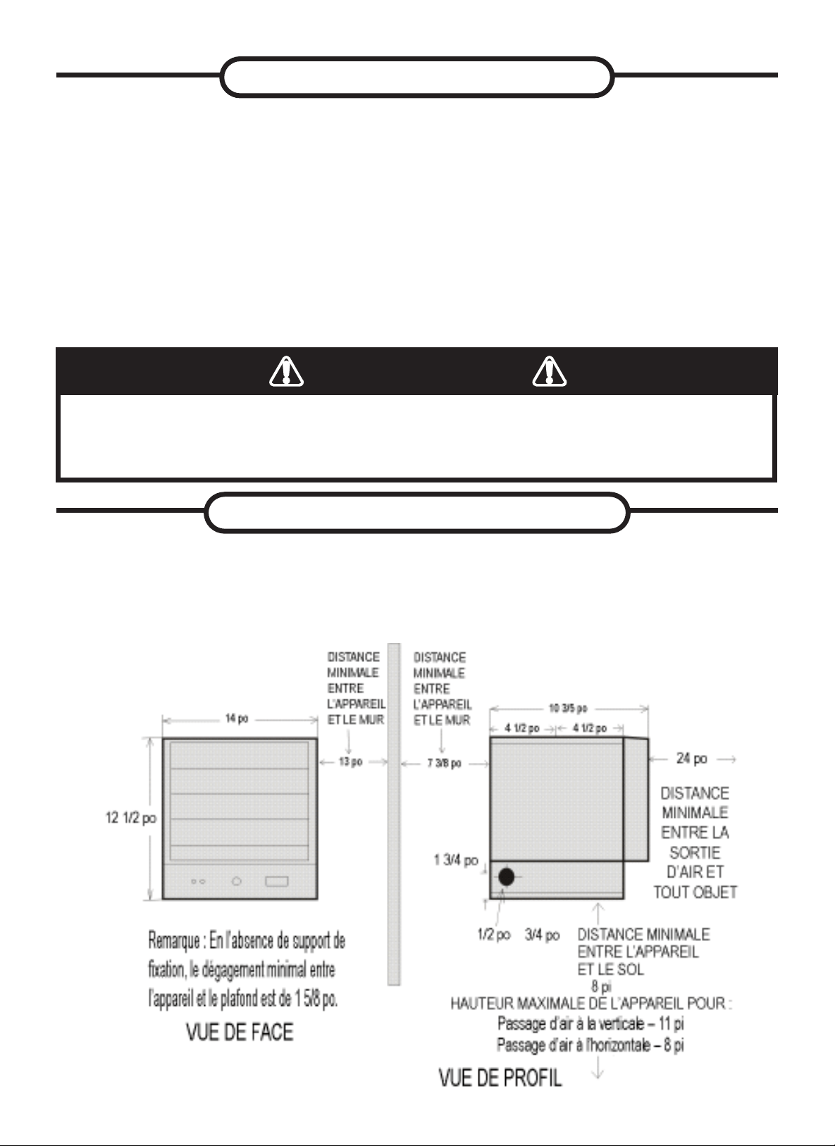
44
Figure 2
Installez le radiateur à l’écart des zones de circulation et maintenez le dégagement minimal
décrit à la gure 2. Le passage d’air ne doit pas être obstrué par des colonnes ou des
machines, et l’air doit longer les murs plutôt qu’être poussé directement sur ces derniers.
Lorsque plusieurs radiateurs sont utilisés, ils doivent être disposés de façon à créer un
passage d’air continu avec les autres radiateurs an de mieux faire circuler l’air chaud,
comme illustré à la gure 3.
EMPLACEMENT DU RADIATEUR
UNE INSTALLATION INCORRECTE OU LE NON-RESPECT DES PROCÉDURES DÉCRITES
DANS LE PRÉSENT GUIDE D’INSTRUCTION PEUT CAUSER DES DÉCHARGES
ÉLECTRIQUES GRAVES.
AVERTISSEMENT
INFORMATION DE SÉCURITÉ
6. Toute l’alimentation électrique doit être coupée et le panneau électrique principal doit être
verrouillé avant d’exécuter une inspection, un nettoyage ou un entretien du radiateur.
Cette précaution permet d’éviter des décharges électriques graves.
7. Ce radiateur n’est pas adapté aux endroits dangereux tels que dénis par la National Fire
Protection Association (NFPA) aux États-Unis. Le radiateur contient des pièces chaudes
et des pièces produisant des arcs électriques ou des étincelles. N’utilisez pas cet appareil
à des endroits où de l’essence, de la peinture ou des liquides inammables sont utilisés
ou entreposés.
8. Ce radiateur n’est pas adapté aux environnements agressifs comme les serres à l’eau
de mer et les entrepôts de produits chimiques.
9. Le radiateur doit être installé à au moins 8 pieds du sol. Pour des dégagements
spéciques, voir la gure 2.

45
Pièce Description Quantité
A Chauffe-garage 1
B Support de montage 1
C Télécommande infrarouge 1
D Vis 6
E Rondelle 12
PRE-INSTALLATION
Figure 3
EMPLACEMENT DU RADIATEUR
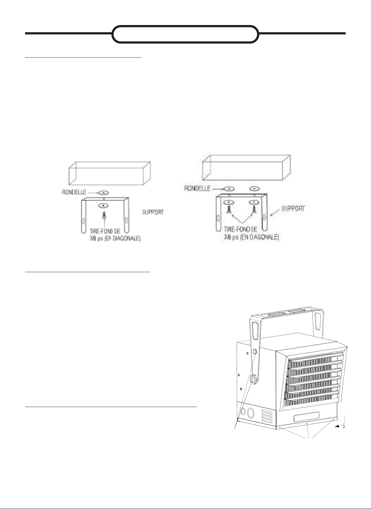
46
Plafond en bois
Plafond en bois
Figure 4a. Installation avec une vis Figure 4b. Installation avec deux vis
INSTALLATION DU SUPPORT
Consultez les gures 4a et 4b.
1. Repérez une poutre en bois dans la solive de plafond. Si vous ne trouvez aucune
poutre en bois, vous devez installer un morceau de bois au plafond an de xer
solidement le radiateur.
2. Pour retirer le support de xation du radiateur, desserrez les vis à l’aide d’une clé
et glissez la poignée sur les têtes de vis.
3. Glissez une rondelle sur les vis avant de les insérer dans les trous du support de
xation, puis vissez-les solidement dans la solive de plafond.
REMARQUE: Si vous prévoyez pivoter le radiateur vers la gauche ou la droite, il est
recommandé d’ajouter des rondelles de chaque côté du support. Un tire-fond plus long
peut être nécessaire pour xer correctement le radiateur. Voir la gure 4a.
INSTALLATION DU RADIATEUR
AJUSTEMENT DE LA DIRECTION DE L’AIR
1. Fixez le radiateur au support de xation.
2. Soulevez le radiateur pour l’aligner danas le
support de xation.
3. Alignez les vis du support avec les encoches
en trou de serrure du support de xation.
4. Serrez les vis du support avec une clé pour
que l’appareil soit solidement suspendu à
l’horizontale ou à la verticale.
5. L’appareil de chauffage peut être monté avec
différents angles indiqués dans le dessin
à la page 47 tant que vous maintenez le
dégagement approprié indiqué à la page 44.
Figure 5
1. Si le radiateur a été xé avec un seul tire-fond,
comme illustré à la gure 4a, il est possible
de le tourner horizontalement au besoin. Par
contre, s’il a été installé avec deux tire-fonds,
il ne peut être tourné de cette manière.
2. Pour pivoter le radiateur verticalement,
dévissez les vis du support (voir la gure 5).
INSTALLATION
UTILISER LES TROUS
DE MONTAGE SUPÉRIE
SI LE RADIATEUR SERA
INCLINÉ VERS LE BAS
RETIRER LA VIS POUR OUVRIR LA PORTE
DESSERREZ LES BOUTONS
ET SÉLECTIONNEZ LE TROU
DE MONTAGE EN FONCTION
DE L’ANGLE DE CHAUFFAGE
SOUHAITÉ. REPORTEZ-VOUS
AU SCHÉMA À LA PAGE 47.
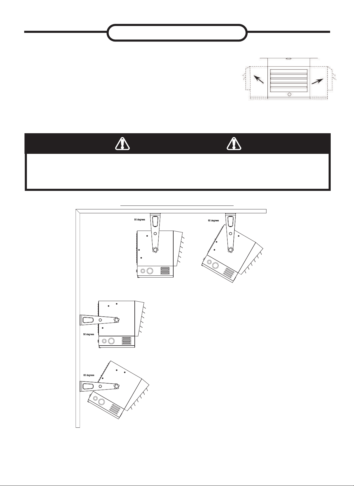
47
DIVERS ANGLES VERTICAUX
3.
Réglez la position des persiennes selon vos besoins
(voir la gure 6).
REMARQUE : Les persiennes sont conçues pour ne pas
pouvoir se fermer complètement. N’essayez pas de forcer
leur fermeture : vous pourriez endommager le radiateur.
INSTALLATION
Figure 6
POUR PRÉVENIR LES RISQUES DE DÉCHARGE ÉLECTRIQUE, ÉTEIGNEZ LE RADIATEUR
ET COUPEZ L’ALIMENTATION AU PANNEAU ÉLECTRIQUE AVANT D’ENTREPRENDRE UN
RÉGLAGE DE LA SORTIE DE CHALEUR.
AVERTISSEMENT
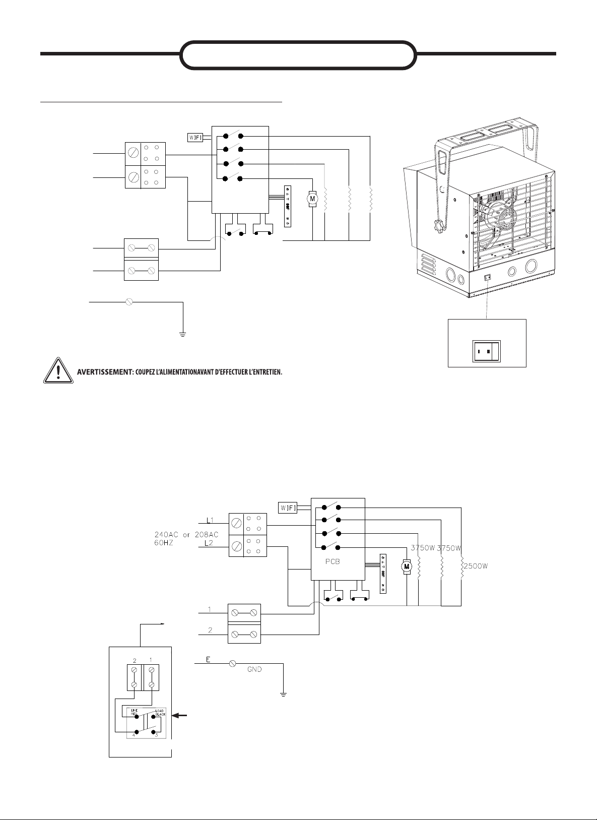
GND
E
L1
L2
1
2
240AC or 208AC
60HZ
External
thermostat
PCB
Selected
switch
2500W
3750W
3750W
48
BRANCHEMENT DE L’ALIMENTATION
INSTALLATION
Interrupteur de sélection
(thermostat du radiateur, thermostat externe)
Thermostat du
radiateur
Thermostat
externe
Thermostat
externe
Thermostat
externe
Gare terminus
Thermostat externe
Interrupteur de
sélection
Si vous désirez utiliser un thermostat externe pour commander le
fonctionnement du radiateur, veuillez porter attention aux points suivants :
1. Assurez-vous que le bouton du thermostat du radiateur est tourné au
maximum en sens horaire.
2. Connectez le l conformément au schéma de câblage ci-dessous.
REMARQUE : Lorsque vous
utilisez le thermostat DGT-240,
vous devez mettre « Load Black »
sur « 3 » sur le thermostat.
Interrupteur de
sélection
49
3. Connectez les ls au bloc d’alimentation à la base du radiateur (voir la gure 7).
4. Allumez l’alimentation au panneau électrique principal.
REMARQUE : Tout le câblage doit être effectué par un électricien certié et se
conformer aux codes régissant l’électricité à l’échelle locale et nationale. Certains
usages peuvent nécessiter des conduits de câbles. Voir la gure 6. Consultez
les codes locaux régissant l’électricité. Si vous faites passer le câblage dans un
conduit de câbles et que vous désirez pouvoir tourner le radiateur, assurez-vous de
disposer d’un conduit exible sufsamment long.
INSTALLATION
HAUTE TEMPÉRATURE – RISQUE D’INCENDIE. GARDEZ LES MATIÈRES INFLAMMABLES
COMME LES MEUBLES, LES OREILLERS, LES DRAPS, LE PAPIER, LES VÊTEMENTS,
CORDONS ÉLECTRIQUE ET LES RIDEAUX À AU MOINS 0,9 M (3 PI) DE L’AVANT ET DU
DESSUS DU RADIATEUR ET À BONNE DISTANCE DES CÔTÉS ET DE L’ARRIÈRE DE CELUI-CI.
POUR RÉDUIRE LES RISQUES D’INCENDIE, NE STOCKEZ PAS ET N’UTILISEZ PAS
D’ESSENCE OU D’AUTRES VAPEURS ET LIQUIDES INFLAMMABLES À PROXIMITÉ DE
L’APPAREIL DE CHAUFFAGE.
AVERTISSEMENT
AVERTISSEMENT
1. Retirez la vis de l’avant du radiateur pour connecter l’alimentation.
2. Installez les connecteurs de câbles sur l’appareil (voir la gure 7). Sélectionnez
le l d’alimentation électrique pour vous conformer aux codes électriques locaux et
nationaux en utilisant la cote de chauffage indiquée sur l’étiquette signalétique.
BRANCHEMENT DE L’ALIMENTATION
3. Le régulateur de température externe (thermostat externe) : un thermostat
certié doit être utilisé.
4. Les ls de connexion du thermostat externe doivent avoir un calibre d’au
moins 14 AWG.
PROTECTION DE L’ÉLÉMENT CHAUFFANT
Lors du démarrage de l’appareil de chauffage, en tournant lentement la commande
de température dans le sens horaire vers le réglage thermique souhaité, le ventilateur
démarre d’abord et ensuite l’élément chauffant. Pour éteindre le radiateur, tournez
lentement le bouton de réglage de température en sens antihoraire.
CYCLE DE REFROIDISSEMENT
Le cycle de refroidissement peut prendre jusqu’à 5 minutes et peut s’allumer et à
s’éteindre au besoin pour bien refroidir.
CET APPAREIL DOIT ÊTRE MIS À LA TERRE.
L’APPAREIL DOIT ÊTRE CONNECTÉ À UN CIRCUIT OU À UN DISPOSITIF DE PROTECTION
DE COURANT AVANT D’ÊTRE CONNECTÉ À L’ALIMENTATION !
AVERTISSEMENT
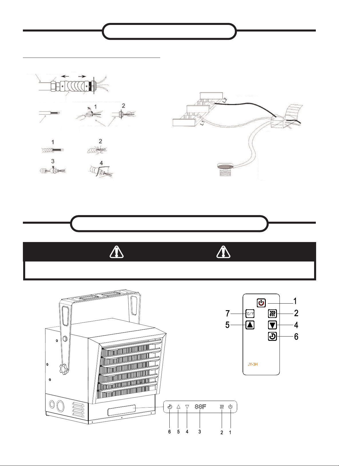
50
Connecteurs, câbles et quincaillerie
utilisés pour brancher le radiateur
Figure 7
Connecteur de conduit
de câbles
3pi
Conduit
de câbles
Conduit exible
Câble exible
non métallique
Connecteur de câble
exible non métallique
Connecteur de conduit exible
BLANC
NOIR
VERT
(ou cuivre nu)
BRANCHEMENT DE L’ALIMENTATION
INSTALLATION
LE RADIATEUR DOIT ÊTRE CORRECTEMENT INSTALLÉ AVANT D’ÊTRE MIS EN FONCTION.
AVERTISSEMENT
INSTRUCTIONS DE FONCTIONNEMENT
Panneau de commande
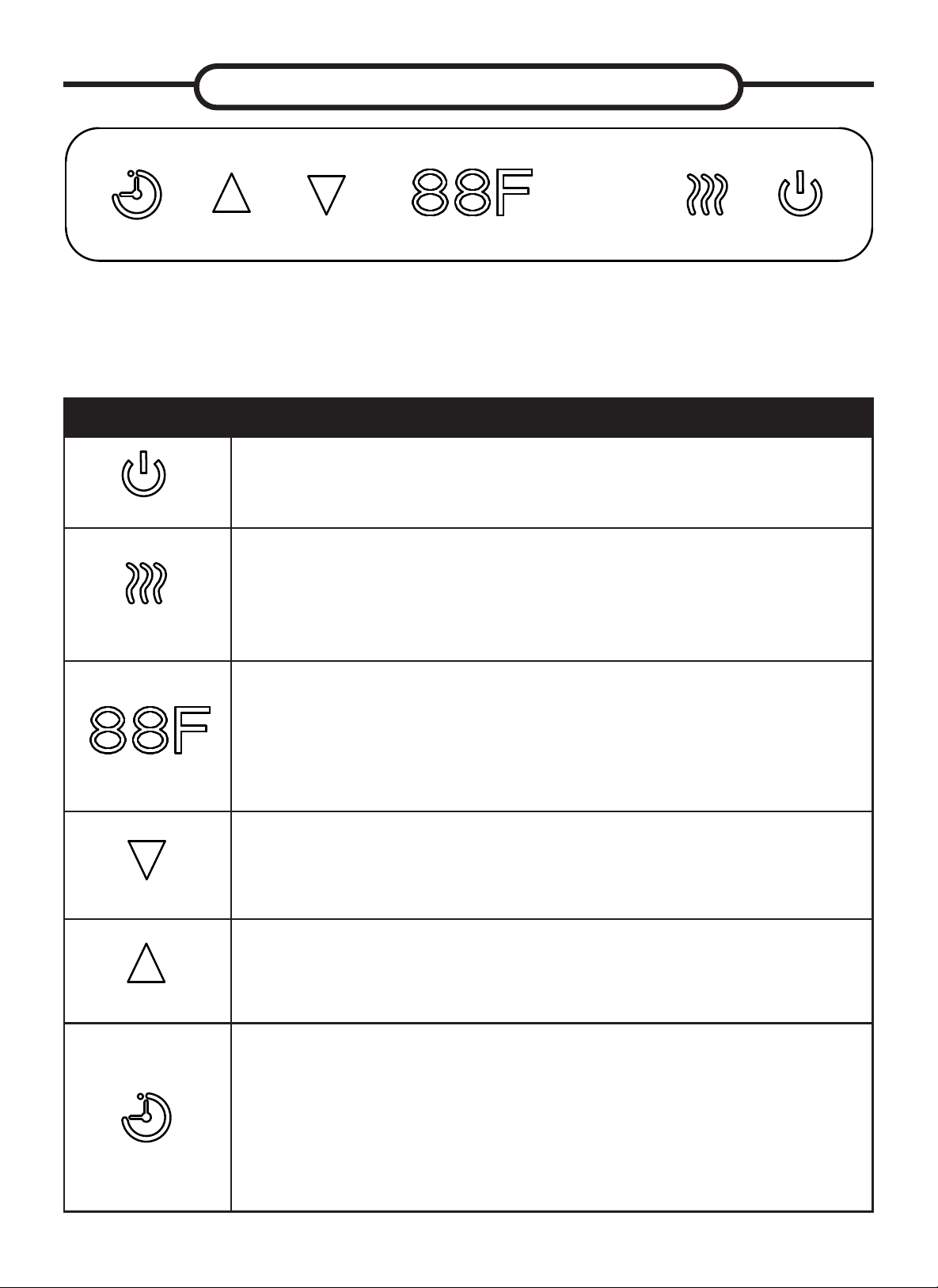
51
INSTRUCTIONS DE FONCTIONNEMENT
Vériez que la grille de sortie du radiateur de garage n’est pas couverte ni obstruée, et assurez-vous
que l’alimentation vers l’appareil est allumée.
Le radiateur de garage peut être contrôlé de trois façons :
• Utilisation du panneau de commande tactile, situé à l’avant du chauffage de garage, sous les plaques
de guidage d’air.
• Utilisation de la télécommande multifonction.
• Utilisation de l’application sur votre appareil mobile.
Icône Ce que le radiateur va faire :
Figure 1
Bouton d’alimentation principal :
Ce bouton fournit l’alimentation à toutes les fonctions du radiateur
de garage. Il doit être activé pour que le radiateur puisse
fonctionner.
Figure 2
Bouton de contrôle du radiateur :
Ce bouton ajuste les 4 niveaux de chauffage: AH, H, L, FA: AU
(le chauffage s’ajustera entre bas (7500 W afche « L ») et haut
(10000 W afche « H ») en fonction de la température ambiante);
H (haut—10000 W afche « H »); L (Bas—7500 W afche « L »);
FA (ventilateur seulement).
Figure 3
Afchage de température/minuterie :
Cet afchage DEL afche le réglage des fonctions de température
et de minuterie. Quand l’une de ces fonctions est activée,
l’afchage indique le réglage pendant cinq secondes puis s’éteint.
Tout changement au réglage de la température ou de la minuterie
réactivera l’afchage, qui s’éteint de nouveau après cinq secondes.
Figure 4
Bouton de commande BAS :
Ce bouton réduit la température ou le temps, ajustant la plage de
température de 10 °C à 35 °C (50 °F à 95 °F), par intervalles de 1
°F (/1 °C).
Figure 5
Bouton de commande HAUT :
Ce bouton augmente la température ou le temps, ajustant la plage
de température de 10 °C à 35 °C (50 °F à 95 °F), par intervalles de
1 °F (/1 °C).
Figure 6
Bouton de minuterie :
Ce bouton met en marche et arrête la minuterie qui a 8 réglages
de temps allant de 1 heure à 8 heures. Quand la minuterie est
mise en marche, le réglage le plus court est activé (1 heure).
Chaque fois que vous appuyez sur le bouton de minuterie, le
temps augmente d’une heure, jusqu’au réglage le plus long
(8 heures). Une fois que le temps réglé est écoulé, toutes les
fonctions du radiateur de garage s’éteignent automatiquement.
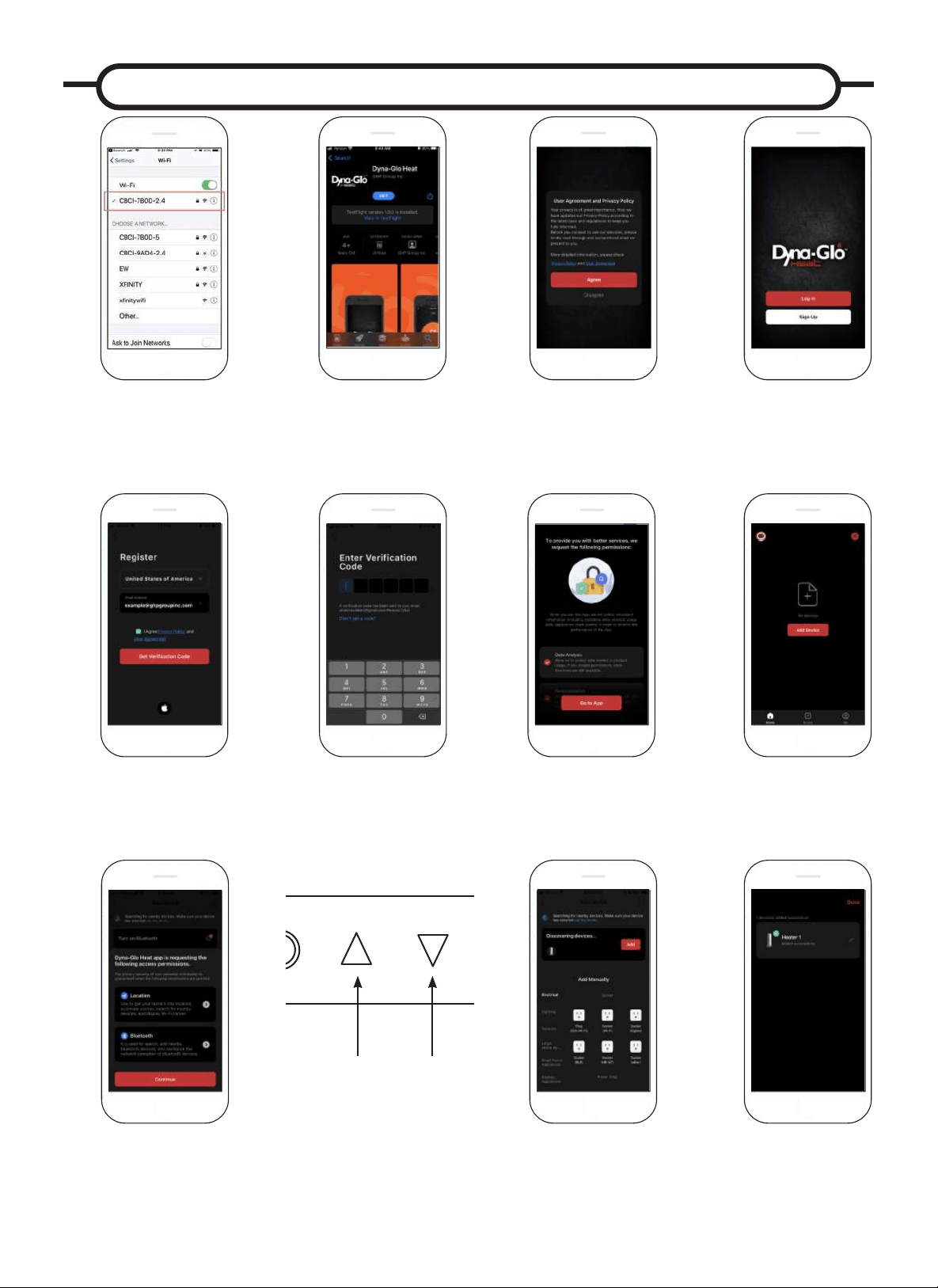
52
INSTRUCTIONS D’UTILISATION DE L’APPLICATION MOBILE
Reliez votre téléphone à un
réseau WiFi de 2,4 GHz.
*Pour certains routeurs bi-bande, vous
devrez peut-être créer manuellement
un réseau dédié à 2,4 GHz.
Pendant que le
chauffage est branché
et allumé, appuyez et
maintenez le symbole
des èches haut et
bas sur l’écran de
contrôle pendant 5
sec. Vous devriez
entendre un bip.
Téléchargez l’application
Dyna Glo Heater sur
Google Play ou sur iOS
App Store.
Cliquez sur « D’accord »
pour accepter l’accord de
l’utilisateur et la politique de
condentialité.
Autorisez Dyna-Glo à se
connecter à votre réseau
local et à fournir une analyse
et une personnalisation des
données.
Créez un compte Dyna-Glo
ou connectez-vous à un
compte existant.
Sur l’écran d’accueil,
cliquez sur « Ajouter un
appareil ».
Création d’un nouveau compte:
Saisissez votre adresse électronique et appuyez
sur la case pour accepter l’accord de l’utilisateur
et la politique de condentialité. Un code de
vérication sera envoyé à l’adresse électronique
fournie.
Autorisez l’application
Dyna-Glo Heat à accéder à
la localisation de l’appareil
et au Bluetooth.
Entrez le code de
vérication.
Après l’étape 7, une fenêtre
contextuelle apparaîtra sur votre
téléphone qui recherche l’appareil à
jumeler. Une fois que ceci apparaît,
cliquez sur Ajouter.
Votre écran devrait ressembler
à ceci : S’il afche des
notications d’erreur, consultez
notre guide de dépannage
WiFi en ligne.
4
6
Enjoy your new Heat
6WRUP:LÀ+HDWHU
If you have any ques-
tions or concerns, feel
free to contact us at:
435-752-6611
1
1
4
6
Enjoy your new Heat
6WRUP:LÀ+HDWHU
If you have any ques-
tions or concerns, feel
free to contact us at:
435-752-6611
8
8
4
6
Enjoy your new Heat
6WRUP:LÀ+HDWHU
If you have any ques-
tions or concerns, feel
free to contact us at:
435-752-6611
5
9
4
6
Enjoy your new Heat
6WRUP:LÀ+HDWHU
If you have any ques-
tions or concerns, feel
free to contact us at:
435-752-6611
4
6
Enjoy your new Heat
6WRUP:LÀ+HDWHU
If you have any ques-
tions or concerns, feel
free to contact us at:
435-752-6611
4
6
Enjoy your new Heat
6WRUP:LÀ+HDWHU
If you have any ques-
tions or concerns, feel
free to contact us at:
435-752-6611
4
6
Enjoy your new Heat
6WRUP:LÀ+HDWHU
If you have any ques-
tions or concerns, feel
free to contact us at:
435-752-6611
4
6
Enjoy your new Heat
6WRUP:LÀ+HDWHU
If you have any ques-
tions or concerns, feel
free to contact us at:
435-752-6611
4
6
Enjoy your new Heat
6WRUP:LÀ+HDWHU
If you have any ques-
tions or concerns, feel
free to contact us at:
435-752-6611
4
6
Enjoy your new Heat
6WRUP:LÀ+HDWHU
If you have any ques-
tions or concerns, feel
free to contact us at:
435-752-6611
4
6
Enjoy your new Heat
6WRUP:LÀ+HDWHU
If you have any ques-
tions or concerns, feel
free to contact us at:
435-752-6611
2 2
2
2
22
2
2
2 3
4c
4
54a
6
4b
7
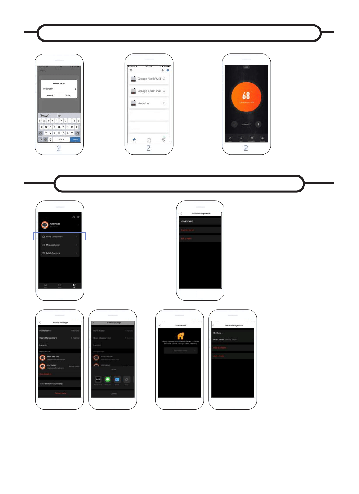
53
CONNEXION DE PLUSIEURS APPAREILS À L’APPAREIL DE CHAUFFAGE
Pour connecter plusieurs
appareils, accédez à l’onglet
Moi et cliquez sur Gestion de
la maison.
À partir de là, sélectionnez Créer une
maison où vous pouvez entrer un Nom de
maison et dénir un emplacement si vous
le souhaitez. Après cela, vous devriez voir
le Nom de la maison en haut de la page.
Sélectionnez votre Nom de maison.
Cela vous mènera à une page des
Paramètres d’accueil où vous pourrez
sélectionner Ajouter un membre pour
connecter un nouvel appareil. Vous
serez ensuite invité à sélectionner
comment envoyer le lien d’invitation au
membre que vous souhaitez ajouter.
En règle générale, le message texte est le moyen le plus simple d’envoyer
le code, mais il existe plusieurs options parmi lesquelles choisir. Pour les
invitations par message texte, vous recevrez un code à 6 chiffres et vous
pourrez le saisir dans la page Gestion de la maison > Rejoindre la maison.
Si vous partagez via l’option Compte d’application, le destinataire recevra
un message dans le Centre de messages de l’application Dyna Glo Heat,
situé dans l’onglet Moi. Une fois que vous recevez ce message, vous
pouvez aller à la page Gestion de la maison et vous verrez le Nom de la
maison sur lequel cliquer pour rejoindre.
4
6
Enjoy your new Heat
6WRUP:LÀ+HDWHU
If you have any ques-
tions or concerns, feel
free to contact us at:
435-752-6611
1
4
6
Enjoy your new Heat
6WRUP:LÀ+HDWHU
If you have any ques-
tions or concerns, feel
free to contact us at:
435-752-6611
2
4
6
Enjoy your new Heat
6WRUP:LÀ+HDWHU
If you have any ques-
tions or concerns, feel
free to contact us at:
435-752-6611
2
4
6
Enjoy your new Heat
6WRUP:LÀ+HDWHU
If you have any ques-
tions or concerns, feel
free to contact us at:
435-752-6611
2
4
6
Enjoy your new Heat
6WRUP:LÀ+HDWHU
If you have any ques-
tions or concerns, feel
free to contact us at:
435-752-6611
2
4
6
Enjoy your new Heat
6WRUP:LÀ+HDWHU
If you have any ques-
tions or concerns, feel
free to contact us at:
435-752-6611
2
1 2
3 4
Vous pouvez
également
connecter
plusieurs
radiateurs
Dyna Glo
pour tous vos
besoins de
chauffage.
Maintenant, vous pouvez
contrôler votre appareil
de chauffage avec votre
téléphone de n’importe où!
Vous pouvez ajuster les
températures, régler les
minuteries, et rester au chaud
d’un claquement de doigt!
Pour utiliser l’application
mobile pour contrôler votre
appareil de chauffage, vous
devez être déconnecté du
thermostat externe en vous
assurant que l’interrupteur
à l’arrière de l’appareil est
réglé sur le réglage interne
du thermostat.
4
6
Enjoy your new Heat
6WRUP:LÀ+HDWHU
If you have any ques-
tions or concerns, feel
free to contact us at:
435-752-6611
1110
4
6
Enjoy your new Heat
6WRUP:LÀ+HDWHU
If you have any ques-
tions or concerns, feel
free to contact us at:
435-752-6611
12
Vous
pouvez
maintenant
renommer
votre
appareil de
chauffage
pour qu’il
corresponde
à la pièce
dans
laquelle il se
trouve.
4
6
Enjoy your new Heat
6WRUP:LÀ+HDWHU
If you have any ques-
tions or concerns, feel
free to contact us at:
435-752-6611
4
6
Enjoy your new Heat
6WRUP:LÀ+HDWHU
If you have any ques-
tions or concerns, feel
free to contact us at:
435-752-6611
INSTRUCTIONS D’UTILISATION DE L’APPLICATION MOBILE
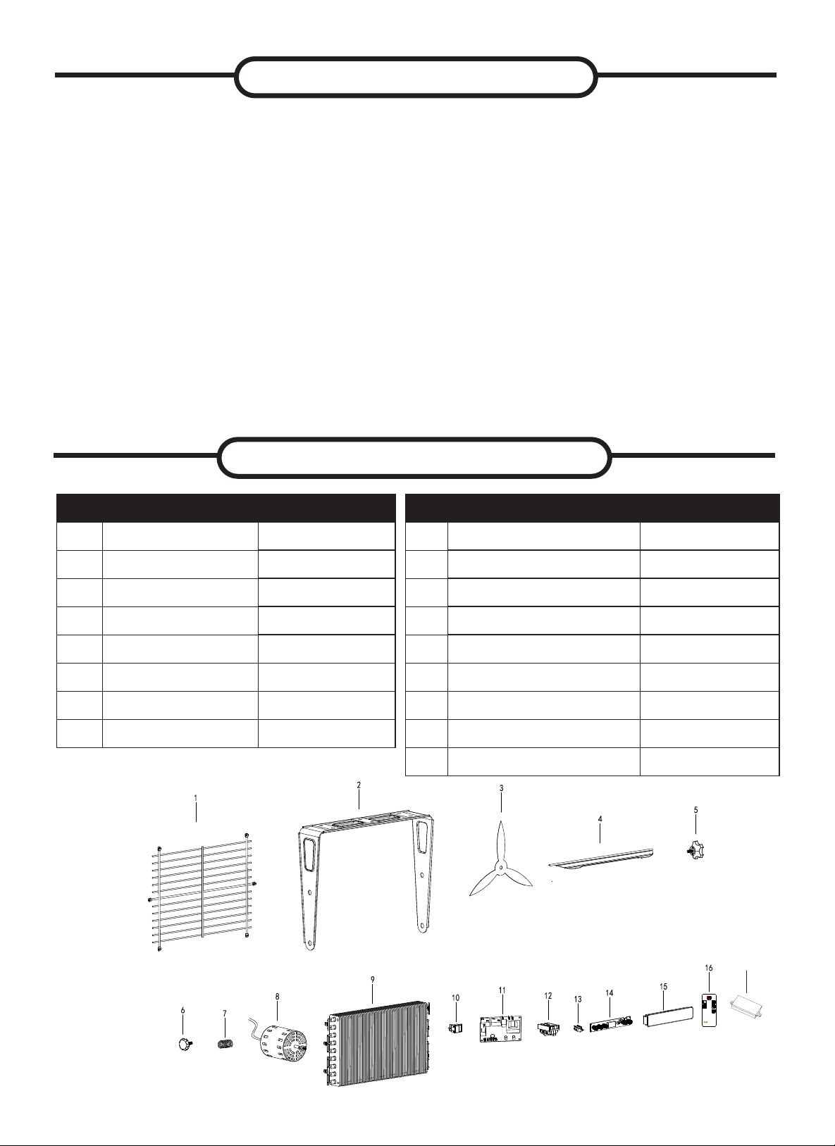
54
ENTRETIEN ET NETTOYAGE
1. Avant de nettoyer le radiateur, veillez à couper l’alimentation sur le panneau à
disjoncteurs et à laisser refroidir les éléments chauffants.
2. Pour maintenir l’apparence externe du radiateur, il suft de l’épousseter à sec
à l’occasion. Vous pouvez proter de la période estivale ou de tout autre
moment où le radiateur n’est pas utilisé et est complètement refroidi pour
passer un linge humide sur l’appareil.
3. N’utilisez pas de nettoyants en poudre abrasifs ni de nettoyants pour
meubles. N’utilisez pas de produits chimiques ou abrasifs, de tampon
à récurer en métal, ni de quoi que ce soit qui pourrait abîmer la surface de
l’appareil.
4. Durant l’été ou à tout autre moment où le radiateur n’est pas utilisé,
débranchez l’appareil. Rangez l’appareil dans un endroit frais et sec.
5. Toutes les autres tâches d’entretien doivent être effectuées par un technicien
qualié. N’essayez pas de réparer vous-même le radiateur.
REMARQUE : Le moteur est lubrié en permanence et aucune lubrication
supplémentaire n’est nécessaire.
PIÈCES DE REMPLACEMENT
Pièce Description No. de pièce
1
Grille arrière
EG10000DH001AC
2
Plaque de suspension
EG10000DH002AC
3
Pale de ventilateur
EG10000DH003AC
4
Plaque de guidage d’air
EG10000DH004AC
5
Grande poignée
EG5000005AC
6
Petite poignée
EG5000006AC
7
Ressort
EG5000007AC
8
Moteur
EG10000DH005AC
Pièce Description No. de pièce
9
Chauffage
EG10000DH006AC
10 Interrupteur de sélection
EG5000011AC
11 Tableau principal EG7500WB001AC
12 Bloc terminal EG5000014AC
13
Coupure de température EG5000017AC
14 Carte de circuit imprimé EG10000WB002AC
15 Boîtier de commande EG7500DH003AC
16 Télécommande infrarouge EG7500DH004AC
17
Module Wi-Fi et Bluetooth
EG7500WB005AC
17
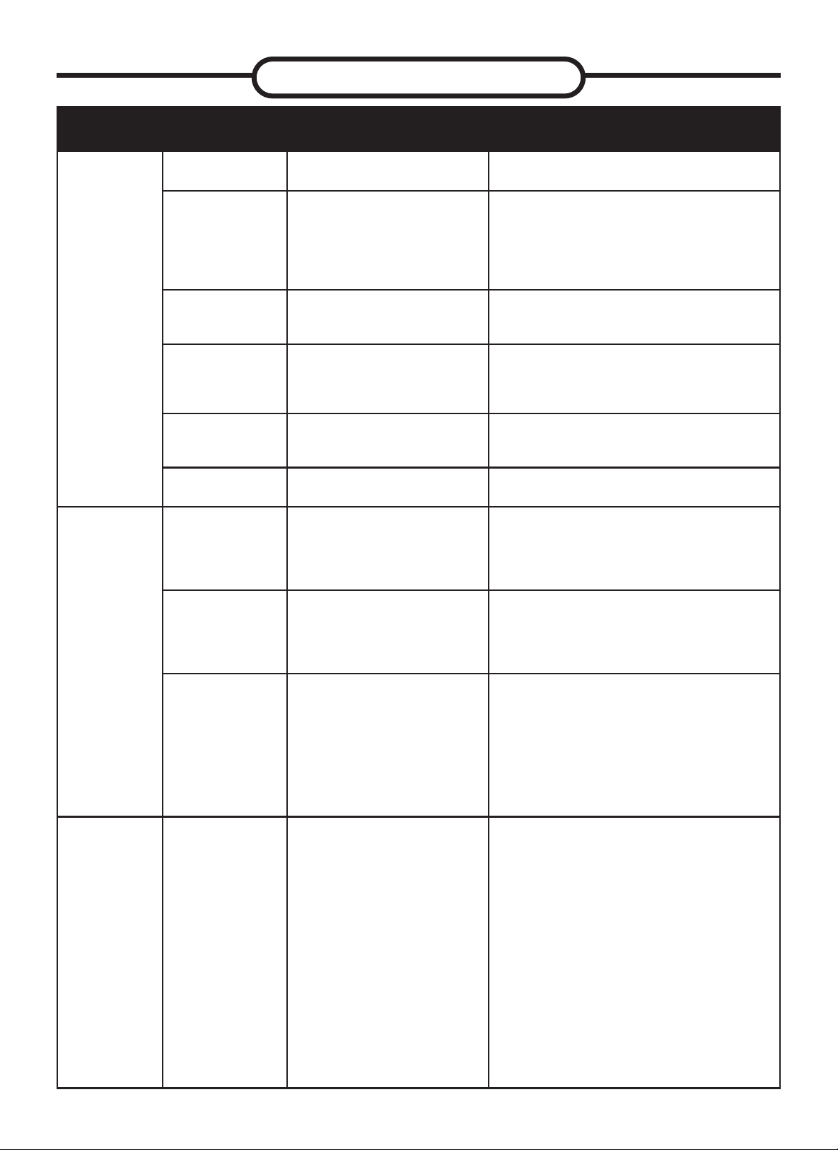
DÉPANNAGE
55
PROBLÈME
CODE
AFFICHÉ
CAUSE MESURES CORRECTIVES
L’appareil ne
chauffe pas
« EE »
s’afche
Le capteur du thermostat
est cassé ou débranché.
Veuillez appeler le service clientèle.
« EF »
s’afche
La protection anti-surchauffe
est activée.
Inspectez le radiateur de garage et vériez
que les entrées et sorties d’air ne sont pas
bouchées, car cela pourrait causer une sur-
chauffe. Éteignez le disjoncteur du radiateur
pendant 30 minutes et laissez l'appareil
refroidir. Rallumez l’appareil.
« LOC »
s’afche
Le radiateur est en mode
VERROUILLÉ.
Maintenez le bouton d’alimentation enfoncé
pendant 10 secondes pour déverrouiller la
fonction de chauffage.
« FA »
s’afche et le
radiateur soufe
de l’air froid
Le radiateur est réglé sur
mode VENTILATEUR.
Changez le réglage et passez en mode de
chauffage « AUT »
Le radiateur ne
démarre pas
La température ambiante a
déjà atteint la température
réglée sur le thermostat.
Réglez la température pour que la tempéra-
ture du thermostat soit supérieure à la
température ambiante actuelle.
Le radiateur ne
démarre pas
Le disjoncteur s’est dé-
clenché.
Réarmez le disjoncteur au panneau de
fusibles et redémarrez le radiateur.
Le radiateur
de garage
émet une
odeur de brûlé
Lors de la fabrication du
produit, de la poussière et/ou
de l’huile se sont accumulées
sur les bobines de chauffage.
Assurez-vous que la pièce est bien ventilée.
Mettez le radiateur de garage en marche
jusqu’à ce que l’odeur soit dissipée.
Vériez qu’il n’y a pas de
matériau combustible à moins
de 0,9 mètres (3 pieds) du
radiateur de garage.
Enlevez le matériau combustible autour du
radiateur de garage.
Ce radiateur doit être monté
à une hauteur minimum de
8 pieds du sol. Pour voir des
dégagements spéciques,
veuillez consulter la section
« EMPLACEMENT DU
RADIATEUR » dans le mode
d’emploi.
Déplacez le radiateur de garage
de sorte qu’il y ait assez de place
entre le radiateur et le mur et le
plancher adjacents.
L’appareil
n’arrêtera pas
de fonctionner
après l’avoir
éteint.
L’appareil de chauffage
a un cycle de refroid-
issement intégré pour
protéger l’élément
chauffant.
Attendez que le capteur de température
éteigne le ventilateur. Cela peut prendre
jusqu’à 5 à 10 minutes en fonction de la
température de l’environnement. L’appar-
eil peut s’allumer et s’éteindre plusieurs
fois avant de s’éteindre complètement.
Exemple :
En marche pendant 15 secondes, re-
froidissement pendant 10 s; En marche
pendant plus de 15 seconds, refroidisse-
ment pendant 90 s.

NOTES DE PRODUIT

GARANTIE
GARANTIE LIMITÉE :
Cette garantie limitée n’est offerte qu’à l’acheteur initial de cet appareil à air pulsé/appareil à convection/radiateur et assure qu’il sera exempt de défauts de
matériaux et de fabrication pour une période d’un (1) an à partir de la date d’achat (seule la buse en cuivre du brûleur bénécie d’une garantie à vie). À sa discrétion,
GHP Group, Inc. pourra fournir des pièces de rechange ou remplacer ou réparer l’unité lorsque celle-ci est bien retournée chez le détaillant où elle a été achetée ou
dans l’un de nos centres de service, tel qu’exigé par GHP Group, Inc, dans un délai d’un (1) an suivant la date d’achat. (Les frais d’expédition, de main-d’œuvre et
autres sont la responsabilité de l’acheteur.)
RESPONSABILITÉS DU PROPRIÉTAIRE :
Cet appareil de chauffage doit être utilisé conformément aux instructions écrites qui l’accompagnent. Cette garantie ne permet pas au propriétaire de négliger
l’entretien requis du radiateur conformément aux instructions écrites qui l’accompagnent. Une facture de vente, un chèque payé ou un historique de paiement sont
nécessaires à la vérication de la date d’achat et de la période de couverture. La boîte d’origine doit être conservée en cas de retour du produit sous garantie.
LA GARANTIE NE COUVRE PAS :
1. Les dommages causés par l’utilisation d’un mauvais combustible.
2. Les dommages causés par une mauvaise utilisation ou par une utilisation contraire au guide d’utilisation et aux consignes de sécurité.
3. Les dommages causés par un manque d’entretien régulier.
4. Les fusibles.
5. L’utilisation de pièces ou d’accessoires non standards.
6. Les dommages causés lors d’un déplacement. Il est de la responsabilité du propriétaire d’acquitter les frais de transport des pièces ou des radiateurs sous
garantie en direction ou en provenance de l’usine.
La présente garantie n’implique aucune responsabilité pour les dommages indirects résultant de l’utilisation conforme, d’une mauvaise utilisation ou du manque
d’entretien régulier de cet appareil de chauffage. En cas de bris qui résulteraient d’un manque d’entretien, des frais de nettoyage et de remplacement de pièces
pourraient être facturés. La présente garantie s’applique uniquement aux réclamations concernant des défauts de fabrication ou de matériaux. NE PAS EFFECTUER
L’ENTRETIEN GÉNÉRAL RÉGULIER (Y COMPRIS LE NETTOYAGE) ENTRAÎNERA L’ANNULATION DE CETTE GARANTIE.
CETTE GARANTIE LIMITÉE DONNÉE À L’ACHETEUR REMPLACE TOUTE GARANTIE, EXPRESSE OU IMPLICITE, Y COMPRIS, MAIS SANS S’Y LIMITER, LES
GARANTIES DE QUALITÉ MARCHANDE ET D’ADÉQUATION DANS UN BUT PARTICULIER. LE RECOURS OFFERT PAR CETTE GARANTIE EST EXCLUSIF ET
REMPLACE TOUS LES AUTRES RECOURS. GHP GROUP, INC. NE SERA EN AUCUN CAS TENU RESPONSABLE DE TOUT DOMMAGE CONSÉCUTIF OU INDIRECT.
Les lois en vigueur dans certains États, provinces ou territoires n’autorisent pas la limitation de la durée d’une garantie implicite et, par conséquent, les limitations
énoncées ci-dessus pourraient ne pas s’appliquer à vous. Les lois en vigueur dans certains États, provinces ou territoires n’autorisent pas l’exclusion ou la limitation
des dommages consécutifs ou indirects et, par conséquent, la clause de limitation ou d’exclusion énoncée ci-dessus pourrait ne pas s’appliquer à vous.
LES DEMANDES SERONT TRAITÉES COMME SUIT :
1. Communiquez avec votre détaillant an de lui expliquer votre problème.
2. Si le détaillant n’est pas en mesure de régler votre problème, communiquez avec notre service à la clientèle avec votre preuve d’achat en main, puis
mentionnez le modèle de votre radiateur et décrivez votre problème.
3. Un représentant communiquera ensuite avec vous. NE RENVOYEZ PAS LE RADIATEUR À GHP GROUP, INC. à moins que l’un de nos représentants ne vous
le demande. La présente garantie vous accorde des droits spéciques reconnus par la loi et vous bénéciez peut-être d’autres droits, qui peuvent varier selon
l’État, la province ou le territoire.
POUR ENREGISTRER LA GARANTIE DE VOTRE RADIATEUR, REMPLISSEZ ET POSTEZ CETTE CARTE
DANS LES 14 JOURS SUIVANT LA DATE D’ACHAT, OU ENREGISTREZ-LA EN LIGNE AU www.ghpgroupinc.com.
NOM : N
O
DE TÉLÉPHONE : ADRESSE ÉLECTRONIQUE :
ADRESSE : VILLE : ÉTAT : CODE POSTAL :
MODÈLE : N
O
DE SÉRIE : DATE D’ACHAT :
DISTRIBUTEUR CHEZ QUI L’ACHAT A ÉTÉ EFFECTUÉ : TYPE DE MAGASIN :
VILLE ET ÉTAT OÙ L’ACHAT A ÉTÉ EFFECTUÉ : VALEUR À L’ACHAT :
Merci de prendre une minute afi n de répondre aux questions qui suivent.
Vos réponses seront utilisées uniquement à des fi ns d’étude du marché et resteront confi dentielles.
Qui a été le principal instigateur de cet achat? Homme Femme 18-24 25-39 40-59 60 et plus
Quelle était la raison de l’achat?
Possédez-vous d’autres radiateurs portatifs? Oui Non Si oui, de quel type? De quelle marque?
Quel usage prévoyez-vous faire de votre nouveau radiateur? Chantier de construction Ferme Entrepôt/commercial Garage/annexe Autre
Comment avez-vous découvert ce radiateur? Étalage en magasin Annonce dans les journaux Annonce dans les magazines
Ami/proche Annonce à la télévision Commis en magasin Autre
Pourquoi avez-vous choisi ce radiateur? Style Taille/portabilité Prix Emballage Marque Autre
Êtes-vous : Propriétaire Locataire Recommanderiez-vous ce radiateur à un ami? Oui Non
Veuillez partager vos commentaires avec nous :
MERCI D’AVOIR REMPLI CE FORMULAIRE!
Vos renseignements resteront confi dentiels.
ENREGISTREMENT DE LA GARANTIE
CONSERVEZ CETTE CARTE!
Placez le
timbre ici
GHP Group, Inc.
6440W.HowardSt.
Niles, IL60714-3302 États-Unis
Tél.: 18774474768
www.ghpgroupinc.com
IMPORTANT: Nous vous invitons à remplir votre carte d’enregistrement de garantie dans
les quatorze(14)jours suivant la date de votre achat. Vous pouvez également enregistrer
votre garantie par Internet au www.ghpgroupinc.com. Veuillez entrer le numéro de série
complet. Veuillez conserver cette partie de la carte pour vos dossiers personnels.
GHP Group, Inc.
6440W.HowardSt.
Niles, IL60714-3302
GHP Group, Inc.
6440 W Howard St
Niles, IL 60714-3302
Tél. : 1 877 4474768
www.ghpgroupinc.com
GHP Group, Inc.
6440 W Howard St
Niles, IL 60714-3302