PLANNING GUIDE
48" PROFESSIONAL
COOKTOPS & BACKGUARDS
—
CPV2-485, CPV2-486GD, CPV2-486GL, CPV2-488,
BGCV2-1248, BGCV2-3048, BGCV2-3048H models

CONTENTS
48" Professional Cooktop
CPV2-485, CPV2-486GD, CPV2-486GL, CPV2-488
PAGE
in mm
Key Design Decisions 5 23
Ventilation Requirements 6 24
48" Professional Cooktop
CPV2-485
Product & Cavity Dimensions 7 25
Clearance Dimensions 8 26
Cavity Preparation 9 27
48" Professional Cooktop
CPV2-486GL
Product & Cavity Dimensions 10 28
Clearance Dimensions 11 29
Cavity Preparation 12 30
48" Professional Cooktop
CPV2-486GD
Product & Cavity Dimensions 13 31
Clearance Dimensions 14 32
Cavity Preparation 15 33

CONTENTS (continued)
48" Professional Cooktop
CPV2-488
PAGE
in mm
Product & Cavity Dimensions 16 34
Clearance Dimensions 17 35
Cavity Preparation 18 36
48" Professional Range Backguard
BGCV2-1248
Product Dimensions 19 37
48" Professional Range Backguard
BGCV2-3048
Product Dimensions 20 38
48" Professional Range Backguard
BGCV2-3048H
Product Dimensions 21 39

IMPERIAL
DATE: 24.04.2018
IMPORTANT: Throughout this guide, dimensions may vary by ±2mm (1/16'').
Read the installation manual for detailed information on installing the product.
For full installation instructions and specifications visit fisherpaykel.com
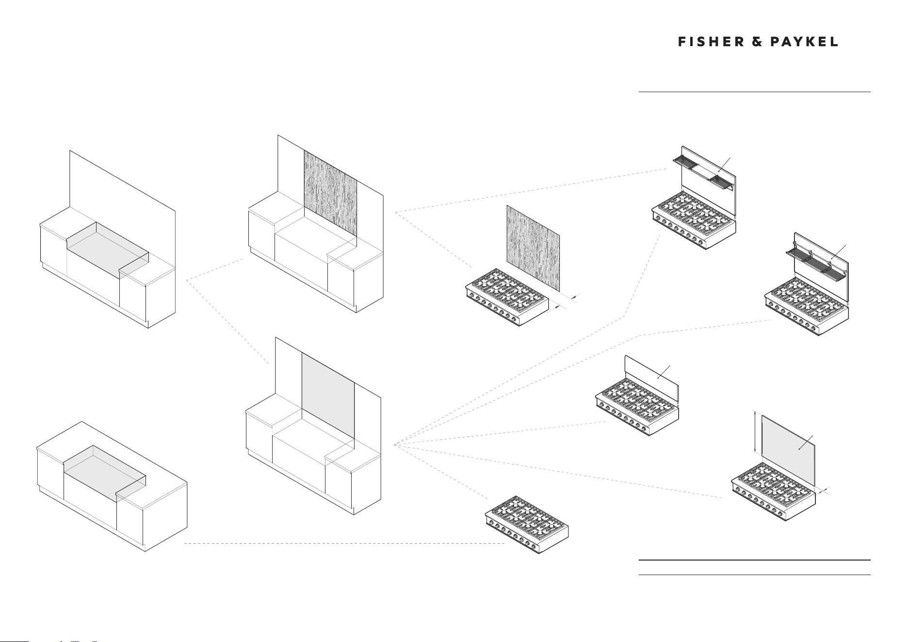
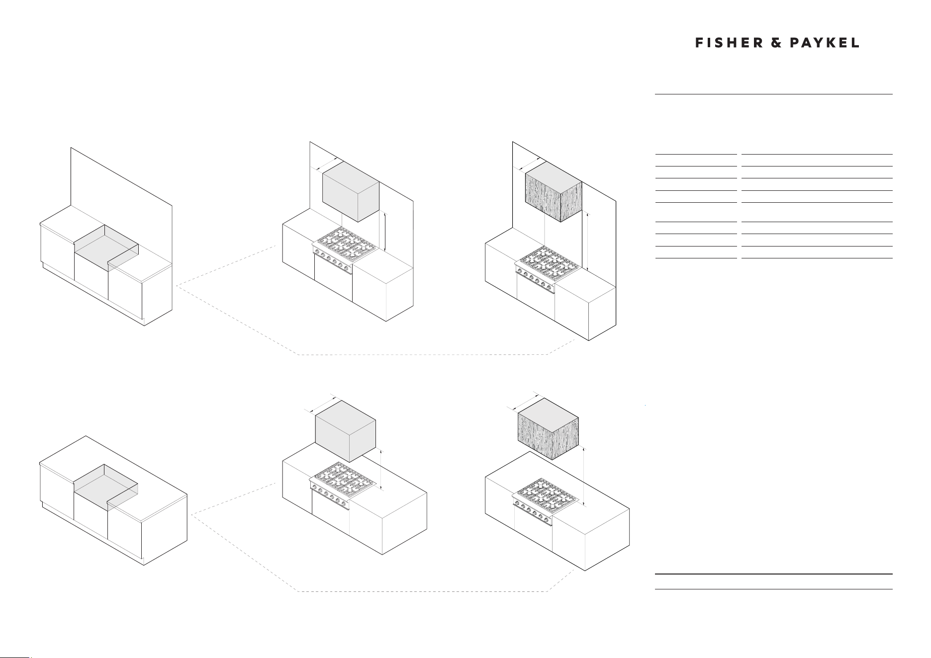
KEY DESIGN DECISIONS
48" Professional Range
INSTALL TYPE
1
WALL
ISLAND
REAR SURFACE
2
COMBUSTIBLE
NON COMBUSTIBLE
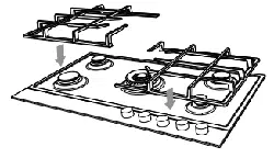
BACKGUARD OPTIONS
3
NO BACKGUARD
LOW BACKGUARD
LOW SHELF
HIGH BACKGUARD
HIGH SHELF
HIGH BACKGUARD
BGCV2-3048
BGCV2-3048H
BGRV2-1248
NO BACKGUARD
MIN 6"
CLEARANCE
CUSTOM FABRICATED* BACKGUARD
*Fabricated from non combustible materials only
CUSTOM
BACKGUARD*
MAX 15/16"
MIN 30"
Model no:
CPV2-485, CPV2-486GD,
CPV2-488, CPV2-486GL

DATE: 24.04.2018
IMPORTANT: Throughout this guide, dimensions may vary by ±2mm (1/16'').
Read the installation manual for detailed information on installing the product.
For full installation instructions and specifications visit fisherpaykel.com
VENTILATION REQUIREMENTS
48" Professional Gas Cooktop
MIN 36"
INSTALL TYPE
1
WALL
ISLAND
HOOD SURROUND MATERIAL
2
NON COMBUSTIBLE
23"
NON COMBUSTIBLE
MIN
30"
MAX
36"
MIN 30"
MAX 36"
30"
COMBUSTIBLE
COMBUSTIBLE
30"
MIN 36"
23"
Model no:
CPV2-485, CPV2-486GD,
CPV2-488, CPV2-486GL
Note: CPV2-366 illustrated but all dimensions apply to the above models
Specifications
Ventilation Unit
Wall Installation
Hood
23'' Deep x Unit Width
Blower
1200 CFM
Ventilation Unit
Island Installation
Hood
30'' Deep x Unit Width
Blower
1200 CFM
Note: A suitable hood must be installed above the cooktop.
The above indicates the minimum blower capacity recommended
for hood ventilation.
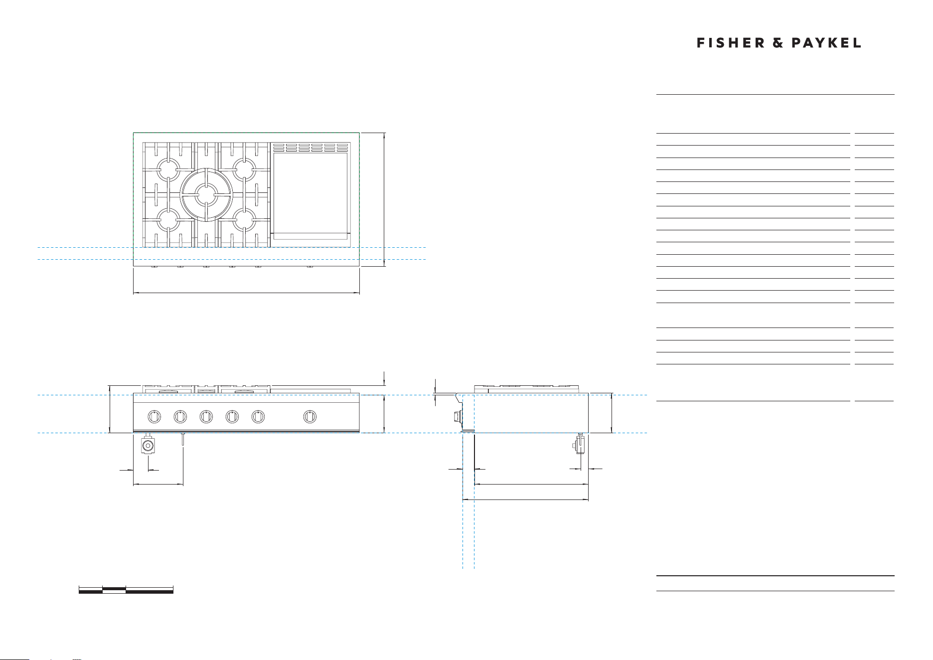
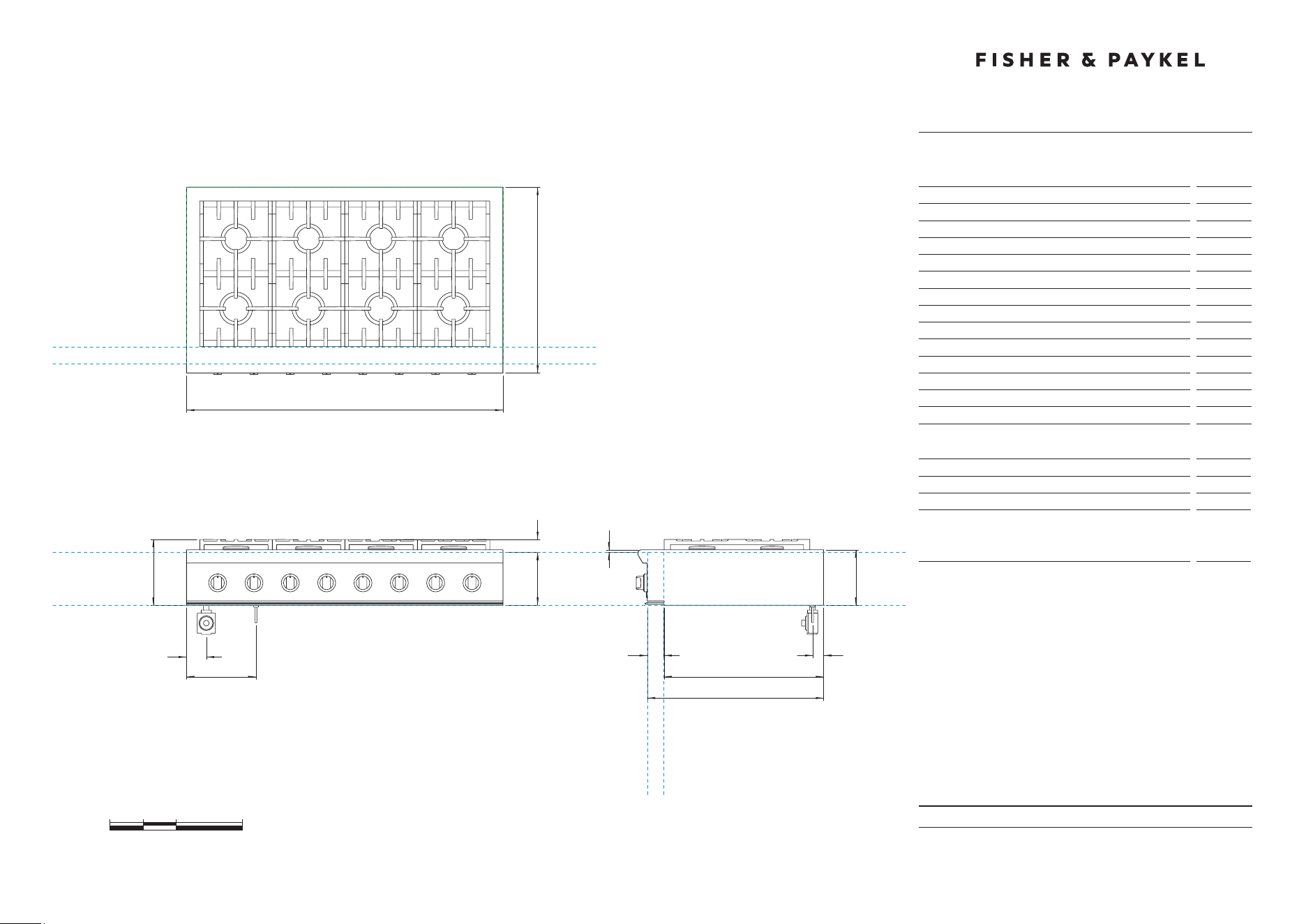
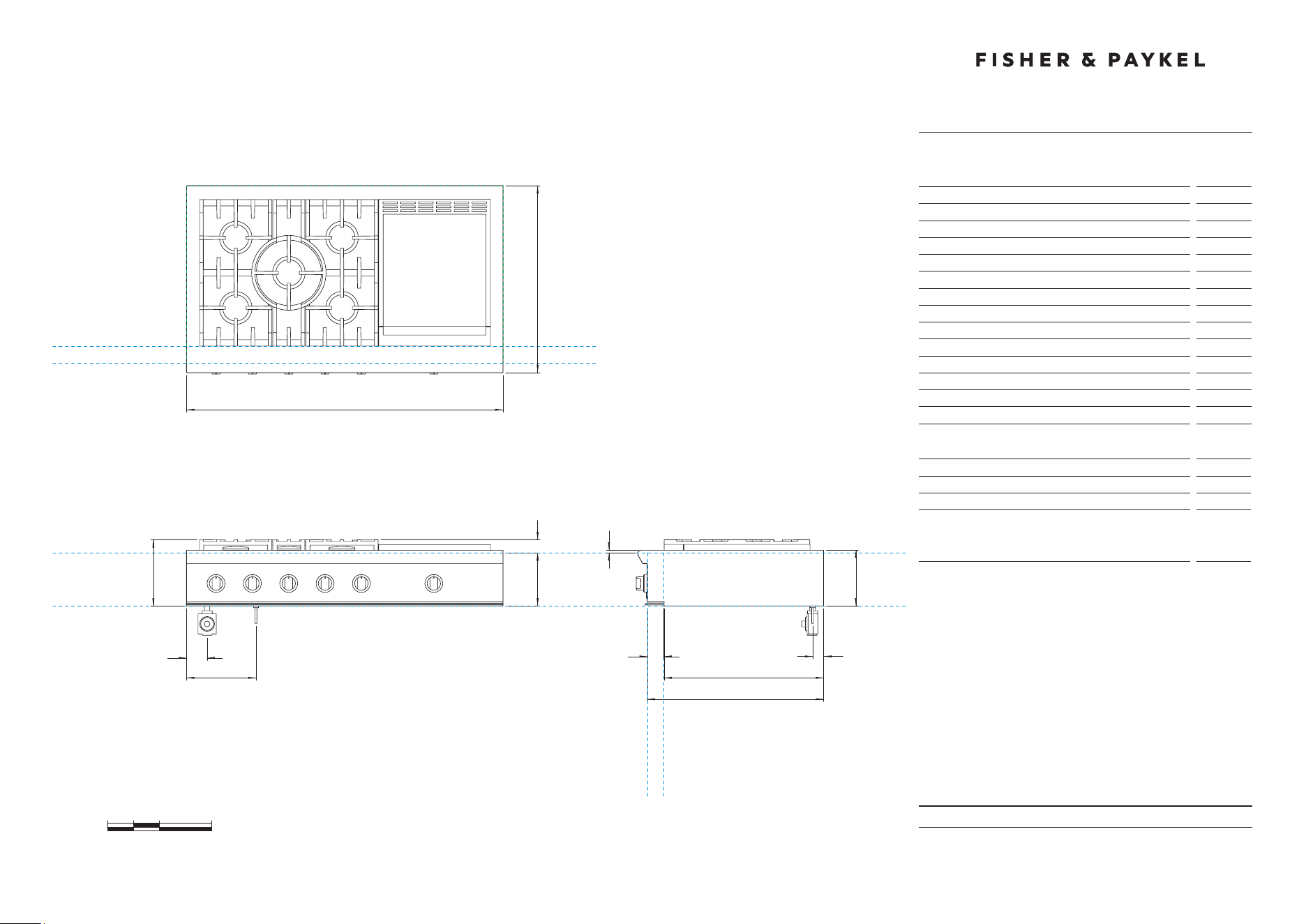
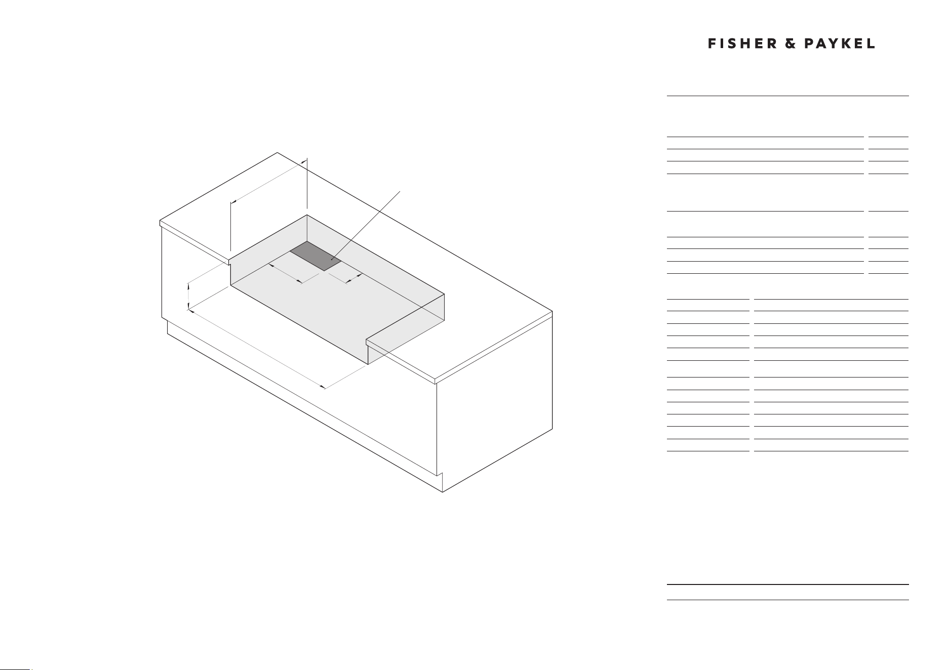
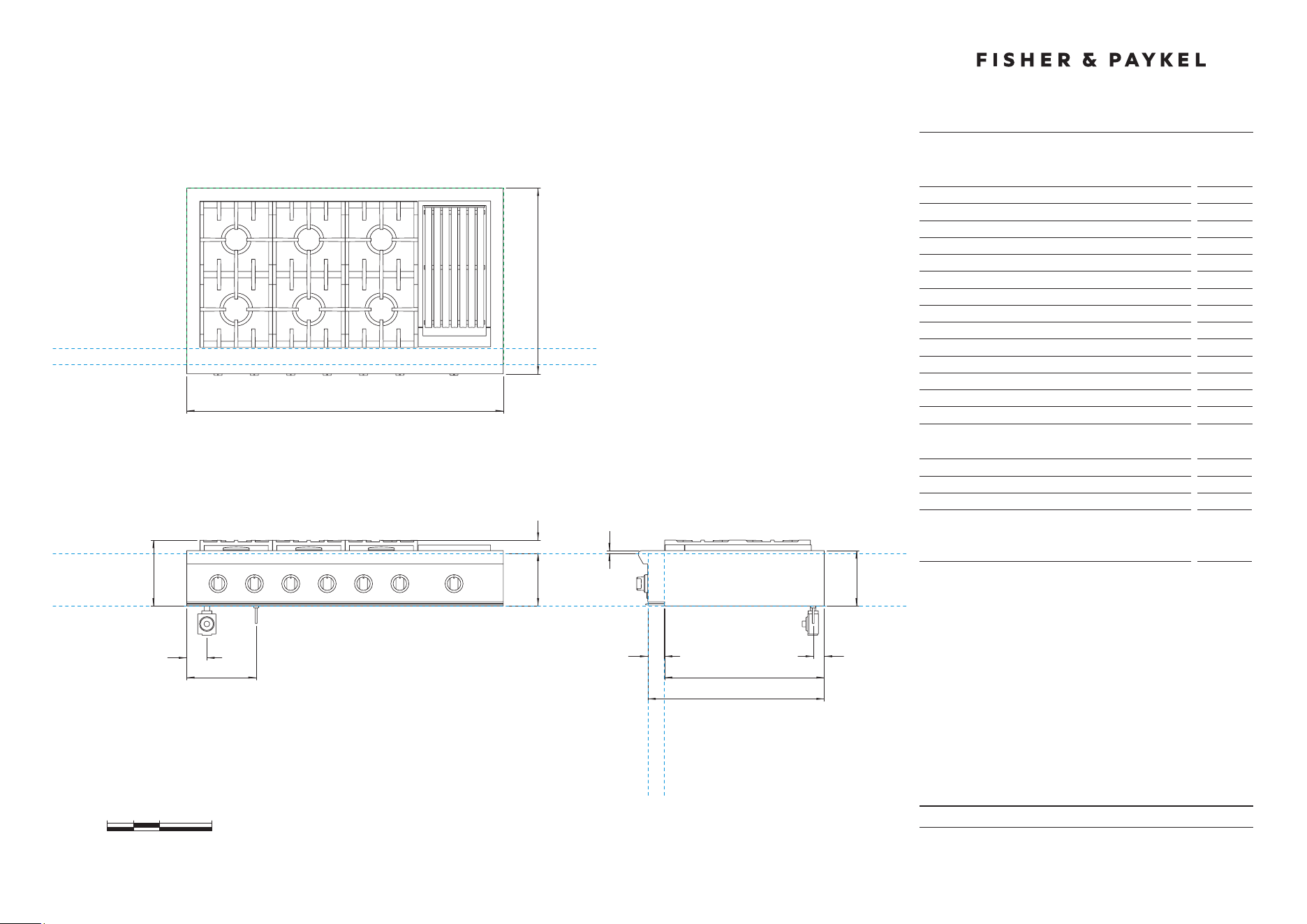
PRODUCT & CAVITY DIMENSIONS
48" Professional Gas Cooktop
DATE: 24.04.2018
IMPORTANT: Throughout this guide, dimensions may vary by ±2mm (1/16'').
Read the installation manual for detailed information on installing the product.
For full installation instructions and specifications visit fisherpaykel.com
0 5 10 20
inches
CABINET FACE FOR
INSTALLATION WITH
PROJECTING CONTROL
PANEL
CABINET FACE FOR
INSTALLATION WITH
FLUSH CONTROL PANEL
DATUM :
TOP OF
COUNTERTOP
DATUM :
CABINET SURFACE
BELOW COOKTOP
47 7/8''
C
F
28 1/8''
D
E
A
FRONT VIEW
PLAN VIEW
G
PROFILE VIEW
I
H
B
J
K
L
CABINET FACE FOR INSTALLATION
WITH PROJECTING CONTROL PANEL
CABINET FACE FOR INSTALLATION
WITH FLUSH CONTROL PANEL
M
8''
Model no:
CPV2-485
Product Dimensions
in
A Height below countertop datum to bottom of chassis
8''
B Overall height of product (bottom of chassis to top of grates)
9 15/16''
C Overall width of cooktop
47 7/8''
D Overall depth of cooktop
28 1/8''
E Height above countertop datum to top of grates
1 15/16''
F Height from countertop datum to chassis top surface
3/8''
G Height of chassis
8 3/8''
H Depth from rear of chassis to cabinetry datum - projecting
24 3/16''
I Depth from rear of chassis to cabinetry datum - flush
26 11/16
''
J Depth of control panel
2 1/2''
K Distance from left edge of chassis to center line of gas inlet
3''
L Distance from left edge of chassis to center line of power cord
10 1/2''
M Distance from rear edge of chassis to center line of gas/power
1 5/8''
Cutout Dimensions
in
Overall height of cutout
8''
Overall width of cutout
min 48''
Overall depth of cutout for projecting control panel
Overall depth of cutout for flush control panel
max
24 3/16''
max
26 11/16''
INDICATES CABINETRY DATUM -----------------------------------------
INDICATES CUTOUT -------------------------------------------------------
DATE: 24.04.2018
IMPORTANT: Throughout this guide, dimensions may vary by ±2mm (1/16'').
Read the installation manual for detailed information on installing the product.
For full installation instructions and specifications visit fisherpaykel.com
INDICATES CABINETRY CLEARANCES --------------------------------
INDICATES PRODUCT DATUM -------------------------------------------
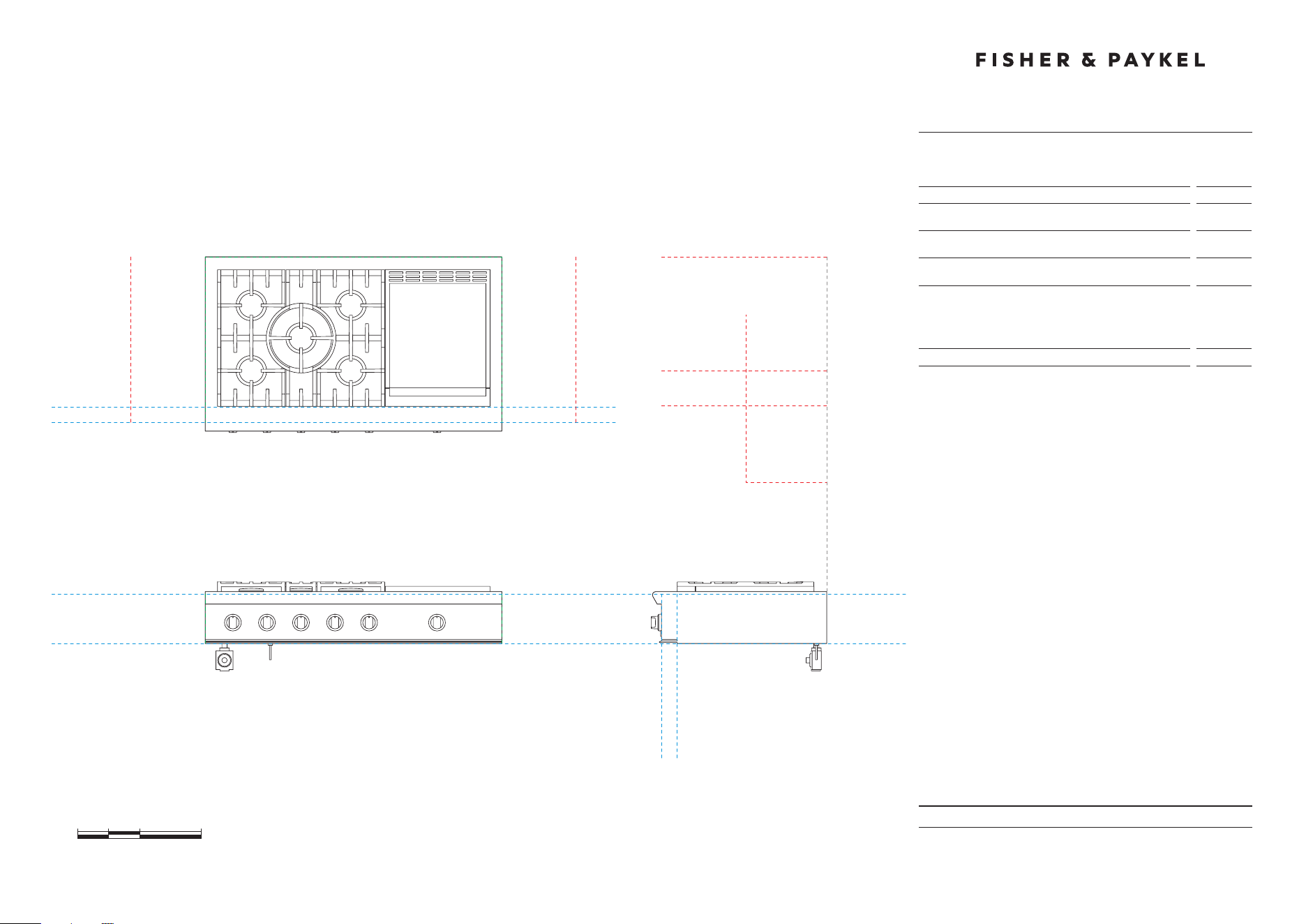
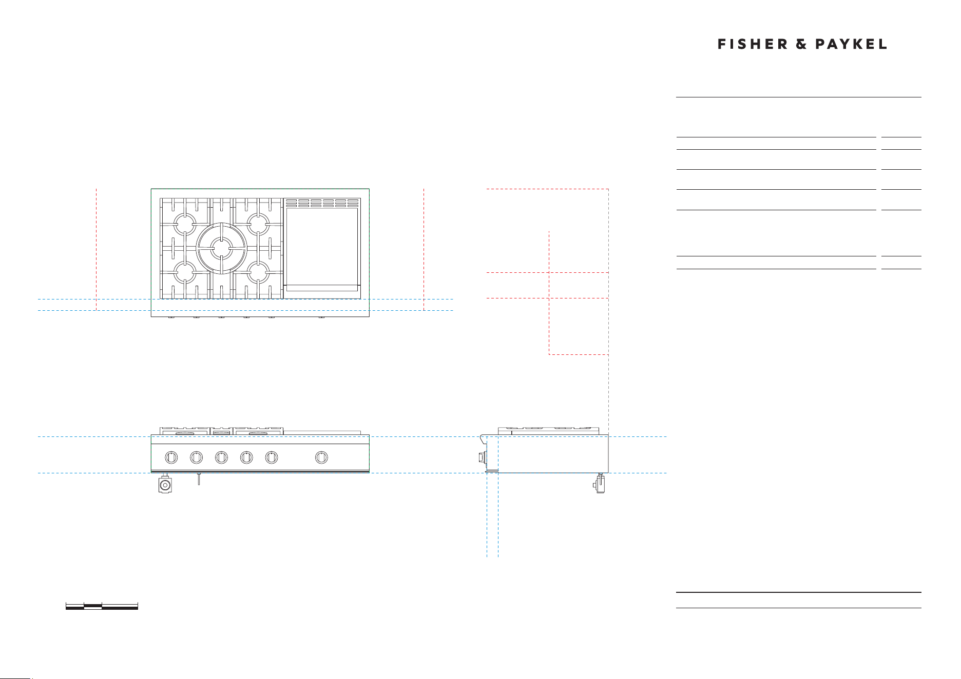
CLEARANCE DIMENSIONS
48" Professional Gas Cooktop
Model no:
CPV2-485
Cabinetry Dimensions
in
A Minimum width of ventilation hood installed above cooktop
- not shown*
48''
B Minimum vertical distance between countertop and cabinet
extending above counter
18''
C Minimum clearance from left and right edge of range to
nearest vertical combustible surface
12''
D Minimum clearance from cooking surface to:
– combustible surface centered above the cooking surface
– combustible covering for ventilation hood centered above
the cooking surface
– non-combustible surface centered above the cooking surface
54''
36''
30''
E Maximum overall depth of overhead cabinetry
13''
DATUM : BOTTOM OF CHASSIS
FRONT VIEW PROFILE VIEW
DATUM :
TOP OF COUNTERTOP
CABINET FACE FOR
INSTALLATION WITH
PROJECTING CONTROL PANEL
CABINET FACE FOR
INSTALLATION WITH
FLUSH CONTROL PANEL
PLAN VIEW
MINIMUM CLEARANCE:
COMBUSTIBLE SURFACE
MAXIMUM OVERALL DEPTH
OF OVERHEAD CABINETRY
MINIMUM CLEARANCE:
ADJACENT OVERHEAD CABINET
MINIMUM CLEARANCE:
NON-COMBUSTIBLE SURFACE
MINIMUM CLEARANCE:
VENTILATION HOOD
MINIMUM CLEARANCE:
NEAREST VERTICAL
COMBUSTIBLE SURFACE
MINIMUM CLEARANCE:
NEAREST VERTICAL
COMBUSTIBLE SURFACE
CABINET FACE FOR INSTALLATION
WITH PROJECTING CONTROL PANEL
CABINET FACE FOR INSTALLATION
WITH FLUSH CONTROL PANEL
0 5 10 20
inches
D
E
D
D
B
CC

DATE: 24.04.2018
IMPORTANT: Throughout this guide, dimensions may vary by ±2mm (1/16'').
Read the installation manual for detailed information on installing the product.
For full installation instructions and specifications visit fisherpaykel.com
CAVITY PREPARATION
48" Professional Gas Cooktop
Model no:
CPV2-485
Cavity Dimensions
in
A Overall height of cutout
8''
B Overall width of cutout
min 48''
C Overall depth of cutout for projecting control panel
Overall depth of cutout for flush control panel
max
24 3/16''
max
26 11/16''
Electrical and Gas Supply Cutout
in
D Depth of supply area from rear of cutout
6''
E Width of supply area from left side of cutout
12''
Specifications
48" Models
Electrical
Supply
120 VAC, 60Hz
Max. Current Draw
15 amp
Service
15 amp circuit
Gas – Natural
Connection
1/2” NPT Minimum 5/8” dia. flex line
Supply Pressure
Supply Pressure: 6” to 9” W.C.
Gas – LP
Connection
1/2” NPT Minimum 5/8” dia. flex line
Supply Pressure*
11” to 14” W.C.
A regulator is required at the LP source to provide a maximum pressure
of 14” W.C. to the cooktop regulator.
B
C
A
e
D
ELECTRICAL & GAS
SUPPLY CUTOUT

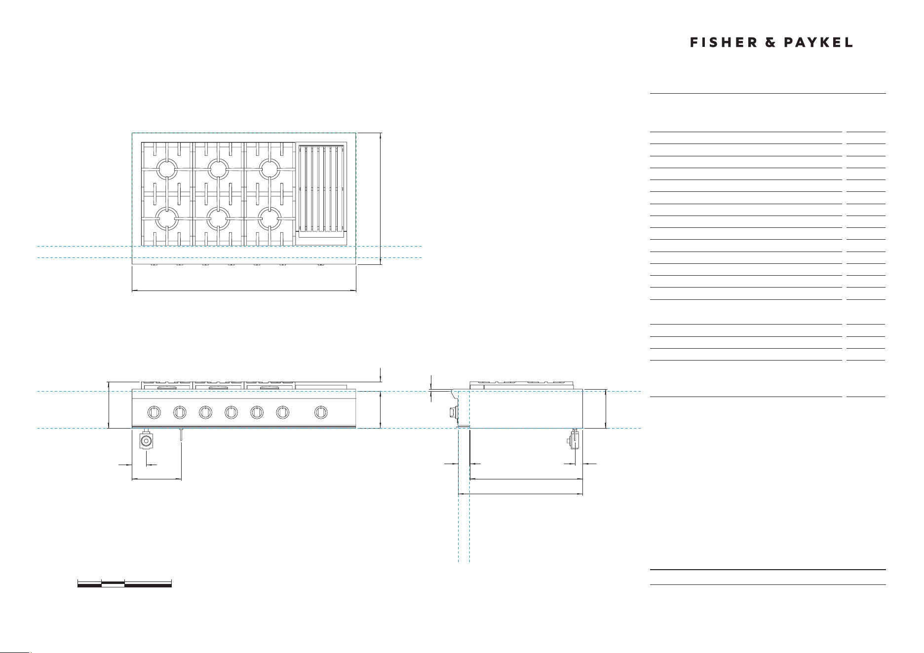
PRODUCT & CAVITY DIMENSIONS
48" Professional Gas Cooktop
DATE: 24.04.2018
IMPORTANT: Throughout this guide, dimensions may vary by ±2mm (1/16'').
Read the installation manual for detailed information on installing the product.
For full installation instructions and specifications visit fisherpaykel.com
INDICATES CABINETRY DATUM -----------------------------------------
INDICATES CUTOUT -------------------------------------------------------
0 5 10 20
inches
CABINET FACE FOR
INSTALLATION WITH
PROJECTING CONTROL
PANEL
CABINET FACE FOR
INSTALLATION WITH
FLUSH CONTROL PANEL
DATUM :
TOP OF
COUNTERTOP
DATUM :
CABINET SURFACE
BELOW COOKTOP
47 7/8''
C
F
28 1/8''
D
E
A
FRONT VIEW
PLAN VIEW
G
PROFILE VIEW
I
H
B
J
K
L
CABINET FACE FOR INSTALLATION
WITH PROJECTING CONTROL PANEL
CABINET FACE FOR INSTALLATION
WITH FLUSH CONTROL PANEL
M
8''
Model no:
CPV2-486GD
Product Dimensions
in
A Height below countertop datum to bottom of chassis
8''
B Overall height of product (bottom of chassis to top of grates)
9 15/16''
C Overall width of cooktop
47 7/8''
D Overall depth of cooktop
28 1/8''
E Height above countertop datum to top of grates
1 15/16''
F Height from countertop datum to chassis top surface
3/8''
G Height of chassis
8 3/8''
H Depth from rear of chassis to cabinetry datum - projecting
24 3/16''
I Depth from rear of chassis to cabinetry datum - flush
26 11/16
''
J Depth of control panel
2 1/2''
K Distance from left edge of chassis to center line of gas inlet
3''
L Distance from left edge of chassis to center line of power cord
10 1/2''
M Distance from rear edge of chassis to center line of gas/power
1 5/8''
Cutout Dimensions
in
Overall height of cutout
8''
Overall width of cutout
min 48''
Overall depth of cutout for projecting control panel
Overall depth of cutout for flush control panel
max
24 3/16''
max
26 11/16''

DATE: 24.04.2018
IMPORTANT: Throughout this guide, dimensions may vary by ±2mm (1/16'').
Read the installation manual for detailed information on installing the product.
For full installation instructions and specifications visit fisherpaykel.com
INDICATES CABINETRY CLEARANCES --------------------------------
INDICATES PRODUCT DATUM -------------------------------------------
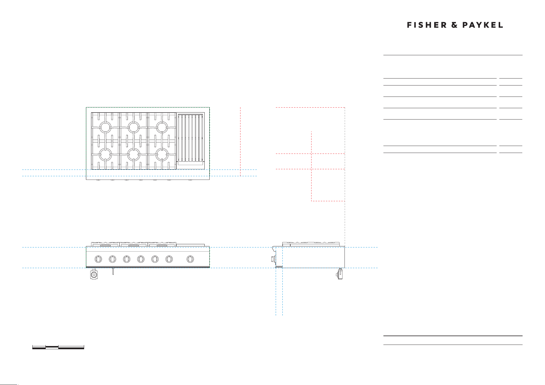
CLEARANCE DIMENSIONS
48" Professional Gas Cooktop
Model no:
CPV2-486GD
Cabinetry Dimensions
in
A Minimum width of ventilation hood installed above cooktop
- not shown*
48''
B Minimum vertical distance between countertop and cabinet
extending above counter
18''
C Minimum clearance from left and right edge of range to
nearest vertical combustible surface
12''
D Minimum clearance from cooking surface to:
– combustible surface centered above the cooking surface
– combustible covering for ventilation hood centered above
the cooking surface
– non-combustible surface centered above the cooking surface
54''
36''
30''
E Maximum overall depth of overhead cabinetry
13''
DATUM : BOTTOM OF CHASSIS
FRONT VIEW PROFILE VIEW
DATUM :
TOP OF COUNTERTOP
CABINET FACE FOR
INSTALLATION WITH
PROJECTING CONTROL PANEL
CABINET FACE FOR
INSTALLATION WITH
FLUSH CONTROL PANEL
PLAN VIEW
MINIMUM CLEARANCE:
COMBUSTIBLE SURFACE
MAXIMUM OVERALL DEPTH
OF OVERHEAD CABINETRY
MINIMUM CLEARANCE:
ADJACENT OVERHEAD CABINET
MINIMUM CLEARANCE:
NON-COMBUSTIBLE SURFACE
MINIMUM CLEARANCE:
NEAREST VERTICAL
COMBUSTIBLE SURFACE
MINIMUM CLEARANCE:
NEAREST VERTICAL
COMBUSTIBLE SURFACE
CABINET FACE FOR INSTALLATION
WITH PROJECTING CONTROL PANEL
CABINET FACE FOR INSTALLATION
WITH FLUSH CONTROL PANEL
0 5 10 20
inches
D
E
D
B
CC
MINIMUM CLEARANCE:
VENTILATION HOOD
D

DATE: 24.04.2018
IMPORTANT: Throughout this guide, dimensions may vary by ±2mm (1/16'').
Read the installation manual for detailed information on installing the product.
For full installation instructions and specifications visit fisherpaykel.com
CAVITY PREPARATION
48" Professional Gas Cooktop
Model no:
CPV2-486GD
Cavity Dimensions
in
A Overall height of cutout
8''
B Overall width of cutout
min 48''
C Overall depth of cutout for projecting control panel
Overall depth of cutout for flush control panel
max
24 3/16''
max
26 11/16''
Electrical and Gas Supply Cutout
in
D Depth of supply area from rear of cutout
6''
E Width of supply area from left side of cutout
12''
Specifications
48" Models
Electrical
Supply
120 VAC, 60Hz
Max. Current Draw
15 amp
Service
15 amp circuit
Gas – Natural
Connection
1/2” NPT Minimum 5/8” dia. flex line
Supply Pressure
Supply Pressure: 6” to 9” W.C.
Gas – LP
Connection
1/2” NPT Minimum 5/8” dia. flex line
Supply Pressure*
11” to 14” W.C.
A regulator is required at the LP source to provide a maximum pressure
of 14” W.C. to the cooktop regulator.
e
B
C
D
A
ELECTRICAL & GAS
SUPPLY CUTOUT
PRODUCT & CAVITY DIMENSIONS
48" Professional Gas Cooktop
DATE: 24.04.2018
IMPORTANT: Throughout this guide, dimensions may vary by ±2mm (1/16'').
Read the installation manual for detailed information on installing the product.
For full installation instructions and specifications visit fisherpaykel.com
INDICATES CABINETRY DATUM -----------------------------------------
INDICATES CUTOUT -------------------------------------------------------
0 5 10 20
inches
CABINET FACE FOR
INSTALLATION WITH
PROJECTING CONTROL
PANEL
CABINET FACE FOR
INSTALLATION WITH
FLUSH CONTROL PANEL
DATUM :
TOP OF
COUNTERTOP
DATUM :
CABINET SURFACE
BELOW COOKTOP
47 7/8''
C
F
28 1/8''
D
E
A
FRONT VIEW
PLAN VIEW
G
PROFILE VIEW
I
H
B
J
K
L
CABINET FACE FOR INSTALLATION
WITH PROJECTING CONTROL PANEL
CABINET FACE FOR INSTALLATION
WITH FLUSH CONTROL PANEL
M
8''
Model no:
CPV2-486GL
Product Dimensions
in
A Height below countertop datum to bottom of chassis
8''
B Overall height of product (bottom of chassis to top of grates)
9 15/16''
C Overall width of cooktop
47 7/8''
D Overall depth of cooktop
28 1/8''
E Height above countertop datum to top of grates
1 15/16''
F Height from countertop datum to chassis top surface
3/8''
G Height of chassis
8 3/8''
H Depth from rear of chassis to cabinetry datum - projecting
24 3/16''
I Depth from rear of chassis to cabinetry datum - flush
26 11/16
''
J Depth of control panel
2 1/2''
K Distance from left edge of chassis to center line of gas inlet
3''
L Distance from left edge of chassis to center line of power cord
10 1/2''
M Distance from rear edge of chassis to center line of gas/power
1 5/8''
Cutout Dimensions
in
Overall height of cutout
8''
Overall width of cutout
min 48''
Overall depth of cutout for projecting control panel
Overall depth of cutout for flush control panel
max
24 3/16''
max
26 11/16''
DATE: 24.04.2018
IMPORTANT: Throughout this guide, dimensions may vary by ±2mm (1/16'').
Read the installation manual for detailed information on installing the product.
For full installation instructions and specifications visit fisherpaykel.com
NDICATES CABINETRY CLEARANCES ---------------------------------
INDICATES PRODUCT DATUM -------------------------------------------
CLEARANCE DIMENSIONS
48" Professional Gas Cooktop
Model no:
CPV2-486GL
Cabinetry Dimensions
in
A Minimum width of ventilation hood installed above cooktop
- not shown*
48''
B Minimum vertical distance between countertop and cabinet
extending above counter
18''
C Minimum clearance from left and right edge of range to
nearest vertical combustible surface
12''
D Minimum clearance from cooking surface to:
– combustible surface centered above the cooking surface
– combustible covering for ventilation hood centered above
the cooking surface
– non-combustible surface centered above the cooking surface
54''
36''
30''
E Maximum overall depth of overhead cabinetry
13''
DATUM : BOTTOM OF CHASSIS
FRONT VIEW PROFILE VIEW
DATUM :
TOP OF COUNTERTOP
CABINET FACE FOR
INSTALLATION WITH
PROJECTING CONTROL PANEL
CABINET FACE FOR
INSTALLATION WITH
FLUSH CONTROL PANEL
PLAN VIEW
MINIMUM CLEARANCE:
COMBUSTIBLE SURFACE
MAXIMUM OVERALL DEPTH
OF OVERHEAD CABINETRY
MINIMUM CLEARANCE:
ADJACENT OVERHEAD CABINET
MINIMUM CLEARANCE:
NON-COMBUSTIBLE SURFACE
MINIMUM CLEARANCE:
NEAREST VERTICAL
COMBUSTIBLE SURFACE
MINIMUM CLEARANCE:
NEAREST VERTICAL
COMBUSTIBLE SURFACE
CABINET FACE FOR INSTALLATION
WITH PROJECTING CONTROL PANEL
CABINET FACE FOR INSTALLATION
WITH FLUSH CONTROL PANEL
0 5 10 20
inches
D
E
D
B
CC
MINIMUM CLEARANCE:
VENTILATION HOOD
D

DATE: 24.04.2018
IMPORTANT: Throughout this guide, dimensions may vary by ±2mm (1/16'').
Read the installation manual for detailed information on installing the product.
For full installation instructions and specifications visit fisherpaykel.com
CAVITY PREPARATION
48" Professional Gas Cooktop
Model no:
CPV2-486GL
Cavity Dimensions
in
A Overall height of cutout
8''
B Overall width of cutout
min 48''
C Overall depth of cutout for projecting control panel
Overall depth of cutout for flush control panel
max
24 3/16''
max
26 11/16''
Electrical and Gas Supply Cutout
in
D Depth of supply area from rear of cutout
6''
E Width of supply area from left side of cutout
12''
Specifications
48" Models
Electrical
Supply
120 VAC, 60Hz
Max. Current Draw
15 amp
Service
15 amp circuit
Gas – Natural
Connection
1/2” NPT Minimum 5/8” dia. flex line
Supply Pressure
Supply Pressure: 6” to 9” W.C.
Gas – LP
Connection
1/2” NPT Minimum 5/8” dia. flex line
Supply Pressure*
11” to 14” W.C.
A regulator is required at the LP source to provide a maximum pressure
of 14” W.C. to the cooktop regulator.
e
B
C
D
A
ELECTRICAL & GAS
SUPPLY CUTOUT
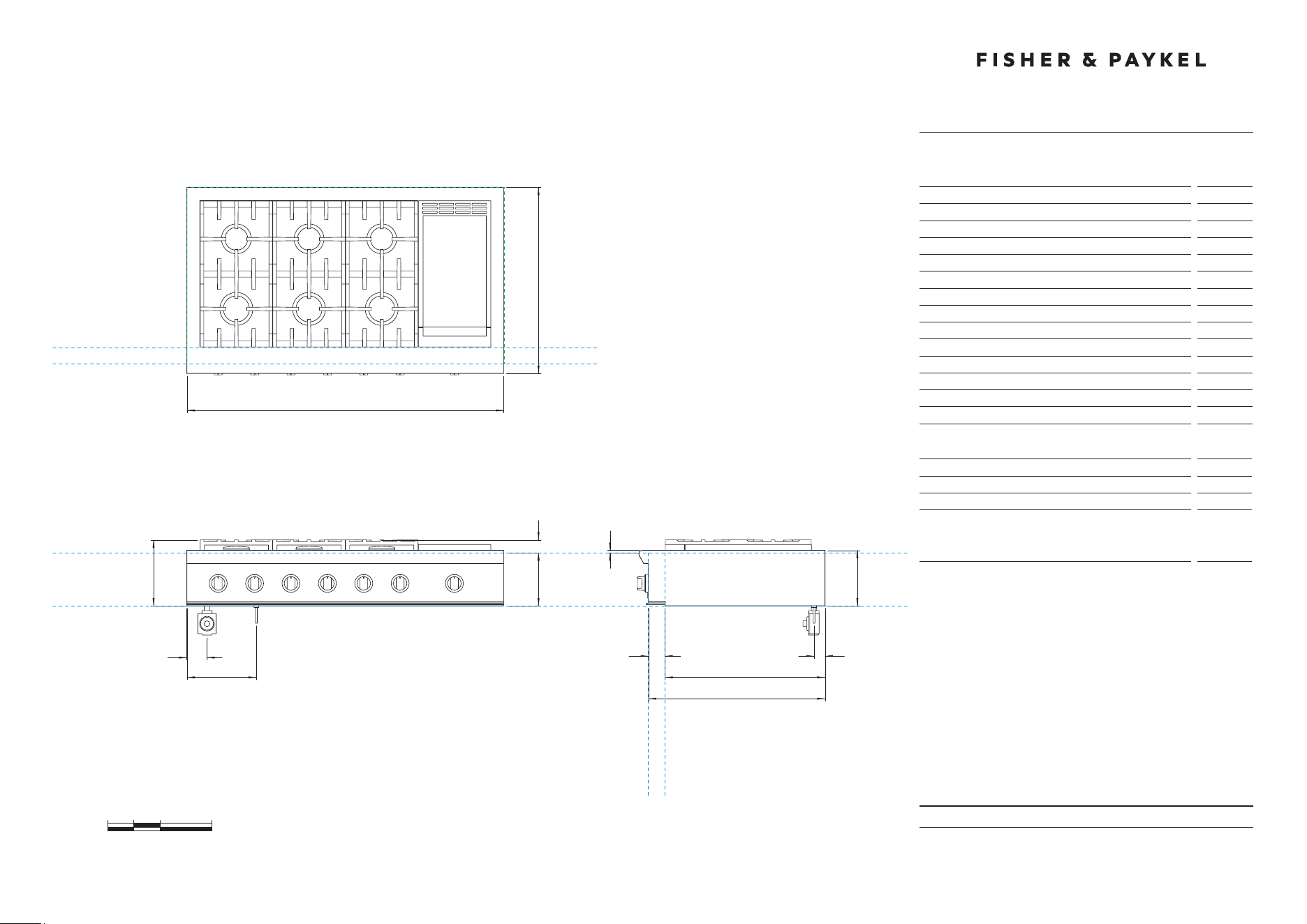
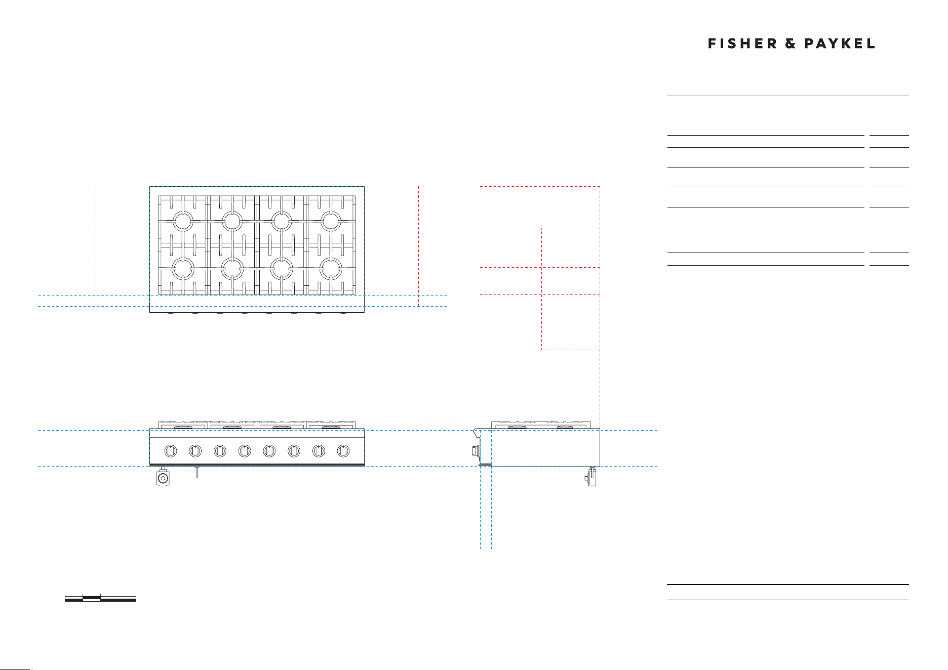
PRODUCT & CAVITY DIMENSIONS
48" Professional Gas Cooktop
DATE: 24.04.2018
IMPORTANT: Throughout this guide, dimensions may vary by ±2mm (1/16'').
Read the installation manual for detailed information on installing the product.
For full installation instructions and specifications visit fisherpaykel.com
INDICATES CABINETRY DATUM -----------------------------------------
INDICATES CUTOUT -------------------------------------------------------
0 5 10 20
inches
CABINET FACE FOR
INSTALLATION WITH
PROJECTING CONTROL
PANEL
CABINET FACE FOR
INSTALLATION WITH
FLUSH CONTROL PANEL
DATUM :
TOP OF
COUNTERTOP
DATUM :
CABINET SURFACE
BELOW COOKTOP
47 7/8''
C
F
28 1/8''
D
E
A
FRONT VIEW
PLAN VIEW
G
PROFILE VIEW
I
H
B
J
K
L
CABINET FACE FOR INSTALLATION
WITH PROJECTING CONTROL PANEL
CABINET FACE FOR INSTALLATION
WITH FLUSH CONTROL PANEL
M
8''
Model no:
CPV2-488
Product Dimensions
in
A Height below countertop datum to bottom of chassis
8''
B Overall height of product (bottom of chassis to top of grates)
9 15/16''
C Overall width of cooktop
47 7/8''
D Overall depth of cooktop
28 1/8''
E Height above countertop datum to top of grates
1 15/16''
F Height from countertop datum to chassis top surface
3/8''
G Height of chassis
8 3/8''
H Depth from rear of chassis to cabinetry datum - projecting
24 3/16''
I Depth from rear of chassis to cabinetry datum - flush
26 11/16
''
J Depth of control panel
2 1/2''
K Distance from left edge of chassis to center line of gas inlet
3''
L Distance from left edge of chassis to center line of power cord
10 1/2''
M Distance from rear edge of chassis to center line of gas/power
1 5/8''
Cutout Dimensions
in
Overall height of cutout
8''
Overall width of cutout
min 48''
Overall depth of cutout for projecting control panel
Overall depth of cutout for flush control panel
max
24 3/16''
max
26 11/16''

DATE: 24.04.2018
IMPORTANT: Throughout this guide, dimensions may vary by ±2mm (1/16'').
Read the installation manual for detailed information on installing the product.
For full installation instructions and specifications visit fisherpaykel.com
INDICATES CABINETRY CLEARANCES --------------------------------
INDICATES PRODUCT DATUM -------------------------------------------
CLEARANCE DIMENSIONS
48" Professional Gas Cooktop
Model no:
CPV2-488
Cabinetry Dimensions
in
A Minimum width of ventilation hood installed above cooktop
- not shown*
48''
B Minimum vertical distance between countertop and cabinet
extending above counter
18''
C Minimum clearance from left and right edge of range to
nearest vertical combustible surface
12''
D Minimum clearance from cooking surface to:
– combustible surface centered above the cooking surface
– combustible covering for ventilation hood centered above
the cooking surface
– non-combustible surface centered above the cooking surface
54''
36''
30''
E Maximum overall depth of overhead cabinetry
13''
DATUM : BOTTOM OF CHASSIS
FRONT VIEW PROFILE VIEW
DATUM :
TOP OF COUNTERTOP
CABINET FACE FOR
INSTALLATION WITH
PROJECTING CONTROL PANEL
CABINET FACE FOR
INSTALLATION WITH
FLUSH CONTROL PANEL
PLAN VIEW
MINIMUM CLEARANCE:
COMBUSTIBLE SURFACE
MAXIMUM OVERALL DEPTH
OF OVERHEAD CABINETRY
MINIMUM CLEARANCE:
ADJACENT OVERHEAD CABINET
MINIMUM CLEARANCE:
NON-COMBUSTIBLE SURFACE
MINIMUM CLEARANCE:
NEAREST VERTICAL
COMBUSTIBLE SURFACE
MINIMUM CLEARANCE:
NEAREST VERTICAL
COMBUSTIBLE SURFACE
CABINET FACE FOR INSTALLATION
WITH PROJECTING CONTROL PANEL
CABINET FACE FOR INSTALLATION
WITH FLUSH CONTROL PANEL
0 5 10 20
inches
D
E
D
B
CC
MINIMUM CLEARANCE:
VENTILATION HOOD
D

DATE: 24.04.2018
IMPORTANT: Throughout this guide, dimensions may vary by ±2mm (1/16'').
Read the installation manual for detailed information on installing the product.
For full installation instructions and specifications visit fisherpaykel.com
CAVITY PREPARATION
48" Professional Gas Cooktop
Model no:
CPV2-488
Cavity Dimensions
in
A Overall height of cutout
8''
B Overall width of cutout
min 48''
C Overall depth of cutout for projecting control panel
Overall depth of cutout for flush control panel
max
24 3/16''
max
26 11/16''
Electrical and Gas Supply Cutout
in
D Depth of supply area from rear of cutout
6''
E Width of supply area from left side of cutout
12''
Specifications
48" Models
Electrical
Supply
120 VAC, 60Hz
Max. Current Draw
15 amp
Service
15 amp circuit
Gas – Natural
Connection
1/2” NPT Minimum 5/8” dia. flex line
Supply Pressure
Supply Pressure: 6” to 9” W.C.
Gas – LP
Connection
1/2” NPT Minimum 5/8” dia. flex line
Supply Pressure*
11” to 14” W.C.
A regulator is required at the LP source to provide a maximum pressure
of 14” W.C. to the cooktop regulator.
e
B
C
D
A
ELECTRICAL & GAS
SUPPLY CUTOUT
DATE: 24.04.2018
IMPORTANT: Throughout this guide, dimensions may vary by ±2mm (1/16'').
Read the installation manual for detailed information on installing the product.
For full installation instructions and specifications visit fisherpaykel.com
INDICATES PRODUCT DATUM -------------------------------------------
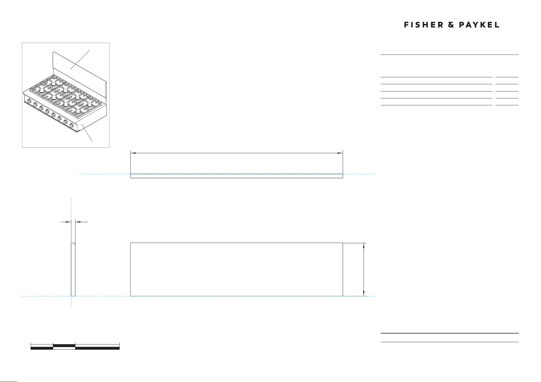
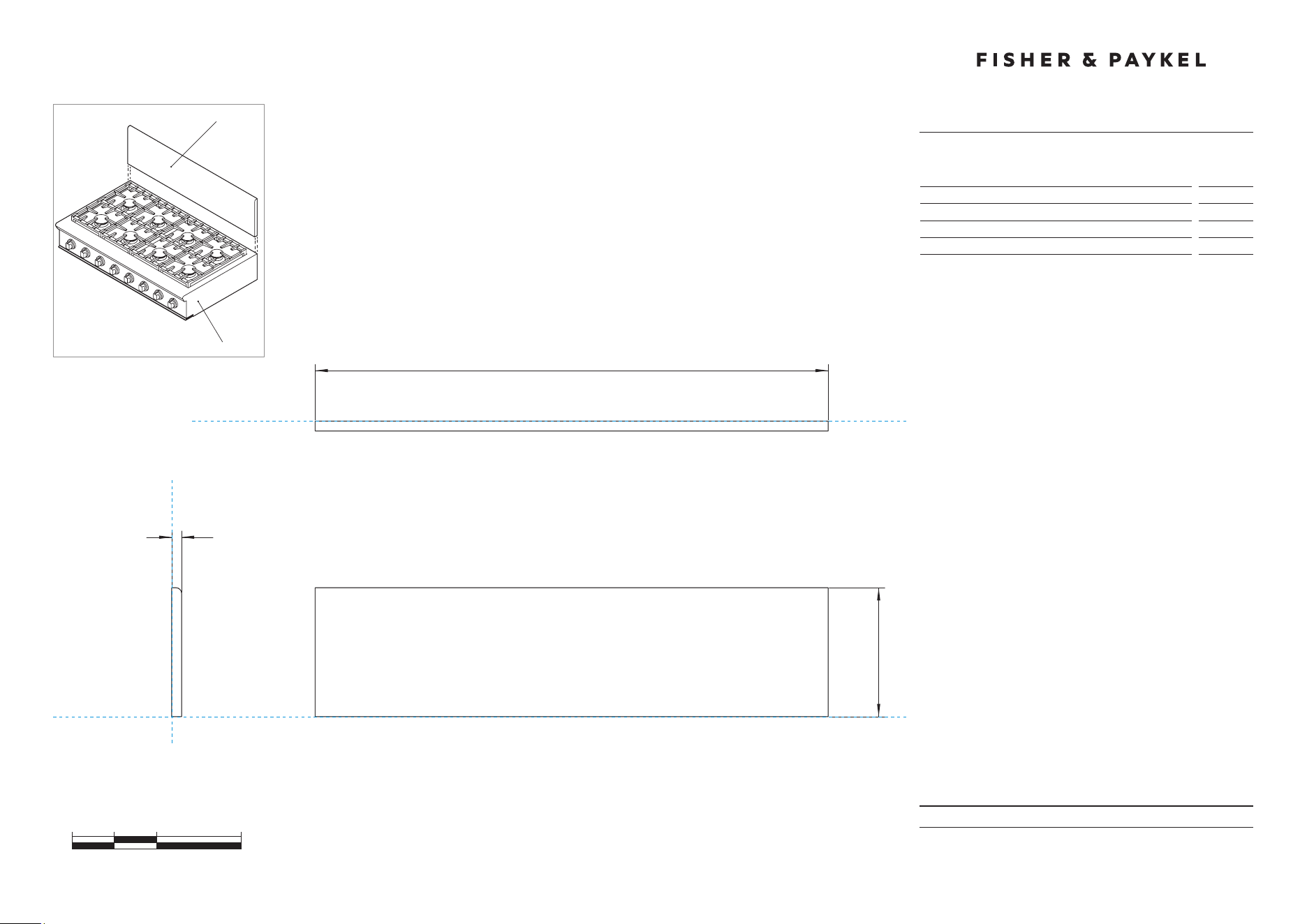
PRODUCT DIMENSIONS
48" Professional Cooktop Backguard
0 5 10 20
inches
47 7/ 8 ''
B
12''
15/16''
A
FRONT VIEW
PLAN VIEW
c
DATUM : BOTTOM OF PRODUCT
DATUM : BACK OF PRODUCT
DATUM : BACK OF PRODUCT
NOT TO SCALE
PROFILE VIEW
BGCV2-1248
CPV2-488
Model no:
BGCV2-1248
Product Dimensions
in
A Overall height of backguard
12
''
B Overall width of backguard
47 7/ 8
''
C Overall depth of backguard
15/16
''
DATE: 24.04.2018
IMPORTANT: Throughout this guide, dimensions may vary by ±2mm (1/16'').
Read the installation manual for detailed information on installing the product.
For full installation instructions and specifications visit fisherpaykel.com
INDICATES PRODUCT DATUM -------------------------------------------
PRODUCT DIMENSIONS
48" Professional Cooktop Backguard
0 5 10 20
inches
47 7/8"
B
47 7/8"
B
30"
15/16"
A
f
e
h
g
i
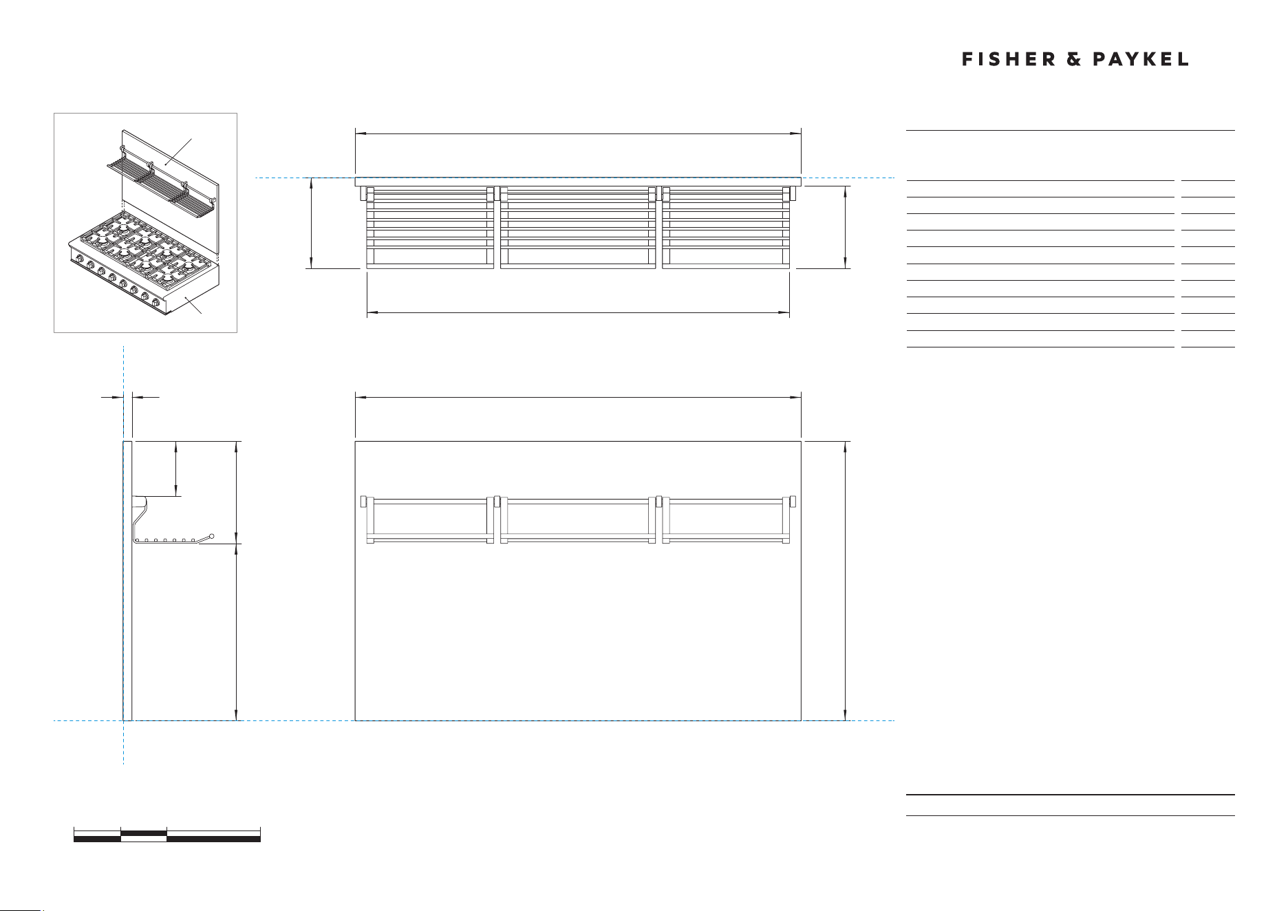
FRONT VIEW
PLAN VIEW
PROFILE VIEW
c
DATUM : BOTTOM OF PRODUCT
DATUM : BACK OF PRODUCT
DATUM : BACK OF PRODUCT
d
BGCV2-3048
CPV2-488
NOT TO SCALE
Model no:
BGCV2-3048
Product Dimensions
in
A Overall height of backguard
30"
B Overall width of backguard
47 7/8"
C Overall depth of backguard and racks
9 3/4"
D Depth of backguard
15/16"
E Depth of racks
8 13/16"
F Width of racks
45 3/8"
G Distance from top of backguard to bottom of racks
10 15/16"
H Distance from bottom of backguard to bottom of racks
19 1/16"
I Distance from top of backguard to top of brackets
5 7/8"
DATE: 24.04.2018
IMPORTANT: Throughout this guide, dimensions may vary by ±2mm (1/16'').
Read the installation manual for detailed information on installing the product.
For full installation instructions and specifications visit fisherpaykel.com
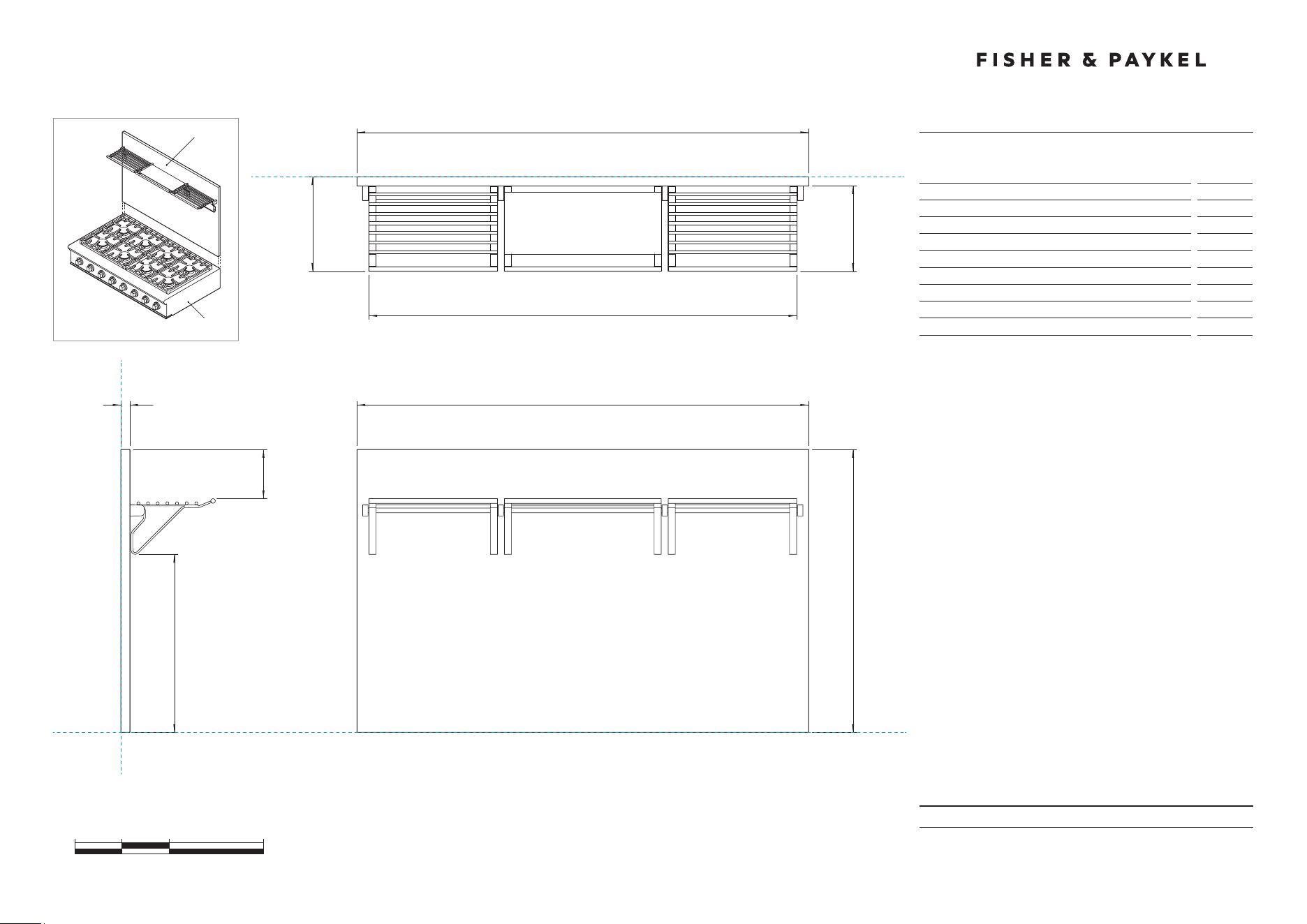
INDICATES PRODUCT DATUM -------------------------------------------
PRODUCT DIMENSIONS
48" Professional Cooktop Backguard
A
f
e
h
g
FRONT VIEW
PLAN VIEW
PROFILE VIEW
c
DATUM : BOTTOM OF PRODUCT
DATUM : BACK OF PRODUCT
DATUM : BACK OF PRODUCT
d
BGCV2-3048H
CPV2-488
NOT TO SCALE
0 5 10 20
inches
47 7/8"
B
47 7/8"
B
30"
15/16"
Model no:
BGCV2-3048H
Product Dimensions
in
A Overall height of backguard
30"
B Overall width of backguard
47 7/8"
C Overall depth of backguard and racks
10"
D Depth of backguard
15/16"
E Depth of racks
9 1/16"
F Width of racks
45 3/8"
G Distance from top of backguard to top of racks
5 3/8"
H Distance from bottom of backguard to bottom of racks
18 7/8"

METRIC

DATE: 24.04.2018
IMPORTANT: Throughout this guide, dimensions may vary by ±2mm (1/16'').
Read the installation manual for detailed information on installing the product.
For full installation instructions and specifications visit fisherpaykel.com
Model no:
CPV2-485, CPV2-486GD,
CPV2-488, CPV2-486GL
KEY DESIGN DECISIONS
48" Professional Range
MIN 152mm
CLEARANCE
MAX 24mm
MIN 762mm
INSTALL TYPE
1
WALL
ISLAND
REAR SURFACE
2
COMBUSTIBLE
NON COMBUSTIBLE
BACKGUARD OPTIONS
3
NO BACKGUARD
LOW BACKGUARD
LOW SHELF
HIGH BACKGUARD
HIGH SHELF
HIGH BACKGUARD
BGCV2-3048
BGCV2-3048H
BGRV2-1248
NO BACKGUARD
CUSTOM FABRICATED* BACKGUARD
*Fabricated from non combustible materials only
CUSTOM
BACKGUARD*
DATE: 24.04.2018
IMPORTANT: Throughout this guide, dimensions may vary by ±2mm (1/16'').
Read the installation manual for detailed information on installing the product.
For full installation instructions and specifications visit fisherpaykel.com
INSTALL TYPE
1
WALL
ISLAND
HOOD SURROUND MATERIAL
2
NON COMBUSTIBLE
NON COMBUSTIBLE
COMBUSTIBLE
COMBUSTIBLE
VENTILATION REQUIREMENTS
48" Professional Gas Cooktop
MIN
914mm
584mm
MIN
762mm
MAX
914mm
MIN 762mm
MAX 914mm
762mm
762mm
MIN 914mm
584mm
Model no:
CPV2-485, CPV2-486GD,
CPV2-488, CPV2-486GL
Note: CPV2-366 illustrated but all dimensions apply to the above models
Specifications
Ventilation Unit
Wall Installation
Hood
584mm Deep x Unit Width
Blower
1200 CFM
Ventilation Unit
Island Installation
Hood
762mm Deep x Unit Width
Blower
1200 CFM
Note: A suitable hood must be installed above the cooktop.
Theaboveindicates the minimum blower capacity recommended
for hood ventilation.
PRODUCT & CAVITY DIMENSIONS
48" Professional Gas Cooktop
DATE: 24.04.2018
IMPORTANT: Throughout this guide, dimensions may vary by ±2mm (1/16'').
Read the installation manual for detailed information on installing the product.
For full installation instructions and specifications visit fisherpaykel.com
INDICATES CABINETRY DATUM -----------------------------------------
INDICATES CUTOUT -------------------------------------------------------
0 100 200 400
millimetres
CABINET FACE FOR
INSTALLATION WITH
PROJECTING CONTROL
PANEL
CABINET FACE FOR
INSTALLATION WITH
FLUSH CONTROL PANEL
DATUM :
TOP OF
COUNTERTOP
DATUM :
CABINET SURFACE
BELOW COOKTOP
1216
C
F
714
D
E
A
FRONT VIEW
PLAN VIEW
G
PROFILE VIEW
I
H
B
J
K
L
CABINET FACE FOR INSTALLATION
WITH PROJECTING CONTROL PANEL
CABINET FACE FOR INSTALLATION
WITH FLUSH CONTROL PANEL
M
203
Model no:
CPV2-485
Product Dimensions
mm
A Height below countertop datum to bottom of chassis
203
B Overall height of product (bottom of chassis to top of grates)
253
C Overall width of cooktop
1216
D Overall depth of cooktop
714
E Height above countertop datum to top of grates
50
F Height from countertop datum to chassis top surface
10
G Height of chassis
213
H Depth from rear of chassis to cabinetry datum - projecting
614
I Depth from rear of chassis to cabinetry datum - flush
677
J Depth of control panel
64
K Distance from left edge of chassis to centre line of gas inlet
77
L Distance from left edge of chassis to centre line of power cord
267
M Distance from rear edge of chassis to centre line of gas/power
42
Cutout Dimensions
mm
Overall height of cutout
203
Overall width of cutout
min 1219
Overall depth of cutout for projecting control panel
Overall depth of cutout for flush control panel
max
614
max
678
DATE: 24.04.2018
IMPORTANT: Throughout this guide, dimensions may vary by ±2mm (1/16'').
Read the installation manual for detailed information on installing the product.
For full installation instructions and specifications visit fisherpaykel.com
INDICATES CABINETRY CLEARANCES --------------------------------
INDICATES PRODUCT DATUM -------------------------------------------
CLEARANCE DIMENSIONS
48" Professional Gas Cooktop
Model no:
CPV2-485
Cabinetry Dimensions
mm
A Minimum width of ventilation hood installed above cooktop
- not shown*
1219
B Minimum vertical distance between countertop and cabinet
extending above counter
457
C Minimum clearance from left and right edge of range to
nearest vertical combustible surface
305
D Minimum clearance from cooking surface to:
– combustible surface centered above the cooking surface
– combustible covering for ventilation hood centered above
the cooking surface
– non-combustible surface centered above the cooking surface
54''
36''
30''
E Maximum overall depth of overhead cabinetry
330
DATUM : BOTTOM OF CHASSIS
FRONT VIEW PROFILE VIEW
DATUM :
TOP OF COUNTERTOP
CABINET FACE FOR
INSTALLATION WITH
PROJECTING CONTROL PANEL
CABINET FACE FOR
INSTALLATION WITH
FLUSH CONTROL PANEL
PLAN VIEW
MINIMUM CLEARANCE:
COMBUSTIBLE SURFACE
MAXIMUM OVERALL DEPTH
OF OVERHEAD CABINETRY
MINIMUM CLEARANCE:
ADJACENT OVERHEAD CABINET
MINIMUM CLEARANCE:
NON-COMBUSTIBLE SURFACE
MINIMUM CLEARANCE:
NEAREST VERTICAL
COMBUSTIBLE SURFACE
MINIMUM CLEARANCE:
NEAREST VERTICAL
COMBUSTIBLE SURFACE
CABINET FACE FOR INSTALLATION
WITH PROJECTING CONTROL PANEL
CABINET FACE FOR INSTALLATION
WITH FLUSH CONTROL PANEL
D
E
D
B
CC
0 100 200 400
millimetres
MINIMUM CLEARANCE:
VENTILATION HOOD
D

DATE: 24.04.2018
IMPORTANT: Throughout this guide, dimensions may vary by ±2mm (1/16'').
Read the installation manual for detailed information on installing the product.
For full installation instructions and specifications visit fisherpaykel.com
CAVITY PREPARATION
48" Professional Gas Cooktop
Model no:
CPV2-485
Cavity Dimensions
mm
A Overall height of cutout
203
B Overall width of cutout
min 1219
C Overall depth of cutout for projecting control panel
Overall depth of cutout for flush control panel
max
614
max
678
Electrical and Gas Supply Cutout
mm
D Depth of supply area from rear of cutout
152
E Width of supply area from left side of cutout
305
Specifications
48" Models
Electrical
Supply
120 VAC, 60Hz
Max. Current Draw
15 amp
Service
15 amp circuit
Gas – Natural
Connection
1/2” NPT Minimum 5/8” dia. flex line
Supply Pressure
Supply Pressure: 6” to 9” W.C.
Gas – LP
Connection
1/2” NPT Minimum 5/8” dia. flex line
Supply Pressure*
11” to 14” W.C.
A regulator is required at the LP source to provide a maximum pressure
of 14” W.C. to the cooktop regulator.
e
B
C
D
A
ELECTRICAL & GAS
SUPPLY CUTOUT
PRODUCT & CAVITY DIMENSIONS
48" Professional Gas Cooktop
DATE: 24.04.2018
IMPORTANT: Throughout this guide, dimensions may vary by ±2mm (1/16'').
Read the installation manual for detailed information on installing the product.
For full installation instructions and specifications visit fisherpaykel.com
INDICATES CABINETRY DATUM -----------------------------------------
INDICATES CUTOUT -------------------------------------------------------
0 100 200 400
millimetres
CABINET FACE FOR
INSTALLATION WITH
PROJECTING CONTROL
PANEL
CABINET FACE FOR
INSTALLATION WITH
FLUSH CONTROL PANEL
DATUM :
TOP OF
COUNTERTOP
DATUM :
CABINET SURFACE
BELOW COOKTOP
1216
C
F
714
D
E
A
FRONT VIEW
PLAN VIEW
G
PROFILE VIEW
I
H
B
J
K
L
CABINET FACE FOR INSTALLATION
WITH PROJECTING CONTROL PANEL
CABINET FACE FOR INSTALLATION
WITH FLUSH CONTROL PANEL
M
203
Model no:
CPV2-486GD
Product Dimensions
mm
A Height below countertop datum to bottom of chassis
203
B Overall height of product (bottom of chassis to top of grates)
253
C Overall width of cooktop
1216
D Overall depth of cooktop
714
E Height above countertop datum to top of grates
50
F Height from countertop datum to chassis top surface
10
G Height of chassis
213
H Depth from rear of chassis to cabinetry datum - projecting
614
I Depth from rear of chassis to cabinetry datum - flush
677
J Depth of control panel
64
K Distance from left edge of chassis to centre line of gas inlet
77
L Distance from left edge of chassis to centre line of power cord
267
M Distance from rear edge of chassis to centre line of gas/power
42
Cutout Dimensions
mm
Overall height of cutout
203
Overall width of cutout
min 1219
Overall depth of cutout for projecting control panel
Overall depth of cutout for flush control panel
max
614
max
678

DATE: 24.04.2018
IMPORTANT: Throughout this guide, dimensions may vary by ±2mm (1/16'').
Read the installation manual for detailed information on installing the product.
For full installation instructions and specifications visit fisherpaykel.com
INDICATES CUTOUT -------------------------------------------------------
INDICATES CABINETRY CLEARANCES --------------------------------
INDICATES PRODUCT DATUM -------------------------------------------
CLEARANCE DIMENSIONS
48" Professional Gas Cooktop
Model no:
CPV2-486GD
Cabinetry Dimensions
mm
A Minimum width of ventilation hood installed above cooktop
- not shown*
1219
B Minimum vertical distance between countertop and cabinet
extending above counter
457
C Minimum clearance from left and right edge of range to
nearest vertical combustible surface
305
D Minimum clearance from cooking surface to:
– combustible surface centered above the cooking surface
– combustible covering for ventilation hood centered above
the cooking surface
– non-combustible surface centered above the cooking surface
54''
36''
30''
E Maximum overall depth of overhead cabinetry
330
DATUM : BOTTOM OF CHASSIS
FRONT VIEW PROFILE VIEW
DATUM :
TOP OF COUNTERTOP
CABINET FACE FOR
INSTALLATION WITH
PROJECTING CONTROL PANEL
CABINET FACE FOR
INSTALLATION WITH
FLUSH CONTROL PANEL
PLAN VIEW
MINIMUM CLEARANCE:
COMBUSTIBLE SURFACE
MAXIMUM OVERALL DEPTH
OF OVERHEAD CABINETRY
MINIMUM CLEARANCE:
ADJACENT OVERHEAD CABINET
MINIMUM CLEARANCE:
NON-COMBUSTIBLE SURFACE
MINIMUM CLEARANCE:
VENTILATION HOOD
MINIMUM CLEARANCE:
NEAREST VERTICAL
COMBUSTIBLE SURFACE
MINIMUM CLEARANCE:
NEAREST VERTICAL
COMBUSTIBLE SURFACE
CABINET FACE FOR INSTALLATION
WITH PROJECTING CONTROL PANEL
CABINET FACE FOR INSTALLATION
WITH FLUSH CONTROL PANEL
D
E
D
D
B
CC
0 100 200 400
millimetres
DATE: 24.04.2018
IMPORTANT: Throughout this guide, dimensions may vary by ±2mm (1/16'').
Read the installation manual for detailed information on installing the product.
For full installation instructions and specifications visit fisherpaykel.com
CAVITY PREPARATION
48" Professional Gas Cooktop
Model no:
CPV2-486GD
Cavity Dimensions
mm
A Overall height of cutout
203
B Overall width of cutout
min 1219
C Overall depth of cutout for projecting control panel
Overall depth of cutout for flush control panel
max
614
max
678
Electrical and Gas Supply Cutout
mm
D Depth of supply area from rear of cutout
152
E Width of supply area from left side of cutout
305
Specifications
48" Models
Electrical
Supply
120 VAC, 60Hz
Max. Current Draw
15 amp
Service
15 amp circuit
Gas – Natural
Connection
1/2” NPT Minimum 5/8” dia. flex line
Supply Pressure
Supply Pressure: 6” to 9” W.C.
Gas – LP
Connection
1/2” NPT Minimum 5/8” dia. flex line
Supply Pressure*
11” to 14” W.C.
A regulator is required at the LP source to provide a maximum pressure
of 14” W.C. to the cooktop regulator.
e
B
C
D
A
ELECTRICAL & GAS
SUPPLY CUTOUT
PRODUCT & CAVITY DIMENSIONS
48" Professional Gas Cooktop
DATE: 24.04.2018
IMPORTANT: Throughout this guide, dimensions may vary by ±2mm (1/16'').
Read the installation manual for detailed information on installing the product.
For full installation instructions and specifications visit fisherpaykel.com
INDICATES CABINETRY DATUM -----------------------------------------
INDICATES CUTOUT -------------------------------------------------------
0 100 200 400
millimetres
CABINET FACE FOR
INSTALLATION WITH
PROJECTING CONTROL
PANEL
CABINET FACE FOR
INSTALLATION WITH
FLUSH CONTROL PANEL
DATUM :
TOP OF
COUNTERTOP
DATUM :
CABINET SURFACE
BELOW COOKTOP
1216
C
F
714
D
E
A
FRONT VIEW
PLAN VIEW
G
PROFILE VIEW
I
H
B
J
K
L
CABINET FACE FOR INSTALLATION
WITH PROJECTING CONTROL PANEL
CABINET FACE FOR INSTALLATION
WITH FLUSH CONTROL PANEL
M
203
Model no:
CPV2-486GL
Product Dimensions
mm
A Height below countertop datum to bottom of chassis
203
B Overall height of product (bottom of chassis to top of grates)
253
C Overall width of cooktop
1216
D Overall depth of cooktop
714
E Height above countertop datum to top of grates
50
F Height from countertop datum to chassis top surface
10
G Height of chassis
213
H Depth from rear of chassis to cabinetry datum - projecting
614
I Depth from rear of chassis to cabinetry datum - flush
677
J Depth of control panel
64
K Distance from left edge of chassis to centre line of gas inlet
77
L Distance from left edge of chassis to centre line of power cord
267
M Distance from rear edge of chassis to centre line of gas/power
42
Cutout Dimensions
mm
Overall height of cutout
203
Overall width of cutout
min 1219
Overall depth of cutout for projecting control panel
Overall depth of cutout for flush control panel
max
614
max
678

DATE: 24.04.2018
IMPORTANT: Throughout this guide, dimensions may vary by ±2mm (1/16'').
Read the installation manual for detailed information on installing the product.
For full installation instructions and specifications visit fisherpaykel.com
INDICATES CABINETRY CLEARANCES --------------------------------
INDICATES PRODUCT DATUM -------------------------------------------
CLEARANCE DIMENSIONS
48" Professional Gas Cooktop
Model no:
CPV2-486GL
Cabinetry Dimensions
mm
A Minimum width of ventilation hood installed above cooktop
- not shown*
1219
B Minimum vertical distance between countertop and cabinet
extending above counter
457
C Minimum clearance from left and right edge of range to
nearest vertical combustible surface
305
D Minimum clearance from cooking surface to:
– combustible surface centered above the cooking surface
– combustible covering for ventilation hood centered above
the cooking surface
– non-combustible surface centered above the cooking surface
54''
36''
30''
E Maximum overall depth of overhead cabinetry
330
DATUM : BOTTOM OF CHASSIS
FRONT VIEW PROFILE VIEW
DATUM :
TOP OF COUNTERTOP
CABINET FACE FOR
INSTALLATION WITH
PROJECTING CONTROL PANEL
CABINET FACE FOR
INSTALLATION WITH
FLUSH CONTROL PANEL
PLAN VIEW
MINIMUM CLEARANCE:
COMBUSTIBLE SURFACE
MAXIMUM OVERALL DEPTH
OF OVERHEAD CABINETRY
MINIMUM CLEARANCE:
ADJACENT OVERHEAD CABINET
MINIMUM CLEARANCE:
NON-COMBUSTIBLE SURFACE
MINIMUM CLEARANCE:
VENTILATION HOOD
MINIMUM CLEARANCE:
NEAREST VERTICAL
COMBUSTIBLE SURFACE
MINIMUM CLEARANCE:
NEAREST VERTICAL
COMBUSTIBLE SURFACE
CABINET FACE FOR INSTALLATION
WITH PROJECTING CONTROL PANEL
CABINET FACE FOR INSTALLATION
WITH FLUSH CONTROL PANEL
D
E
D
D
B
CC
0 100 200 400
millimetres

DATE: 24.04.2018
IMPORTANT: Throughout this guide, dimensions may vary by ±2mm (1/16'').
Read the installation manual for detailed information on installing the product.
For full installation instructions and specifications visit fisherpaykel.com
CAVITY PREPARATION
48" Professional Gas Cooktop
Model no:
CPV2-486GL
Cavity Dimensions
mm
A Overall height of cutout
203
B Overall width of cutout
min 1219
C Overall depth of cutout for projecting control panel
Overall depth of cutout for flush control panel
max
614
max
678
Electrical and Gas Supply Cutout
mm
D Depth of supply area from rear of cutout
152
E Width of supply area from left side of cutout
305
Specifications
48" Models
Electrical
Supply
120 VAC, 60Hz
Max. Current Draw
15 amp
Service
15 amp circuit
Gas – Natural
Connection
1/2” NPT Minimum 5/8” dia. flex line
Supply Pressure
Supply Pressure: 6” to 9” W.C.
Gas – LP
Connection
1/2” NPT Minimum 5/8” dia. flex line
Supply Pressure*
11” to 14” W.C.
A regulator is required at the LP source to provide a maximum pressure
of 14” W.C. to the cooktop regulator.
e
B
C
D
A
ELECTRICAL & GAS
SUPPLY CUTOUT

DATE: 24.04.2018
IMPORTANT: Throughout this guide, dimensions may vary by ±2mm (1/16'').
Read the installation manual for detailed information on installing the product.
For full installation instructions and specifications visit fisherpaykel.com
INDICATES CABINETRY DATUM -----------------------------------------
INDICATES CUTOUT -------------------------------------------------------
PRODUCT & CAVITY DIMENSIONS
48" Professional Gas Cooktop
0 100 200 400
millimetres
CABINET FACE FOR
INSTALLATION WITH
PROJECTING CONTROL
PANEL
CABINET FACE FOR
INSTALLATION WITH
FLUSH CONTROL PANEL
DATUM :
TOP OF
COUNTERTOP
DATUM :
CABINET SURFACE
BELOW COOKTOP
1216
C
F
714
D
E
A
FRONT VIEW
PLAN VIEW
G
PROFILE VIEW
I
H
B
J
K
L
CABINET FACE FOR INSTALLATION
WITH PROJECTING CONTROL PANEL
CABINET FACE FOR INSTALLATION
WITH FLUSH CONTROL PANEL
M
203
Model no:
CPV2-488
Product Dimensions
mm
A Height below countertop datum to bottom of chassis
203
B Overall height of product (bottom of chassis to top of grates)
253
C Overall width of cooktop
1216
D Overall depth of cooktop
714
E Height above countertop datum to top of grates
50
F Height from countertop datum to chassis top surface
10
G Height of chassis
213
H Depth from rear of chassis to cabinetry datum - projecting
614
I Depth from rear of chassis to cabinetry datum - flush
677
J Depth of control panel
64
K Distance from left edge of chassis to centre line of gas inlet
77
L Distance from left edge of chassis to centre line of power cord
267
M Distance from rear edge of chassis to centre line of gas/power
42
Cutout Dimensions
mm
Overall height of cutout
203
Overall width of cutout
min 1219
Overall depth of cutout for projecting control panel
Overall depth of cutout for flush control panel
max
614
max
678
DATE: 24.04.2018
IMPORTANT: Throughout this guide, dimensions may vary by ±2mm (1/16'').
Read the installation manual for detailed information on installing the product.
For full installation instructions and specifications visit fisherpaykel.com
INDICATES CABINETRY CLEARANCES --------------------------------
INDICATES PRODUCT DATUM -------------------------------------------
CLEARANCE DIMENSIONS
48" Professional Gas Cooktop
Model no:
CPV2-488
Cabinetry Dimensions
mm
A Minimum width of ventilation hood installed above cooktop
- not shown*
1219
B Minimum vertical distance between countertop and cabinet
extending above counter
457
C Minimum clearance from left and right edge of range to
nearest vertical combustible surface
305
D Minimum clearance from cooking surface to:
– combustible surface centered above the cooking surface
– combustible covering for ventilation hood centered above
the cooking surface
– non-combustible surface centered above the cooking surface
54''
36''
30''
E Maximum overall depth of overhead cabinetry
330
DATUM : BOTTOM OF CHASSIS
FRONT VIEW PROFILE VIEW
DATUM :
TOP OF COUNTERTOP
CABINET FACE FOR
INSTALLATION WITH
PROJECTING CONTROL PANEL
CABINET FACE FOR
INSTALLATION WITH
FLUSH CONTROL PANEL
PLAN VIEW
MINIMUM CLEARANCE:
COMBUSTIBLE SURFACE
MAXIMUM OVERALL DEPTH
OF OVERHEAD CABINETRY
MINIMUM CLEARANCE:
ADJACENT OVERHEAD CABINET
MINIMUM CLEARANCE:
NON-COMBUSTIBLE SURFACE
MINIMUM CLEARANCE:
VENTILATION HOOD
MINIMUM CLEARANCE:
NEAREST VERTICAL
COMBUSTIBLE SURFACE
MINIMUM CLEARANCE:
NEAREST VERTICAL
COMBUSTIBLE SURFACE
CABINET FACE FOR INSTALLATION
WITH PROJECTING CONTROL PANEL
CABINET FACE FOR INSTALLATION
WITH FLUSH CONTROL PANEL
D
E
D
D
B
CC
0 100 200 400
millimetres

DATE: 24.04.2018
IMPORTANT: Throughout this guide, dimensions may vary by ±2mm (1/16'').
Read the installation manual for detailed information on installing the product.
For full installation instructions and specifications visit fisherpaykel.com
CAVITY PREPARATION
48" Professional Gas Cooktop
Model no:
CPV2-488
Cavity Dimensions
mm
A Overall height of cutout
203
B Overall width of cutout
min 1219
C Overall depth of cutout for projecting control panel
Overall depth of cutout for flush control panel
max
614
max
678
Electrical and Gas Supply Cutout
mm
D Depth of supply area from rear of cutout
152
E Width of supply area from left side of cutout
305
Specifications
48" Models
Electrical
Supply
120 VAC, 60Hz
Max. Current Draw
15 amp
Service
15 amp circuit
Gas – Natural
Connection
1/2” NPT Minimum 5/8” dia. flex line
Supply Pressure
Supply Pressure: 6” to 9” W.C.
Gas – LP
Connection
1/2” NPT Minimum 5/8” dia. flex line
Supply Pressure*
11” to 14” W.C.
A regulator is required at the LP source to provide a maximum pressure
of 14” W.C. to the cooktop regulator.
B
C
A
e
D
ELECTRICAL & GAS
SUPPLY CUTOUT
DATE: 24.04.2018
IMPORTANT: Throughout this guide, dimensions may vary by ±2mm (1/16'').
Read the installation manual for detailed information on installing the product.
For full installation instructions and specifications visit fisherpaykel.com
INDICATES PRODUCT DATUM -------------------------------------------
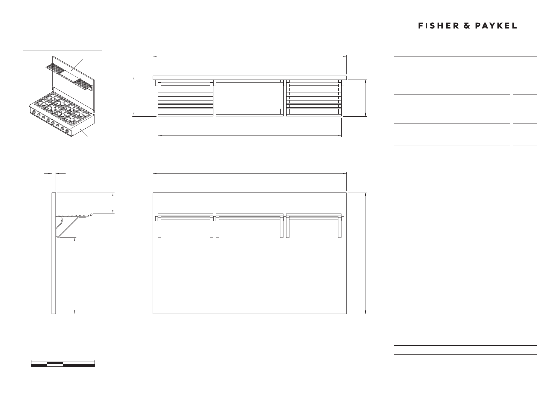
PRODUCT DIMENSIONS
48" Professional Cooktop Backguard
0 100 200 400
millimetres
1216
B
305
23
A
FRONT VIEW
PLAN VIEW
c
DATUM : BOTTOM OF PRODUCT
DATUM : BACK OF PRODUCT
DATUM : BACK OF PRODUCT
BGCV2-1248
CPV2-488NOT TO SCALE
PROFILE VIEW
Model no:
BGCV2-1248
Product Dimensions
mm
A Overall height of backguard
305
B Overall width of backguard
1216
C Overall depth of backguard
23

DATE: 24.04.2018
IMPORTANT: Throughout this guide, dimensions may vary by ±2mm (1/16'').
Read the installation manual for detailed information on installing the product.
For full installation instructions and specifications visit fisherpaykel.com
INDICATES PRODUCT DATUM -------------------------------------------
PRODUCT DIMENSIONS
48" Professional Cooktop Backguard
A
f
e
h
g
i
FRONT VIEW
PLAN VIEW
PROFILE VIEW
c
DATUM : BOTTOM OF PRODUCT
DATUM : BACK OF PRODUCT
DATUM : BACK OF PRODUCT
d
BGCV2-3048
CPV2-488
NOT TO SCALE
0 100 200 400
millimetres
1216
B
1216
B
762
23
Model no:
BGCV2-3048
Product Dimensions
mm
A Overall height of backguard
762
B Overall width of backguard
1216
C Overall depth of backguard and racks
248
D Depth of backguard
23
E Depth of racks
224
F Width of racks
1153
G Distance from top of backguard to bottom of racks
278
H Distance from bottom of backguard to bottom of racks
484
I Distance from top of backguard to top of brackets
150
DATE: 24.04.2018
IMPORTANT: Throughout this guide, dimensions may vary by ±2mm (1/16'').
Read the installation manual for detailed information on installing the product.
For full installation instructions and specifications visit fisherpaykel.com
INDICATES PRODUCT DATUM -------------------------------------------
PRODUCT DIMENSIONS
48" Professional Cooktop Backguard
0 100 200 400
millimetres
1216
B
1216
B
762
23
A
f
e
h
g
FRONT VIEW
PLAN VIEW
PROFILE VIEW
c
DATUM : BOTTOM OF PRODUCT
DATUM : BACK OF PRODUCT
DATUM : BACK OF PRODUCT
d
BGCV2-3048H
CPV2-488
NOT TO SCALE
Model no:
BGCV2-3048H
Product Dimensions
mm
A Overall height of backguard
762
B Overall width of backguard
1216
C Overall depth of backguard and racks
254
D Depth of backguard
23
E Depth of racks
230
F Width of racks
1152
G Distance from top of backguard to top of racks
136
H Distance from bottom of backguard to bottom of racks
479

IMPORTANT: The product dimensions and specifications
applyat the date of issue. Under our policy of continuous
product improvement, these dimensions and specifications
may change at any time. Dimensions may vary by ±2mm (1/16").
Please read the installation manual for detailed information
oninstalling the product or visit fisherpaykel.com.
April 2018