CG301D, CG302D, CG451D, CG603D, CG604D,
CG762D, CG903D & CG905D models
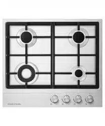
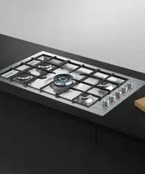
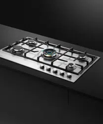
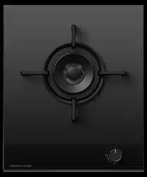
BLACK GAS COOKTOP
INSTALLATION GUIDE
NZ AU UK IE SG

SAFETY AND WARNINGS
SAFETY AND WARNINGS
!
WARNING!
Electric Shock Hazard
Failure to follow this advice may result in
electric shock or death.
• Disconnect the appliance from the mains
electricity supply before carrying out any work
or maintenance.
• Connection to a good earth wiring system is
essential and mandatory.
• Alterations to the domestic wiring system must
only be made by a qualified electrician.
!
WARNING!
Cut Hazard
Failure to use caution could result in injury.
• Take care: some edges are sharp.
READ AND SAVE THIS GUIDE
General Use
z
Read these instructions carefully before installing or using this product.
z
This is a Type A gas appliance.
z
Save these instructions for the local electrical inspector’s use.
z
Installation must comply with your local building and local electricity regulations.
z
This appliance is to be installed and serviced only by Fisher & Paykel trained and supported
service technician or qualified person.
z
The manufacturer accepts no responsibility for the incorrect installation of appliances.
Incorrect installation may result in personal injury, damage to property and may invalidate
any warranty or liability claims.
z
This appliance shall be installed in accordance with the regulations in force and only used
in a well-ventilated space.
z
Packing elements (eg plastic bags, polystyrene foam, staples, packing straps etc) and tools
should not be left around during and after installation, especially if they are within easy
reach of children, as these may cause serious injuries.
z
Make sure you recycle the packaging material.
z
Before disposing of any appliance, make sure that it can no longer be used and that all
hazardous parts are removed or made harmless, so that children playing with the old
appliance cannot harm themselves.
z
Only genuine replacement parts may be used for servicing the appliance. These are
available from your nearest Fisher & Paykel Service Centre.
z
The adjustment conditions for this appliance are stated on the data plate. Prior to
installation, ensure that the local distribution conditions (nature of the gas and gas
pressure) and the adjustment of the appliance are compatible. If in doubt, refer to the local
gas network operator or gas supplier to confirm gas type at installation site.
z
Do not modify this appliance.
z
Do not use or store flammable materials on or near this appliance.
z
Do not spray aerosols in the vicinity of this appliance while it is in operation.
z
You must remove the transit screws before installing the cooktop.
z
Particular attention shall be given to the relevant requirements regarding ventilation.
NZ AU only
z
These appliances are registered in: New Zealand at www.energysafety.govt.nz
z
and Australian Gas Association at www.aga.asn.au.
UK IE only
Ventilation requirements
z
The appliance should be installed in a room or space with an air supply in accordance with
BS 5440:2 2009.
z
For rooms with a volume of less than 5m3, permanent ventilation through a free area of at
least 100cm2 will be required.
z
For rooms with a volume between 5m3 and 10m3, permanent ventilation through a free area
of at least 50cm2 will be required, unless the room has a door which opens directly to the
outside air, in which case no permanent ventilation is required.
z
For rooms with a volume greater than 10m3, no permanent ventilation is required.
z
This appliance is not connected to a combustion products evacuation device. It shall be
installed and connected in accordance with current installation regulations. Particular
attention shall be given to the relevant requirements regarding ventilation.
IMPORTANT!
z
Regardless of room size, all rooms containing the appliance must have direct access to the
outside air via an openable window or equivalent.
z
Where there are other fuel-burning appliances in the same room, BS 5440-2: 2009 should
be consulted to determine the correct amount of free area ventilation requirements.
z
The above requirements also allow for use of a gas oven and grill, but you need to consult
a qualified engineer if there are other gas-burning appliances in the same room.
3
Prior to installing your cooktop, ensure:
z
the local distribution conditions (nature of gas and pressure) and the adjustment of the
appliance are compatible. For adjustment conditions for this appliance see ‘Gas rate
summary’.
z
a suitable disconnection switch is incorporated in the permanent wiring, mounted and
positioned to comply with the local wiring rules and regulations. A means of disconnection
with at least a 3mm air gap contact separation in all poles must be incorporated into the
fixed wiring in accordance with the wiring rules, unless the local wiring rules allow for
alternative means.
z
the appliance is connected to a 220V – 240V 50Hz (10 A) power supply only and earthed
via the power supply cable.
z
there is a power outlet within reach of the power supply cable (900mm from the centre
rear of the product). This must be accessible after installation. The power supply cable
should not touch any metal parts.
z
If the supply cord is damaged, it must be replaced by a special cord or assembly available
from authorised Fisher & Paykel Service Agents.
z
the supply connection point (gas shut-off valve) is accessible after installation.
z
the benchtop is made of a heat-resistant material.
z
Seal exposed bare edges of the cutout with an oil-based paint or moisture-proof
polyurethane to prevent possible moisture creeping between the cooktop trim and
the benchtop.
z
Take extreme care not to chip, crack, or break the top glass surfaces during installation.
A heavy metal tool or part accidentally dropped on the glass could damage it.
z
If, after following the instructions given, correct performance cannot be achieved, please
contact your nearest Fisher & Paykel Authorised Service Centre, Customer Care, or contact
us through our local website listed at the end of this document.
NZ AU only
z
The installation complies with all the requirements of current Australian and New Zealand
Gas Installation Standards (AS/NZS 5601.1), including that the product has to be installed
so that the surface temperature of any nearby combustible surface will not exceed 65°C
above ambient. Refer to 'Clearances'.
z
If installed with an approved flexible hose, the hose must not come in contact with the
bottom of the appliance or any sharp edges. Flexible hose assemblies must be AS/NZS
1869 Class B or Class D certified with a maximum length of 1.20m.
UK and Europe
z
If installed with an approved flexible hose, the hose must not come in contact with
the bottom of the appliance or any sharp edges. Flexible hose assemblies must have a
maximum length of 1.20m.
If you need further assistance, call us on 08000 886 605. Alternatively, contact us at our
office address:
Fisher & Paykel Appliances
420 Cob Drive
Swan Valley
NORTHAMPTON NN4 9BB
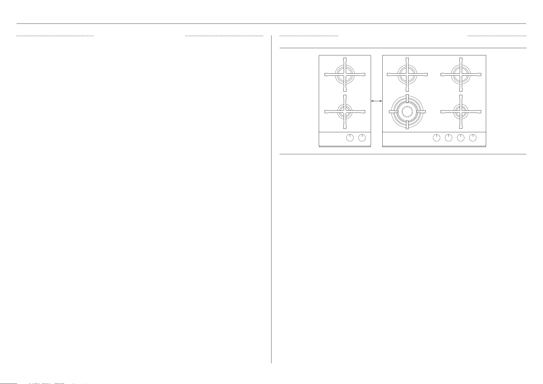
We recommend installing products in separate cutouts with a minimum distance of 5mm
between the glass edges. If installing multiple products within the same cutout adjacent to
each other, a joining strip kit is required. This kit creates a non-visual, structural join between
the two cooktops that ensures the weight of both cooktops is sufficiently supported. Joining
strip kits (PN 534731) can be purchased separately through an authorised Fisher & Paykel
dealer. Visit fisherpaykel.com for more information.
The minimum clearance measurements for different products may vary. Always use the greater
distance when pairing different products (eg an induction model and wok burner model).
5mm
INITIAL CONSIDERATIONS
PRIOR TO INSTALLATION MULTIPLE PRODUCT INSTALLATION
4
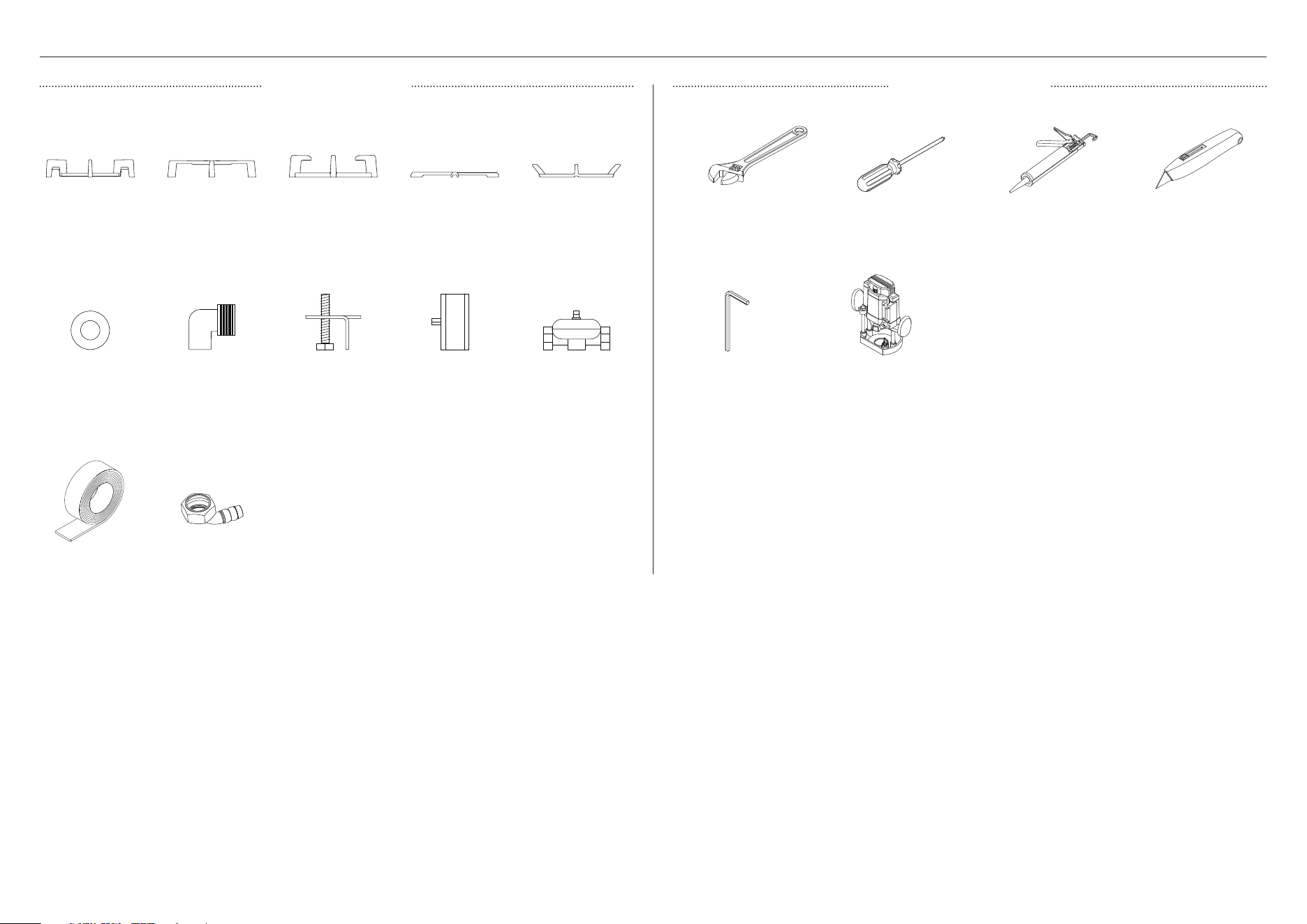
COMPONENTS REQUIRED
Dual wok pan
support*
Wrench
*Some models only
Fibre washer
Hex key
Pan support*
Crosshead
screwdriver
Elbow 1/2" BSP
external thread
Router
Mini wok pan
support*
Silicone
Clamping
brackets
Cutter
Small pan
support*
ULPG test
point adapter*
Wok stand*
NG regulator*
Foam tape
PARTS SUPPLIED TOOLS REQUIRED
Gas elbow (1)
5
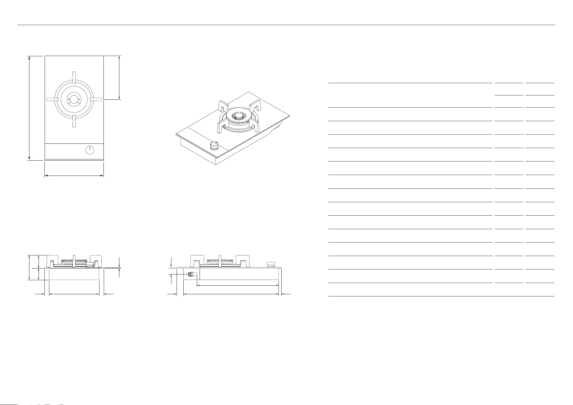
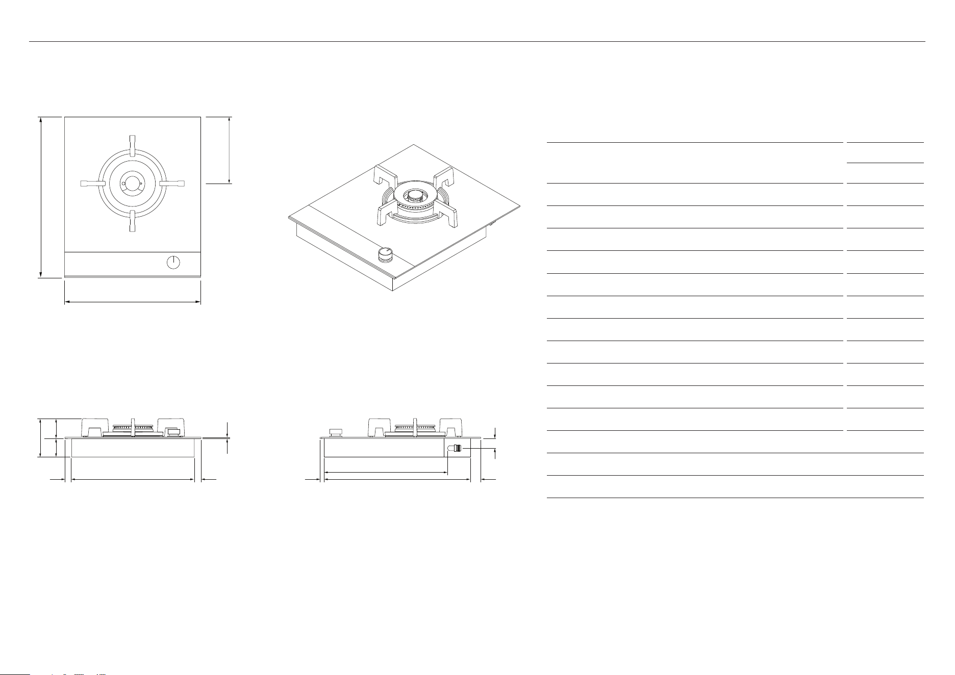
PRODUCT DIMENSIONS — 300MM MODELS
PRODUCT DIMENSIONS
CG301 CG302
MM MM
A Overall height of cooktop* 124 108
B Overall width of cooktop 300 300
C Overall depth of cooktop 530 530
D Height of chassis 58 58
E Width of chassis 254 254
F Depth of chassis 485 485
G Height of cooktop glass and flange 5 5
H Depth of front overhang of cooktop glass 11 11
I Depth of rear overhang of cooktop glass** 34 34
J Depth of side overhang of cooktop glass** 22 22
K Height of tallest trivet*** 66 50
L Distance from centre of rear burner to rear of cooktop 219 112
M Height from benchtop to centre of gas inlet* 32 32
N Depth from front of chassis to gas inlet* 465 465
Note: CG301 illustrated. Profile view showing left side of cooktop.
* Including tallest trivet
** Including flange
*** From bottom of cooktop glass
Actual product dimensions may vary by ± 2 mm
FRONT
PLAN ISOMETRIC
PROFILE
c
l
B
I
M
F
N
H
A
D
g
k
E jj
6
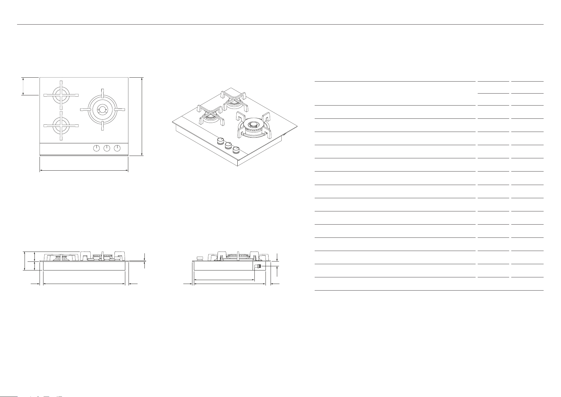
PRODUCT DIMENSIONS — 450MM MODELS
Actual product dimensions may vary by ± 2 mm
FRONT
PLAN ISOMETRIC
PROFILE
A
D
g
k
E F
n
i
m
PRODUCT DIMENSIONS
CG451
MM
A Overall height of cooktop* 124
B Overall width of cooktop 450
C Overall depth of cooktop 530
D Height of chassis 58
E Width of chassis 404
F Depth of chassis 485
G Height of cooktop glass and flange 5
H Depth of front overhang of cooktop glass 11
I Depth of rear overhang of cooktop glass** 34
J Depth of side overhang of cooktop glass** 22
K Height of tallest trivet*** 66
L Distance from centre of rear burner to rear of cooktop 216
M Height from benchtop to centre of gas inlet* 32
N Depth from front of chassis to gas inlet* 483
* Including tallest trivet
** Including flange
*** From bottom of cooktop glass
jj h
c
l
B
7
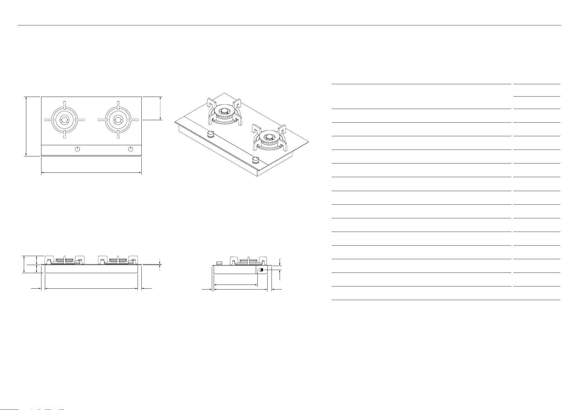
PRODUCT DIMENSIONS — 600MM MODELS
Actual product dimensions may vary by ± 2 mm
PLAN ISOMETRIC
PROFILE
F
n
m
ih
PRODUCT DIMENSIONS
CG603D CG604D
MM MM
A Overall height of cooktop* 124 116
B Overall width of cooktop 600 600
C Overall depth of cooktop 530 530
D Height of chassis 58 58
E Width of chassis 554 554
F Depth of chassis 485 485
G Height of cooktop glass and flange 5 5
H Depth of front overhang of cooktop glass 11 11
I Depth of rear overhang of cooktop glass** 34 34
J Depth of side overhang of cooktop glass** 23 23
K Height of tallest trivet*** 66 58
L Distance from centre of rear burner to rear of cooktop 112 112
M Height from benchtop to centre of gas inlet* 32 32
N Depth from front of chassis to gas inlet* 409 409
Note: CG603 illustrated.
* Including tallest trivet
** Including flange
*** From bottom of cooktop glass
FRONT
A
D
k
g
E
jj
L
B
C
8
PRODUCT DIMENSIONS — 760MM MODELS
Actual product dimensions may vary by ± 2 mm
FRONT
PLAN ISOMETRIC
PROFILE
A
D
k
G
C
B
E
F
N
M
i
PRODUCT DIMENSIONS
CG762D
MM
A Overall height of cooktop* 124
B Overall width of cooktop 760
C Overall depth of cooktop 450
D Height of chassis 58
E Width of chassis 704
F Depth of chassis 405
G Height of cooktop glass and flange 5
H Depth of front overhang of cooktop glass 11
I Depth of rear overhang of cooktop glass** 34
J Depth of side overhang of cooktop glass** 27
K Height of tallest trivet*** 66
L Distance from centre of rear burner to rear of cooktop 176
M Height from benchtop to centre of gas inlet 32
N Depth from front of chassis to gas inlet* 329
* Including tallest trivet
** Including flange
*** From bottom of cooktop glass
h
jj
L
9
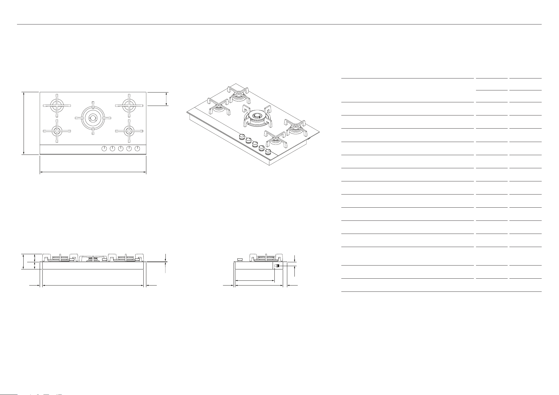
PRODUCT DIMENSIONS — 900MM MODELS
FRONT
PLAN ISOMETRIC
PROFILE
Actual product dimensions may vary by ± 2 mm
A
D
K
G
E JJ FH
N
M
I
PRODUCT DIMENSIONS
CG903D CG905D
MM MM
A Overall height of cooktop* 124 124
B Overall width of cooktop 900 900
C Overall depth of cooktop 450 530
D Height of chassis 58 58
E Width of chassis 854 854
F Depth of chassis 405 485
G Height of cooktop glass and flange 5 5
H Depth of front overhang of cooktop glass 11 11
I Depth of rear overhang of cooktop glass** 34 34
J Depth of side overhang of cooktop glass** 22 22
K Height of tallest trivet*** 66 66
L Distance from centre of rear burner to rear
of cooktop
176 112
M Height from benchtop to centre of gas inlet* 30 30
N Depth from front of chassis to gas inlet* 332 332
Note: CG905 illustrated.
* Including tallest trivet
** Including flange
*** From bottom of cooktop glass
C
L
B
10
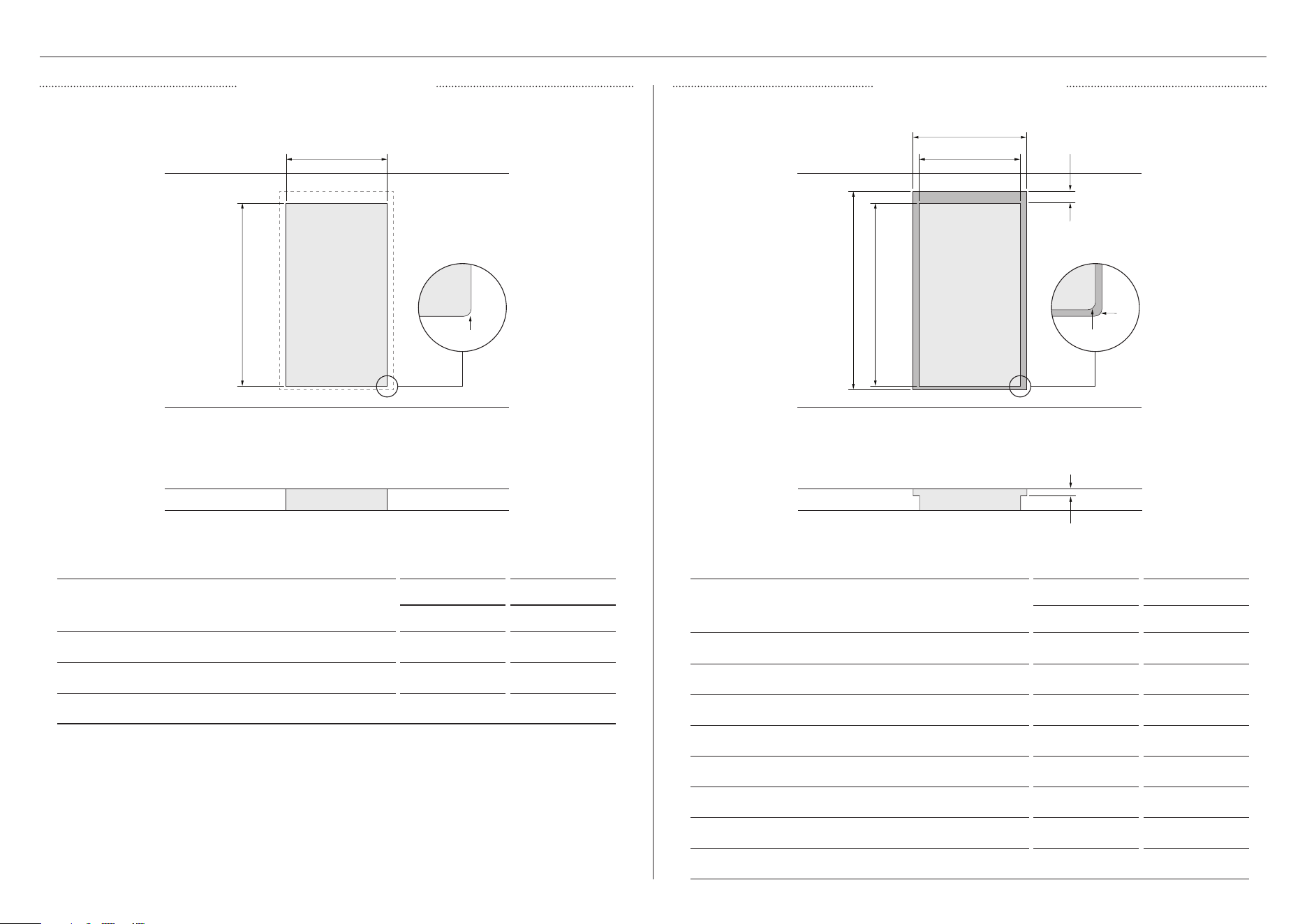
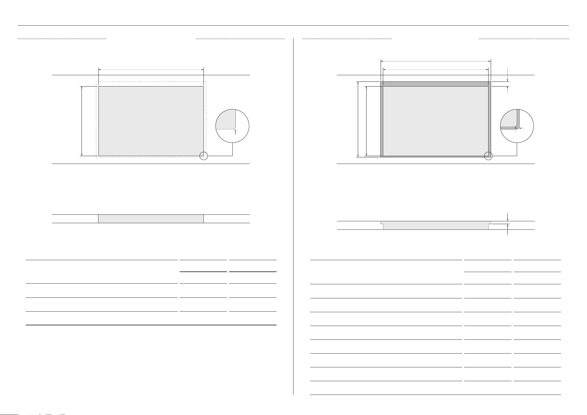
CUTOUT DIMENSIONS — 300MM MODELS
CUTOUT DIMENSIONS
CG301D CG302D
MM MM
A Overall width of cutout 260 260
B Overall depth of cutout 490 490
C Corner radius of cutout max 10 max 10
CUTOUT DIMENSIONS
CG301D CG302D
MM MM
A Overall width of routered recess 305 305
B Overall depth of routered recess 535 535
C Offset overhang allowance 34 34
D Height of routered recess 5 5
E Width of cutout 260 260
F Depth of cutout 490 490
G Corner radius of routered recess max 2 max 2
H Corner radius of cutout max 10 max 10
FRONT FRONT
PLAN PLAN
B fB
A E
A
C H
G
C
D
PROUD INSTALLATION FLUSH INSTALLATION
11
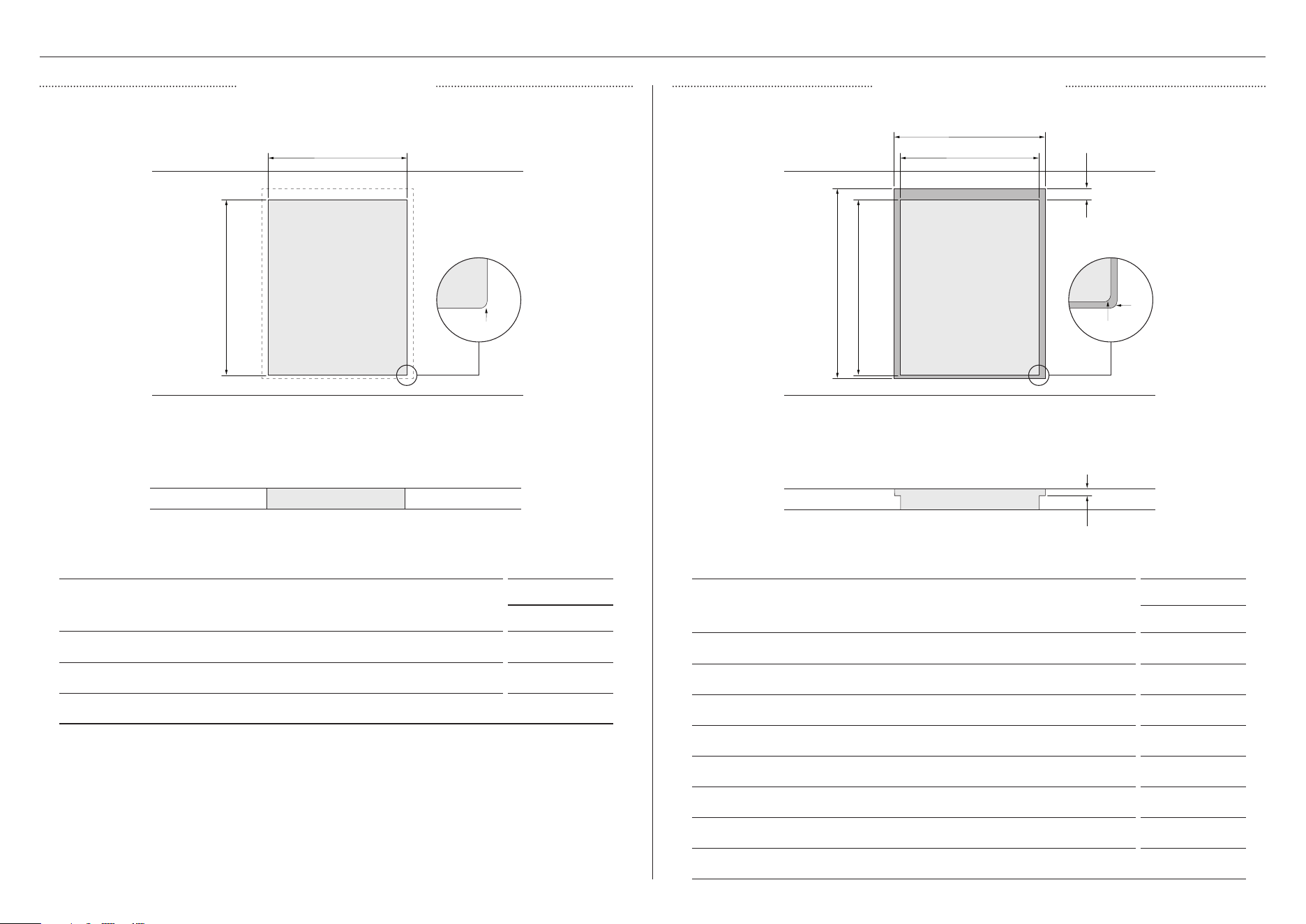
CUTOUT DIMENSIONS — 450MM MODELS
CUTOUT DIMENSIONS
CG451D
MM
A Overall width of cutout 415
B Overall depth of cutout 490
C Corner radius of cutout max 10
CUTOUT DIMENSIONS
CG451D
MM
A Overall width of routered recess 455
B Overall depth of routered recess 535
C Offset overhang allowance 34
D Height of routered recess 5
E Width of cutout 415
F Depth of cutout 490
G Corner radius of routered recess max 2
H Corner radius of cutout max 10
FRONT FRONT
PLAN PLAN
B
fB
A
E
A
C
H
G
C
D
PROUD INSTALLATION FLUSH INSTALLATION
12
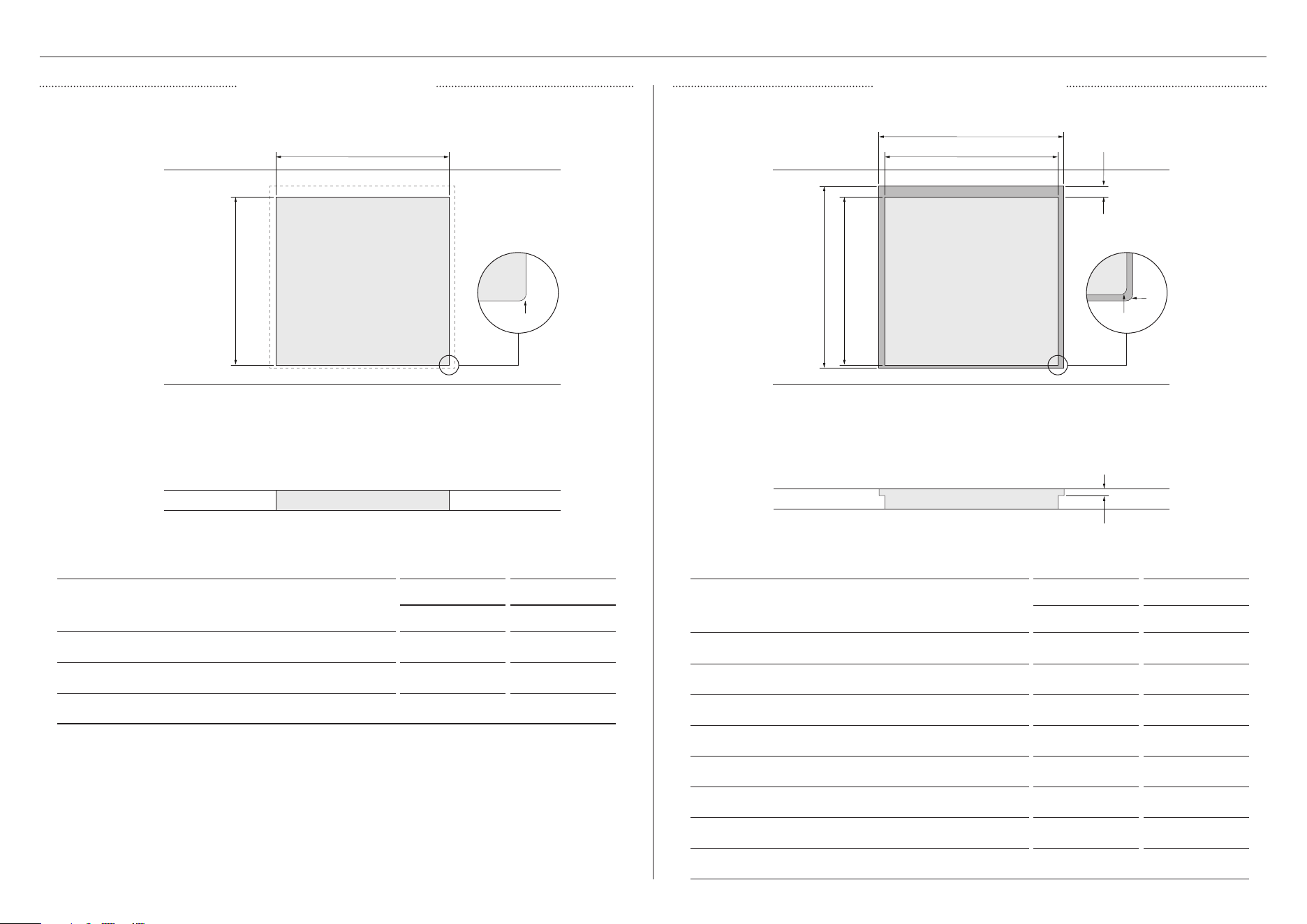
CUTOUT DIMENSIONS — 600MM MODELS
CUTOUT DIMENSIONS
CG603D CG604D
MM MM
A Overall width of cutout 560 560
B Overall depth of cutout 490 490
C Corner radius of cutout max 10 max 10
CUTOUT DIMENSIONS
CG603D CG604D
MM MM
A Overall width of routered recess 605 605
B Overall depth of routered recess 535 535
C Offset overhang allowance 34 34
D Height of routered recess 5 5
E Width of cutout 560 560
F Depth of cutout 490 490
G Corner radius of routered recess max 2 max 2
H Corner radius of cutout max 10 max 10
FRONT FRONT
PLAN PLAN
B
fB
A E
A
C
H
G
C
D
PROUD INSTALLATION FLUSH INSTALLATION
13
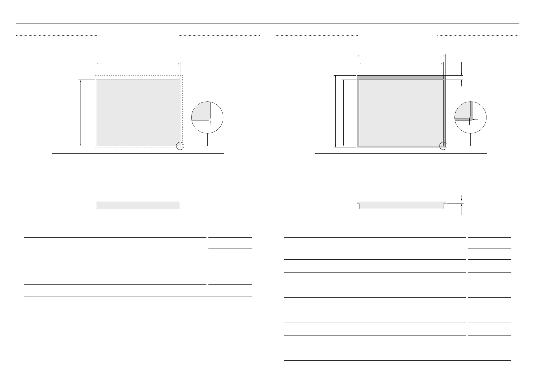
CUTOUT DIMENSIONS — 760MM MODELS
CUTOUT DIMENSIONS
CG762D
MM
A Overall width of cutout 715
B Overall depth of cutout 410
C Corner radius of cutout max 10
CUTOUT DIMENSIONS
CG762D
MM
A Overall width of routered recess 765
B Overall depth of routered recess 455
C Offset overhang allowance 34
D Height of routered recess 5
E Width of cutout 715
F Depth of cutout 410
G Corner radius of routered recess max 2
H Corner radius of cutout max 10
FRONT
PLAN
B
A
C
FRONT
PLAN
fB
E
A
H
G
C
D
PROUD INSTALLATION FLUSH INSTALLATION
14
CUTOUT DIMENSIONS — 900MM MODELS
FRONT
PLAN
B
A
C
FRONT
PLAN
fB
E
A
H
G
C
D
CUTOUT DIMENSIONS
CG903D CG905D
MM MM
A Overall width of cutout 865 865
B Overall depth of cutout 410 490
C Corner radius of cutout max 10 max 10
CUTOUT DIMENSIONS
CG903D CG905D
MM MM
A Overall width of routered recess 905 905
B Overall depth of routered recess 455 535
C Offset overhang allowance 34 34
D Height of routered recess 5 5
E Width of cutout 865 865
F Depth of cutout 410 490
G Corner radius of routered recess max 2 max 2
H Corner radius of cutout max 10 max 10
PROUD INSTALLATION FLUSH INSTALLATION
15
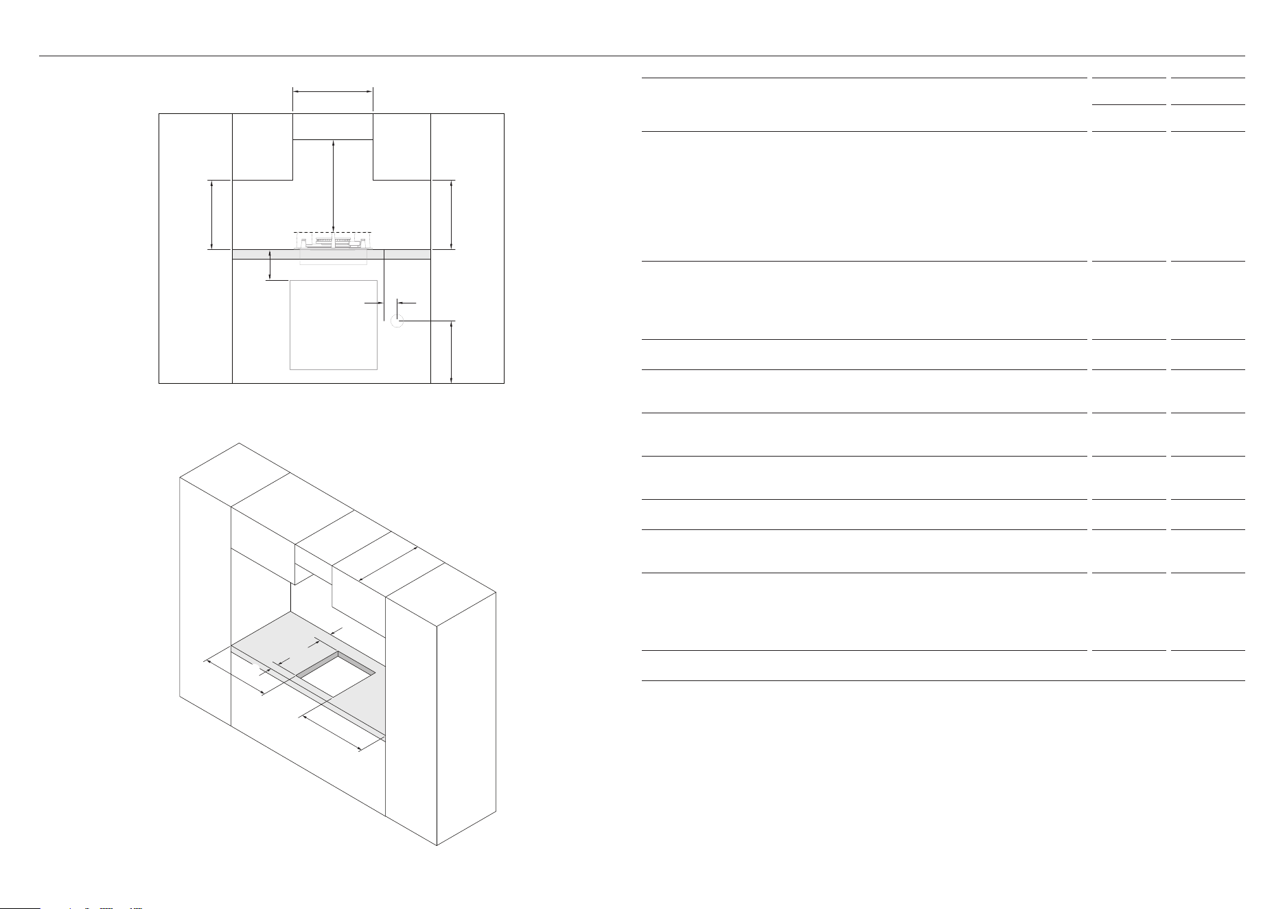
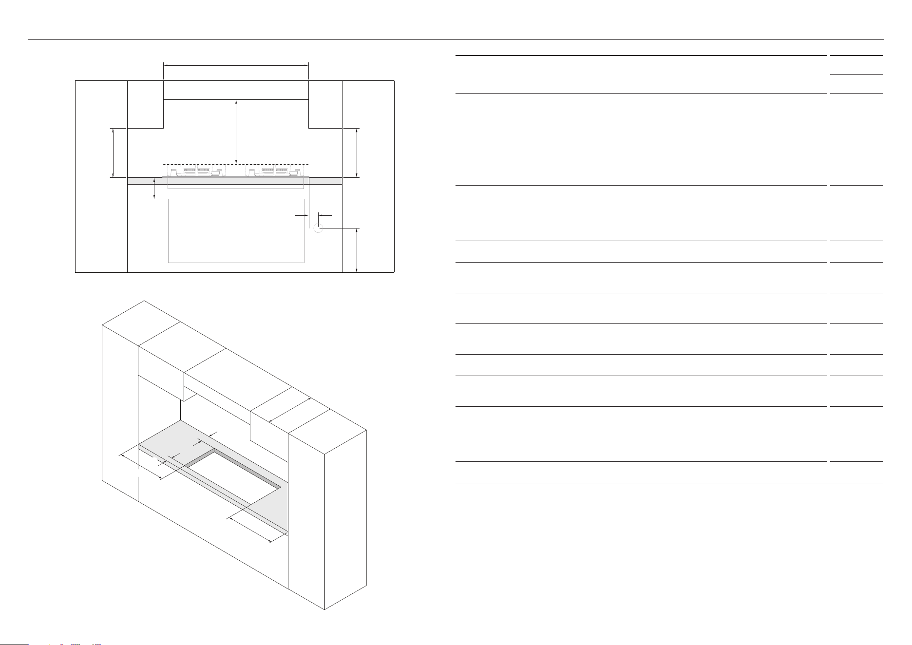
CLEARANCES — 300MM MODELS
A
H
f f
b
D
E
C
C
g
i
j
CLEARANCE DIMENSIONS
CG301D CG302D
MM MM
A Minimum clearance from top of trivets to:
z
Rangehood 650 650
z
Overhead exhaust fan 800 800
z
Downward facing combustible surface* 650 650
z
Downwards-facing tiled or fire resistant surface 500 500
B Minimum clearance below bench top to:
z
Combustible surface 70 70
z
Fisher & Paykel oven or nearest non-combustible surface 65 65
C Minimum clearance from cutout to nearest combustible surface 120 120
D Minimum distance from right edge of cooktop to gas connection
point on wall (if using a flexible hose)
250 250
E Distance from floor to gas connection point on wall
(if using a flexible hose)
800-850 800-850
F Minimum clearance from countertop to overhead cabinet
(not directly above the cooktop)
450 450
G Maximum depth of overhead cabinetry 600 600
H Minimum distance between overhead cabinets
(centered above cooktop)
300 300
I Minimum clearance from rear edge of cutout to nearest:
z
Combustible surface 85 160
z
Non-combustible surface 45 45
J Minimum clearance from front edge of cutout to counter front 35 35
Ensure there is an earthed power outlet within 900mm of the centre rear of the product. The gas
connector on the wall should be accessible with the product installed.
*Combustible surface definition
Any materials of a building structure or decorative structure made of wood, compressed paper,
plant fibres, vinyl/plastic or other materials that are capable of transferring heat or being
ignited and burned. Such material shall be considered combustible even though flame-proofed,
fire-retardant treated or surface-painted, or plastered.
16
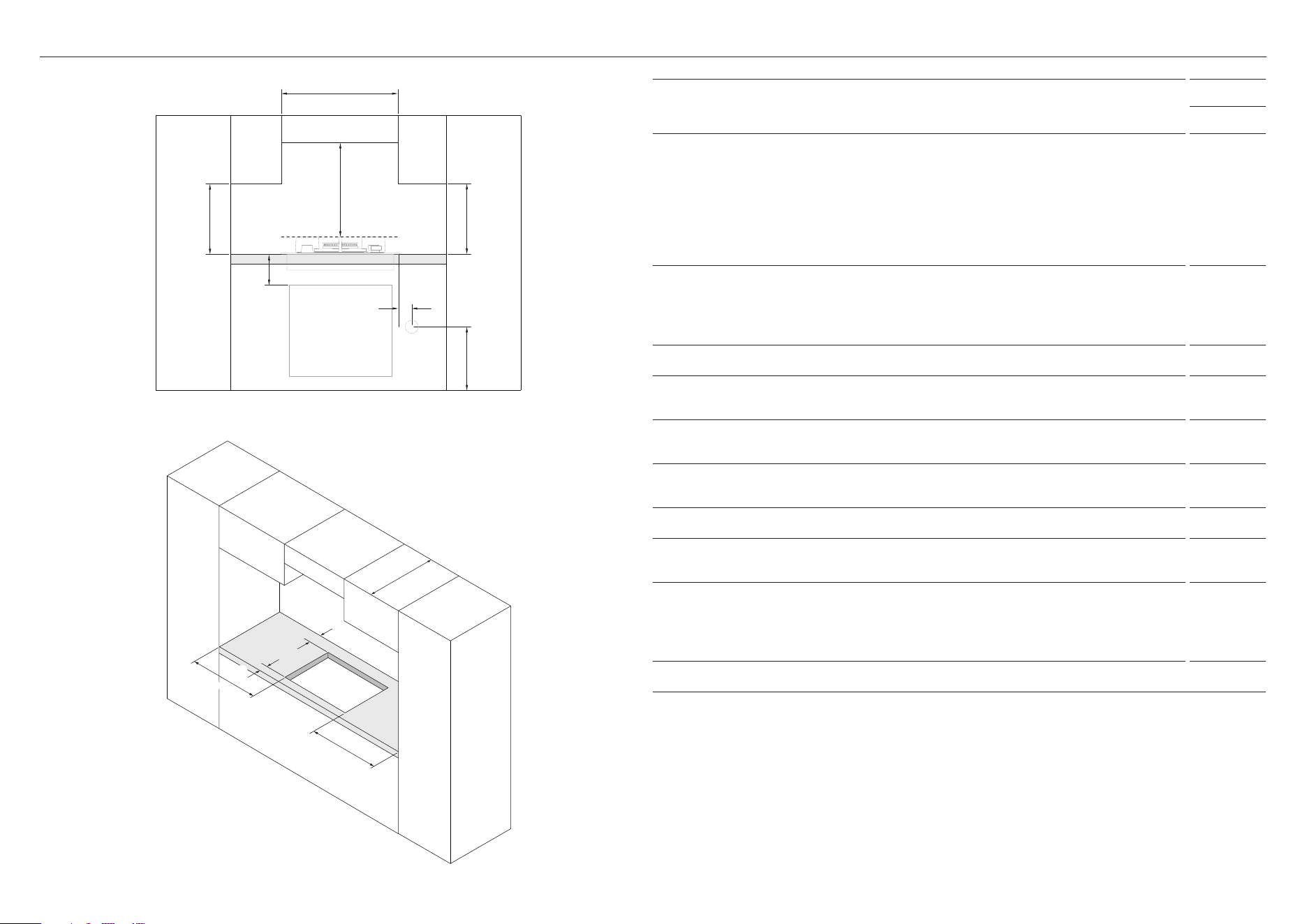
CLEARANCES — 450MM MODELS
CLEARANCE DIMENSIONS
CG451D
MM
A Minimum clearance from top of trivets to:
z
Rangehood 650
z
Overhead exhaust fan 800
z
Downward facing combustible surface* 650
z
Downwards-facing tiled or fire resistant surface 500
B Minimum clearance below bench top to:
z
Combustible surface 70
z
Fisher & Paykel oven or nearest non-combustible surface 65
C Minimum clearance from cutout to nearest combustible surface 60
D Minimum distance from right edge of cooktop to gas connection point on wall
(if using a flexible hose)
250
E Distance from floor to gas connection point on wall
(if using a flexible hose)
800-850
F Minimum clearance from countertop to overhead cabinet
(not directly above the cooktop)
450
G Maximum depth of overhead cabinetry 600
H Minimum distance between overhead cabinets
(centered above cooktop)
450
I Minimum clearance from rear edge of cutout to nearest:
z
Combustible surface 85
z
Non-combustible surface 45
J Minimum clearance from front edge of cutout to counter front 35
Ensure there is an earthed power outlet within 900mm of the centre rear of the product. The gas
connector on the wall should be accessible with the product installed.
*Combustible surface definition
Any materials of a building structure or decorative structure made of wood, compressed paper,
plant fibres, vinyl/plastic or other materials that are capable of transferring heat or being
ignited and burned. Such material shall be considered combustible even though flame-proofed,
fire-retardant treated or surface-painted, or plastered.
A
H
f f
b
D
E
C
C
g
i
j
17
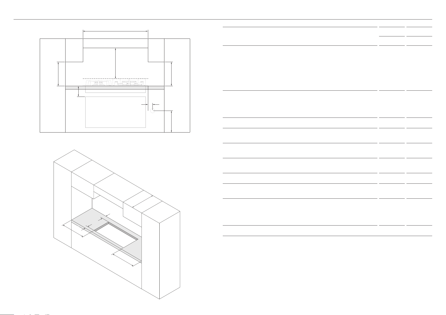
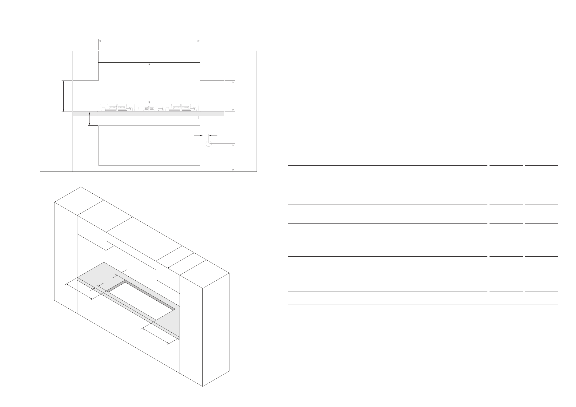
CLEARANCES — 600MM MODELS
CLEARANCE DIMENSIONS
CG603D CG604D
MM MM
A Minimum clearance from top of trivets to:
z
Rangehood 650 650
z
Overhead exhaust fan 800 800
z
Downward facing combustible surface* 650 650
z
Downwards-facing tiled or fire resistant surface 500 500
B Minimum clearance below bench top to:
z
Combustible surface 70 70
z
Fisher & Paykel oven or nearest non-combustible surface 65 65
C Minimum clearance from cutout to nearest combustible surface 115 130
D Minimum distance from right edge of cooktop to gas connection
point on wall (if using a flexible hose)
250 250
E Distance from floor to gas connection point on wall
(if using a flexible hose)
800-850 800-850
F Minimum clearance from countertop to overhead cabinet
(not directly above the cooktop)
450 450
G Maximum depth of overhead cabinetry 600 600
H Minimum distance between overhead cabinets
(centered above cooktop)
600 600
I Minimum clearance from rear edge of cutout to nearest:
z
Combustible surface 160 160
z
Non-combustible surface 45 45
J Minimum clearance from front edge of cutout to counter front 35 35
Ensure there is an earthed power outlet within 900mm of the centre rear of the product. The gas
connector on the wall should be accessible with the product installed.
*Combustible surface definition
Any materials of a building structure or decorative structure made of wood, compressed paper,
plant fibres, vinyl/plastic or other materials that are capable of transferring heat or being
ignited and burned. Such material shall be considered combustible even though flame-proofed,
fire-retardant treated or surface-painted, or plastered.
A
H
f f
b
C
C
D
E
g
i
j
18
CLEARANCES — 760MM MODELS
CLEARANCE DIMENSIONS
CG762D
MM
A Minimum clearance from top of trivets to:
z
Rangehood 650
z
Overhead exhaust fan 800
z
Downward facing combustible surface* 650
z
Downwards-facing tiled or fire resistant surface 500
B Minimum clearance below bench top to:
z
Combustible surface 70
z
Fisher & Paykel oven or nearest non-combustible surface 65
C Minimum clearance from cutout to nearest combustible surface 115
D Minimum distance from right edge of cooktop to gas connection point on wall
(if using a flexible hose)
250
E Distance from floor to gas connection point on wall
(if using a flexible hose)
800-850
F Minimum clearance from countertop to overhead cabinet
(not directly above the cooktop)
450
G Maximum depth of overhead cabinetry 600
H Minimum distance between overhead cabinets
(centered above cooktop)
760
I Minimum clearance from rear edge of cutout to nearest:
z
Combustible surface 125
z
Non-combustible surface 45
J Minimum clearance from front edge of cutout to counter front 35
Ensure there is an earthed power outlet within 900mm of the centre rear of the product. The gas
connector on the wall should be accessible with the product installed.
*Combustible surface definition
Any materials of a building structure or decorative structure made of wood, compressed paper,
plant fibres, vinyl/plastic or other materials that are capable of transferring heat or being
ignited and burned. Such material shall be considered combustible even though flame-proofed,
fire-retardant treated or surface-painted, or plastered.
A
H
f f
b
C
C
D
E
g
i
j
19
CLEARANCES — 900MM MODELS
CLEARANCE DIMENSIONS
CG903D CG905D
MM MM
A Minimum clearance from top of trivets to:
z
Rangehood 650 650
z
Overhead exhaust fan 800 800
z
Downward facing combustible surface* 650 650
z
Downwards-facing tiled or fire resistant surface 500 500
B Minimum clearance below bench top to:
z
Combustible surface 70 70
z
Fisher & Paykel oven or nearest non-combustible surface 65 65
C Minimum clearance from cutout to nearest combustible surface 115 130
D Minimum distance from right edge of cooktop to gas connection
point on wall (if using a flexible hose)
250 250
E Distance from floor to gas connection point on wall
(if using a flexible hose)
800-850 800-850
F Minimum clearance from countertop to overhead cabinet
(not directly above the cooktop)
450 450
G Maximum depth of overhead cabinetry 600 600
H Minimum distance between overhead cabinets
(centered above cooktop)
900 900
I Minimum clearance from rear edge of cutout to nearest:
z
Combustible surface 125 160
z
Non-combustible surface 45 45
J Minimum clearance from front edge of cutout to counter front 35 35
Ensure there is an earthed power outlet within 900mm of the centre rear of the product. The gas
connector on the wall should be accessible with the product installed.
*Combustible surface definition
Any materials of a building structure or decorative structure made of wood, compressed paper,
plant fibres, vinyl/plastic or other materials that are capable of transferring heat or being
ignited and burned. Such material shall be considered combustible even though flame-proofed,
fire-retardant treated or surface-painted, or plastered.
A
H
f f
b
C
C
D
E
g
i
j
20
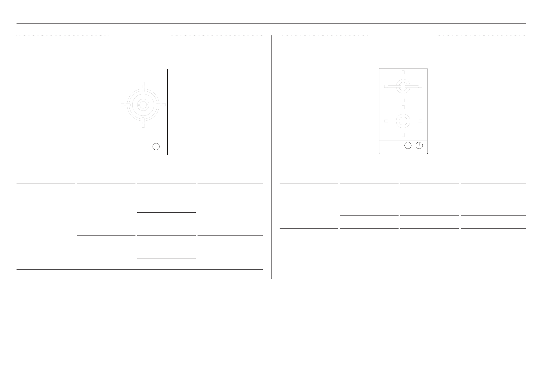
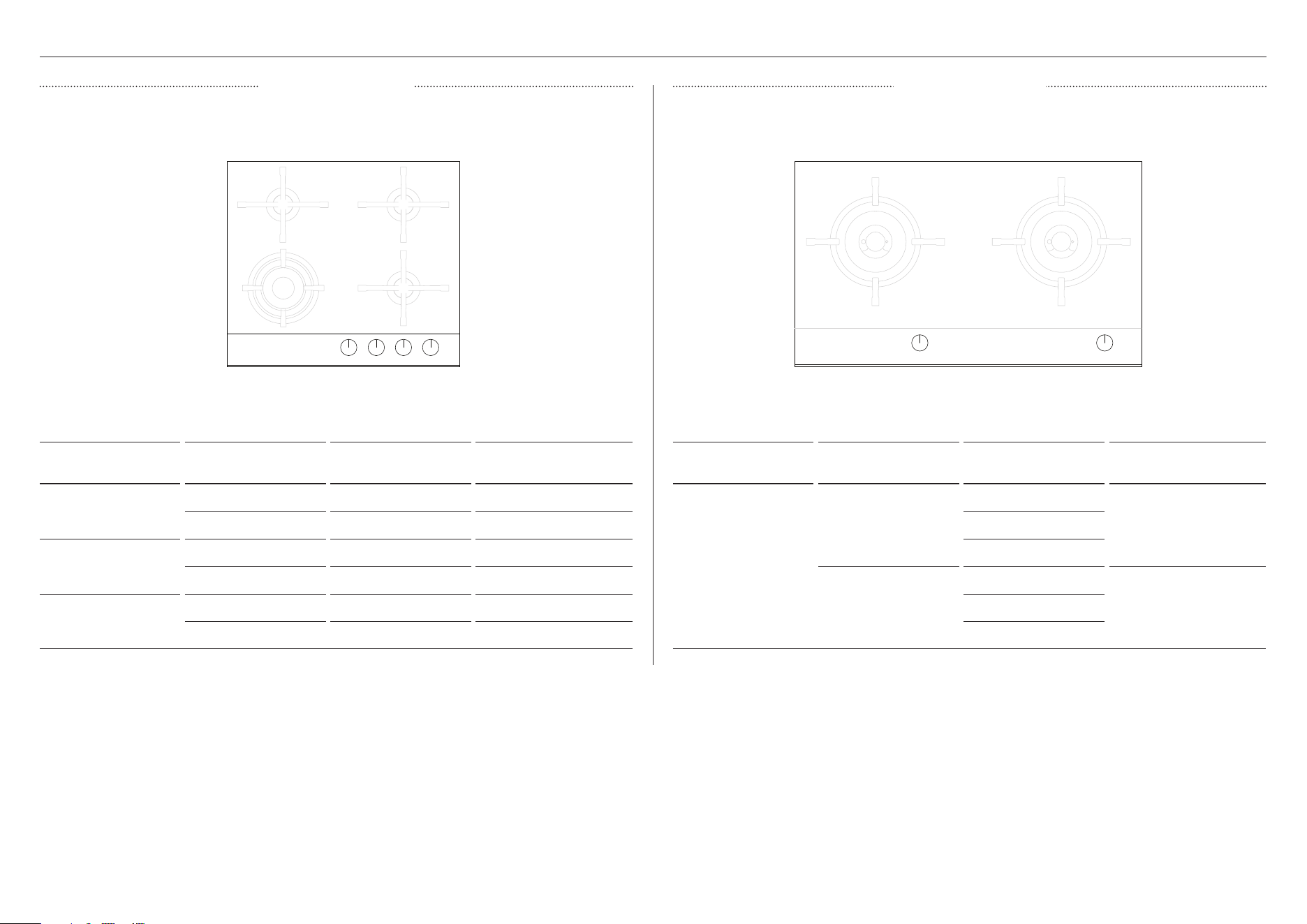
GAS RATE SUMMARY (NZ AU ONLY)
All appliances are factory set for either Natural Gas or ULPG and are not convertible.
Check the ‘Gas type’ sticker on the base of the appliance.
BURNER GAS TYPE
JET SIZE
(MM)
NOMINAL RATING
(MJ/H)
1 Semi-rapid
NG (1.00kPa)* 1.35 8.80
ULPG (2.75kPa)* 0.80 8.10
2 Auxiliary
NG (1.00kPa)* 1.00 5.00
ULPG (2.75kPa)* 0.64 5.00
*Nominal pressure with at least one large burner on high
1
2
1
BURNER GAS TYPE
JET SIZE
(MM)
NOMINAL RATING
(MJ/H)
1 Dual wok
NG (1.00kPa)*
1.45
21.501.45
0.70
ULPG (2.75kPa)*
0.80
20.500.80
0.50
*Nominal pressure with at least one large burner on high
CG301D MODELS CG302D MODELS
21
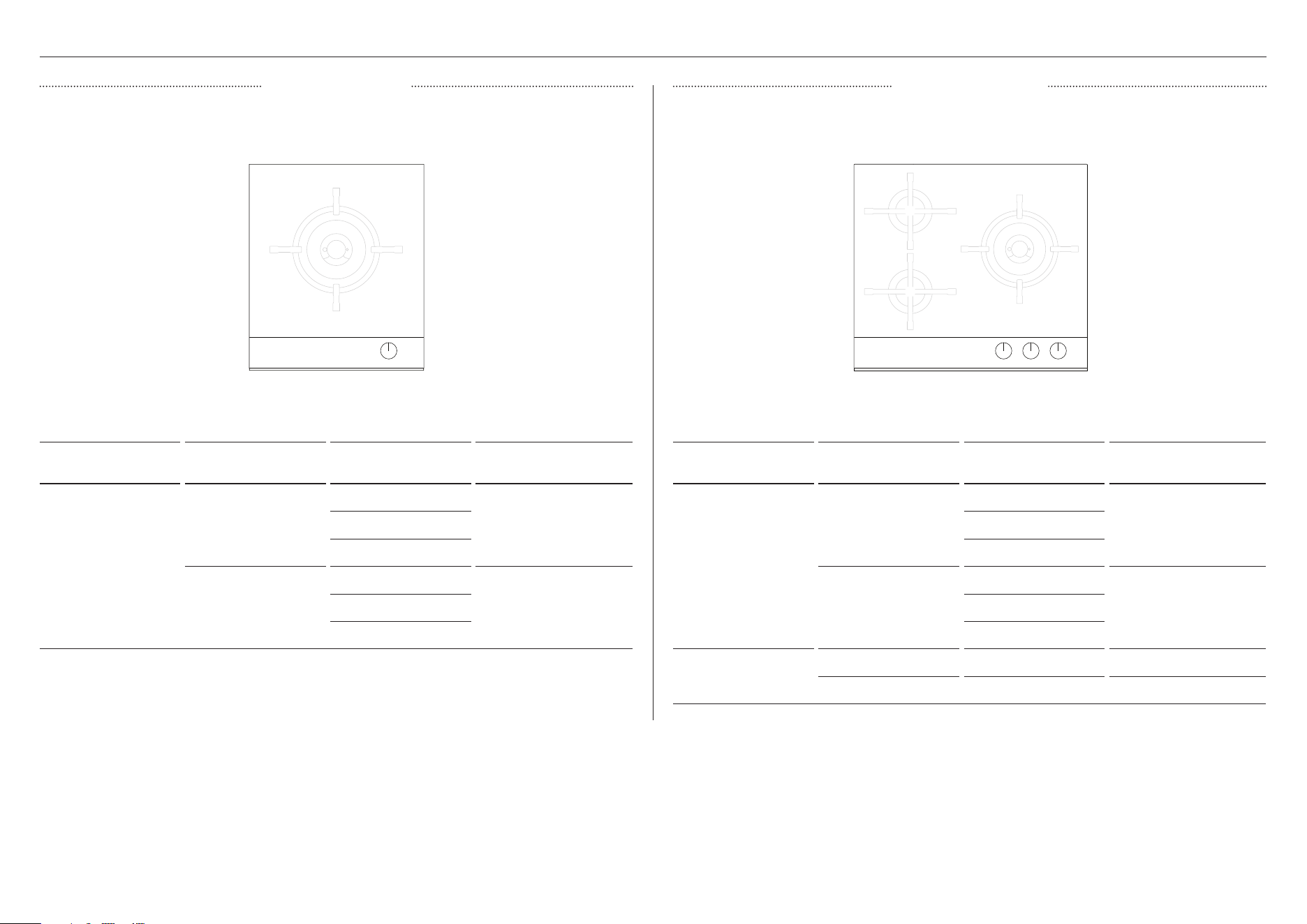
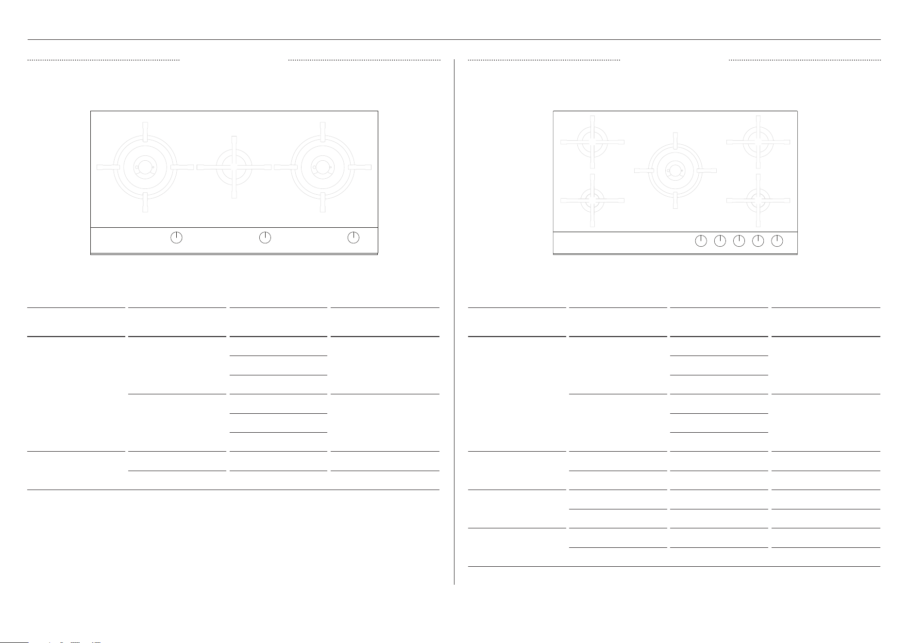
GAS RATE SUMMARY (NZ AU ONLY)
BURNER GAS TYPE
JET SIZE
(MM)
NOMINAL RATING
(MJ/H)
1 Dual wok
NG (1.00kPa)*
1.43
21.01.43
0.70
ULPG (2.75kPa)*
0.80
20.500.80
0.50
*Nominal pressure with at least one large burner on high
BURNER GAS TYPE
JET SIZE
(MM)
NOMINAL RATING
(MJ/H)
1 Dual wok
NG (1.00kPa)*
1.26
16.601.26
0.70
ULPG (2.75kPa)*
0.73
16.800.73
0.50
2 Semi-rapid
NG (1.00kPa)* 1.30 8.40
ULPG (2.75kPa)* 0.76 7.50
*Nominal pressure with at least one large burner on high
1
2
2
1
CG451D MODELS CG603D MODELS
22
GAS RATE SUMMARY (NZ AU ONLY)
BURNER GAS TYPE
JET SIZE
(MM)
NOMINAL RATING
(MJ/H)
1 Mini wok
NG (1.00kPa)* 1.55 11.70
ULPG (2.75kPa)* 0.94 11.70
2 Semi-rapid
NG (1.00kPa)* 1.30 8.30
ULPG (2.75kPa)* 0.76 7.50
3 Auxiliary
NG (1.00kPa)* 0.85 3.60
ULPG (2.75kPa)* 0.55 3.60
*Nominal pressure with at least one large burner on high
BURNER GAS TYPE
JET SIZE
(MM)
NOMINAL RATING
(MJ/H)
1 Dual wok
NG (1.00kPa)*
1.30
18.001.30
0.70
ULPG (2.75kPa)*
0.76
18.000.76
0.50
*Nominal pressure with at least one large burner on high
2
1
2
3
1 1
CG604D MODELS CG762D MODELS
23
GAS RATE SUMMARY (NZ AU ONLY)
BURNER GAS TYPE
JET SIZE
(MM)
NOMINAL RATING
(MJ/H)
1 Dual wok
NG (1.00kPa)*
1.30
18.001.30
0.70
ULPG (2.75kPa)*
0.76
18.000.76
0.50
2 Rapid
NG (1.00kPa)* 1.55 11.50
ULPG (2.75kPa)* 0.94 11.50
3 Semi-rapid
NG (1.00kPa)* 1.30 8.30
ULPG (2.75kPa)* 0.76 7.50
4 Auxiliary
NG (1.00kPa)* 0.85 3.60
ULPG (2.75kPa)* 0.55 3.60
*Nominal pressure with at least one large burner on high
BURNER GAS TYPE
JET SIZE
(MM)
NOMINAL RATING
(MJ/H)
1 Dual wok
NG (1.00kPa)*
1.30
18.001.30
0.70
ULPG (2.75kPa)*
0.76
18.000.76
0.50
2 Semi-rapid
NG (1.00kPa)* 1.30 8.30
ULPG (2.75kPa)* 0.76 7.50
*Nominal pressure with at least one large burner on high
1
3 3
2
2
1
4
1
CG903D MODELS CG905D MODELS
24
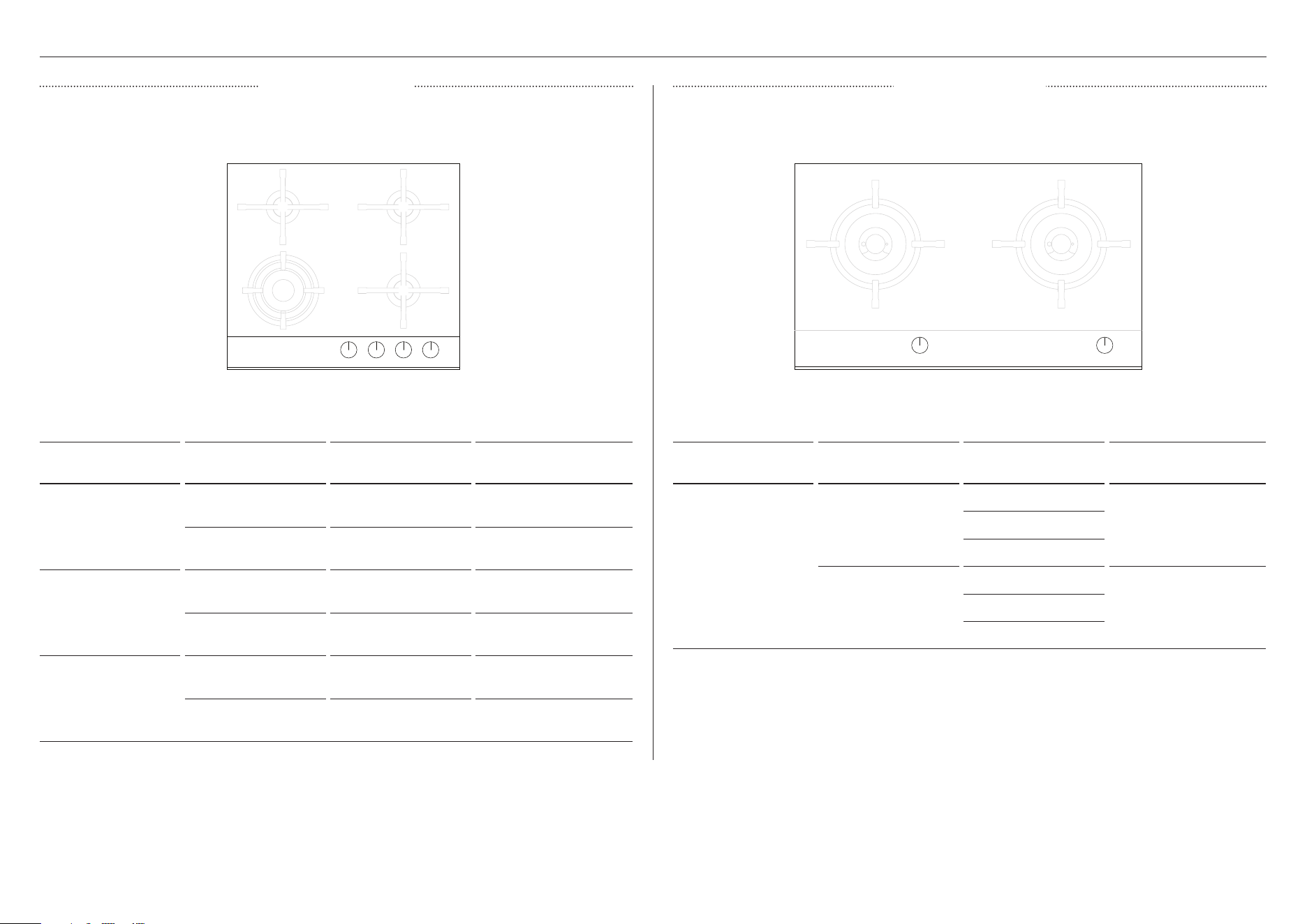
GAS RATE SUMMARY (UK IE ONLY)
All appliances are factory set for either Natural Gas or ULPG and are not convertible.
Check the ‘Gas type’ sticker on the base of the appliance.
BURNER GAS TYPE
JET SIZE
(MM)
NOMINAL RATING
1 Semi-rapid
NG (20mbar)* 1.14
2.30 kW
1978 kCal/h
ULPG
(28 – 30/37 mbar)*
0.76
2.30 kW (167 g/h)
1978 kCal/h
2 Auxiliary
NG (20mbar)* 0.78
1.10 kW
946 kCal/h
ULPG
(28 – 30/37 mbar)*
0.56
1.20 kW
1032 kCal/h (87 g/h)
*Nominal pressure with at least one large burner on high
1
2
1
BURNER GAS TYPE
JET SIZE
(MM)
NOMINAL RATING
1 Dual wok
NG
(20mbar)*
1.25
6.00 kW
5162 kCal/h
1.25
0.71
ULPG
(28 – 30/37 mbar)*
0.80
5.50 kW
4732 kCal/h (395 g/h)0.80
0.50
*Nominal pressure with at least one large burner on high
CG301D MODELS CG302D MODELS
25

GAS RATE SUMMARY (UK IE ONLY)
BURNER GAS TYPE
JET SIZE
(MM)
NOMINAL RATING
1 Dual wok
NG (20mbar)*
1.12
5.00 kW
4299 kCal/h
1.12
0.72
ULPG
(28 – 30/37 mbar)*
0.69
4.50 kW (327 g/h)
3869 kCal/h
0.69
0.50
*Nominal pressure with at least one large burner on high
BURNER GAS TYPE
JET SIZE
(MM)
NOMINAL RATING
1 Dual wok
NG (20mbar)*
1.12
5.00 kW
4299 kCal/h
1.12
0.72
ULPG
(28 – 30/37 mbar)*
0.69
4.50 kW (327 g/h)
3869 kCal/h
0.69
0.50
2 Semi-rapid
NG (20mbar)* 1.14
2.30 kW
1978 kCal/h
ULPG
(28 – 30/37 mbar)*
0.76
2.30 kW (167 g/h)
1978 kCal/h
*Nominal pressure with at least one large burner on high
1
2
2
1
CG451D MODELS CG603D MODELS
26
GAS RATE SUMMARY (UK IE ONLY)
BURNER GAS TYPE
JET SIZE
(MM)
NOMINAL RATING
1 Mini wok
NG (20mbar)* 1.41
3.60 kW
3096 kCal/h
ULPG
(28 – 30/37 mbar)*
0.91
3.20 kW (233 g/h)
2752 kCal/h
2 Semi-rapid
NG (20mbar)* 1.14
2.30 kW
1978 kCal/h
ULPG
(28 – 30/37 mbar)*
0.76
2.30 kW (167 g/h)
1978 kCal/h
3 Auxiliary
NG (20mbar)* 0.78
1.10 kW
946 kCal/h
ULPG
(28 – 30/37 mbar)*
0.56
1.20 kW
1032 kCal/h (87 g/h)
*Nominal pressure with at least one large burner on high
BURNER GAS TYPE
JET SIZE
(MM)
NOMINAL RATING
1 Dual wok
NG (20mbar)*
1.12
5.00 kW
4299 kCal/h
1.12
0.72
ULPG
(28 – 30/37 mbar)*
0.69
4.50 kW (327 g/h)
3869 kCal/h
0.69
0.50
*Nominal pressure with at least one large burner on high
2
1
2
3
1 1
CG604D MODELS CG762D MODELS
27
GAS RATE SUMMARY (UK IE ONLY)
BURNER GAS TYPE
JET SIZE
(MM)
NOMINAL RATING
1 Dual wok
NG (20mbar)*
1.12
5.00 kW
4299 kCal/h
1.12
0.72
ULPG
(28 – 30/37 mbar)*
0.69
4.50 kW (327 g/h)
3869 kCal/h
0.69
0.50
2 Rapid
NG (20mbar)* 1.37
3.90 kW
3353 kCal/h
ULPG
(28 – 30/37 mbar)*
0.96
3.90 kW (254g/h)
3010 kCal/h
3 Semi-rapid
NG (20mbar)* 1.14
2.30 kW
1978 kCal/h
ULPG
(28 – 30/37 mbar)*
0.76
2.30 kW (167 g/h)
1978 kCal/h
4 Auxiliary
NG (20mbar)* 0.78
1.10 kW
946 kCal/h
ULPG
(28 – 30/37 mbar)*
0.56
1.20 kW
1032 kCal/h (87 g/h)
*Nominal pressure with at least one large burner on high
BURNER GAS TYPE
JET SIZE
(MM)
NOMINAL RATING
1 Dual wok
NG (20mbar)*
1.12
5.00 kW
4299 kCal/h
1.12
0.72
ULPG
(28 – 30/37 mbar)*
0.69
4.50 kW (327 g/h)
3869 kCal/h
0.69
0.50
2 Semi-rapid
NG (20mbar)* 1.14
2.30 kW
1978 kCal/h
ULPG
(28 – 30/37 mbar)*
0.76
2.30 kW (167 g/h)
1978 kCal/h
*Nominal pressure with at least one large burner on high
1
3 3
2
2
1
4
1
CG903D MODELS CG905D MODELS
28
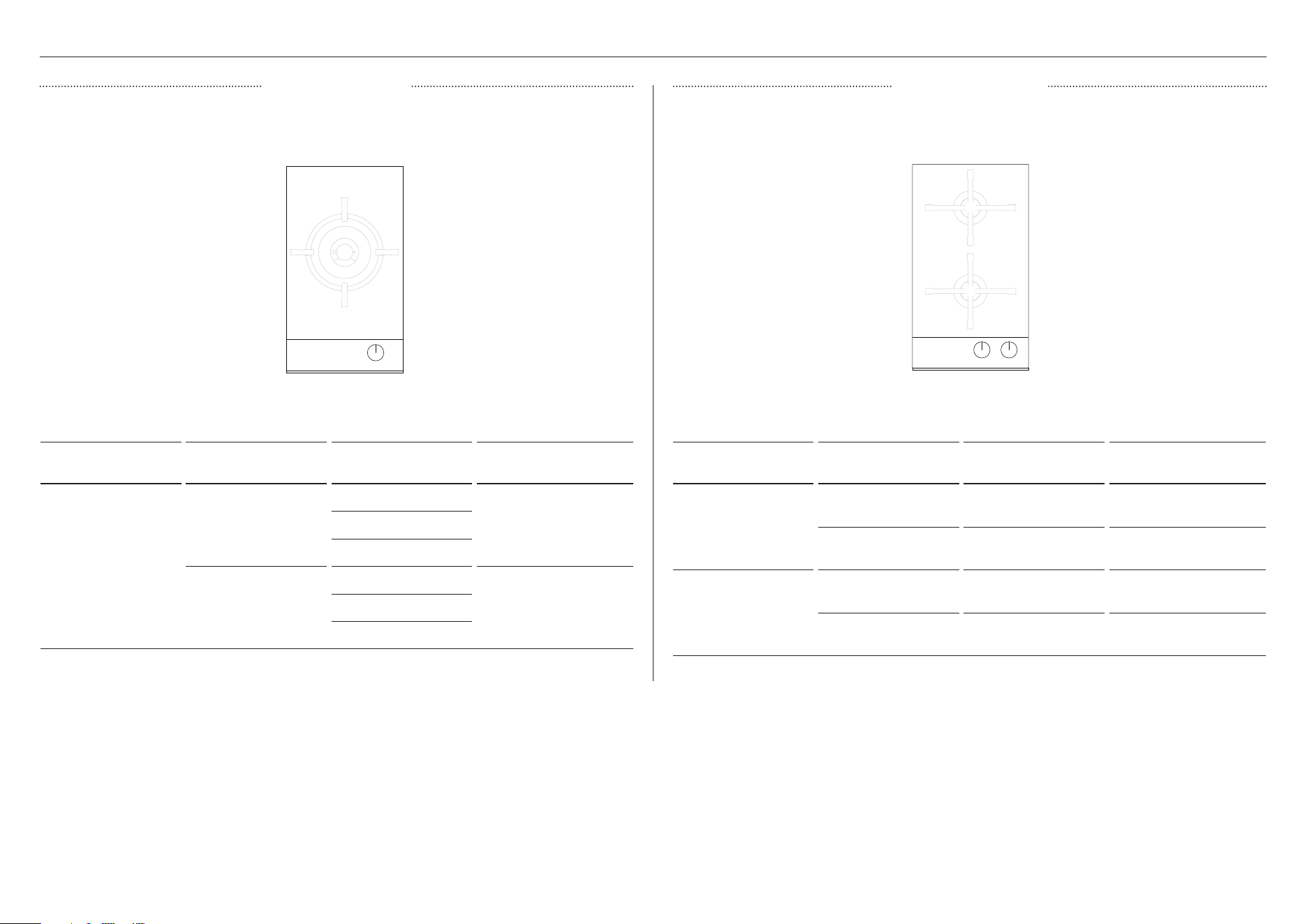
GAS RATE SUMMARY (SG ONLY)
All appliances are factory set for either Natural Gas or ULPG and are not convertible.
Check the ‘Gas type’ sticker on the base of the appliance.
BURNER GAS TYPE
JET SIZE
(MM)
NOMINAL RATING
1 Dual wok
TG (G110)
(0.8 kPa/8 mbar)*
2.50
4.60 kW2.50
1.30
ULPG (G30)
(2.9 kPa/29 mbar)*
0.73
5.00 kW0.73
0.50
*Nominal pressure with one dual wok burner on High.
1
CG451D MODELS
BURNER GAS TYPE
JET SIZE
(MM)
NOMINAL RATING
1 Dual wok
TG (G110) (0.8kPa /
8mbar)*
2.50
4.50kW2.50
1.30
ULPG (G30) (2.9kPa
/ 29mbar)*
0.69
4.50kW0.69
0.50
2 Semi-rapid
TG (G110)
(0.8kPa / 8mbar)*
2.07 2.00kW
ULPG (G30) (2.9kPa
/ 29mbar)*
0.76 2.30kW
*Nominal pressure with at least one large burner on high
2
2
1
CG603D MODELS
29
GAS RATE SUMMARY (SG ONLY)
BURNER GAS TYPE
JET SIZE
(MM)
NOMINAL RATING
1 Dual wok
TG (G110)
(0.8 kPa/8 mbar)*
2.50
4.30 kW2.50
1.30
ULPG (G30)
(2.9 kPa/29 mbar)*
0.73
5.00 kW0.73
0.50
2 Semi-rapid
TG (G110)
(0.8 kPa/8 mbar)*
2.07 2.05 kW
ULPG (G30)
(2.9 kPa/29 mbar)*
0.76 2.28 kW
*Nominal pressure with one dual wok burner on High.
2
1 1
CG903D MODELS
BURNER GAS TYPE
JET SIZE
(MM)
NOMINAL RATING
1 Dual wok
TG (G110)
(0.8 kPa/8 mbar)*
2.50
4.60 kW2.50
1.30
ULPG (G30)
(2.9 kPa/29 mbar)*
0.73
5.00 kW0.73
0.50
*Nominal pressure with at least one large burner on high
1 1
CG762D MODELS
30
2 5
1 4
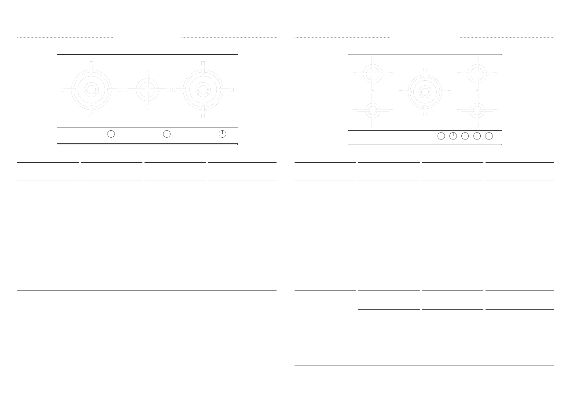
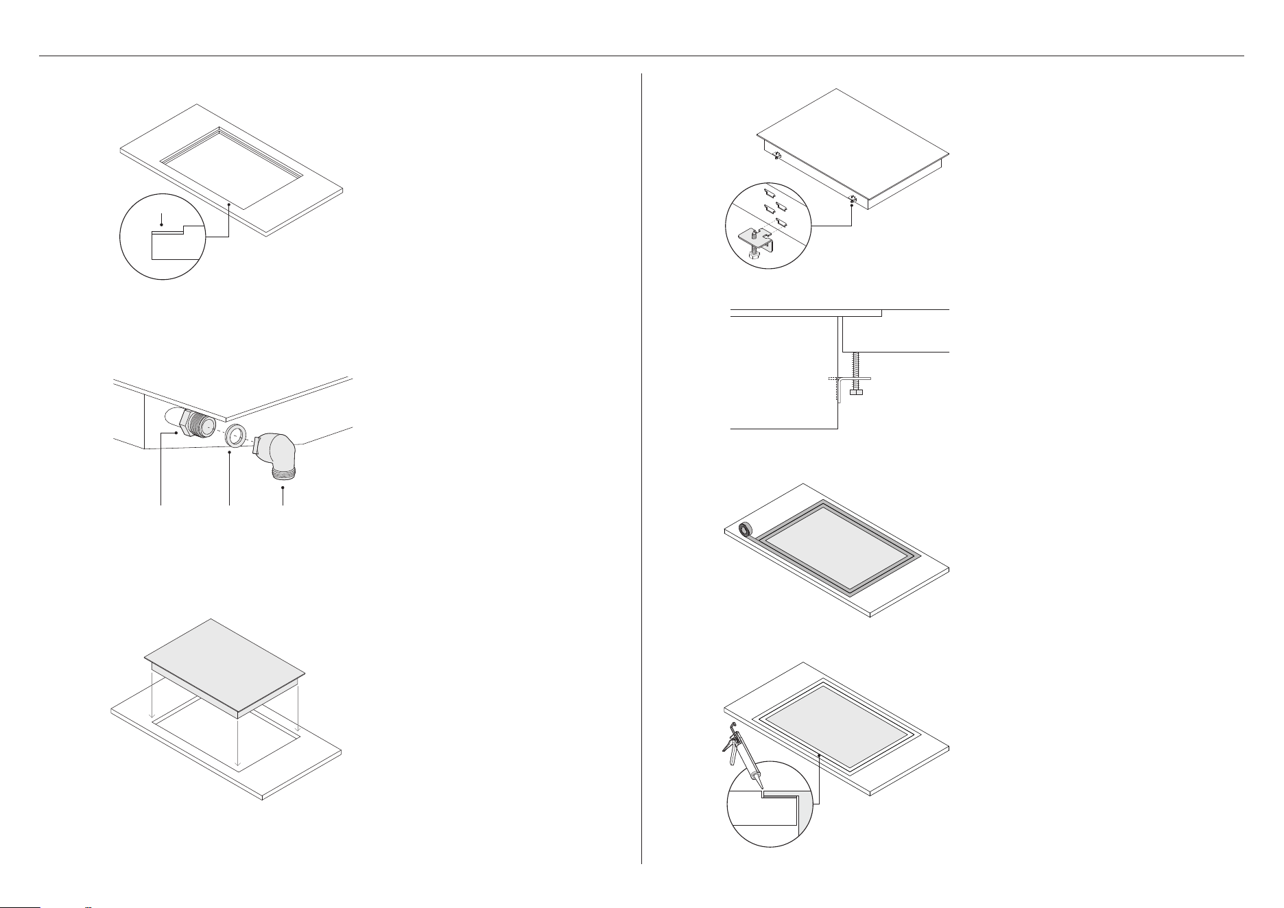
Remove the transit screws from
both sides of the cooktop.
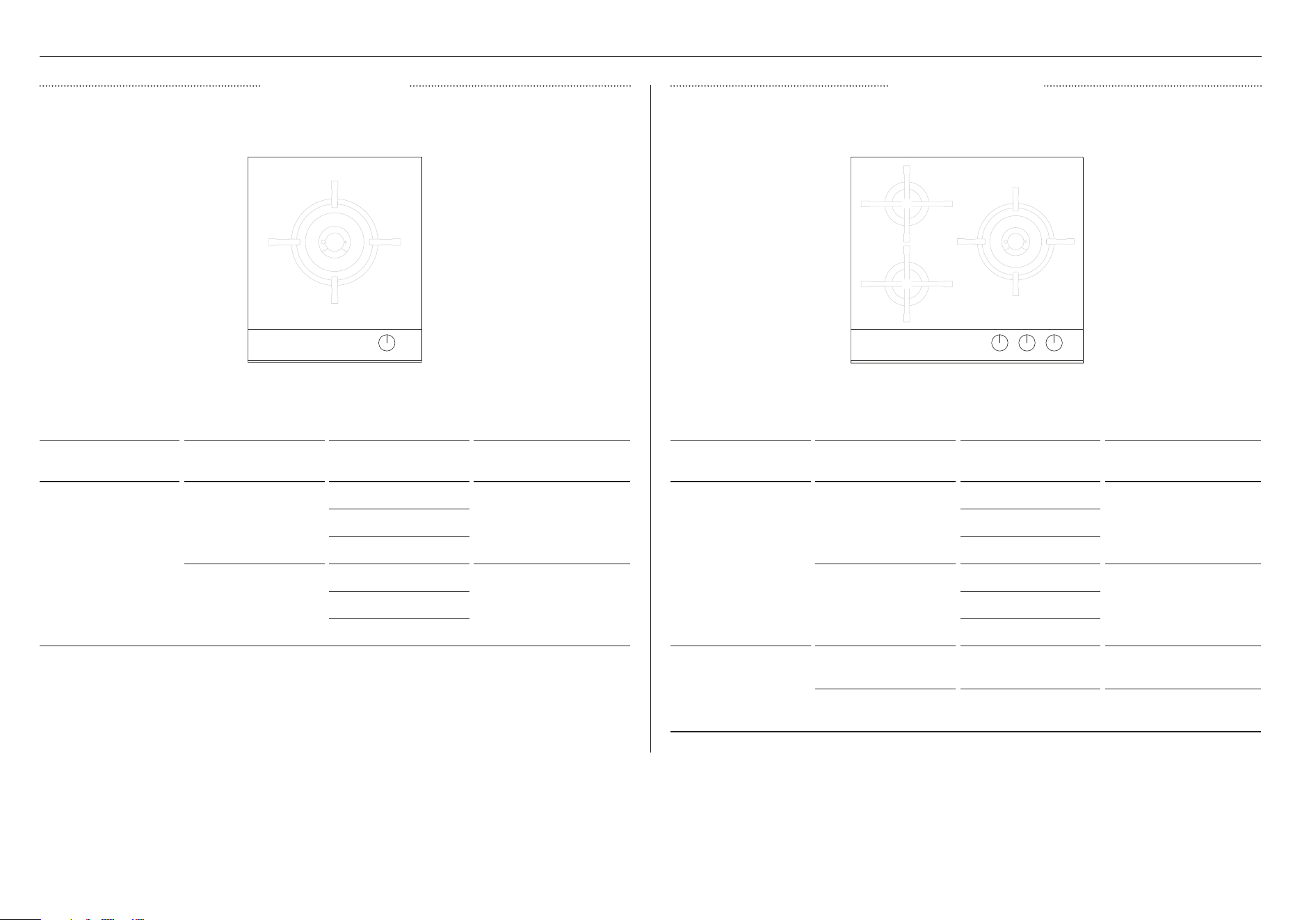
PROUD INSTALLATION
*The number of brackets varies based on your cooktop model
Gently lower the cooktop into the
cutout ensuring you have access
below the countertop to fit and
secure the brackets.
Locate the side brackets* to the
appropriate slots on the cooktop
chassis. The correct slot height is
determined by the thickness of
your countertop.
3 6
Tighten all screws to secure the
cooktop to the countertop.
Ensure cooktop is level.
Apply adhesive foam seal around
the glass overhang, 5mm in from
the edge of the glass.
Ensure the adhesive side is facing
down to form a continuous seal
around the cooktop.
Trim any excess seal using a
sharp knife taking care not to
damage the cooktop or surface.
*(1/2" BSP external thread)
Fit the elbow and washer to the
floating nut. Turn the cooktop
over carefully and place onto a
protected surface.
floating nut elbow*washer
31
2
7
5
1
6
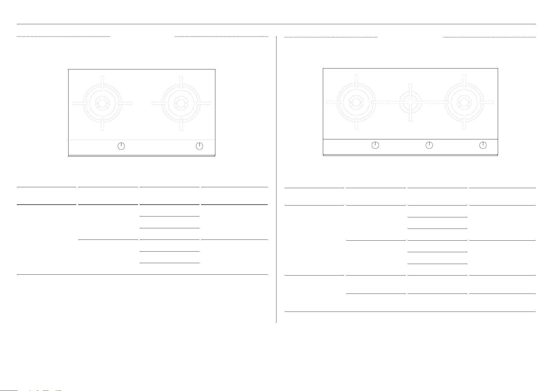
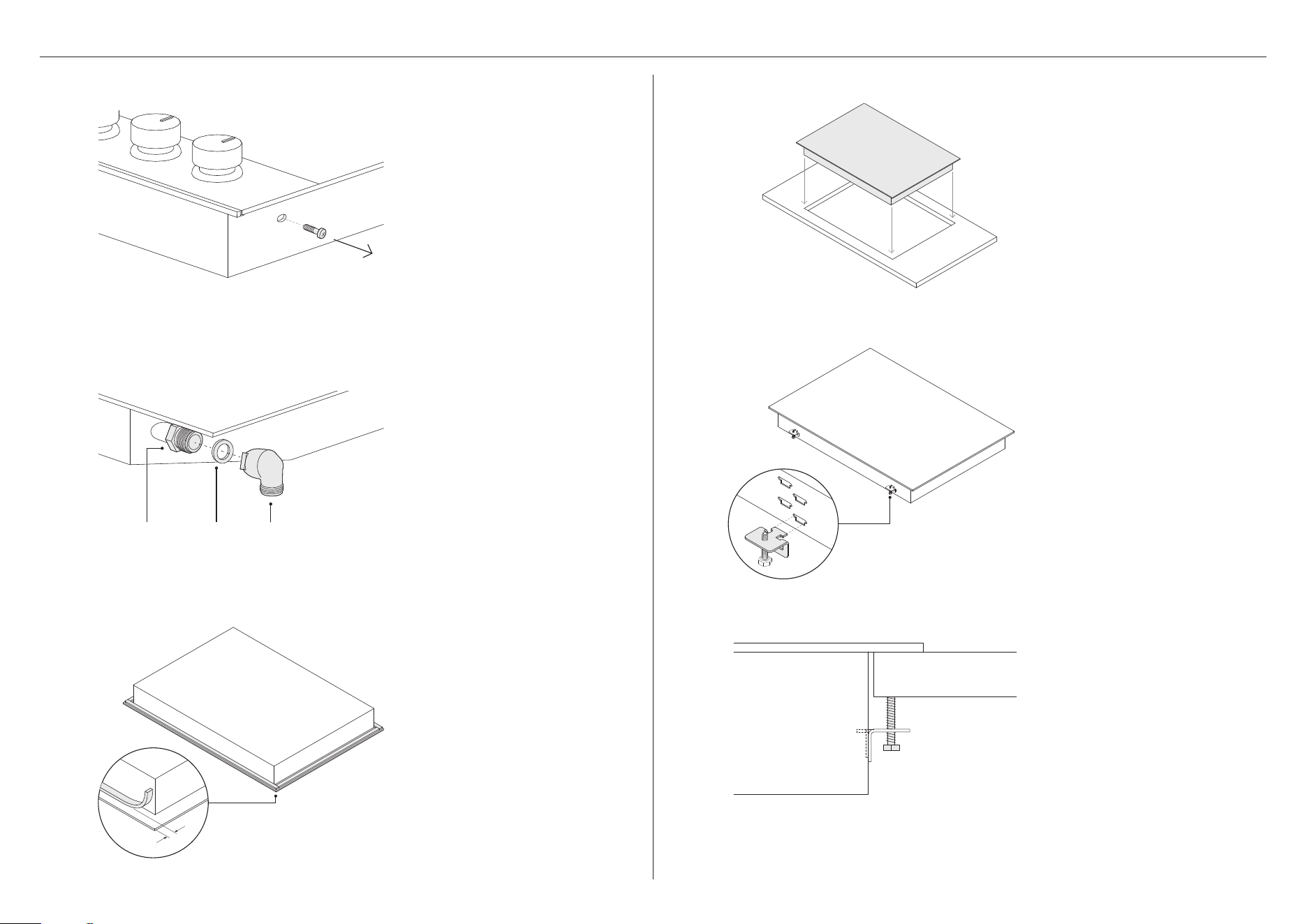
Prepare the countertop for flush
installation. Use a router to cutout
the edges of the countertop to
specified depth (5mm).
Attach an adhesive tape along
the edges of the routered recess.
Mask off the area to be siliconed
ensuring both the cooktop and
countertop are protected.
Apply silicone in the gap between
countertop and cooktop.
Wipe off any excess silicone.
FLUSH INSTALLATION
*The number of brackets varies based on your cooktop model
Tighten all screws to secure the
cooktop to the countertop.
Ensure cooktop is level.
adhesive
3
Gently lower the cooktop into the
cutout ensuring you have access
below the countertop to fit and
secure the brackets.
Locate the side brackets* to the
appropriate slots on the cooktop
chassis. The correct slot height is
determined by the thickness of
your countertop.
4
Fit the elbow and washer to the
floating nut. Turn the cooktop
over carefully and place onto a
protected surface.
floating nut elbow*washer
32
GAS CONNECTION
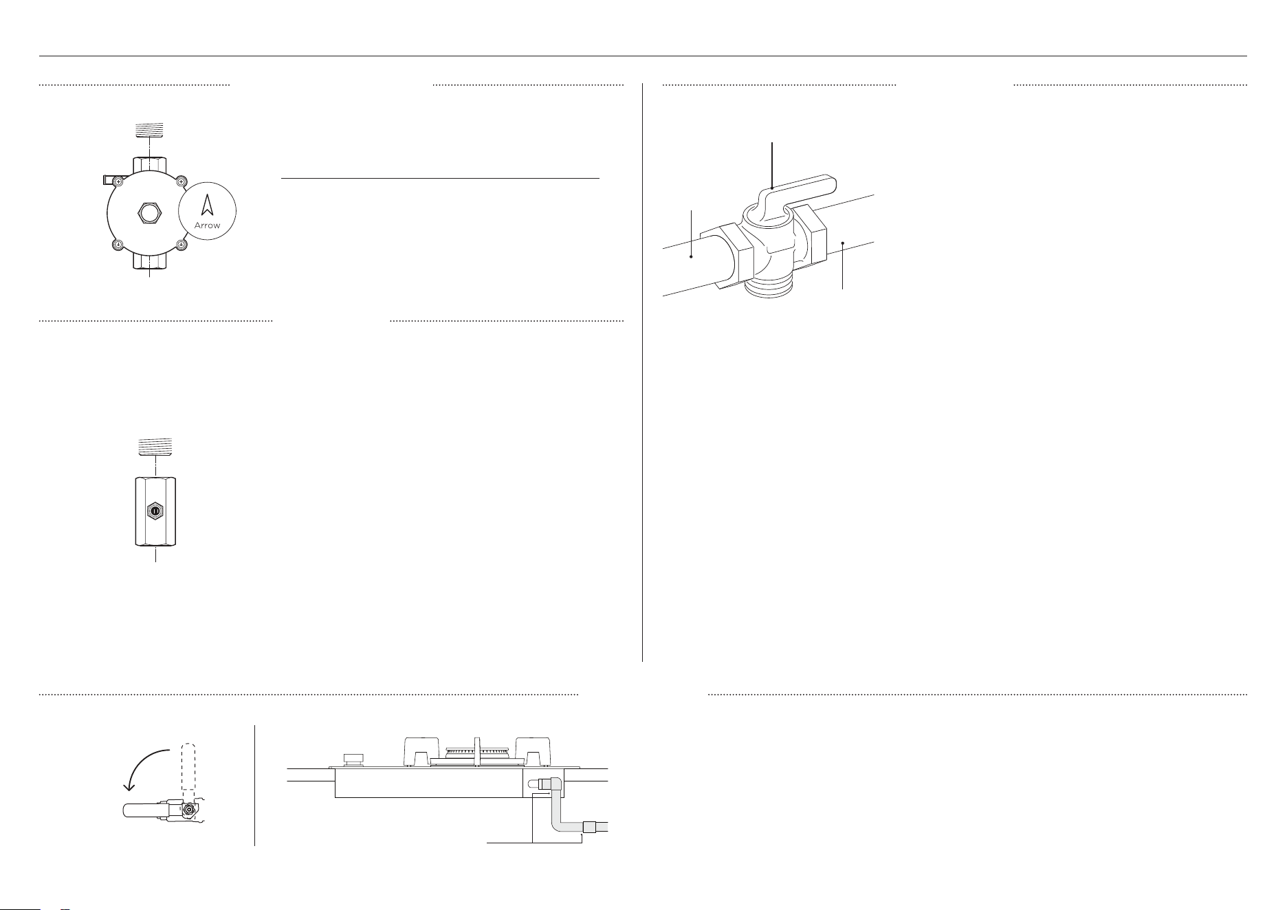
NG Models
LPG Models
z
Ensure the supplied regulator is fitted.
z
Adjust to obtain a test point pressure of 1kPa
with all burners operating at the highest setting.
NZ AU only
z
Ensure the supplied test point adapter is fitted.
z
Adjust to obtain a test point pressure of 2.75kPa with
all burners operating at the highest setting.
UK IE only
z
When operating on Butane gas a supply pressure of
28 – 30 mbar is required.
z
When operating on Propane gas a supply pressure
of 37 mbar is required.
z
Adjust the pressure with all burners operating at the
highest setting.
z
The installation must conform to the relevant
UK/EU standards.
SG only
z
Make sure the supply pressure is regulated to 2.90
kPa, with all the burners operating at highest setting.
z
Where a flexible hose is used, the hose must comply
with Standard SS 233:2013.
z
Ensure the connection point will be accessible with
the installed cooktop.
z
Use an isolating valve close to the cooktop.
If connecting the gas with a flexible hose:
z
Ensure the hose is long enough to allow for removal
of cooktop for servicing.
z
Ensure the connected is located as shown in
‘Clearace dimensions’.
z
Ensure the hose is not kinked, and not subjected to
abrasion or permanently deformed.
z
Ensure the hose is not near or in contact with any
hot surfaces (eg base of metal hotplate, flue, or
chassis of underbench oven, etc).
NZ AU only
z
The hose assembly must be AS/NZ 1869 Class
B or D certified, with an Rp 1/2" (ISO7-1) female
thread connection.
z
The hose assembly must be longer than 1.2m
in length with minimum internal diameter of 10mm
and comply with relevant AS 5601/NZS 5261
requirements.
UK IE only
z
The ambient temperature of the hose must not
exceed 70°C. These hoses must be manufactured
in accordance with BSE669 part 1 or EN 14800 and
be of the correct construction for the type of gas
being used.
z
Never use a hose designed for natural gas for
supplying LPG gas. (LPG hoses either have a red
band or stripe on the rubber outer coating of
the hose.)
z
Ensure all dials are set to OFF before connecting cooktop to gas supply.
z
After final gas connection is made, turn gas supply on and test all connections in gas
supply piping for gas leaks with a soapy water solution.
z
In order to avoid property damage or serious personal injury, never use a match or open
flame. If a leak is present, tighten joint or unscrew, apply more joint compound, tighten
again and retest connection for leak.
ON
GAS
Leak test points
Manual shut-off valve
TG - SG only
z
Elitre Type B regulator
z
Adjust to obtain a supply pressure of 1.5 kPa
(Hong Kong) or 0.8 kPa (Singapore) with all the
burners operating at the highest setting.
NATURAL GAS MODELS
LEAK TESTING
LPG MODELS
ALL MODELS
manual shut-off valve
‘open’ position
to cooktop
gas supply line
33
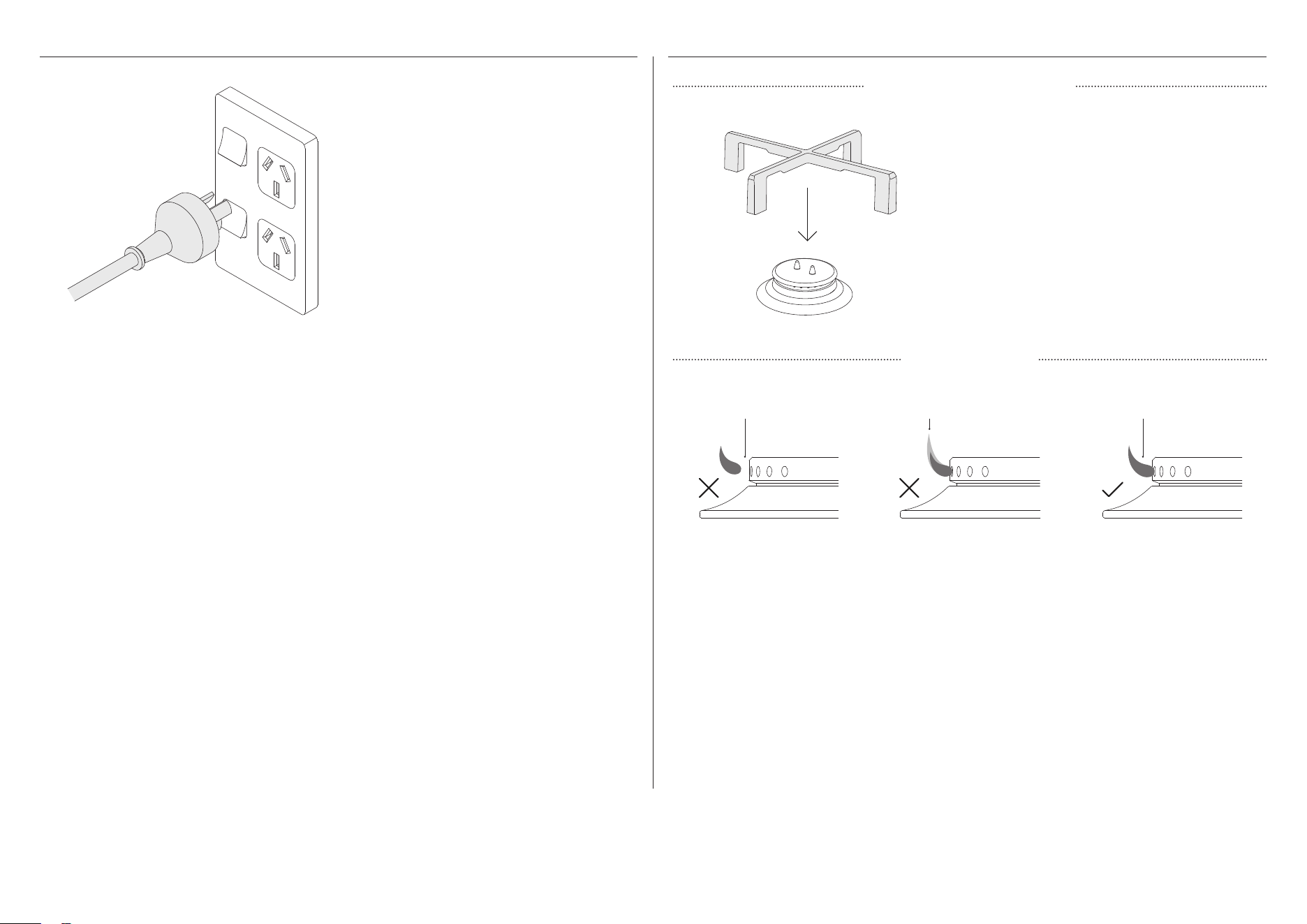
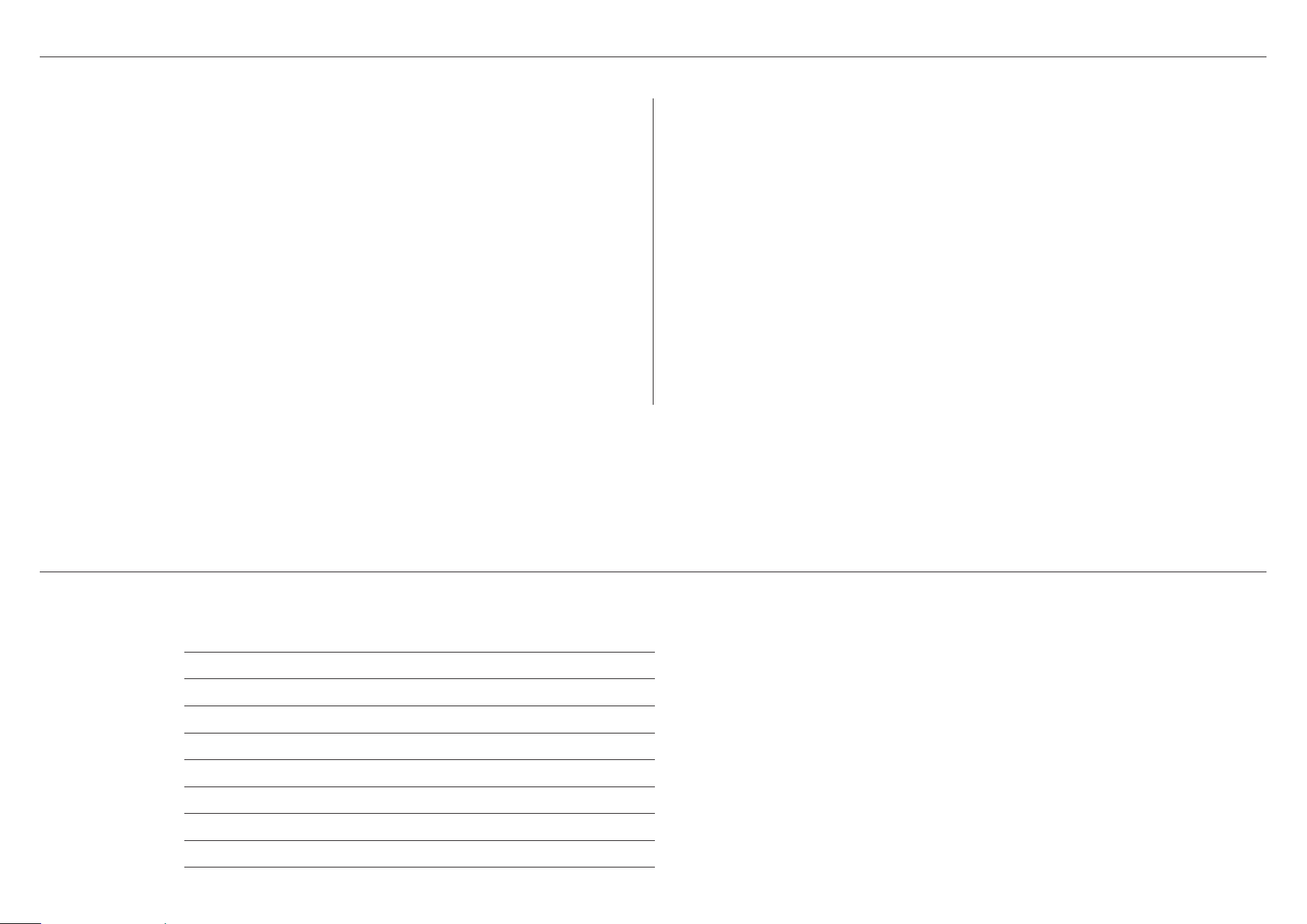
ELECTRICAL CONNECTION COOKTOP BURNERS
Connect the cooktop to the power
supply and attach the duplicate data
label to an accessible location.
z
To check that the ignition system operates correctly, light each burner by itself, then all
burners in combination.
z
Check for a well-defined blue flame without any yellow tipping.
z
If any abnormality is evident, check that the components of the burner assembly are
located properly.
z
No air shutter adjustment is possible on the cooktop. Correct operation is achieved with
factory installed settings for the correct gas type.
z
When installing the burner port ring, align the two locating pins in the bottom side of the
port ring with the locating notch and centre holes on the top side of the simmer ring, and
make sure these are properly engaged.
z
Incorrect installation may produce a potentially dangerous flame and result in poor
burner performance.
z
If proper operation cannot be obtained, contact Customer Care or your nearest
Fisher&Paykel Authorized Service Centre.
z
The cooktop must not be used by the until proper operation has been achieved.
lifting off stable blue flame
yellow tip
Securely locate all pan supports ensuring
they are the installed in the correct
orientation and do not rock.
ATTACH PAN SUPPORTS
TEST BURNERS
34
INSTALLER CHECKLIST
TO BE COMPLETED BY THE INSTALLER
GENERAL
Specified clearance maintained.
Unit is level – front to back and side to side.
All packaging materials have been removed.
Dials turn correctly and freely.
Burners light satisfactorily, both individually and with other burners operating.
There is a constant flow of cool air from the cabinetry to the base of the cooktop.
Cooktop is securely clamped.
Basic operation has been demonstrated to the customer.
GAS
Manual gas shut-off valve installed in an accessible location.
Unit tested and free of gas leaks.
ELECTRICAL
Receptacle with correctly rated over-current protection is provided for service
cordconnection.
Adequate ground connection.
Power supply cable is not touching the cooktop and accessible.
Complete and keep for safe reference:
Model
Serial No.
Purchase Date
Purchaser
Dealer Address
Installer’s Name
Installer’s Signature
Installation Company
Installation Date
35

592233H 05.25
FISHERPAYKEL.COM
© Fisher & Paykel Appliances 2025. All rights reserved.
The models shown in this guide may not be available in all markets
and are subject to change at any time.
The product specifications in this guide apply to the specific products and
models described at the date of issue. Under our policy of continuous product
improvement, these specifications may change at any time.
For current details about model and specification availability in your country,
please go to our website or contact your local Fisher&Paykel dealer.