Part Number STH106 8/20
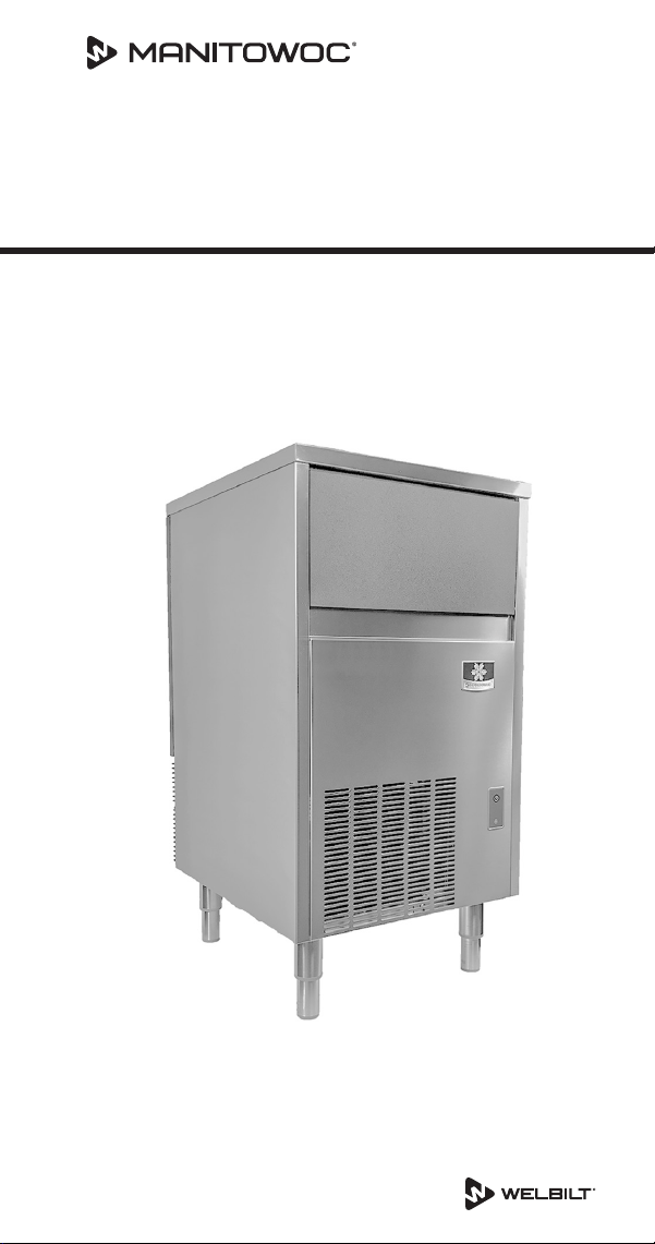
USP0100 Ice Machine
Technician’s Handbook
This manual is updated as new information and models are
released. Visit our website for the latest manual.
www.manitowocice.com


Safety Notices
Read these precautions to prevent personal injury:
• Read this manual thoroughly before operating,
installing or performing maintenance on the
equipment. Failure to follow instructions in this
manual can cause property damage, injury or death.
• Routine adjustments and maintenance procedures
outlined in this manual are not covered by the
warranty.
• Proper installation, care and maintenance are essential
for maximum performance and trouble-free operation
of your equipment.
• Visit our website www.manitowocice.com for manual
updates, translations, or contact information for
service agents in your area.
• This equipment contains high voltage electricity and
refrigerant charge. Installation and repairs are to be
performed by properly trained technicians aware of
the dangers of dealing with high voltage electricity
and refrigerant under pressure. The technician
must also be certified in proper refrigerant handling
and servicing procedures. All lockout and tag out
procedures must be followed when working on this
equipment.
• This equipment is intended for indoor use only. Do not
install or operate this equipment in outdoor areas.
• As you work on this equipment, be sure to pay close
attention to the safety notices in this handbook.
Disregarding the notices may lead to serious injury
and/or damage to the equipment.

Definitions
DANGER
Indicates a hazardous situation that, if not avoided,
may result in death or serious injury. This applies to
the most extreme situations.
n
Warning
Indicates a hazardous situation that, if not avoided,
may result in death or serious injury.
,
Caution
Indicates a hazardous situation which, if not avoided,
may result in minor or moderate injury.
Important
Indicates information considered important, but not
hazard related (e.g. messages relating to property
damage).
NOTE: Indicates useful and extra information about the
procedure you are performing.

n
Warning
Follow these electrical requirements during installation
of this equipment.
• All field wiring must conform to all applicable
codes of the authority having jurisdiction. It is
the responsibility of the end user to provide the
disconnect means to satisfy local codes. Refer to
rating plate for proper voltage.
• This appliance must be grounded.
• This equipment must be positioned so that the plug
is accessible unless other means for disconnection
from the power supply (e.g., circuit breaker or
disconnect switch) is provided.
• Check all wiring connections, including factory
terminals, before operation. Connections can
become loose during shipment and installation.
• For a cord-connected appliance, the following must
be included:
• Do not unplug by pulling on cord. To unplug,
grasp the plug, not the cord.
• Unplug from outlet when not in use and before
servicing or cleaning.
• Do not operate any appliance with a damaged
cord or plug, or after the appliance malfunctions
or is dropped or damaged in any manner.
Contact the nearest authorized service
facility for examination, repair, or electrical or
mechanical adjustment.

n
Warning
Follow these precautions to prevent personal injury
during installation of this equipment:
• Installation must comply with all applicable
equipment fire and health codes with the authority
having jurisdiction.
• To avoid instability the installation area must be
capable of supporting the combined weight of the
equipment and product. Additionally the equipment
must be level side to side and front to back.
• Remove front panel before lifting and installing and
use appropriate safety equipment during installation
and servicing. Two or more people are required to
lift or move this appliance to prevent tipping and/
or injury.
• Do not damage the refrigeration circuit when
installing, maintaining or servicing the unit.
• Connect to a potable water supply only.
• This equipment contains refrigerant charge.

n
Warning
Follow these precautions to prevent personal injury
while operating or maintaining this equipment.
• Legs or casters must be installed and the legs/casters
must be screwed in completely. When casters
are installed the mass of this unit will allow it to
move uncontrolled on an inclined surface. These
units must be tethered/secured to comply with all
applicable codes. Swivel casters must be mounted
on the front and rigid casters must be mounted on
the rear. Lock the front casters after installation is
complete.
• Only trained and qualified personnel aware of the
dangers are allowed to work on the equipment.
• Read this manual thoroughly before operating,
installing or performing maintenance on the
equipment. Failure to follow instructions in this
manual can cause property damage, injury or death.
• Crush/Pinch Hazard. Keep hands clear of moving
components. Components can move without
warning unless power is disconnected and all
potential energy is removed.
• Moisture collecting on the floor will create a
slippery surface. Clean up any water on the floor
immediately to prevent a slip hazard.

n
Warning
Follow these precautions to prevent personal injury
while operating or maintaining this equipment.
• Objects placed or dropped in the bin can affect
human health and safety. Locate and remove any
objects immediately.
• Never use sharp objects or tools to remove ice or
frost.
• Do not use mechanical devices or other means to
accelerate the defrosting process.
• When using cleaning fluids or chemicals, rubber
gloves and eye protection (and/or face shield) must
be worn.
DANGER
Do not operate equipment that has been misused,
abused, neglected, damaged, or altered/modified
from that of original manufactured specifications. This
appliance is not intended for use by persons (including
children) with reduced physical, sensory or mental
capabilities, or lack of experience and knowledge,
unless they have been given supervision concerning
use of the appliance by a person responsible for their
safety. Do not allow children to play with, clean or
maintain this appliance without proper supervision.

DANGER
Follow these precautions to prevent personal injury
during use and maintenance of this equipment:
• It is the responsibility of the equipment owner to
perform a Personal Protective Equipment Hazard
Assessment to ensure adequate protection during
maintenance procedures.
• Do Not Store Or Use Gasoline Or Other Flammable
Vapors Or Liquids In The Vicinity Of This Or Any
Other Appliance.
• Never use flammable oil soaked cloths or
combustible cleaning solutions for cleaning.
• All covers and access panels must be in place and
properly secured when operating this equipment.
• Risk of fire/shock. All minimum clearances must be
maintained. Do not obstruct vents or openings.
• Failure to disconnect power at the main power
supply disconnect could result in serious injury or
death. The power switch DOES NOT disconnect all
incoming power.
• All utility connections and fixtures must be
maintained in accordance with the authority having
jurisdiction.

n
Warning
Follow these precautions to prevent personal injury
during use and maintenance of this equipment:
• It is the responsibility of the site supervisor to
ensure that operators fully understand the dangers
inherent in operating this equipment.
• Turn off and lockout all utilities (gas, electric, water)
according to approved practices during maintenance
or servicing.
• Do not operate any equipment with damaged
cords or plugs. All repairs must be performed by a
qualified service company.
• Moisture collecting on the floor will create a
slippery surface. Clean up any water on the floor
immediately to prevent a slip hazard.
• Do not use high-pressure water guns to spray or
rinse the interior or exterior of the unit. Do not use
power cleaning equipment, steel wool, wire brushes,
scrapers, etc. to clean the exterior of the equipment.
• To prevent tipping, two or more people are needed
to move this appliance.
We reserve the right to make product improvements at
any time. Specifications and design are subject to change
without notice.

DANGER
Follow these flammable refrigeration system
requirements during installation, use or repair of this
equipment.
• To minimize the risk of ignition due to improper
installation, replacement parts or service
procedures, only refrigeration technicians with
flammable refrigerant training who are aware of the
dangers of dealing with high voltage electricity and
refrigerant under pressure are allowed to work on
this equipment.
• Models may contain up to 150 grams of R290
(propane) refrigerant. R290 (propane) is flammable
in concentrations of air between approximately
2.1% and 9.5% by volume (LEL lower explosion limit
and UEL upper explosion limit). An ignition source
at a temperature higher than 470°C is needed for a
combustion to occur.
• Refer to nameplate to identify the type of refrigerant
in your equipment.
• All replacement parts must be like components
obtained from the equipment manufacturers
authorized replacement part network.
• All replacement parts must be like components
obtained from the equipment manufacturers
authorized replacement part network.
• This equipment must be installed in accordance with
the ASHRAE 15 Safety Standard for Refrigeration
Systems.
• This equipment can not be installed in corridors or
hallways of public buildings.

DANGER
Follow these flammable refrigeration system
requirements during installation, use or repair of this
equipment.
• Installation must comply with all applicable
equipment fire and health codes with the authority
having jurisdiction.
• All lockout and tag out procedures must be followed
when working on this equipment.
• This equipment contains high voltage electricity
and refrigerant charge. Shorting electrical wires to
refrigeration tubing may result in an explosion. All
electrical power must be disconnected from the
system before servicing the system. Refrigerant
leaks, can result in serious injury or death from
explosion, fire, or contact with refrigerant or
lubricant mists.
• Do not damage the refrigeration circuit when
installing, maintaining or servicing the unit. Never
use sharp objects or tools to remove ice or frost.
Do not use mechanical devices or other means to
accelerate the defrosting process.

Table of Contents
Part Number STH106 8/20 13
Safety Notices....................................3
Definitions .......................................4
General Information
Model Numbers................................ 17
How to Read a Model Number.................. 17
Model/Serial Number Location ................. 18
Warranty ...................................... 18
Warranty Registration....................18
Installation
Location of Ice Machine ........................ 19
Ice Machine Clearance Requirements ........... 20
Ice Machine Heat of Rejection .................. 20
Leveling the Ice Machine ....................... 20
Electrical Requirements ........................ 21
Electrical Specifications......................... 21
Water Service/Drains........................... 22
Water Supply ...........................22
Maintenance
Detailed Cleaning and Sanitizing ................ 25
General................................25
Exterior Cleaning ........................25
Detailed Descaling/Sanitizing Procedure ....26
Remedial Cleaning Procedure................... 33
Cleaning the Condenser ........................ 37
General................................37
Removal from Service/Winterization........38

14 Part Number STH106 8/20
Operation
Ice Making Sequence of Operation.............. 39
Freeze Cycle ............................40
Harvest Cycle ...........................40
Automatic Shut-off ......................41
Electronic Timer, Power, Wash, Defrost Switch .. 42
Ice Cube Thickness Check....................... 43
Ice Cube Weight Adjustment.................... 43
Bin Thermostat Adjustment .................... 44
Removal from Service/Long Term Storage ....... 44
Troubleshooting
Electronic Timer Diagnostics.................... 45
Ice machine is not running ................45
Troubleshooting................................ 46
Diagnosing an Ice Machine that Will Not Run 46
Diagnosing an Ice Machine that Does not cycle
into harvest ............................47
Diagnosing an Ice Machine that Cycles Into
Harvest Prematurely .....................48
Eliminate all non refrigeration problems before
diagnosing the refrigeration system. .......49
Installation/Visual Inspection Checklist......49
Water System Checklist...................50
Ice Formation Pattern ....................51
Ice Production Check ....................53
Refrigeration System Diagnostics ............... 55
Refrigeration Diagnostic Procedure.........55
Freeze Cycle Analysis Chart ...............56
Discharge Line Temperature...............57
Suction Line Temperature.................57
Leaking Harvest Valve ....................57
Overcharged System Symptoms............57
Restricted Capillary Tube/Low Refrigerant
Charge Symptoms .......................58
Higher than normal freeze cycle temperatures .
......................................58

Part Number STH106 8/20 15
Component Check Procedures
Electronic Timer................................ 59
Power, Wash, Defrost Switch ..............59
Service Faults .................................. 61
Bin Thermostat .........................62
Evaporator Thermostat...................63
Fan Cycle Control........................64
Compressor Electrical Diagnostics ..........65
Filter-Driers .................................... 67
Flammable Refrigerant Procedures
Servicing Requirements ........................ 68
Refrigerant Purging Requirements .........69
Refrigerant Purging Procedure.............70
Brazing Procedure .......................70
Pressure Testing.........................71
Evacuation .............................71
Refrigerant Charging ........................... 72
System Contamination Cleanup................. 74
Determining Severity of Contamination .....74
Mild System Contamination Cleanup Procedure
......................................76
Severe System Contamination Cleanup
Procedure..............................77
Total System Refrigerant Charge ................ 78
Charts
Cycle Times, 24 Hr. Ice Production and Refrigerant
Temperature Charts ............................ 79
USP0100A Air-cooled ....................80
Diagrams
Wiring Diagrams ............................... 83
USP0100A 1Ph Air-cooled.................84

Part Number STH106 8/20 17
Model Numbers
This manual covers the following models:
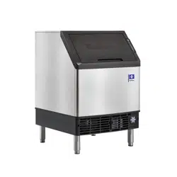
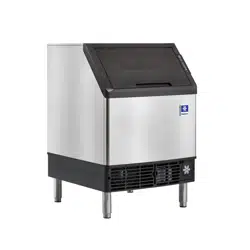
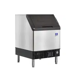
Self-contained Air-cooled
USP0100A
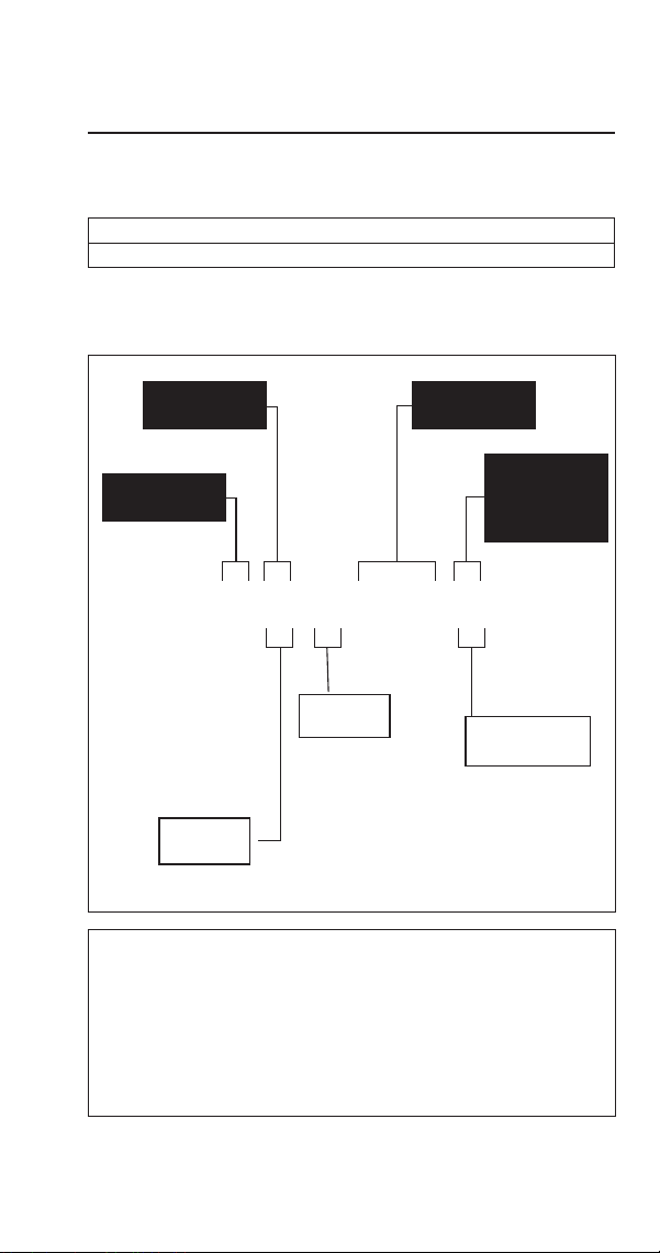
How to Read a Model Number
U S P - 0100 A
Cube Size
Series
Capacity
Condenser
Type
A - Air-cooled
S - Square
n
Warning
An ice machine contains high voltage electricity and
refrigerant charge. Repairs are to be performed by
properly trained refrigeration technicians aware of the
dangers of dealing with high voltage electricity and
refrigerant under pressure.
General Information
Refrigerant
P - R290

18 Part Number STH106 8/20
Model/Serial Number Location
These numbers are required when requesting information
from your local Manitowoc Distributor, Service
Representative, or Manitowoc Ice.
The model/serial number data plate is located in the
evaporator compartment and on the back of the ice
machine.
Warranty
For warranty information visit:
www.manitowocice.com/Service/Warranty
• Warranty Coverage Information
• Warranty Registration
• Warranty Verification
Warranty coverage begins the day the ice machine is
installed.
WARRANTY REGISTRATION
Completing the warranty registration process is a quick and
easy way to protect your investment.
Scan the QR code with your smart device or enter the link
in a web browser to complete your warranty registration.
WWW.MANITOWOCICE.COM/SERVICE/WARRANTY#WARRANTY-
REGISTRATION
Registering your product insures warranty coverage and
streamlines the process if any warranty work is required.

Part Number STH106 8/20 19
Location of Ice Machine
The location selected for the ice machine must meet the
following criteria. If any of these criteria are not met,
select another location.
• The location must be indoors.
• The location must be free of airborne and other
contaminants.
• Air temperature: Must be at least 50°F (10°C) but must
not exceed 113°F (43.4°C).
• The location must not be near heat-generating
equipment or in direct sunlight.
• The location must be capable of supporting the weight
of the ice machine and a full bin of ice.
• The location must allow enough clearance for water,
drain, and electrical connections in the rear of the ice
machine.
• The location must not obstruct airflow through or
around the ice machine (condenser airflow is in and
out the front). Refer to the chart below for clearance
requirements.
• The ice machine must be protected if it will be
subjected to temperatures below 32°F (0°C). Failure
caused by exposure to freezing temperatures is not
covered by the warranty.
Installation

20 Part Number STH106 8/20
Ice Machine Clearance Requirements
Self-contained Air-cooled
Top/Sides 5" (127 mm)*
Back 5" (127 mm)*
*The ice machine may be built into a cabinet.
Ice Machine Heat of Rejection
Series
Ice Machine
Heat of Rejection*
Air Conditioning** Peak
USP0100A 2350 Btu/h 3637 Btu/h
* B.T.U./Hour
** Because the heat of rejection varies during the ice
making cycle, the figure shown is an average.
Ice machines, like other refrigeration equipment, reject
heat through the condenser. It is helpful to know the
amount of heat rejected by the ice machine when sizing air
conditioning equipment where self-contained air-cooled
ice machines are installed.
Leveling the Ice Machine
1. Screw the legs onto the bottom of the ice machine.
2. Screw the foot of each leg in as far as possible.
,
Caution
The legs must be screwed in tightly to prevent them
from bending.
3. Move the ice machine into its final position.
4. Level the ice machine to ensure that the drain system
functions correctly. Use a level on top of the ice
machine. Turn each foot as necessary to level the ice
machine from front to back and side to side.
Part Number STH106 8/20 21
Electrical Requirements
Voltage
The maximum allowable voltage variation is ±10% of the
rated voltage on the ice machine model/serial number
plate at start-up (when the electrical load is highest).
Fuse/Circuit Breaker
A separate fuse/circuit breaker must be provided for each
ice machine.
Total Circuit Ampacity
The total circuit ampacity is used to help select the wire
size of the electrical supply.
The wire size (or gauge) is also dependent upon location,
materials used, length of run, etc., so it must be
determined by a qualified electrician.
Electrical Specifications
Air-cooled Ice Machine
Ice Machine
Voltage Phase
Cycle
Max. Fuse/
Circuit Breaker
Total Amps
USP0100A 115/1/60 15 amp 10 amp
NOTE: Model/serial plate information overrides all data listed in
this chart.
n
Warning
All wiring must conform to local, and national codes.
n
Warning
The ice machine must be grounded in accordance with
national and local electrical code.

22 Part Number STH106 8/20
Water Service/Drains
WATER SUPPLY
Local water conditions may require treatment of the water
to inhibit scale formation, filter sediment, and remove
chlorine odor and taste.
Important
If you are installing a Manitowoc water filter system,
refer to the Installation Instructions supplied with the
filter system for ice making water inlet connections.
n
Warning
For ice making, connect to a potable water supply only.
Water Inlet Lines
Follow these guidelines to install water inlet lines:
• Do not connect the ice machine to a hot water supply.
Be sure all hot water restrictors installed for other
equipment are working. (Check valves on sink faucets,
dishwashers, etc.).
• If water pressure exceeds the maximum recommended
pressure, 80 psig (5.5 bar) obtain a water pressure
regulator from your Manitowoc distributor.
• Install a water shut-off valve for ice making potable
water.
• Insulate water inlet lines to prevent condensation.

Part Number STH106 8/20 23
Drain Connections
Follow these guidelines when installing drain lines to
prevent drain water from flowing back into the ice
machine and storage bin:
• Drain lines must have a 1.5-inch drop per 5 feet of run
(2.5 cm per meter), and must not create traps.
• The floor drain must be large enough to accommodate
drainage from all drains.
• Install a tee to vent the ice machine drain to the
atmosphere.
• Insulate drain lines to prevent condensation.
,
Caution
Plumbing must conform to state and local codes.

24 Part Number STH106 8/20
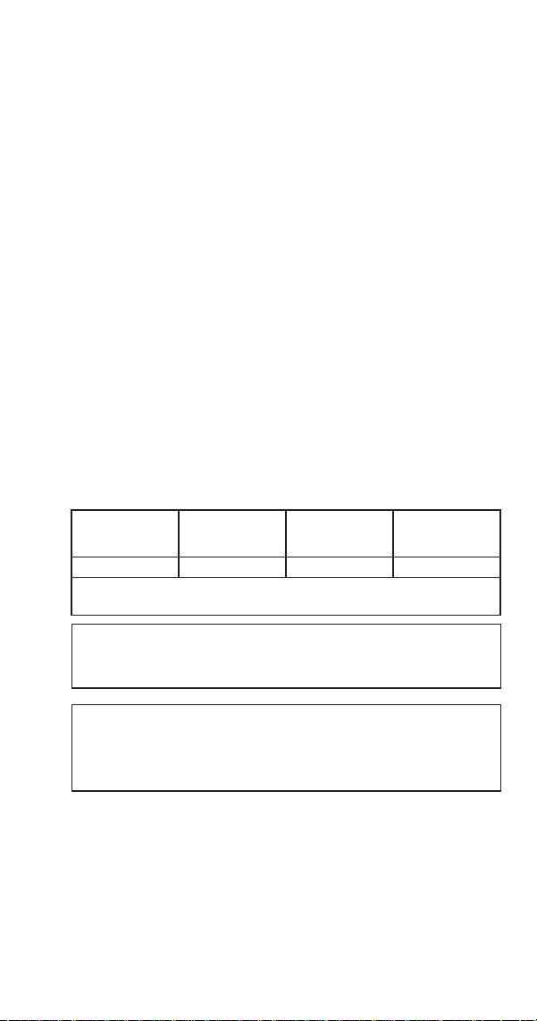
Water Supply and Drain Line Sizing/Connections
Location
Water
Temperature
Water
Pressure
Ice Machine Fitting Tubing Size Up to Ice Machine Fitting
Ice Making
Water Inlet
40°F (4°C) min.
90°F (32°C) max.
20 psi (138 kPa) min.
80 psi (550 kPa) max.
3/8” Female Pipe Thread 3/8" (9.5 mm) min. inside diameter
Bin Drain --- --- 1/2” Female Pipe thread 1/2” (12.7 mm) min. inside diameter

Part Number STH106 8/20 25
Detailed Cleaning and Sanitizing
GENERAL
You are responsible for maintaining the ice machine
in accordance with the instructions in this manual.
Maintenance procedures are not covered by the warranty.
Descale and sanitize the ice machine every 12 months
for efficient operation. If the ice machine requires more
frequent cleaning and sanitizing, consult a qualified
service company to test the water quality and recommend
appropriate water treatment. The ice machine must be
taken apart for cleaning and sanitizing.
,
Caution
Damage to the ice machine evaporator caused
by incorrect chemical usage is not covered by the
warranty.
n
Warning
Wear rubber gloves and safety goggles (and/or face
shield) when handling vinegar and bleach.
EXTERIOR CLEANING
Clean the area around the ice machine as often as
necessary to maintain cleanliness and efficient operation.
Wipe surfaces with a damp cloth rinsed in water to remove
dust and dirt from the outside of the ice machine. If a
greasy residue persists, use a damp cloth rinsed in a mild
dish soap and water solution. Wipe dry with a clean, soft
cloth.
Products containing abrasives may damage/scratch the
panels. Never use steel wool or abrasive pads for cleaning.
Maintenance

26 Part Number STH106 8/20
DETAILED DESCALING/SANITIZING PROCEDURE
This procedure must be performed every twelve months.
• The ice machine and bin must be disassembled
descaled and sanitized.
Step 1 Open the bin door to access the evaporator
compartment. Ice must not be on the evaporator during
cleaning and sanitizing. Follow one of the methods below:
• Press the power switch at the end of a harvest cycle
after ice falls from the evaporator(s).
• Press the defrost switch to initiate a harvest.
(See Step 3 for front panel removal).
• Press the power switch and allow the ice to melt.
,
Caution
Never use anything to force ice from the evaporator.
Damage may result.
Step 2 Remove all ice from the bin and remove top
cover of ice machine.
Part Number STH106 8/20 27
n
Warning
Risk of electrical shock or burns. Do not touch electrical
wiring or insert hands into the area the front panel
covered while performing the following step.
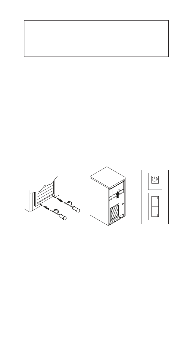
Step 3 Remove front panel to access Wash/Defrost
button:
• Using a small Philips screwdriver, loosen the 2 lower
screws behind the grill of the front panel, then lift up
on the front panel and remove.
• Press the Power button and then press the Wash
button.
• While the ice machine is going through the Harvest
cycle, replace the front panel without tightening the
screws.
WASH
W
DEFR
D
28 Part Number STH106 8/20
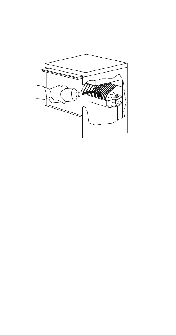
Step 4 After the harvest cycle is complete (the
compressor will stop and the pump will start spraying
water), lift some of the shutters and pour in 1 quart (4
cups) of white vinegar.
Step 5 When the 90 minute wash cycle is complete
(compressor energizes and starts a freeze cycle), press the
Power button to stop the ice machine.
Step 6 Disconnect electrical power and water.
Part Number STH106 8/20 29
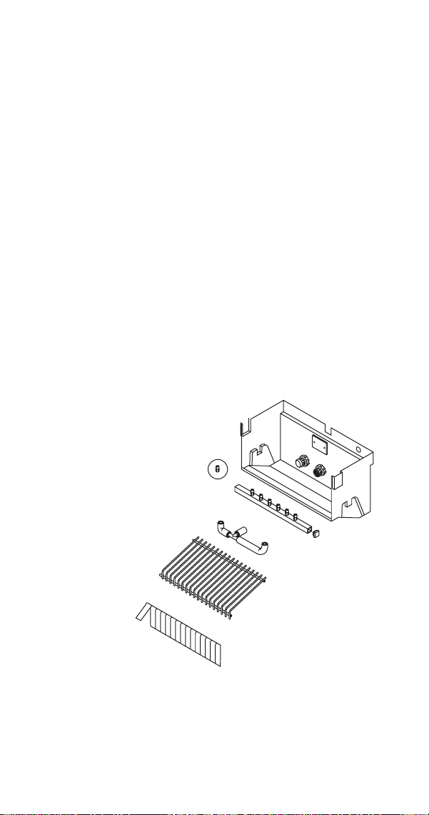
Step 7 Remove parts for cleaning.
A. Remove the shutter assembly
B. Remove ice cube slide
C. Remove overflow tube
D. Remove drain water sump
E. Remove spray bar and vinyl tubing
F. Remove pump inlet filter
G. Remove the top panel
H. Remove evaporator shield located on top of the
evaporator
NOTE: Disassemble the tubing, spray bar ends and nozzles
for easier cleaning.

30 Part Number STH106 8/20
Step 8 Transfer the removed parts to a sink and clean
with a mild dish washing soap and water, then rinse
thoroughly with clean water. Mix a 25% solution of white
vinegar and lukewarm water. Depending upon the amount
of mineral buildup, a larger quantity of solution may be
required. Use the ratio in the table below to mix enough
solution to remove all lime scale from the removed parts,
evaporator, bin and bin door.
Solution Type Water White Vinegar
Delimer 1 gal. (4 L) 1 quart (4 cups)
Step 9 Use 1/2 of the vinegar/water mixture to clean
all components. Use a soft-bristle nylon brush, sponge or
cloth (NOT a wire brush) to carefully clean the parts. Rinse
all components with clean water.
Step 10 While components are soaking, use 1/2 of the
vinegar/water solution to clean all foodzone surfaces of
the ice machine and bin. Use a nylon brush or cloth to
thoroughly clean the following ice machine areas:
• Top of the evaporator
• Water trough interior/exterior
• Evaporator and plastic parts - including top, bottom,
and sides
• Bin
Important
Take care to avoid bending evaporator coils or
dislodging/disturbing the water inlet or thermostat.
The drain holes in the evaporator base must be open
to allow water to drain freely.
,
Caution
Do not use metal objects to clear evaporator drain
holes damage will result.

Part Number STH106 8/20 31
Step 11 Rinse all areas thoroughly with clean water.
Step 12 Mix a solution of bleach and lukewarm water.
Solution Type Water Mixed With
Sanitizer 2 gal. 1 oz Bleach
Step 13 Use 1/2 of the sanitizer/water solution to
sanitize all removed components. Use a sponge or cloth to
liberally apply the solution to all surfaces of the removed
parts or soak the removed parts in the sanitizer/water
solution. Rinse all areas thoroughly with clean water.
Step 14 Sanitize all foodzone surfaces of the ice
machine and bin. Use a sponge or cloth to liberally apply
the solution to all surfaces. When sanitizing, pay particular
attention to the following areas:
• Top of the evaporator
• Water trough interior/exterior
• Evaporator and plastic parts - including top, bottom,
and sides
• Bin
Rinse all areas thoroughly with clean water.
Step 15 Replace all removed components.
NOTE: Spray bar and nozzles.
• If the nozzles were removed from the spray bar, take
care to prevent cross threading when reassembling.
• Verify the spray bar is correctly positioned and the
nozzles are aligned to the evaporator cups.

32 Part Number STH106 8/20
Step 16 Reapply power and water to the ice machine.
n
Warning
Risk of electrical shock or burns. Do not touch electrical
wiring or insert hands into the area the front panel
covers while performing the following step.
Step 17 Remove front panel to access Wash button:
• Press the Power button and then press the Wash
button.
• While the ice machine is going through the Harvest
cycle, replace the front panel and tighten the screws
using a small Philips screwdriver.
Step 18 After the harvest cycle is complete (the
compressor will stop and the pump will start spraying
water), lift some of the shutters and pour in 1/2 oz (.5 oz)
of bleach.
Step 19 When the 90 minute sanitize cycle is complete
the compressor energizes and starts a freeze cycle.
Step 20 Discard the first two batches of ice to remove
any flavor transmission from the cleaning/sanitizing
process.

Part Number STH106 8/20 33
Remedial Cleaning Procedure
This procedure must be performed every six months
between the yearly Detailed Descaling/Sanitizing
Procedure.
Step 1 Open the bin door to access the evaporator
compartment. Ice must not be on the evaporator during
cleaning and sanitizing. Follow one of the methods below:
• Press the power switch at the end of a harvest cycle
after ice falls from the evaporator(s).
• Press the power switch and allow the ice to melt.
,
Caution
Never use anything to force ice from the evaporator.
Damage may result.
Step 2 Remove all ice from the bin and remove top
cover of ice machine.
n
Warning
Risk of electrical shock or burns. Do not touch electrical
wiring or insert hands into the area the front panel
covered while performing the following step.
Step 3 Disconnect electrical power and water.

34 Part Number STH106 8/20
Step 4 Remove parts for cleaning.
A. Remove the shutter assembly
B. Remove ice cube slide
C. Remove overflow tube
D. Remove drain water sump
E. Remove spray bar and vinyl tubing
F. Remove pump inlet filter
G. Remove the top panel
H. Remove evaporator shield located on top of the
evaporator
NOTE: Disassemble the tubing, spray bar ends and nozzles
for easier cleaning.
Step 5 Transfer the removed parts to a sink and clean
with a mild dish washing soap and water:
Step 6 Rinse all areas thoroughly with clean water.
Step 7 Mix a 25% solution of white vinegar and
lukewarm water. Depending upon the amount of mineral
buildup, a larger quantity of solution may be required.
Use the ratio in the table below to mix enough solution to
remove all lime scale from the removed parts, evaporator,
bin and bin door.
Solution Type Water White Vinegar
Delimer 1 gal. (4 L) 1 quart (4 cups)

Part Number STH106 8/20 35
Step 8 Use 1/2 of the vinegar/water mixture to clean
all components. Use a soft-bristle nylon brush, sponge or
cloth (NOT a wire brush) to carefully clean the parts. Rinse
all components with clean water.
Step 9 While components are soaking, use 1/2 of the
vinegar/water solution to clean all foodzone surfaces of
the ice machine and bin. Use a nylon brush or cloth to
thoroughly clean the following ice machine areas:
• Top of the evaporator
• Water trough interior/exterior
• Evaporator and plastic parts - including top, bottom,
and sides
• Bin
Important
Take care to avoid bending evaporator coils or
dislodging/disturbing the water inlet or thermostat.
The drain holes in the evaporator base must be open
to allow water to drain freely.
,
Caution
Do not use metal objects to clear evaporator drain
holes damage will result.
Step 10 Rinse all areas thoroughly with clean water.

36 Part Number STH106 8/20
Step 11 Mix a solution of bleach and lukewarm water.
Solution Type Water Mixed With
Sanitizer 2 gal. 1 oz Bleach
Step 12 Use 1/2 of the sanitizer/water solution to
sanitize all removed components. Use a sponge or cloth to
liberally apply the solution to all surfaces of the removed
parts or soak the removed parts in the sanitizer/water
solution. Rinse all areas thoroughly with clean water.
Step 13 Sanitize all foodzone surfaces of the ice
machine and bin. Use a sponge or cloth to liberally apply
the solution to all surfaces. When sanitizing, pay particular
attention to the following areas:
• Top of the evaporator
• Water trough interior/exterior
• Evaporator and plastic parts - including top, bottom,
and sides
• Bin
Step 14 Rinse all areas thoroughly with clean water.
Step 15 Replace all removed components.
NOTE: Spray bar and nozzles.
• If the nozzles were removed from the spray bar, take
care to prevent cross threading when reassembling.
• Verify the spray bar is correctly positioned and the
nozzles are aligned to the evaporator cups.
Step 16 Reapply power and water to the ice machine
and press the power button to start ice making.
Step 17 Discard the first two batches of ice to remove
any flavor transmission from the cleaning/sanitizing
process.

Part Number STH106 8/20 37
Cleaning the Condenser
GENERAL
n
Warning
Disconnect electric power to the ice machine by
disconnecting the power cord before cleaning the
condenser.
A dirty condenser restricts airflow, resulting in excessively
high operating temperatures. This reduces ice production
and shortens component life.
• Clean the condenser at least every six months.
n
Warning
The condenser fins are sharp. Use care when cleaning
them.
• Shine a flashlight through the condenser to check for
dirt between the fins.
• Blow compressed air or rinse with water from the
inside out (opposite direction of airflow).
• If dirt still remains, clean the condenser.

38 Part Number STH106 8/20
REMOVAL FROM SERVICE/WINTERIZATION
Self-contained Air-cooled ice machines
1. Descale and sanitize the ice machine.
2. Press the On/Off button to turn off the ice machine.
3. Turn off the water supply, disconnect and drain the
incoming ice-making water line at the rear of the ice
machine and drain the water trough.
4. Energize the ice machine, wait one minute for the
water inlet valve to open and blow compressed air in
both the incoming water and the drain openings in
the rear of the ice machine to remove all water.
5. Press the On/Off button and disconnect the electric
power at the circuit breaker or the electric service
switch.
6. Fill spray bottle with sanitizer and spray all interior
food zone surfaces. Do not rinse and allow to air dry.
7. Replace all panels.
Special precautions must be taken if the ice machine is to
be removed from service for an extended period of time or
exposed to ambient temperatures of 32°F (0°C) or below.
1. Disconnect the electric power at the circuit breaker or
the electric service switch.
2. Turn off the water supply.
3. Remove the water from the water trough.
4. Disconnect the drain and the incoming ice-making
water line at the rear of the ice machine.
5. Make sure no water is trapped inside the ice machine
incoming water lines, drain lines, distribution tubes,
etc.

Part Number STH106 8/20 39
Ice Making Sequence of Operation
This ice machine is controlled by an electronic timer
module, while there are some mechanical switches, most
functions and timers are controlled by the electronic
timer module. The electronic timer module retains the
power switch position in memory whenever power is
disconnected and reconnected at the wall socket.
Power Switch Position When
Power Was Disconnected
When Power Is Reconnected
The Green LED
On Flashes
Off Remains Off
Pre-Freeze
The following occurs whenever power is applied to
the ice machine by turning the power button on, or
disconnecting/reconnecting power:
A. Pressing the power button energizes the water
inlet valve to fill the water sump and the green
LED will flash on/off for four minutes. The valve
is energized any time the unit is plugged in and
the water pump is not running. The condenser
fan motor has the potential to run any time the
ice machine is plugged in.
B. After 4 minutes the compressor starts, the water
inlet valve remains energized and the LED stops
flashing and remains solid green.
C. At the end of the cycle the water inlet and
harvest valves de-energize.
Operation

40 Part Number STH106 8/20
FREEZE CYCLE
The water pump energizes and the compressor remains
energized, starting the freezing cycle. The pump sprays
water into the inverted cups. The water freezes layer by
layer, until an ice cube forms in each cup.
At the same time the compressor starts, the condenser
fan motor is supplied with power throughout the freeze
and harvest cycles. The freeze cycle continues until the
evaporator thermostat reaches the adjusted set point and
an internal timer is satisfied.
HARVEST CYCLE
The compressor continues to operate and the water pump
is de-energized. The harvest valve energizes, allowing
hot gas from the compressor to enter and warm the
evaporator. The water valve is also energized to aiding with
harvest and refill the water sump with fresh water for a
new freeze cycle.
The ice falls from the cups and is directed into the bin by
the ice cube slide. The harvest cycle continues until the
evaporator thermostat set point is reached and an internal
timer is satisfied.
The harvest valve and water valve de-energize. If ice cubes
are not contacting the bin thermostat, a new freeze cycle
is initiated as the water pump energizes and sprays water
into the cups.

Part Number STH106 8/20 41
AUTOMATIC SHUT-OFF
When the storage bin is full, the ice will come in contact
with the bin thermostat which is located inside the bin.
The machine stops when the bin thermostat opens and the
LED remains solid green.
The ice machine remains off until enough ice has been
removed from the storage bin to allow the bin thermostat
to warm and close, starting another freeze cycle.
Important
The coil on the harvest valve is energized whenever
the ice machine is shut off on full bin. At times it is
possible to hear a hum or slight buzz from the coil
which is normal operation.
42 Part Number STH106 8/20
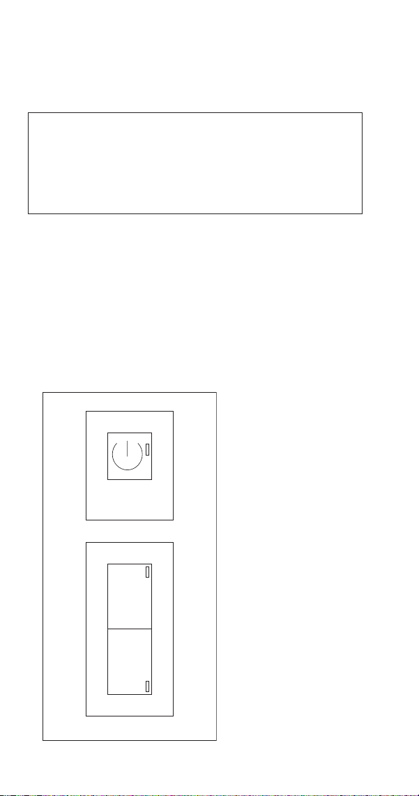
Electronic Timer, Power, Wash, Defrost Switch
The ice machine switch is used to select and control the ice
machine cycles.
n
Warning
Risk of electrical shock or burns. The ice machine front
panel requires removal to access the defrost and wash
buttons. Do not touch electrical wiring or insert hands
into the area the front panel covered.
ON/OFF Push button (1) Used to turn on and turn off the
ice machine - Green LED (2)
DEFR Push button (3) Used to start the defrost cycle -
Yellow LED (4)
WASH Push button (5) Push to start and/or finish the
washing cycle - Blue LED (6)
Refer to “Service Faults” on page 61 for diagnostics.
WASH
W
DEFR
D
12
34
56
1. On/Off Push Button
2. Green Power LED
3. Defrost Push
Button
4. Yellow Defrost LED
5. Wash Push Button
6. Blue Wash LED

Part Number STH106 8/20 43
Ice Cube Thickness Check
The ice cube thickness is factory-set to maintain the ice
cube thickness at the proper size and weight.
NOTE: A dimple in the end of each cube is normal.
Adjusting to remove the dimple will result in longer freeze
cycles and lower production.
1. Allow the ice machine to operate for three complete
cycles. The cubes should have a small dimple in the
center.
2. Cycle times vary, according to surrounding air and
water inlet temperatures.
3. If cubes are not full (large dimple), turn evaporator
thermostat one increment towards the right to
increase cube size. Allow ice machine to complete
three cycles. Check cube.
4. If cubes are too full, (no dimple), turn evaporator
thermostat one increment towards the left to
decrease cube size. Allow ice machine to operate
three complete cycles.
Ice Cube Weight Adjustment
“The factory setting for the evaporator thermostat is 3.
The cube weight can be increased or decreased from the
factory setting by adjusting the evaporator thermostat.
Turn the thermostat to the left to decrease the cube
weight or to the right to increase the cube weight.
NOTE: To access the bin thermostat or adjust cube weight,
remove the front ice machine panel.
Important
Individual cube weight must be between 21 to 24
grams (.75 - .85 oz) to maximize production and
energy efficiency.

44 Part Number STH106 8/20
Bin Thermostat Adjustment
The bin thermostat stops the ice machine when the bin is
full. Turn the thermostat to the left to decrease the level of
ice in bin or to the right to increase the level of ice in bin.
If the ice machine stops before the bin is full or runs after
the bin is full, ambient temperatures are probably high or
low and the bin thermostat can be adjusted.
Removal from Service/Long Term Storage
GENERAL
Special precautions must be taken if the ice machine is to
be removed from service for an extended period of time or
exposed to ambient temperatures of 32°F (0°C) or below.
Step 1 Perform a cleaning and sanitizing procedure to
prevent mildew growth.
Step 2 Disconnect the electric power cord.
Step 3 Turn off the water supply.
Step 4 Drain water from sump by opening/removing
shutters and ice cube slide and then removing overflow
pipe located in the right hand rear corner.
Step 5 Disconnect and drain the incoming ice-making
water line at the rear of the ice machine.
Step 6 Disconnect vinyl hose from water pump and
allow to drain.
Step 7 Make sure water is not trapped in any of the
water or drain lines. Compressed air can be used to blow
out the lines.
Step 8 Block the door partially open to provide air
exchange and prevent mildew growth.

Part Number STH106 8/20 45
Electronic Timer Diagnostics
ICE MACHINE IS NOT RUNNING
GREEN LIGHT IS ENERGIZED
• Refer to bin thermostat diagnostics
GREEN LIGHT IS ENERGIZED AND YELLOW DEFROST
LIGHT FLASHES ONCE EVERY 4 SECONDS
• Freeze time exceeded 90 minutes
• Refer to evaporator thermostat diagnostics
• Refer to refrigeration system diagnostics
GREEN LIGHT IS ENERGIZED AND YELLOW DEFROST
LIGHT FLASHES TWICE EVERY 4 SECONDS
• Harvest time exceeded 30 minutes
• Refer to evaporator thermostat diagnostics
Troubleshooting

46 Part Number STH106 8/20
Troubleshooting
DIAGNOSING AN ICE MACHINE THAT WILL NOT RUN
n
Warning
High (line) voltage is applied to the control board at
all times.
1. Verify primary voltage is supplied to ice machine and
the fuse/circuit breaker is closed.
2. Verify power button functions properly - Refer to
“Electronic Timer” on page 59
3. Verify the bin thermostat is operating correctly - Refer
to “Bin Thermostat” on page 62.
4. Verify line voltage is present on electronic timer
terminals 8 & 12 four minutes after startup- Refer to
“Bin Thermostat” on page 62.

Part Number STH106 8/20 47
DIAGNOSING AN ICE MACHINE THAT DOES NOT CYCLE
INTO HARVEST
1. Verify evaporator temperature is below 7F.
2. Verify the evaporator thermostat is operating
correctly - Refer to “Evaporator Thermostat” on page
63
3. Verify line voltage is present on electronic timer
terminals 8 & 12 four minutes after startup- Refer to
“Bin Thermostat” on page 62.
4. Verify 800 seconds has passed after the evaporator
thermostat has closed.
5. Voltage on electronic timer terminals 7 & 12?
• Yes - Repair wiring
• No - Replace electronic timer

48 Part Number STH106 8/20
DIAGNOSING AN ICE MACHINE THAT CYCLES INTO
HARVEST PREMATURELY
1. Verify evaporator temperature is below 7°F and
before the 800 second finishing timer has expired - If
800 seconds have not passed and a harvest cycle
starts, replace the electronic timer.
2. Evaporator temperature is below 7°F and after the
800 second finishing timer has expired - Refer to
“Water System Checklist” on page 50 as this is an
ice release problem.
3. Adjusting evaporator thermostat keeps the ice
machine in the freeze cycle - Refer to “Evaporator
Thermostat” on page 63
• No - Replace thermostat
• Yes - Adjust thermostat for correct operation

Part Number STH106 8/20 49
ELIMINATE ALL NON REFRIGERATION PROBLEMS
BEFORE DIAGNOSING THE REFRIGERATION SYSTEM.
• Perform a visual inspection for clearances, drains, dirty
condenser/filter and water filter replacement.
• Verify water spray is even across the entire evaporator.
• Run an ice production check - Ice production checks
within 10% are considered normal.
INSTALLATION/VISUAL INSPECTION CHECKLIST
Ice machine is not level
• Level the ice machine
Condenser is dirty
• Clean the condenser
Water filtration is plugged (if used)
• Install a new water filter
Water drains are not run separately and/or are not
vented
• Run and vent drains according to the Installation
Manual

50 Part Number STH106 8/20
WATER SYSTEM CHECKLIST
A water-related problem often causes the same symptoms
as a refrigeration system component malfunction.
Example: Water loss during the freeze cycle, a system low
on charge, and a restricted Capillary tube have similar
symptoms.
Water system problems must be identified and eliminated
prior to replacing refrigeration components.
Water area (evaporator) is dirty
• Descale as needed
Water inlet pressure not between 20 and 80 psig (1–5 bar,
138–552 kPa)
• Install a water regulator valve or increase the water
pressure
Incoming water temperature is not between 50°F (10°C)
and 90°F (32°C)
• If too hot, check the hot water line check valves in
other store equipment
Water filtration is plugged (if used)
• Install a new water filter
Hoses, fittings, etc., are leaking water
• Repair/replace as needed
Water valve is stuck open, closed or is leaking
• Descale/replace as needed
Water is spraying out of the sump trough area
• Stop the water spray
Uneven water flow across the evaporator
• Descale the ice machine
Plastic extrusions and gaskets are not secured to the
evaporator
• Remount/replace as need.

Part Number STH106 8/20 51
ICE FORMATION PATTERN
Evaporator ice formation pattern analysis is helpful in ice
machine diagnostics.
Analyzing the ice formation pattern alone cannot diagnose
an ice machine malfunction. However, when this analysis is
used along with the “Freeze Cycle Analysis Chart” on page
56, it can help diagnose an ice machine malfunction.
Normal Ice Formation
Ice forms across the entire evaporator surface.
At the beginning of the Freeze cycle, it may appear that
more ice is forming on the inlet of the evaporator than at
the outlet. At the end of the Freeze cycle, ice formation at
the outlet will be close to ice formation at the inlet.
If ice forms uniformly across the evaporator surface, but
does not do so in the proper amount of time, this is still
considered a normal ice fill pattern.
Extremely Thin at Evaporator Outlet
There is no ice, or a considerable lack of ice formation on
the outlet of the evaporator.
Examples: No ice at all at the outlet of the evaporator, but
ice forms at the inlet half of the evaporator. Or, the ice at
the outlet of the evaporator reaches the correct thickness,
but the inlet of the evaporator already has thick ice.
Possible cause: Water loss, low on refrigerant, restricted
capillary tube, hot water supply or leaking water inlet
valve.

52 Part Number STH106 8/20
Extremely Thin at Evaporator Inlet
There is no ice, or a considerable lack of ice formation at
the inlet of the evaporator. Examples: The ice at the outlet
of the evaporator reaches the correct thickness, but there
is no ice formation at all at the inlet of the evaporator.
Possible cause: Obstructed nozzles, Insufficient water flow,
incorrect refrigerant charge.
Spotty Ice Formation
There are small sections on the evaporator where there is
no ice formation. This could be a single corner, or an area
of the evaporator.
Possible cause: Obstructed nozzles and the ice machine
requires descaling or tubing separation from the
evaporator.
No Ice Formation
The ice machine operates for an extended period, but
there is no ice formation at all on the evaporator.
Possible cause: Water valve leaking, water pump, capillary
tube, low refrigerant charge, compressor, etc.

Part Number STH106 8/20 53
ICE PRODUCTION CHECK
The amount of ice a machine produces directly relates to
the operating water and air temperatures. This means an
ice machine with a 70°F (21°C) ambient temperature and
50°F (10°C) water produces more ice than the same ice
machine with 90°F (32°C) ambient and 70°F (21°C) water.
1. Determine the ice machine operating conditions:
Air temp entering condenser:____°
Air temp around ice machine:____°
Water temp entering sump trough:____°
2. Refer to the “Cycle Times, 24 Hr. Ice Production and
Refrigerant Temperature Charts” on page 79. Use
the operating conditions determined in Step 1 to find
published 24-Hour Ice Production:_____
• Times are in minutes.
Example: 1 min. 15 sec. converts to 1.25 min.
(15 seconds ÷ 60 seconds = .25 minutes)
• Weights are in pounds.
Example: 2 lb. 6 oz. converts to 2.375 lb.
(6 oz. ÷ 16 oz. = .375 lb.)

54 Part Number STH106 8/20
3. Perform an ice production check using the formula
below.
1. + =
Freeze
Time
Harvest Time Total Cycle
Time
2. 1440 ÷ =
Minutes in
24 Hrs.
Total Cycle
Time
Cycles per Day
3. x =
Weight
of One
Harvest
Cycles per
Day
Actual 24-Hour
Production
Weighing the ice is the only 100% accurate check.
4. Compare the results of step 3 with step 2. Ice
production is normal when these numbers match
closely. If they match closely, determine if:
• Another larger ice machine is required.
• Relocating the existing equipment to lower the
load conditions is required.
Contact the local Manitowoc distributor for information on
available options and accessories.

Part Number STH106 8/20 55
Refrigeration System Diagnostics
R290 (Propane) refrigerant ice machines have a minimal
refrigerant charge in them. Due to the nature of R290
we recommend diagnosing refrigeration problems by
temperature first. For this reason, refrigeration access
fittings are not installed during production and the ice
machine should be diagnosed with temperatures and then
pressure if necessary.
REFRIGERATION DIAGNOSTIC PROCEDURE
1. Verify that your water spray pattern covers the
entire evaporator before diagnosing the refrigeration
system. Mineral buildup can cause nozzle blockage,
water tracking and an erratic ice fill pattern. Descale
with Manitowoc Ice Machine cleaner to remove any
mineral buildup before diagnosing the refrigeration
system.
2. Install and insulate temperature leads: Digital
thermometers with remote insulated thermocouples
must be used to obtain temperatures.
• Suction line within 4” of the compressor.
• Discharge line within 4” of the compressor.
• Harvest valve within 4” of the inlet.
3. All doors and panels must be in place during the
diagnostic procedure.
4. Refer to the “Cycle Times, 24 Hr. Ice Production and
Refrigerant Temperature Charts” on page 79 to
determine the correct operating temperature range
for your air and water temperature. Normal operating
temperatures will be within 10% of the data in the
charts.
5. The first cycle is not used for refrigeration system
diagnostics. Start monitoring temperatures 3
minutes into the second freeze cycle and record the
temperatures throughout the freeze and harvest
cycles.

56 Part Number STH106 8/20
FREEZE CYCLE ANALYSIS CHART
Discharge
Temperature
Evaporator Outlet
Temperature
Freeze Time Harvest Valve
Inlet Temperature
Evaporator Ice
Formation
Evaporator Inlet
Colder Than Outlet
Final Analysis
Enter number of boxes
checked in each row
Lower Than
Normal
Higher Than
Normal
Longer Than
Normal
Higher Than
Normal
Thin on Inlet or
Normal
No Harvest Valve Leaking
Lower Than
Normal
Lower Than
Normal
Shorter Than
Normal
Normal Normal
or Thick On
Outlet
No Overcharged
Normal Higher Than
Normal
Longer Than
Normal
Normal Thin On Outlet
or No Ice
Yes Restricted Capillary Tube
Or Low On Charge
Normal Higher Than
Normal
Longer Than
Normal
Normal Normal or No Ice Yes Compressor
Restricted Capillary/Low on Charge and Compressor diagnostics should be verified by pressure prior to replacement.
See“Cycle Times, 24 Hr. Ice Production and Refrigerant Temperature Charts” on page 79

Part Number STH106 8/20 57
DISCHARGE LINE TEMPERATURE
Maximum compressor discharge line temperature on
a normally operating ice machine steadily increases
throughout the freeze cycle. Compare the maximum
discharge line temperature with the published discharge
line temperature. Discharge line temperature must be
equal or higher than the published temperature.
SUCTION LINE TEMPERATURE
The actual suction temperature changes throughout the
freeze cycle. Determine if the suction line temperature
is within the range listed in “Cycle Times, 24 Hr. Ice
Production and Refrigerant Temperature Charts” on page
79.
LEAKING HARVEST VALVE
The inlet to the harvest valve temperature will be the same
temperature as the discharge line after 8 minutes into the
freeze cycle.
OVERCHARGED SYSTEM SYMPTOMS
Suction and discharge line temperature will be low during
the freeze cycle. Overcharge diagnosis can be difficult.
R290 ice machines ship without access valves; Look for
signs that an access valve has previously been added.
When an overcharge is suspected remove the refrigerant
and weigh in the correct refrigerant amount.

58 Part Number STH106 8/20
RESTRICTED CAPILLARY TUBE/LOW REFRIGERANT
CHARGE SYMPTOMS
• A failed capillary tube or low refrigerant charge will
have a suction line temperature higher than normal
and a normal discharge line temperature.
• A failed capillary tube will not effect the discharge line
temperature during the harvest cycle. A low freeze
and discharge line temperature in the freeze cycle with
a normal harvest cycle discharge line temperature
indicates a failed capillary tube.
• Low refrigerant charge will have both the suction and
discharge line temperatures lower than normal in the
freeze and harvest cycles.
Diagnosis can be confirmed by installing a temporary
access valve and adding 2 oz (57 g) of refrigerant: If the
suction line temperature drops or the ice fill pattern on the
top two rows fills in, the ice machine is low on refrigerant.
Refer to charging procedures for access valve installation/
removal procedure.
HIGHER THAN NORMAL FREEZE CYCLE
TEMPERATURES
• A dirty filter or condenser will result in higher than
normal temperatures. Always clean the filter and
condenser before diagnosing the refrigeration system.
• Hot water entering the ice machine will result in high
suction and discharge line temperatures in the freeze
cycle.
• Inefficient Compressor
Suction and discharge temperatures will be slightly
high to high during the freeze cycle. Remove
refrigerant and weigh in the correct refrigerant
amount. If the ice machine continues to exhibit
symptoms, monitor the discharge line temperature for
a continued increase of temperature. When the ice
machine continues to make ice slowly (or makes little
to no ice and trips the internal compressor overload)
the compressor will require replacement.
Part Number STH106 8/20 59
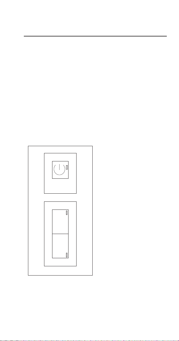
Electronic Timer
POWER, WASH, DEFROST SWITCH
Function
The electronic timer is used to select and control the ice
machine cycles.
ON/OFF Push button (1) Used to turn on and turn off the
ice machine - Green LED (2)
DEFR Push button (3) Used to start the defrost cycle -
Yellow LED (4)
WASH Push button (5) Push to start and/or finish the
washing cycle - Blue LED (6)
1. On/Off Push Button
2. Green Power LED
3. Defrost Push Button
4. Yellow Defrost LED
5. Wash Push Button
6. Blue Wash LED
WASH
W
DEFR
D
12
34
56
Component Check Procedures

60 Part Number STH106 8/20
Check For Normal Operation
Start the ice machine using the following procedure:
1. Press the power button, the Green LED will go out.
2. Press the power button, the Green LED will illuminate
and the ice machine will perform:
A. Pre-Freeze - Refilling of water sump, harvest
cycle
B. Freeze cycle - Compressor starts and water pump
sprays water onto the evaporator
C. Harvest cycle - Harvest valve opens and ice
releases from the evaporator
D. Full bin or Pre-Freeze - Bin Thermostat stops the
ice machine with ice contact or starts another
Freeze cycle

Part Number STH106 8/20 61
Service Faults
Re-start the ice machine using the following procedure and
allow the ice machine to run to determine if the condition
repeats.
Service Fault LED Solution
The ice machine
remains in the
freeze cycle for more
than 90 minutes.
Yellow light flashes
once every 4
seconds
Verify evaporator
thermostat is
operating correctly.
Refer to refrigeration
diagnostics and
check for loss of
refrigerant
The ice machine
remains in the
harvest cycle for
more than 30
minutes.
Yellow light flashes
twice every 4
seconds
Verify evaporator
thermostat is
operation correctly.
The ice machine
does not run, the
bin is empty and
the Green LED is
energized
Green LED is
energized
Verify bin
thermostat is
operating correctly
Note - Removal of the lower front panel is required to view the
yellow LED

62 Part Number STH106 8/20
BIN THERMOSTAT
Function
The bin thermostat stops the ice machine when the bin is
full. The level of ice in the ice storage bin controls the ice
machine shut-off. When the bin is full, ice cubes contact
the bin thermostat bulb holder, which cools down and
opens the bin thermostat to stop the ice machine. The ice
machine remains off until enough ice has been removed
from the bin. This causes the thermostat bulb holder to
warm and closes the bin thermostat, restarting the ice
machine.
Check Procedure
n
Warning
Disconnect electrical power to the entire ice machine
before proceeding.
1. Disconnect power to the ice machine.
2. Disconnect both wires from the bin thermostat
and check the resistance across the bin thermostat
terminals.
No Ice on Bulb Ice on Bulb Result
Contacts Closed Contacts Open Thermostat is Good
Contacts Open Contacts Closed Replace Thermostat
NOTE: After covering/uncovering the bulb holder with
ice, wait at least three minutes to allow the thermostat to
react (Open/Close).
Adjusting
If the ice machine stops before the bin is full or runs after
the bin is full, ambient temperatures are probably high or
low and the bin thermostat will need to be adjusted.
Turn the thermostat to the left to decrease the level of ice
before automatic shut-off. Turn to the right to increase the
level of ice before automatic shut-off.

Part Number STH106 8/20 63
EVAPORATOR THERMOSTAT
Function
The evaporator thermostat changes position as the ice
machine evaporator temperature changes.
Specifications
Constant Cut-In (Close) Factory Setpoint
39°F- 4° C #3 7°F - 14° C
SPDT - Contacts 3 & 2 close on drop - Contacts 3 & 4 close on rise
Adjusting clockwise increases differential
Check Procedure
n
Warning
Disconnect electrical power to the entire ice machine
before proceeding.
1. Disconnect power to the ice machine.
2. Disconnect the three wires from the evaporator
thermostat and check the resistance across the
evaporator thermostat terminals.
No Ice on Bulb Ice on Bulb Result
Contacts Closed Contacts Open Thermostat is Good
Contacts Open Contacts Closed Replace Thermostat

64 Part Number STH106 8/20
FAN CYCLE CONTROL
Function
Cycles the fan motor on and off to maintain proper
operating discharge pressure.
The fan cycle control closes on an increase, and opens on a
decrease in discharge pressure.
Specifications
Cut-In (Close) Cut-Out (Open)
230 psig 190 psig
Check Procedure
1. Disconnect electrical power to the ice machine at the
electrical service disconnect.
2. Verify fan motor windings are not open or grounded,
and fan spins freely.
3. Connect manifold gauge to ice machine.
4. Hook voltmeter in parallel across the fan cycle control,
leaving wires attached.
5. Reconnect electrical power to the ice machine and
press the power button to ON.
6. Wait until water flows over the evaporator then refer
to chart below.
System Pressure: Reading Should Be: Fan Should Be:
Above cut-in 0 volts Running
Below cut-out Line voltage Off

Part Number STH106 8/20 65
COMPRESSOR ELECTRICAL DIAGNOSTICS
The compressor does not start or will trip repeatedly on
overload.
Check Resistance (Ohm) Values
NOTE: Compressor windings can have very low ohm
values. Use a properly calibrated meter.
Perform the resistance test after the compressor cools. The
compressor dome should be cool enough to touch (below
120°F/49°C) to ensure that the overload is closed and the
resistance readings will be accurate.
Single Phase Compressors
1. Disconnect power from the condensing unit and
remove the wires from the compressor terminals.
2. The resistance values between C and S and between
C and R, when added together should equal the
resistance value between S and R.
3. If the overload is open, there will be a resistance
reading between S and R, and open readings between
C and S and between C and R. Allow the compressor
to cool, then check the readings again.
Check Motor Windings to Ground
Check continuity between all three terminals and the
compressor shell or copper refrigeration line. Scrape metal
surface to get good contact. If continuity is present, the
compressor windings are grounded and the compressor
should be replaced.
To determine if the compressor is seized check the amp
draw while the compressor is trying to start.

66 Part Number STH106 8/20
Compressor Drawing Locked Rotor
The two likely causes of this are:
• Defective starting component
• Mechanically seized compressor
To determine which you have:
1. Install high and low side gauge.
2. Try to start the compressor.
3. Watch the pressures closely.
• If the pressures do not move, the compressor is
seized. Replace the compressor.
• If the pressures move, the compressor is turning
slowly and is not seized. Check the capacitors and
relay.
Compressor Drawing High Amps
The continuous amperage draw on start-up should not be
near the maximum fuse size indicated on the serial tag.
The wiring must be correctly sized to minimize voltage
drop at compressor start-up. The voltage when the
compressor is trying to start must be within ±10% of the
nameplate voltage.

Part Number STH106 8/20 67
Filter-Driers
Liquid Line Filter Drier
The filter-drier used on Manitowoc ice machines are
manufactured to Manitowoc specifications.
The difference between a Manitowoc drier and an off-
the-shelf drier is in filtration. A Manitowoc drier has
dirt-retaining filtration, with fiberglass filters on both the
inlet and outlet ends. This is very important because ice
machines have a back-flushing action that takes place
during every harvest cycle.
A Manitowoc filter-drier has a very high moisture removal
capability and a good acid removal capacity.
Important
The liquid line drier is covered as a warranty part. The
liquid line drier must be replaced any time the system
is opened for repair.

68 Part Number STH106 8/20
Flammable Refrigerant Procedures
Servicing Requirements
• It is recommended that only technicians specifically
trained in handling flammable refrigerants, service
or dispose of equipment containing hydrocarbon
refrigerants.
• Color-coded red process tubes indicate use of a
flammable refrigerant - Process tubes must be
replaced after brazing or other service procedures.
• An accessible fire extinguisher is required when
brazing.
• A combustible gas leak detector with a minimum
sensitivity of 8 grams per cubic meter is required. The
meter must be on while servicing the equipment.
Place the detector on the floor and set the detector to
beep at approximately heart beat rate.
• Equipment using hydrocarbon refrigerants have fittings
unique to flammable refrigerants.
• Work in well-ventilated, open spaces - A ventilation fan
can be used to disperse any residual refrigerant. Place
the fan a minimum of 10’ (3m) away from the work
area.
• Eliminate all ignition sources.
• The filter drier must be replaced whenever the system
is opened to the atmosphere.
Important
• Remove piercing valves after charging.
• Unit is critically charged. Nitrogen must be purged
through the system while brazing to prevent build up
of copper oxide in the refrigeration system.
• Manifold gauge set must be removed properly to
ensure that no refrigerant contamination or loss
occurs. A quick disconnect is required for the high
side connection.

Part Number STH106 8/20 69
REFRIGERANT PURGING REQUIREMENTS
NOTE: Country and Local Codes for removal and processing
of this refrigerant must always take precedence over these
procedures.
• Minimum of 10 feet from building, verify wind
direction will not introduce refrigerant into building
• Verify refrigerant does not enter buildings through
intake air vents
• Although not required hydrocarbon refrigerants can be
recovered, instead of venting to the atmosphere.
• Purge system with dry nitrogen to displace any trapped
propane.
DANGER
Disconnect all electric power to the system. Shorting
electrical wires to refrigeration tubing may result in an
explosion.

70 Part Number STH106 8/20
REFRIGERANT PURGING PROCEDURE
1. Disconnect all electric power to the system and
lockout tag out the power source(s).
NOTE: Some systems may have more than one power
supply.
2. Work in well-ventilated, open space and eliminate all
ignition sources.
3. Install piercing valves on the high and low side access
fittings.
4. Attach manifold gauge set to the low and high side
fittings. Hoses need to be as short as practical, due to
the small refrigerant charge.
5. Purge refrigerant from both low and high side.
6. Purge the system with dry nitrogen for 3 minutes.
7. Evacuate the system with a vacuum pump
8. Purge the system again with dry nitrogen
9. Open the system by cutting the tubes with a tube
cutter. Do not use a torch to open the system.
BRAZING PROCEDURE
10. Always purge nitrogen whenever using a torch. The
nitrogen pressure regulator must be equipped with
two gauges; One gauge to measure the cylinder
pressure, and one to measure the discharge
(refrigeration system psig). The pressure regulator
must be capable of reducing the pressure to 2 or 3
psig and steadily maintaining this pressure.

Part Number STH106 8/20 71
PRESSURE TESTING
11. Pressure test with dry nitrogen to detect leaks. Use
nitrogen and a trace amount of refrigerant to locate
the leak if a pressure test indicates a leak is present.
12. Do not over pressurize the system. Check the name
plate for the maximum test pressure.
DANGER
Failure to properly purge or pressure test a system
for leaks, can result in serious injury or death from
explosion, fire, or contact with refrigerant or lubricant
mists.
EVACUATION
13. Slowly release the nitrogen and evacuate to a
minimum of 500 microns.
NOTE: Do not start the compressor while it is in a vacuum
or energize the compressor with the terminal cover off.
Always break a vacuum with refrigerant before energizing
(starting) the compressor.

72 Part Number STH106 8/20
Refrigerant Charging
Due to the small refrigerant quantities, a cap tube in the
.50 to .85 ID range with a shutoff valve at the access port
can be used to control the flow of refrigerant. The charge
accuracy must be within +/- 1% of the nameplate listed
charge.
14. Invert the charging bottle, and place on a scale
capable of reading grams and ounces.
15. Purge liquid refrigerant to the shutoff valve, then zero
out the scale and allow the reading to settle.
NOTE: It is important that the scales and hoses are
positioned so that they will not be disturbed when adding
refrigerant.
Important
The charge is critical on all Manitowoc ice machines.
Use a scale to ensure the proper charge is installed.
A quick disconnect is required for the high side
connection
16. Add refrigerant through the high side and close the
valve just before the nameplate refrigerant amount is
reached, then add refrigerant to reach the final charge
amount. If all of the refrigerant can not be added to
the high side, the remainder can be added as vapor to
the low side while the compressor is running.
17. Press the power button.

Part Number STH106 8/20 73
NOTE: Manifold gauge set must be removed properly to
ensure no refrigerant contamination or loss occurs.
18. Verify all of the vapor in the charging hoses is drawn
into the refrigeration system before disconnecting the
charging hoses.
A. Run the ice machine in freeze cycle.
B. Remove the high side low loss fitting.
C. Open the high and low side valves on the
manifold gauge set. Any refrigerant in the lines
will be pulled into the low side of the system.
D. Allow the suction pressures in the refrigeration
system and the manifold gauge set to equalize
while the ice machine is in the freeze cycle.
E. Isolate and remove the low side hose.
19. Use a pinch-off tool on the access fitting and remove
temporary access valves and seal the refrigeration
system.

74 Part Number STH106 8/20
System Contamination Cleanup
This section describes the basic requirements for restoring
contaminated systems to reliable service.
DETERMINING SEVERITY OF CONTAMINATION
System contamination is generally caused by either
moisture or residue from compressor burnout entering the
refrigeration system.
Inspection of the refrigerant usually provides the first
indication of system contamination. Obvious moisture or
an acrid odor in the refrigerant indicates contamination.
If either condition is found, or if contamination is
suspected use a test kit.
If a refrigerant test kit indicates harmful levels of
contamination, or if a test kit is not available, inspect the
compressor oil.
1. Remove the refrigerant charge from the ice machine.
2. Remove the compressor from the system.
3. Check the odor and appearance of the oil.
4. Inspect open suction and discharge lines at the
compressor for burnout deposits.
5. If no signs of contamination are present, perform
an acid oil test to determine the type of cleanup
required.

Part Number STH106 8/20 75
Contamination/Cleanup Chart
Symptoms/Findings Required Cleanup
Procedure
No symptoms or suspicion of
contamination
Normal evacuation/
recharging
procedure
Moisture/Air Contamination symptoms
Refrigeration system open to atmosphere
for longer than 15 minutes
Refrigeration test kit and/or acid oil test
shows contamination
No burnout deposits in open compressor
lines
Mild contamination
cleanup procedure
Mild Compressor Burnout symptoms
Oil appears clean but smells acrid
Refrigeration test kit or acid oil test shows
harmful acid content
No burnout deposits in open compressor
lines
Mild contamination
cleanup procedure
Severe Compressor Burnout symptoms
Oil is discolored, acidic, and smells acrid
Burnout deposits found in the compressor,
lines, and other components
Severe
contamination
cleanup procedure

76 Part Number STH106 8/20
MILD SYSTEM CONTAMINATION CLEANUP
PROCEDURE
1. Replace any failed components.
2. If the compressor is good, change the oil.
3. Replace the liquid line drier.
NOTE: If the contamination is from moisture, use heat
lamps during evacuation. Position them at the compressor,
condenser and evaporator prior to evacuation. Do not
position heat lamps too close to plastic components, or
they may melt or warp.
4. Follow the normal evacuation procedure, except
replace the evacuation step with the following:
A. Pull vacuum to 1000 microns. Break the vacuum
with dry nitrogen and sweep the system.
Pressurize to a minimum of 5 psig.
B. Pull vacuum to 500 microns. Break the vacuum
with dry nitrogen and sweep the system.
Pressurize to a minimum of 5 psig.
C. Change the vacuum pump oil.
D. Pull vacuum to 500 microns. Run the vacuum
pump for 1/2 hour on self-contained models, 1
hour on remotes.
NOTE: You may perform a pressure test as a preliminary
leak check. You should use an electronic leak detector after
system charging to be sure there are no leaks.
5. Charge the system with the proper refrigerant to the
nameplate amount.
6. Operate the ice machine.

Part Number STH106 8/20 77
SEVERE SYSTEM CONTAMINATION CLEANUP
PROCEDURE
1. Remove the refrigerant charge.
2. Remove the compressor.
3. If burnout deposits are found, replace the capillary
tube.
4. Wipe away any burnout deposits from suction and
discharge lines at compressor.
5. Sweep through the open system with dry nitrogen.
6. Install a new compressor and new start components.
7. Install suction line filter-drier in front of compressor.
8. Install a new liquid line drier.
9. Follow the normal evacuation procedure, except
replace the evacuation step with the following:
A. Pull vacuum to 1000 microns. Break the vacuum
with dry nitrogen and sweep the system.
Pressurize to a minimum of 5 psig.
B. Change the vacuum pump oil.
C. Pull vacuum to 500 microns. Break the vacuum
with dry nitrogen and sweep the system.
Pressurize to a minimum of 5 psig.
D. Change the vacuum pump oil.
E. Pull vacuum to 500 microns. Run the vacuum
pump for 1 additional hour.

78 Part Number STH106 8/20
10. Charge the system with the proper refrigerant to the
nameplate charge.
11. Operate the ice machine for one hour. Then, check
the pressure drop across the suction line filter-drier.
A. If the pressure drop is less than 2 psig, the filter-
drier should be adequate for complete cleanup.
B. If the pressure drop exceeds 2 psig, change the
suction line filter-drier and the liquid line drier.
Repeat until the pressure drop is acceptable.
12. Operate the ice machine for 48 – 72 hours. Replace
the suction line and liquid line drier if necessary.
Total System Refrigerant Charge
Important
This information is for reference only. Refer to the ice
machine serial number tag to verify the system charge.
Serial plate information overrides information listed
on this page.
Model Air-Cooled Refrigerant Type
USP0100A 110 grams (3.9 oz) R290 - Propane

Part Number STH106 8/20 79
Cycle Times, 24 Hr. Ice Production and
Refrigerant Temperature Charts
These charts are used as guidelines to verify correct ice
machine operation.
• Accurate collection of data is essential to obtain the
correct diagnosis. Eliminate all non refrigeration
problems before diagnosing the refrigeration system.
• Perform a visual inspection for clearances, drains, dirty
condenser/filter and water filter replacement.
• Verify water flow is even across the entire evaporator.
• Ice production checks that are within 10% of the chart
are considered normal. This is due to variances in
water and air temperature. Actual temperatures will
seldom match the chart exactly.
• Refer to “Refrigeration diagnostics” for the list of data
that must be collected for refrigeration diagnostics.
Charts
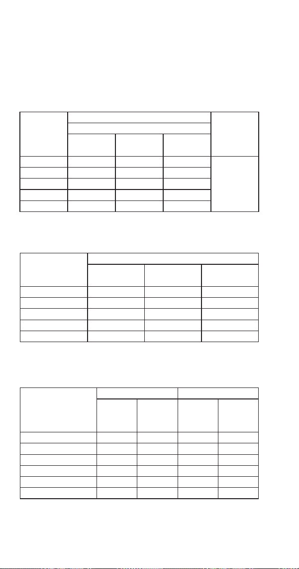
80 Part Number STH106 8/20
USP0100A AIR-COOLED
NOTE: These characteristics may vary depending on
operating conditions.
Cycle Times
Freeze Time + Harvest Time = Total Cycle Time
Air Temp.
Entering
Condenser
°F/°C
Freeze Time Harvest
TimeWater Temperature °F/°C
50/10 70/21 90/32
70°/21° 23-25 26-28 28-30
1.75-3.5
80°/27° 24-26 27-29 30-31
90°/32° 24-25 25-29 29-31
100°/38° 26-28 29-31 32-34
110°/43° 29-31 31-34 35-37
Times in minutes
24 Hour Ice Production
Air Temp.
Entering
Condenser °F/°C
Water Temperature °F/°C
50/10 70/21 90/32
70°/21° 100 95 90
80°/27° 95 94 85
90°/32° 90 93 80
100°/38° 85 85 75
110°/43° 80 75 70
Based on average ice slab weight of 21 to 24 grams (.75 - .85 oz)
Pressure Chart
Air Temperature
Entering Condenser
°F/°C
Freeze Cycle Harvest Cycle
Discharge
Pressure
PSIG
Suction
Pressure
PSIG
Discharge
Pressure
PSIG
Suction
Pressure
PSIG
50°/10° 190-230 38-15 90-115 60-110
70°/21° 190-237 45-15 90-118 60-118
80°/27° 190-238 45-15 90-120 62-120
90°/32° 190-240 45-15 94-135 62-122
100°/38° 210-280 50-17 100-160 65-135
110°/43° 235-310 53-18 110-170 70-138
Part Number STH106 8/20 81
Temperature Chart
Air Temp.
Entering
Condenser °F/°C
Freeze Cycle Harvest Cycle
Discharge
Temperature
Suction
Temperature
Harvest Valve
Inlet
Liquid Line
Temperature
Discharge
Temperature
Evaporator Outlet
Temperature
50°/10° 150-175 55-65 75-80 100-115 100-130 35-55
70°/21° 165-181 58-70 95-100 105-118 105-145 40-60
80°/27° 168-183 58-72 100-105 105-120 110-150 42-80
90°/32° 170-184 62-73 105-110 105-121 112-154 43-88
100°/38° 195-202 72-85 102-130 122-140 120-160 50-97


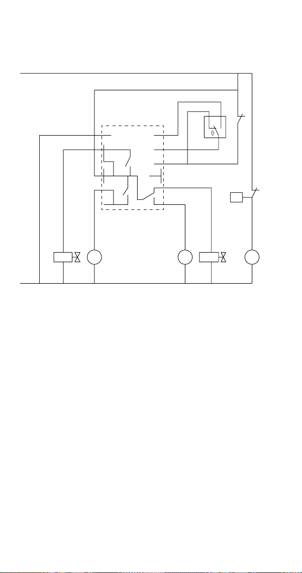

Part Number STH106 8/20 85
1Ph Air-cooled
Number Component
1 Bin Thermostat
2 Evaporator Thermostat
4 Compressor
5 Harvest Valve
6 Water Inlet Valve
7 Water Pump
7a Condenser Fan Motor
10 Fan Cycle Control
52 Electronic Timer
Wire Colors
BK Black
BN Brown
BU Blue
GY Grey
OG Orange
PK Pink
RD Red
VT Violet
RD Red
WH White