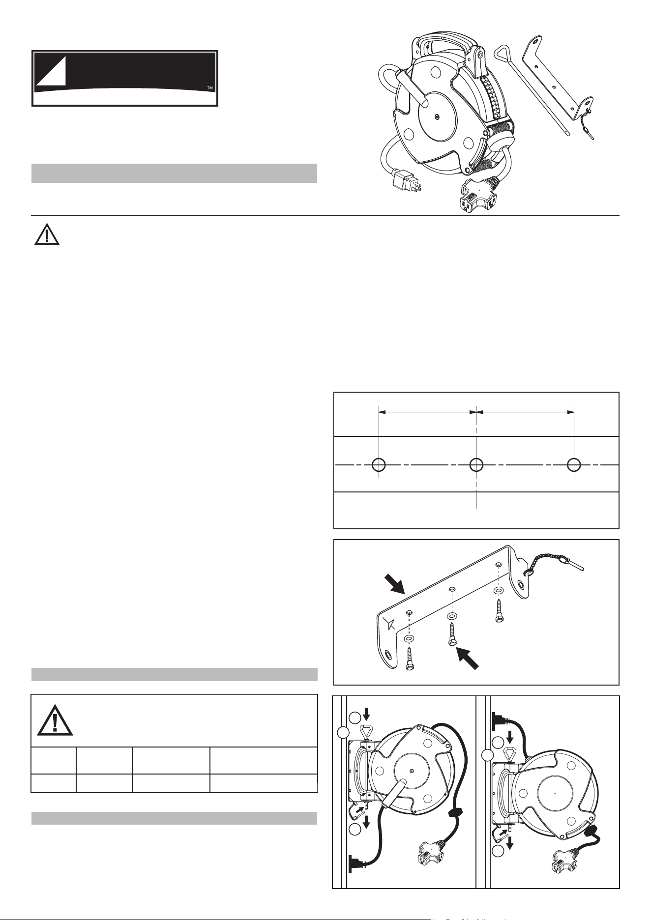
3 1/4“ 3 1/4“
Fig. 1
Bracket hole pattern
3 - #5/16” SCREWS
Bracket A
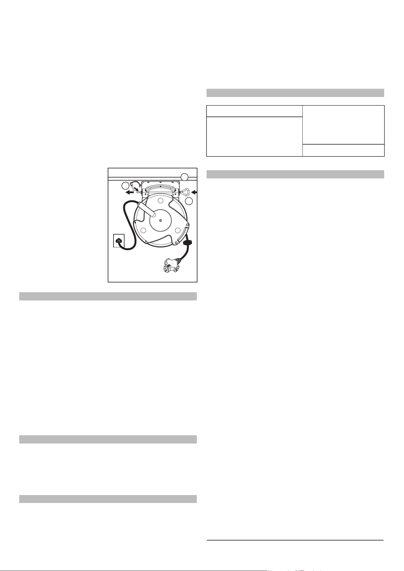
Fig. 2
INSTALLATION
WARNING: To avoid serious injury or death from electrical
shock or fire.
1. DO NOT handle this fixture or try to plug it in when your hands
are wet or damp or when you are standing on a wet or damp
surface or in water.
2. This fixture MUST ALWAYS BE USED in accordance with all
electrical and safety codes and ordinances, including the most
recent National Electric Code (NEC) and with the Occupational
Safety and Health Act (OSHA) Volume 1 on General Industry
Standards and interpretations.
3. ALWAYS make certain that the power source conforms to the
requirements on the fixture.
4. ALWAYS disconnect the power before servicing or inspecting
the fixture for any reason.
5. This fixture IS ONLY FOR USE ON 110-125V and is equipped
with an approved 3 conductor cord with a 3-prong, grounded
plug. TO REDUCE THE RISK OF ELECTRICAL SHOCK, it
should only be plugged into a properly grounded 3-prong outlet.
6. This fixture comes equipped with a 3-prong grounded plug. DO
NOT remove the 3rd prong or otherwise try to modify the plug. If it
will not fit the outlet, have the proper outlet installed by a
qualified electrician. Improper connection of the grounding
conductor can result in a risk of electrical shock.
7. NEVER attempt to plug the fixture into a non-grounded outlet or
extension cord and ALWAYS be sure that the extension cord is in
good electrical condition.
8. FIXTURE IS NOT WATERPROOF and is not intended for use in
showers, saunas or in potentially wet locations. ALWAYS keep
this fixture away from sinks, tubs, showers, etc. NEVER attempt
to pick up plugged-in power tools or appliances should they fall
into standing water. Fatal Electrocution could result!
9. This fixture is intended for use as a general indoor power source.
DO NOT use in potentially dangerous locations, such as in
flammable or explosive atmospheres.
10. Keep away from heating vents, radiators, or other sources of
heat.
11. KEEP OUT OF REACH OF CHILDREN.
Model Cord Length Cord Type/Gauge
Maximum outlet Rating
(Total for 3 outlets)
125V, 10AMP, 1250WATT14/3 SJTOW75FT8675MFT
WARNING: DO NOT OVERLOAD! Check the
amperages of the tools or appliances to be plugged into
the outlets of the extension cord reel. Listed below are
the maximum amperage ratings.
All three screws with washers must be used when installing
mounting bracket. Eliminating one or more of the supplied hex head
screws may allow bracket to detach allowing reel to fall causing
damage to vehicles, injury or death.
1. Pick the approximate location for the reel with 2 1/2 ft of a
110-125V Standard Outlet.
2. Locate a stud to install the mounting bracket. The bracket will be
placed against the wall vertically, directly over the center of the
stud.
3. Using the bracket as a template, mark the (3) screw locations
with pencil. (Fig.1)
4. Pre Drill (Pilot) the three screw holes with the use of at 1/4" drill.
The depth of the Pilot holes should be at least 2".
5 . Install the bracket with the (3) provided head wood screws with
washers using a 1/2" wrench or socket. Tighten all three until
snug.
PROREEL
I N D U STR IAL
OWNER’S INSTRUCTIONS
HEAVY DUTY 75 Ft. Tri-Tap
Extension Cord Reel
CAUTION: Read all instructions and warnings before Operating
SAVE THESE INSTRUCTIONS! READ ALL INSTRUCTIONS!
Model No: 8675MFT
ELECTRICAL RATING
WALL MOUNTING (Fig. 3 & Fig. 4)
Fig. 3
A
B
C
Fig. 4
A
B
C
Wall Mount
5Ft or Below
Wall Mount
Above 5Ft
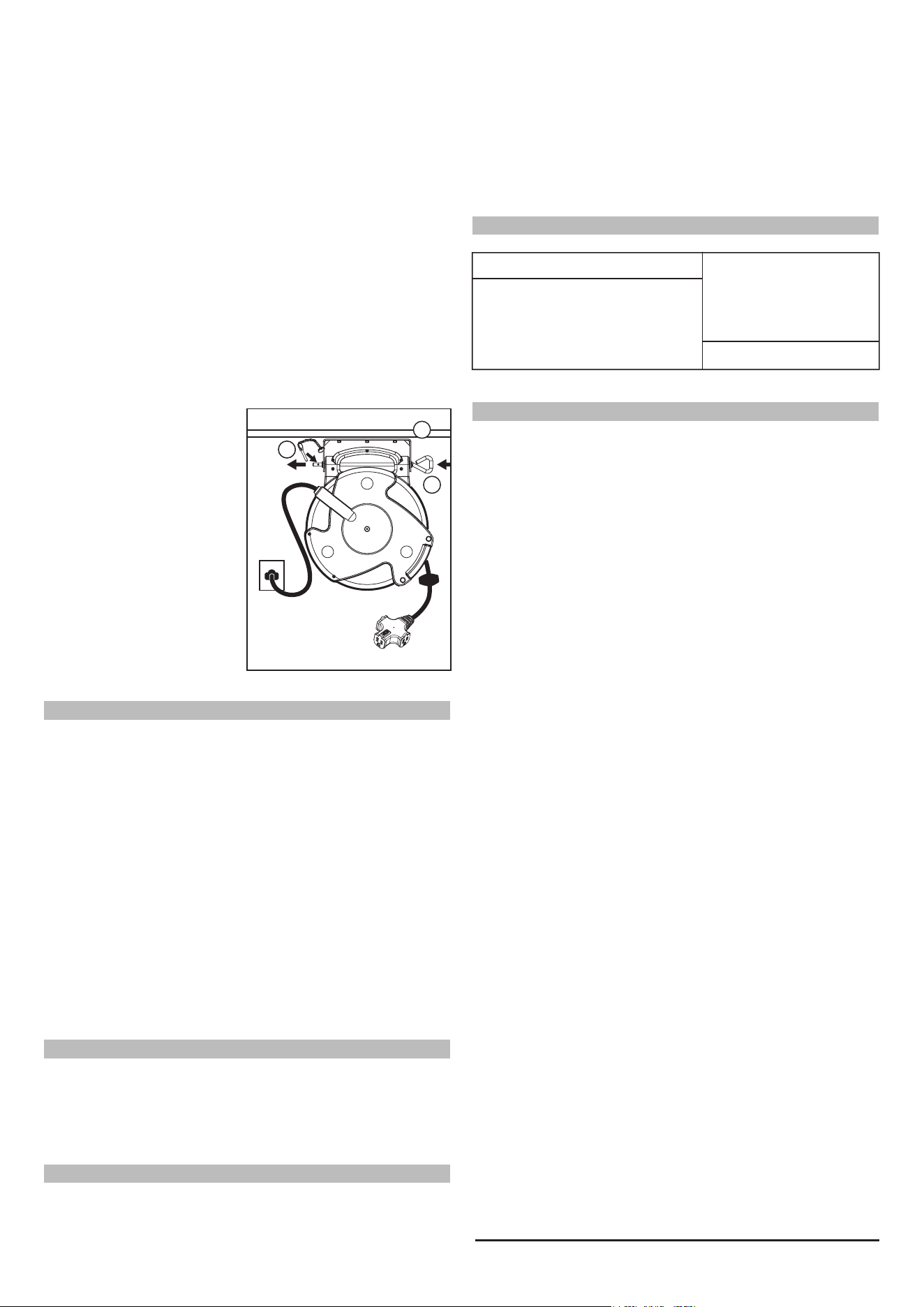
CEILING MOUNTING (Fig. 5)
1. Pick the approximate location for the reel with 2 1/2 ft. of a
110-125V Standard Outlet.
2. Locate a joist or beam to install the mounting bracket. The
bracket should be placed directly over the center of the joist or
beam.
3. Using the bracket as a template, mark the (3) screw locations
with pencil. (Fig.1)
4. Pre Drill (Pilot) the three screw holes with the use of at 1/4" drill.
The depth of the Pilot holes should be at least 2".
5. Install the bracket with the (3) provided head wood screws with
washers using a 1/2" wrench or socket. Tighten all three until
snug.
6. The reel can now be
installed into the bracket.
(Fig.5)
7. Slide the mounting pin (B)
through bracket and reel.
CAUTION: To avoid possible injury. DO NOT allow the cord to fly
unrestricted back into the reel. Guide the cord back into the reel by hand
to control retraction speed.
NOTE: Outlet is un-switched and energized at all time. DO NOT
OVERLOAD !
11/2016
OPERATION
CIRCUIT BREAKER OVERLOAD PROTECTION
MAINTENANCE
Plug power cord into any 110-125V standard wall outlet. The
Power-On Indicator will light indicating the outlets are energized. If
the indicator does not light, check power source. Plug up to three
(3) electrical appliances into the Tri-Tap outlet. The outlet with a
“PUSH” button has the lock plug function. Press the PUSH button
before plug-in, after the plug pins are fully insert to this outlet, then
release the button and the plug is securely locked. To release, press
down the button and un-plug it. Pull cord to approximate desired
length. Continue pulling the cord out slowly. When a clicking sound
is heard, stop pulling the cord. The cord is now locked in place and
is ready for use. To retract, pull the cord out slowly until the clicking
sound stops. The cord is now unlocked and ready to retract fully.
WARNING: Slide the locking
pin (C) thru the Mounting Pin
(B) for security. It will prevent
the mounting pin from sliding
out of position
NOTE: When Ceiling Mounting
is to be against at steel beam, a
Professional Installer should
use minimum 1/4" bolts with
lock washers or locking nuts.
WARNING: UNPLUG UNIT BEFORE PERFORMING ANY MAINTE-
NANCE. Remove dirt and grime as soon as it accumulates. Use a
Alert Stamping & Mfg. Co. Inc.
24500 Solon Road, Bedford Heights. OH 44146 U.S.A.
www.alertstamping.com Toll Free 1-800-400-5020
All ALERT products are individually tested and inspected for defects
in material and workmanship before leaving the factory. Should this
product fail within ONE YEAR due to faulty workmanship or
material, simply return to the original place of purchase for a
replacement. Our ONE YEAR POLICY is limited to the replacement
of the original purchase. No other liability, responsibility or warranty
is expressed or implied, including any fitness for a particular
purpose.
LIMITED ONE YEAR WARRANTY
Fig. 5
A
B
C
REPAIR PARTS LIST
WB-4 Wall Bracket Kit $12.00
(Includes Bracket, Mounting Pin,
3 Hex Head Screws and Washers)
Send check or money
order to:
Alert Parts Department,
24500 Solon Rd.
Bedford Heights, OH 44146
Replacement Parts
Indicate Model & Quantity
soft, damp cloth and a mild soap, if needed. Be sure not to get the
electrical plug wet. NEVER submerge any part of the Cord Reel in
any solution to clean it.DO NOT USE solvents such as gasoline,
turpentine, etc. to clean unit.Keep reel cord clean to assure
smoothest automatic retraction. To clean, simply pull cord to its full
length and allow to retract through a dampened rag. Pull out full
length again and allow to retract through clean rag sprinkled with
talcum powder.
DRY THOROUGHLY BEFORE PLUGGING BACK INTO OUTLET.
6. The reel can now be installed into the bracket. The following
installation instruction will allow smooth retraction:
a. When the mounting height is less than 5 ft, the reel should be
positioned so that the cord opening face upward (Fig. 3).
b. When the mounting height is more than 5 ft, the cord opening
should face downward (Fig. 4).
7. Slide the mounting pin (B) thru bracket and reel. Slide the locking
pin (C) through the Mounting Pin for security.
The reset button for the circuit breaker is located located on the
bottom of the plug. If unit is overloaded circuit breaker will trip (black
resetbutton will pop out).Remove overload, wait two minutes, then
reset by pressing black button.

3 1/4“ 3 1/4“
Fig. 1
Disposition des trous de l'étrier
Vis 5/16 po (x 3)
Étrier A
Fig. 2
Fig. 3
A
B
C
Fig. 4
A
B
C
Montage au mur
à 1,5 m ou moins
Montage au mur
à plus de 1,5 m
INSTALLATION
Modèle Longueur du fil Type/diam. du fil
Valeurs maxi.
(total des 4 prises)
125 V, 10 A, 1 250 W14/3 SJTOW19,8 m8675MFT
AVERTISSEMENT: NE PAS SURCHARGER !
Vérifiez le courant tiré (en ampères) par les outils ou les
appareils qui seront branchés aux prises de la rallonge
de l'enrouleur. Le tableau ci-dessous indique les
valeurs maximales.
Pour poser l'étrier, il faut employer les trois vis et les rondelles. S'il
manquait une ou plusieurs des vis fournies, l'étrier pourrait se
décrocher et la chute de l'enrouleur pourrait provoquer des
dommages, des blessures ou même la mort.
1. Choisir l'endroit de montage de l'enrouleur, à moins de 75 cm
d'une prise normale de 110-125 V.
2. Repérer un montant qui servira au montage de l'étrier. L'étrier
doit être monté au mur verticalement, directement au centre du
montant.
3. En utilisant l'étrier comme gabarit, marquer au crayon
l'emplacement des trois vis (fig. 1).
4. À l'aide d'un perceuse munie d'une mèche de 6 mm, percer des
avant-trous pour les vis. Percer à au moins 5 cm de profondeur.
5. Poser l'étrier à l'aide des trois vis à bois et des rondelles fournies
et d'une clé ou d'une douille de 13 mm. Les serrer fermement.
PROREEL
I N D U STR IAL
Instructions
Rallonge sur 26 m – Trois prises
ULTRAROBUSTE enrouleur
Modèle n° 8675MFT
CARACTÉRISTIQUES ÉLECTRIQUES
MONTAGE AU MUR (fig. 3 et 4)
ATTENTION :
lire toutes les instructions et tous les avertissements avant de se servir de l'appareil !
CONSERVER CES INSTRUCTIONS ! LIRE TOUTES LES INSTRUCTIONS !
1. NE PAS manipuler ou essayer de brancher cet appareil si on a
les mains mouillées ou humides ou si l'on se tient sur une surface
mouillée ou humide ou dans l'eau.
2. Cet appareil DOIT TOUJOURS ÊTRE UTILISÉ conformément
aux codes de l'électricité et de la sécurité pertinents applicables
localement.
3. Il faut TOUJOURS s'assurer que le courant d'alimentation
correspond aux caractéristiques indiquées sur l'appareil.
4. Il faut TOUJOURS débrancher l'appareil avant de l'entretenir ou
de l'inspecter pour une raison quelconque.
5. Cet appareil NE DOIT ÊTRE BRANCHÉ QU'À UNE PRISE
110-125 V CA et est muni d'un fil approuvé à trois conducteurs et
d'une fiche à trois broches avec mise à la terre. POUR RÉDUIRE
LE RISQUE DE CHOC ÉLECTRIQUE, il ne devrait être branché
que dans une prise à trois trous avec mise à la terre.
6. Cet appareil est muni d'une fiche à trois broches avec mise à la
terre. NE PAS enlever la troisième broche ou autrement essayer
de modifier la fiche. Si elle ne pénètre pas dans la prise, faire
poser une prise conforme par un électricien compétent. Le
mauvais branchement du conducteur de mise à la terre peut
provoquer des risques de choc électrique.
7. NE JAMAIS essayer de brancher l'appareil à une prise ou une
rallonge qui n'est pas mise à la terre et TOUJOURS s'assurer
que la rallonge est en bon état électrique.
8. CET APPAREIL N'EST PAS ÉTANCHE et ne doit pas être utilisé
dans une douche, un sauna ou des endroits pouvant être
mouillés. TOUJOURS l'éloigner des éviers, lavabos, douches,
etc. NE JAMAIS essayer de ramasser un outil ou un appareil
électrique branché s'il est tombé dans l'eau car cela pourrait
provoquer une électrocution fatale !
9. Cet appareil est destiné à servir de source d'alimentation
polyvalente à l'intérieur. NE PAS s'en servir dans des locaux
présentant des risques, comme dans des atmosphères
inflammables ou explosives.
10.Éloigner des sorties de chaleur, des radiateurs et autres sources
de chaleur.
11.GARDER HORS DE LA PORTÉE DES ENFANTS.
AVERTISSEMENT: pour éviter des blessures graves ou
même la mort par suite d'un choc électrique ou d'un
incendie :
Alert Stamping & Mfg. Co. Inc.
24500 Solon Road, Bedford Heights. OH 44146 U.S.A.
www.alertstamping.com Sansfrais 1-800-400-5020
Les produits Alert sont inspectés et testés individuellement avant de
quitter l'usine. Si ce produit cessait de fonctionner dans L'ANNÉE
suivant son achat à cause d'un défaut de fabrication ou de matière,
le retourner au point de vente pour le faire remplacer. Notre
GARANTIE D'UN AN se limite au remplacement du produit d'origine.
Aucune autre garantie n'est explicitement ou tacitement offerte et le
fabricant n'assume aucune responsabilité, notamment l'aptitude à
un usage particulier.
AVERTISSEMENT : DÉBRANCHER L'APPAREIL AVANT
D'EFFECTUER TOUT ENTRETIEN. Enlever la saleté et les dépôts
dès qu'ils s'accumulent. Employer un chiffon doux humide et un
savon doux, au besoin. Veiller à ne pas mouiller la prise. NE
JAMAIS submerger une partie quelconque de l'enrouleur dans une
Fig. 5
A
B
C
MONTAGE AU PLAFOND (fig. 5)
1. Choisir l'endroit de montage de l'enrouleur, à moins de 75 cm
d'une prise normale de 110-125 V.
2. Repérer une solive ou une poutre qui servira au montage de
l'étrier. L'étrier doit être monté directement au centre de la
poutre.
3. En utilisant l'étrier comme gabarit, marquer au crayon
l'emplacement des trois vis (fig. 1).
4. À l'aide d'un perceuse munie d'une mèche de 6 mm, percer des
avant-trous pour les vis. Percer à au moins 5 cm de profondeur.
5. Poser l'étrier à l'aide des trois vis à bois et des rondelles fournies
et d'une clé ou d'une douille de 13 mm. Les serrer fermement.
6. L'enrouleur peut maintenant
être posé dans l'étrier (fig. 5).
7. Enfiler la broche de montage
(B) à travers l'étrier et
l'enrouleur.
ATTENTION : pour éviter les risques de blessure, NE PAS lâcher le fil
et le laisser rentrer dans l'enrouler sans le retenir. Guider le fil vers
l'enrouleur en le retenant légèrement.
REMARQUE : les prises n'ont pas d'interrupteur et sont toujours sous
tension. NE PAS LES SURCHARGER !
11/2016
UTILISATION
ENTRETIEN
Brancher le fil d'alimentation dans une prise normale de 110-125 V.
En s'allumant, la Voyant d'alimentation indique que les prises sont
sous tension. Si le voyant ne s'allume pas, vérifier l'alimentation.
On peut brancher jusqu'à trois appareils dans la prise triple. La
prise centrale est verrouillable. Appuyer sur le bouton, insérer la
fiche, puis relâcher le bouton : la fiche sera solidement retenue.
Pour la débrancher, appuyer sur le bouton. Tirer le fil jusqu'à la
longueur voulue. Continuer à le tirer lentement. Quand un "clic" se
fait entendre, arrêter de tirer : la rallonge est maintenant verrouillée
et prête à servir. Pour la réenrouler, tirer la rallonge lentement
jusqu'à ce que le "clic" s'arrête : le fil est maintenant déverrouillé et
peut s'enrouler complètement.
AVERTISSEMENT : verrouiller
la broche de montage (B) avec
la goupille (C), pour éviter que
la broche ne puisse se déplacer.
REMARQUE : si le montage au
plafond se fait sur une poutre en
acier, faire appel à un installa-
teur professionnel, qui devra
employer des boulons d'au
moins 6 mm et des rondelles ou
des écrous autobloquants.
GARANTIE LIMITÉE D'UN AN
PIÈCES DE RECHANGE
WB-4 Trousse étrier mural 12,00 $
(Comprend l'étrier, la broche de
montage, trois vis à tête hexagonale et
trois rondelles)
Envoyer un chèque ou un
mandat à :
Alert Parts Department,
24500 Solon Rd.
Bedford Heights, OH 44146
U.S.A.
Pièces de rechange
Préciser le n° d'article et la quantité
6. L'enrouleur peut maintenant être posé dans l'étrier. Pour que
l'enrouleur fonctionne en douceur, suivre les étapes suivantes :
a. Si l'enrouleur est posé à moins de 1,5 m du sol, l'installer de
manière que la sortie du fil soit vers le haut (fig. 3).
b. Si l'enrouleur est posé à plus de 1,5 m du sol, l'installer de
manière que la sortie du fil soit vers le bas (fig. 4).
7. Enfiler la broche de montage (B) à travers l'étrier et l'enrouleur et
la verrouiller avec la goupille (C).
solution quelconque pour le nettoyer. NE PAS employer de solvants
comme de l'essence, de la térébenthine, etc. pour nettoyer
l'appareil. Conserver le fil propre pour qu'il se rétracte automatique-
ment en douceur. Pour le nettoyer, simplement tirer le fil à sa
longueur maximale et le laisser rentrer en le faisant passer dans un
chiffon humide. Le tirer de nouveau en entier et le faire passer cette
fois à travers un chiffon propre saupoudré de talc.
ASSÉCHER L'APPAREIL COMPLÈTEMENT AVANT DE LE
BRANCHER DE NOUVEAU.
COUPE-CIRCUIT DE PROTECTION
Le bouton de remise à zéro pour le disjoncteur se trouve sur le
brancher du bas. Si l'on surcharge la rallonge, le coupe-circuit se
déclenchera (le bouton de réarmement noir sortira). Débrancher
l'appareil ayant provoqué la surcharge, attendre deux minutes puis
réarmer le coupe-circuit en enfonçant le bouton noir.