NGM 220V-240V
56126.0001 B 12/21 © 2019 Bunn-O-Matic Corporation
INSTALLATION & OPERATING GUIDE
Bunn-O-Matic Corporation
Post Office Box 3227, Springfield, Illinois 62708-3227
Phone (217) 529-6601 | Fax (217) 529-6644
www.bunn.com
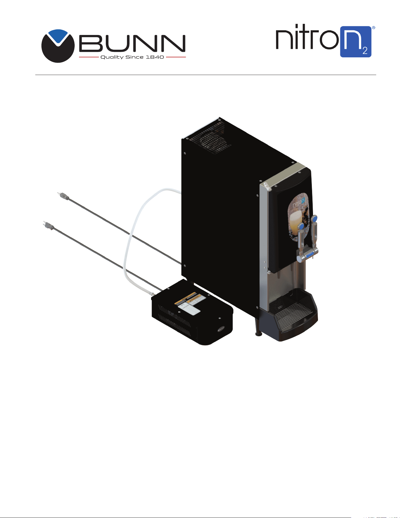
NGM
Nitron Gas Module

2
BUNN-O-MATIC COMMERCIAL PRODUCT WARRANTY
Bunn-O-Matic Corp. (“BUNN”) warrants equipment manufactured by it as follows:
1) Airpots, thermal carafes, decanters, GPR servers, iced tea/coffee dispensers, MCR/MCP/MCA single cup brewers, ther-
mal servers and ThermoFresh® servers (mechanical and digital) 1 year parts and 1 year labor.
2) All other equipment - 2 years parts and 1 year labor plus added warranties as specified below:
a) Electronic circuit and/or control boards - parts and labor for 3 years.
b) Compressors on refrigeration equipment - 5 years parts and 1 year labor.
c) Grinding burrs on coffee grinding equipment for 4 years or 40,000 pounds of coffee, whichever comes first.
These warranty periods run from the date of installation BUNN warrants that the equipment manufactured by it will be
commercially free of defects in material and workmanship existing at the time of manufacture and appearing within the
applicable warranty period. This warranty does not apply to any equipment, component or part that was not manufactured
by BUNN or that, in BUNN’s judgment, has been affected by misuse, neglect, alteration, improper installation or operation,
improper maintenance or repair, non periodic cleaning and descaling, equipment failures related to poor water quality,
damage or casualty. In addition, the warranty does not apply to replacement of items subject to normal use including but
not limited to user replaceable parts such as seals and gaskets. This warranty is conditioned on the Buyer 1) giving BUNN
prompt notice of any claim to be made under this warranty by telephone at (217) 529-6601 or by writing to Post Office Box
3227, Springfield, Illinois 62708-3227; 2) if requested by BUNN, shipping the defective equipment prepaid to an authorized
BUNN service location; and 3) receiving prior authorization from BUNN that the defective equipment is under warranty.
THE FOREGOING WARRANTY IS EXCLUSIVE AND IS IN LIEU OF ANY OTHER WARRANTY, WRITTEN OR ORAL, EX-
PRESS OR IMPLIED, INCLUDING, BUT NOT LIMITED TO, ANY IMPLIED WARRANTY OF EITHER MERCHANTABILITY OR
FITNESS FOR A PARTICULAR PURPOSE. The agents, dealers or employees of BUNN are not authorized to make modi-
fications to this warranty or to make additional warranties that are binding on BUNN. Accordingly, statements by such
individuals, whether oral or written, do not constitute warranties and should not be relied upon.
If BUNN determines in its sole discretion that the equipment does not conform to the warranty, BUNN, at its exclusive op-
tion while the equipment is under warranty, shall either 1) provide at no charge replacement parts and/or labor (during the
applicable parts and labor warranty periods specified above) to repair the defective components, provided that this repair
is done by a BUNN Authorized Service Representative; or 2) shall replace the equipment or refund the purchase price for
the equipment.
THE BUYER’S REMEDY AGAINST BUNN FOR THE BREACH OF ANY OBLIGATION ARISING OUT OF THE SALE OF THIS
EQUIPMENT, WHETHER DERIVED FROM WARRANTY OR OTHERWISE, SHALL BE LIMITED, AT BUNN’S SOLE OPTION
AS SPECIFIED HEREIN, TO REPAIR, REPLACEMENT OR REFUND.
In no event shall BUNN be liable for any other damage or loss, including, but not limited to, lost profits, lost sales, loss of
use of equipment, claims of Buyer’s customers, cost of capital, cost of down time, cost of substitute equipment, facilities
or services, or any other special, incidental or consequential damages.
392, A Partner You Can Count On, Air Infusion, AutoPOD, AXIOM, BrewLOGIC, BrewMETER, Brew Better Not Bitter, Brew-
WISE, BrewWIZARD, BUNN Espress, BUNN Family Gourmet, BUNN Gourmet, BUNN Pour-O-Matic, BUNN, BUNN with
the stylized red line, BUNNlink, Bunn-OMatic, Bunn-O-Matic, BUNNserve, BUNNSERVE with the stylized wrench design,
Cool Froth, DBC, Dr. Brew stylized Dr. design, Dual, Easy Pour, EasyClear, EasyGard, FlavorGard, Gourmet Ice, Gourmet
Juice, High Intensity, iMIX, Infusion Series, Intellisteam, My Café, Phase Brew, PowerLogic, Quality Beverage Equipment
Worldwide, Respect Earth, Respect Earth with the stylized leaf and coffee cherry design, Safety-Fresh, savemycoffee.com,
Scale-Pro, Silver Series, Single, Smart Funnel, Smart Hopper, SmartWAVE, Soft Heat, SplashGard, The Mark of Quality in
Beverage Equipment Worldwide, ThermoFresh, Titan, trifecta, TRIFECTA (sylized logo), Velocity Brew, Air Brew, Beverage
Bar Creator, Beverage Profit Calculator, Brew better, not bitter., Build-A-Drink, BUNNSource, Coffee At Its Best, Cyclonic
Heating System, Daypart, Digital Brewer Control, Element, Milk Texturing Fusion, Nothing Brews Like a BUNN, Picture
Prompted Cleaning, Pouring Profits, Signature Series, Sure Tamp, Tea At Its Best, The Horizontal Red Line, Ultra are either
trademarks or registered trademarks of Bunn-O-Matic Corporation. The commercial trifecta® brewer housing configura-
tion is a trademark of Bunn-O-Matic Corporation.

3
INTRODUCTION
The Nitron Gas Module (NGM) is specifically designed to work with Nitron Cold Draft dispensers. It sup-
plies an unlimited amount of gas without the need to change-out or refill a nitrogen gas cylinder to support the
nitrogenation process, resulting in a Nitro Cold Brew beverage that’s crowned with a smooth, silky stout-like
collar/foamy head.
CONTENTS
Warranty ........................................................................................................2
Introduction ...................................................................................................3
User Notices .................................................................................................4
CE Requirements ..........................................................................................5
Site Requirements ........................................................................................6
Electrical Requirements ................................................................................6
Nitron Gas Module Install & Operation Checklist ..........................................7
Initial Set Up Instructions ..............................................................................8
N
2
Gas Cylinder Removal Instruction ............................................................9
Preventive Maintenance .............................................................................. 10
Troubleshooting ........................................................................................... 11
Troubleshooting A Nitrogen Gas Leak ........................................................13
Wiring Schematic ........................................................................................16
4
USER NOTICES
Carefully read and follow all notices on the equipment and in this manual. They were written for your
protection. All notices are to be kept in good condition. Replace any unreadable or damaged labels.
27442.0000
37881.0002
INSTALL
MM / YY
/
FILTER CHANGE
55884.0000 B
NOTE:
TO ENSURE QUALITY
AIR DELIVERY TO DISPENSER
CHANGE INTERNAL FILTERS
ANNUALLY.
To reduce the Risk of Electric Shock, do not
expose to rain. Store indoors. Use Indoors Only.
Do not direct air stream at body
To reduce Risk of Injury,
WARNING
FAILURE TO COMPLY RISKS EQUIPMENT
DAMAGE, FIRE OR SHOCK HAZARD.
READ THE ENTIRE OPERATING MANUAL
BEFORE USING THIS PRODUCT
00986.0002M 10/14 ©1994 Bunn-O-Matic Corporation
Use only on a properly protected circuit
capable of the rated load.
Electrically ground the chassis.
Follow national/local electrical codes.
Do not use near combustibles.
Do not deform plug or cord.
56362.0000
00986.0002
55884.0000 D
RATED SPEED: 1690 RPM
INSULATION CLASS: B
DUTY: S1 (CONTINUOUS RUNNING)
56363.0000
00824.0002
Risk of Bursting - Use only recommended
air-handling parts acceptable for pressures
not less than 125 psi.
56361.0000
121521

5
CE REQUIREMENTS
• This appliance must be installed in locations where it can be overseen by trained personnel.
• For proper operation, this appliance must be installed where the temperature is between 5°C to 32°C and 50%
humidity.
• Appliance shall not be tilted more than 10° for safe operation.
• An electrician must provide electrical service as specified in conformance with all local and national codes.
• This appliance must not be cleaned by water jet.
• This appliance can be used by persons aged from 18 years and above if they have been given supervision or
instruction concerning use of the appliance in a safe way and if they understand the hazards involved.
• Keep the appliance and its cord out of reach of children aged less than 18 years.
• Appliances can be used by persons 18 years and above with reduced physical, sensory or mental capabilities
or lack of experience and knowledge if they have been given supervision or instruction concerning use of the
appliance in a safe way and understand the hazards involved.
• Children under the age of 18 years should be supervised to ensure they do not play with the appliance.
• If the power cord is ever damaged, it must be replaced by the manufacturer or authorized service personnel
with a special cord available from the manufacturer or its authorized service personnel in order to avoid a hazard.
• Machine must not be immersed for cleaning.
• Cleaning and user maintenance shall not be made by children unless they are older than 18 years and supervised.
• This appliance is intended to be used in household and similar applications such as:
– staff kitchen areas in shops, offices and other working environments;
– by clients in hotels, motels and other residential type environments;
– bed and breakfast type environments.
• This appliance not intended to be used in applications such as:
– farm houses;
• Access to the service areas permitted by Authorized Service personnel only.
• The A-Weighted sound pressure level is below 70 dBA.
121521
6
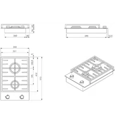
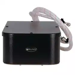
SITE REQUIREMENTS
The Nitron Gas Module dimensions are 8.3"W x 13.8"D x 4.7"H. The NGM should be placed in a upright
position on a solid surface nearest or directly underneath the Nitron Cold Draft Dispenser. Environment
must be below 90 Degrees Fahrenheit, such as in a cafe, convenience store, or restaurant and not near
other appliances that may emit gasses, oils, or other fluids. Do Not allow vents on the sides of the NGM to
get blocked.
CAUTION: To reduce the risk of Electric Shock or Injury, use and store indoors only. Adapter plugs or
extension cords may not be used to facilitate electrical hook-up to the equipment power cord.
APPLICATION: The NGM is not to be used with a Keg style dispense systems. The output pressure of the
NGM will be around 100-112psig.
CAUTION: To reduce the risk of Electric Shock or Injury, use and store indoors only. Adapter plugs or exten-
sion cords may not be used to facilitate electrical hook-up to the equipment power cord.
GROUNDING INSTRUCTIONS
This product must be grounded. In the event of an electrical short circuit, grounding reduces the risk of
electric shock by providing an escape wire for the electric current. This product is equipped with a cord
having a grounding wire with an appropriate grounding plug. The plug must be plugged into an outlet that is
properly installed and grounded in accordance
with all local codes and ordinances.
WARNING: Improper installation of the grounding plug is able to result in a risk of electric shock. When
repair or replacement of the cord or plug is required, do not connect the grounding wire to either flat blade
terminal. The wire with insulation having an outer surface that is green with or without yellow stripes is
the grounding wire. Contact a qualified electrician or serviceman when the grounding instructions are not
completely understood, or when in doubt as to whether the product is properly grounded. Do not modify the
plug provided; if it does not fit the outlet, have the proper outlet installed by a qualified electrician.
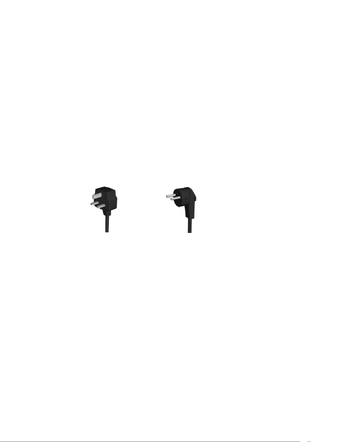
Euro Plug
UK Plug
220-240 Volt
UK Plug
220-240 Volt
Euro Plug
Euro Plug
UK Plug
ELECTRICAL REQUIREMENTS
The 220V-240V rated dispensers have an attached cord set with 2-wire, grounded, rated 240VAC, 13 amp
(UK) or 16 amp (Europe), single phase, 50/60Hz.
Refer to the data plate for exact electrical requirements.
121521

7
NGM INSTALL & OPERATION CHECKLIST
Nitron Gas Module Install/Operation Checklist:
□ Environment around Nitron Gas Module must be below 90° Fahrenheit.
□ Nitron Gas Module cannot be near other appliances that may emit gasses, oils, or other fluids.
□ Nitron Gas Module vents on the side must not get blocked by other objects.
□ Nitron Gas Module must be placed in a upright position on a solid surface under the counter or
underneath the Nitron Cold Draft Dispenser.
□ Locate nylon flare seals in parts box and ensure they get installed into female flare fittings
connected to gas tube before gas tube assembly is connected between the Nitron Gas Module
outlet flare fitting and Nitron Cold Draft Dispenser gas inlet flare fitting.
Note: Nylon seal assists in proper sealing between the two metal fittings being connected together.
□ Installing the Nitron Gas Module to a Nitron Cold Draft Dispenser, the Nitron Cold Draft Dispenser
“Red Empty Indicator LED” must be disconnected on the inner door before the door cover is
installed onto the dispenser door.
□ After plugging in the Nitron Gas Module, the module should operate to pressurize the gas line and
shut off within a few minutes (dependent upon length of gas line between Module and Dispenser).
□ After Nitron Cold Draft is set-up and calibrated, the Nitron Gas Module may not run with each drink
dispense. Draw 1-2 Nitro drinks from the dispenser to confirm Gas Module will cycle (On/Off). The
Nitron Gas Module should run 10-30 seconds then shut off.
121521
8
STEP 1: Determine if the Nitron Gas Module (NGM) is going to be installed to an existing installed Nitron
2
Cold Draft dispenser using N
2
gas supply from a cylinder or along side a new dispenser installation.
Existing Nitron
2
Cold Draft Installation - Go to “N
2
Gas Cylinder Removal Instruction” before continuing with
Step 2.
STEP 2: Place the Nitron Gas Module (NGM) near or under the Nitron dispenser. Adjust to extend the feet
of the Nitron dispenser approximately 1.0 inch to accommodate NGM placement underneath the Nitron
dispenser.
NOTE: The Nitron dispenser must be disconnected from the power source until specified in the instruction to
power up dispenser.
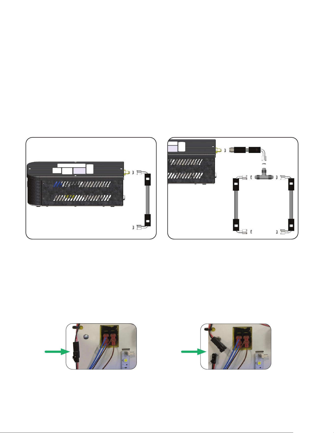
STEP 3: Locate the hose and sealing washers that came with the Nitron Gas Module, install the flare
washers upon connecting the hose from the NGM to the Nitron dispenser flare fitting for proper seal at
the flare connections (Fig.1-1). Use a T-fitting if connecting to a 2nd Nitron dispenser (Fig.1-2).
STEP 7: After completion of disconnecting Nitron dispenser’s red N
2
Empty LED and Nitron Door Cover Instal-
lation, the dispenser can be connected to a power source. The NGM is now ready for use. As the pressure is
depleted by dispensing drinks from the Nitron dispenser, the NGM will automatically cycle to re-pressurize the line.
Fig.2-1
Fig.2-2
DisconnectedConnected
NGM INITIAL SET UP INSTRUCTION
1 Nitron Dispenser
STEP 4
: Plug-in the NGM power cord into a dedicated 220-230Volt, 20Amp rated outlet.
STEP 5: Wait a few seconds for the NGM to pressurize the line between the NGM and Nitron dispenser and
shut off. Check for leaks.
STEP 6: Before installing a door cover or an existing door cover on a Nitron dispenser, disable the red LED
indicator light (for an empty N
2
tank) mounted on the inner door by disconnecting the connectors. Locate
the black and red wire coming from the red LED going to a 2-pin connector junction (Fig.2-1). Disconnect
the 2 pin connector (Fig.2-2). Next, follow the Door Cover Installation instruction outlined in the Nitron
2
Installation & Operating Guide.
Fig.1-2Fig.1-1
2 Nitron Dispensers
NGM
NGM
121521

9
N
2
GAS CYLINDER REMOVAL INSTRUCTION
Warning: A nitrogen gas cylinder is under extremely high vapor pressure which will need to be handled with
care during disconnect from the dispenser. Nitrogen cylinders will have a DOT label identifying the gas and
hazards.
STEP 1: Locate the N
2
supply cylinder and verify it only supplies nitrogen to the BUNN Nitron
2
Cold Draft
dispenser only.
STEP 2: Turn the main cylinder On/Off valve to the Off position.
STEP 3: Place an empty container under the dispenser nozzles. Pull the “Nitro Coffee” tap handle to relieve
the pressure.
STEP 4: Disconnect the nitrogen supply line to the dispenser.
STEP 5: Disconnect the nitrogen pressure regulator from the cylinder.
STEP 6: Inform the location manager or owner that the Nitrogen cylinder is disconnected and should
be properly stored until gas supplier can pick up.
NOTE: During removal, if the cylinder is empty, tag the cylinder as “Empty”.
STEP 7: Disconnect or unplug the Nitron Cold Draft dispenser from the power source.
STEP 8: Proceed onto Step 2 under NGM Initial Set Up Instruction.
121521
10
Recommended Filter Change Frequencies (@ 65 cups/day):
• 1 Nitron Dispenser: 1 Year PM.
• 2 Nitron Dispensers: Every 6 Months.
Value of Preventive Maintenance:
• Reducing unexpected amount of equipment failures throughout a year.
• Extend the equipment life expectancy.
• Reducing the amount of energy consumption.
• Providing the best quality of finished product for the consumer.
• Assures uptime.
• Eliminate premature replacing of equipment.
• Reduce problematic repairs & return service trips.
WARNING - Exercise extreme caution when servicing and
performing preventive maintenance on electrical equipment
and should be performed only by qualified service personnel.
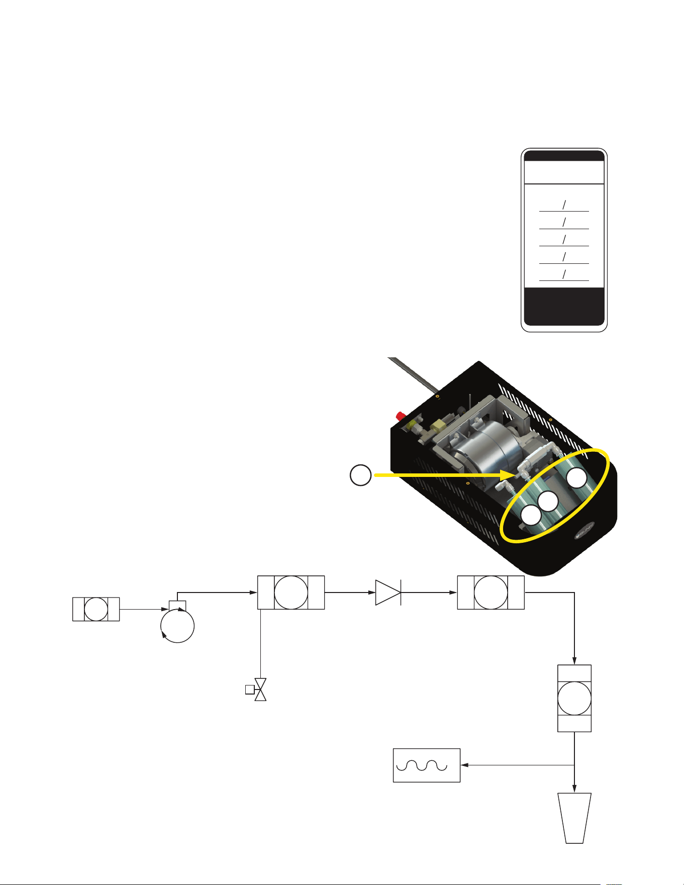
A) Air Intake
B) Water Separation Filter
C) Air Dryer
D) Air Filter
In order to maintain proper operation and long service life, BUNN requires an annual PM if the NGM is
placed in an ideal environment as laid out in the Site Requirements. The PM should take place in conjunction
with the Nitron dispenser’s PM schedule. If the NGM is placed in a less than ideal environment, more
frequent PM’s may be required.
NOTICE: To ensure quality air delivery and optimal performance, change all internal filters per Filter Change
Frequencies Recommendation unless the humidity level is over 50% which may require more frequent filter
changes. Use the included Filter Change sticker to keep track of PM events.
55622.0001
AIR INTAKE
AIR
PUMP
55643.0000
AIR FILTER
OUTLET
BULKHEAD
CONNECTOR
P
PRESSURE
SWITCH
55641.0000
WATER
SEPARATION
FILTER
55642.0000
AIR DRYERCHECK
VALVE
N.O.
DRAIN
VALVE
A
B
AIR FLOW DIAGRAM
INSTALL
MM / YY
/
FILTER CHANGE
55884.0000 B
NOTE:
TO ENSURE QUALITY
AIR DELIVERY TO DISPENSER
CHANGE INTERNAL FILTERS
ANNUALLY.
PREVENTIVE MAINTENANCE
C
D
A
B
D
C
121521

11
WARNING • Exercise extreme caution when servicing electrical equipment.
• Unplug the dispenser when servicing, except when electrical tests are specified.
• Follow recommended service procedures.
• Replace all protective shields or safety notices.
No collar/foam created during a
Nitro Coffee Brew dispense.
Weak or inconsistent collar/foam
on the Nitro Coffee Brew.
1. No power to Nitron Gas Module.
2. Thermal overload tripped in
Nitron Gas Module because of gas
leak in system.
3. Nitron Gas Module start capacitor.
1. Leak in gas line causing con-
tinuous or intermittently Nitron Gas
Module operation.
2. Nitron Gas Module prefilter dirty.
3. Nitron Gas Module desiccant filter
absorption capability depleted.
4. nitron
2
Cold Draft Dispenser:
a) Cleanliness of nitro dispense
nozzle.
b) Stout insert missing in nitro
nozzle.
Check outlet for power and within
acceptable voltage range.
a) Wait for thermal overload to cool
down and reset.
b) Ensure correct environment con-
ditions around Nitron Gas Module.
c) Follow leak testing procedures.
Replace start capacitor.
Rating: 250VAC, 50/60Hz
7.0µF (-5/+10%)
Follow leak testing procedures.
Change all internal filters per Filter
Change Frequencies Recommenda-
tion.
a) Clean Nitro Coffee dispense
nozzle assembly.
b) Install new Stout Insert into the
Nitro Coffee dispense nozzle.
PROBLEM
PROBABLE CAUSE
REMEDY
TROUBLESHOOTING
A troubleshooting guide is provided to suggest probable causes and remedies for the most likely problems
encountered. If the problem remains after exhausting the troubleshooting steps, contact the Bunn-O-Matic
Technical Service Department.
• Inspection, testing, and repair of electrical equipment should be performed only by qualified service personnel.
• All electronic components have 120-240 volt ac and low voltage dc potential on their terminals. Shorting
of terminals or the application of external voltages may result in board failure.
• Intermittent operation of electronic circuit boards is unlikely. Board failure will normally be permanent. If
an intermittent condition is encountered, the cause will likely be a switch contact or a loose connection at
a terminal or crimp.
• Solenoid removal requires interrupting the water supply to the valve. Damage may result if solenoids are
energized for more than ten minutes without a supply of water.
• The use of two wrenches is recommended whenever plumbing fittings are tightened or loosened. This will
help to avoid twists and kinks in the tubing.
• Make certain that all plumbing connections are sealed and electrical connections tight and isolated.
Continued >
121521

12
Excess noise from the Nitron Gas
Module.
Nitron Gas Module won’t start.
Unusual air pump intermittent or
continuous run times resulting in
pump/motor running hot.
1. Hose connection leaking.
2. Improper placement on a unstable
surface.
3. Nitron Gas Module missing or
defective rubber foot.
1. Check main power supply for
power and/or low voltage.
2. Defective start capacitor.
3. Thermal overload tripped in Nitron
Gas Module.
4. Gas leak in the system.
1. A restricted Nitron Gas Module
filter or a gas leak in the sys-
tem.
Inspect entire pressurized line from
Nitron Gas Module to the nitron
2
Cold Draft dispenser.
Ensure proper Nitron Gas Module
placement according to Site require-
ments.
Replace missing or defective rub-
ber foot.
Ensure main power is on and within
120VAC +/-10%.
Replace start capacitor.
Rating: 250VAC, 50/60Hz
7.0µF (-5/+10%)
a) Wait for thermal overload to cool
down and reset.
b) Ensure correct environment con-
ditions around Nitron Gas Module.
c) Follow leak testing procedures.
Change all internal filters per Filter
Change Frequencies Recommenda-
tion.
Follow leak testing procedures.
PROBLEM
PROBABLE CAUSE
REMEDY
TROUBLESHOOTING
121521
13
TROUBLESHOOTING A NITROGEN GAS LEAK
BASIC NITROGEN GAS MODULE OPERATION: The normal operation of a Nitrogen Gas Module installed to a
nitron dispenser pressurizes the Gas Module outlet gas line and the gas line inside the nitron dispenser fairly
quickly. When the pressure switch inside the Gas Module is satisfied, the Gas Module will shut off. When a
Nitro drink is dispensed from the dispenser, the pressure drops below the pressure switch threshold which
will cause the Gas Module to operate again until pressure switch is satisfied.
HINT: The Nitron Gas Module (NGM) may not run with each drink dispense. Draw 1-2 Nitro drinks from the
dispenser to confirm NGM will cycle. The NGM should run 10-30 seconds then shut off.
The NGM may cycle for a few seconds every couple hours. But should not be running continuous. If it runs
continuous, check the system for leaks.
CAUTION: When the Gas Module does not operate at all, distinct humming sound, operates continuously or
intermittently without dispensing a nitro drink from the nitron dispenser, you must look for a gas leak in the
Nitrogen Gas Module, NGM Supply Tube Assembly, Nitron Dispenser Internal Gas Tubes, Fittings and
Connection Points.
LEAK DETECTION: Use a basic soap solution or equivalent product to test and confirm gas leakage in the
Nitrogen Gas Module, Nitron Dispenser gas line and all the associated gas line fittings and connection points
which are held under pressure. A soap solution is sprayed or brushed over the areas of probable leakage. A
leak is confirmed by bubbles in the soap film. Once leak has been located, wipe soap solution from test site
and repair site. After repair, re-test the site with soap solution and ensure leak has been repaired.
LEAK TESTING CRITERIA: The testing criteria for a Nitrogen System Gas Leak is outlined in 3 troubleshooting
categories that are in logical order.
INSTRUCTION FOR TROUBLESHOOTING NGM
SUPPLY TUBE ASSEMBLY
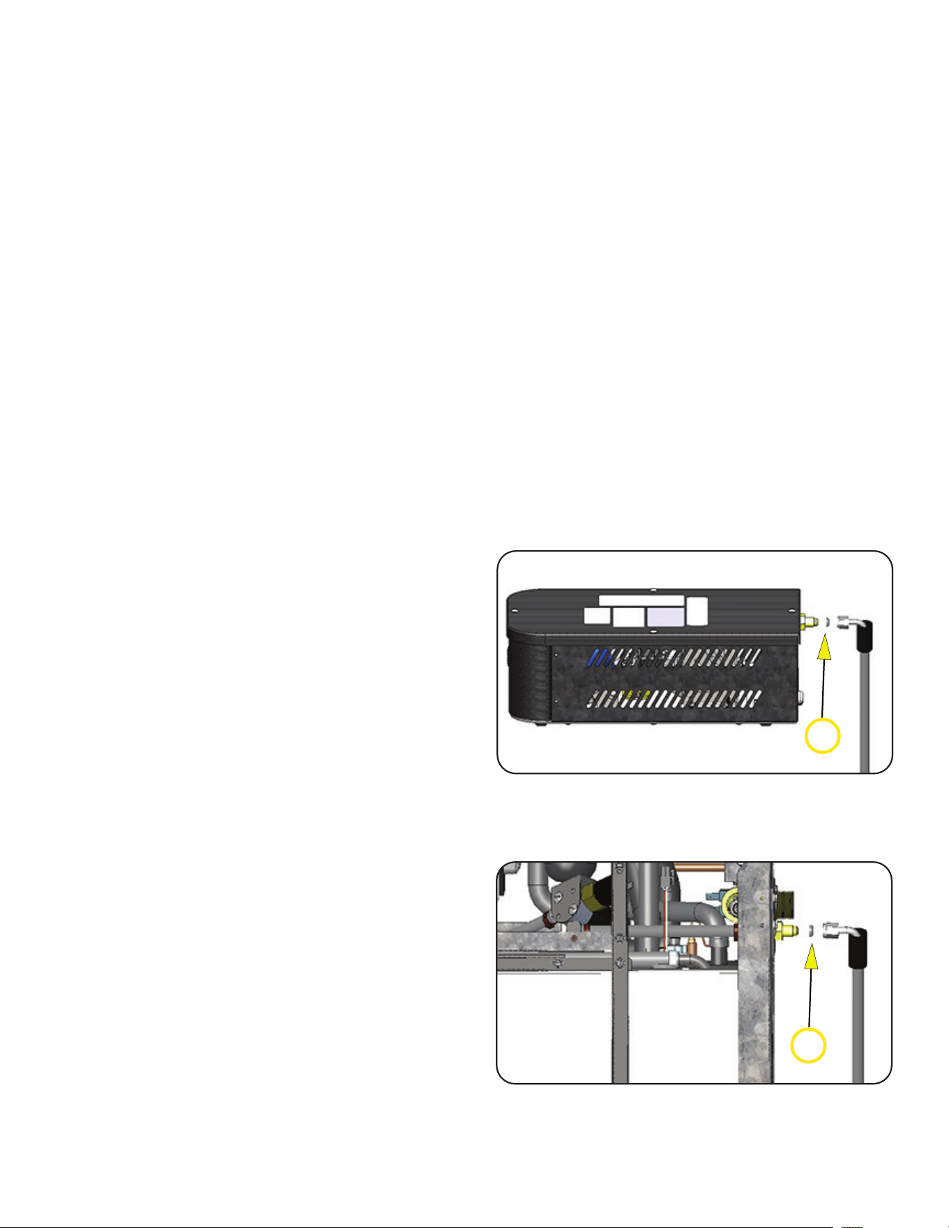
Test Procedure 1:
1. Locate NGM machine supplying nitrogen to
dispenser.
Note: Ensure NGM is operating by dispensing a
nitro drink from the dispenser.
2. Apply soap solution around the tube assembly
connected to the NGM outlet gas fitting. (Fig. 3-1)
3. Apply soap solution around tube assembly
connected to the Nitron Dispenser inlet gas fitting.
(Fig. 3-2)
4. If leak site confirmed by bubbles around tubing
connection points, disconnect NGM from power.
5. Disconnect the gas tube assembly from NGM and
nitron dispenser.
6. If the nylon flare seal is not present or defective
from being over tightened, insert new flare
seal in each female flare fitting.
7. Re-connect gas tube assembly to NGM and Nitron
dispenser.
8. Re- connect power to NGM. Apply soap solution
again to connection points and confirm leak has
been repaired. When completed, wipe off soap film.
9. The NGM will turn on and pressurize to
pressure limit and shut off. If NGM continues
running, go to Troubleshooting NGM System Leak.
FIG. 3 -1 NGM Gas Outlet and Tube
Assembly
6
FIG. 3-2 Nitron Dispenser Gas Inlet
Connection
6
121521
14
INSTRUCTION FOR TROUBLESHOOTING NGM
SYSTEM LEAK
Test Procedure 2:
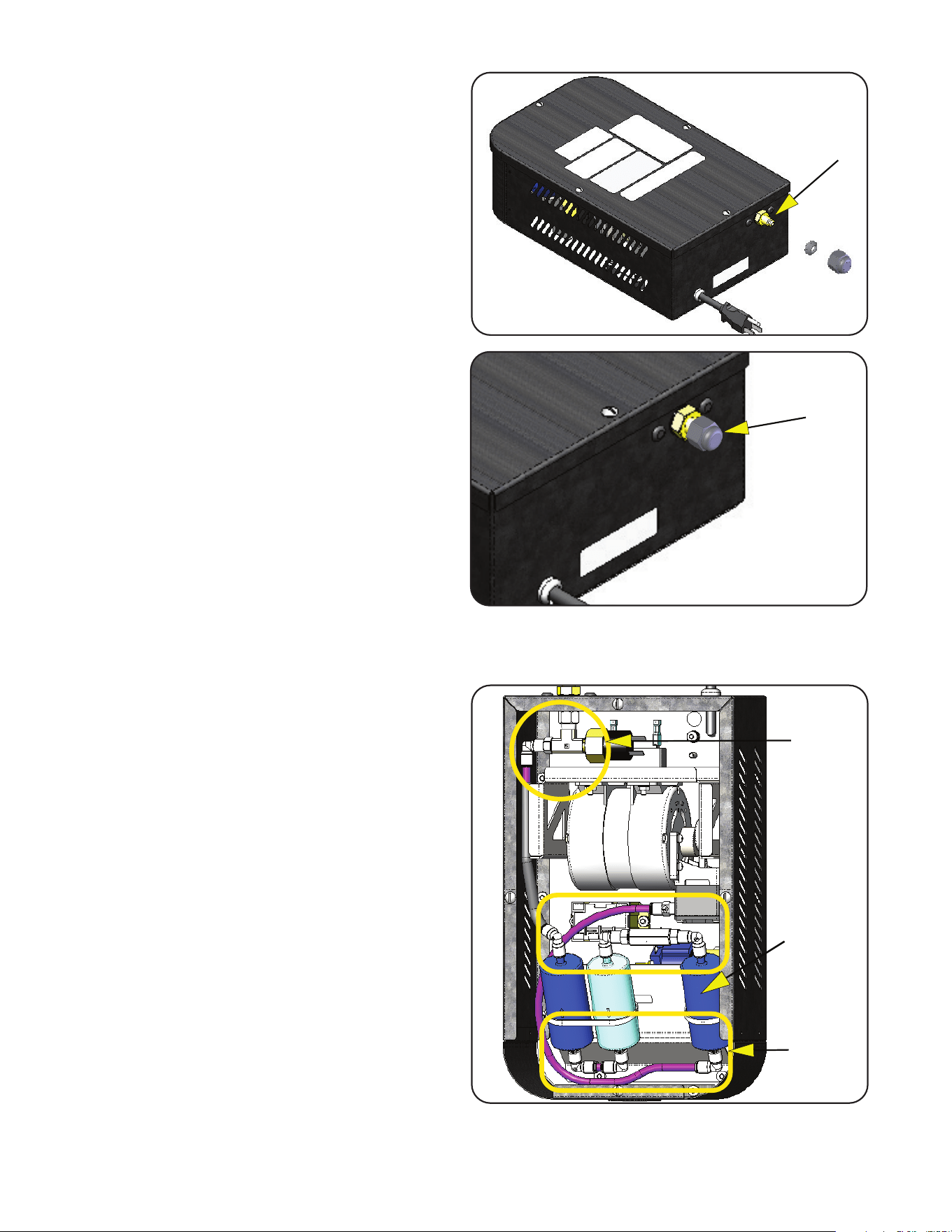
1. Disconnect power from NGM.
2. Disconnect gas tube assembly from NGM outlet
fitting.
Note: Is nylon seal present after disconnecting
tube assembly from NGM fitting?
No -Nylon seal must be installed between this
connection point.
3. Install a flare cap with nylon seal onto the NGM
outlet gas fitting and tighten.
4. Re-connect power to NGM.
5. The NGM will turn on and pressurize to pressure
limit and shut off.
6. Wait approximately 3 minutes to ensure the NGM
remains off and does not cycle (on/off).
NGM Remained Off During 3 Minute Test - No
need to remove NGM service panels. Go to Nitron
Dispenser and check for leaks.
NGM cycled or Continues to Run During 3
Minute Test - Remove NGM service panel
and apply basic soap solution around all filter
push-in connect fittings on all three filters and entire
housing of first stage filter (Filter B, page 9).
7. If leak site confirmed around a push -in connect
fitting by bubbles in the soap film. Inspect tube
going into fitting and ensure the tube end is cut even
and straight. Burred Edge or Uneven Cut -Replace
tube and fitting.
8. Leak site confirmed around First Stage Filter
Housing. Change all internal filters per Filter
Change Frequencies Recommendation (Pg. 9).
9. Use the included Filter Change sticker to keep
track of Filter Change events.
TROUBLESHOOTING A NITROGEN GAS LEAK
FIG. 4-1 NGM with Flare Seal & Cap
Installed
FIG. 4-2 NGM Filter Connections & First
Stage Filter
First Stage
Filter
Filter
Connections
Filter
Connections
121521
15
INSTRUCTION FOR TROUBLESHOOTING NITRON
DISPENSER SYSTEM LEAK
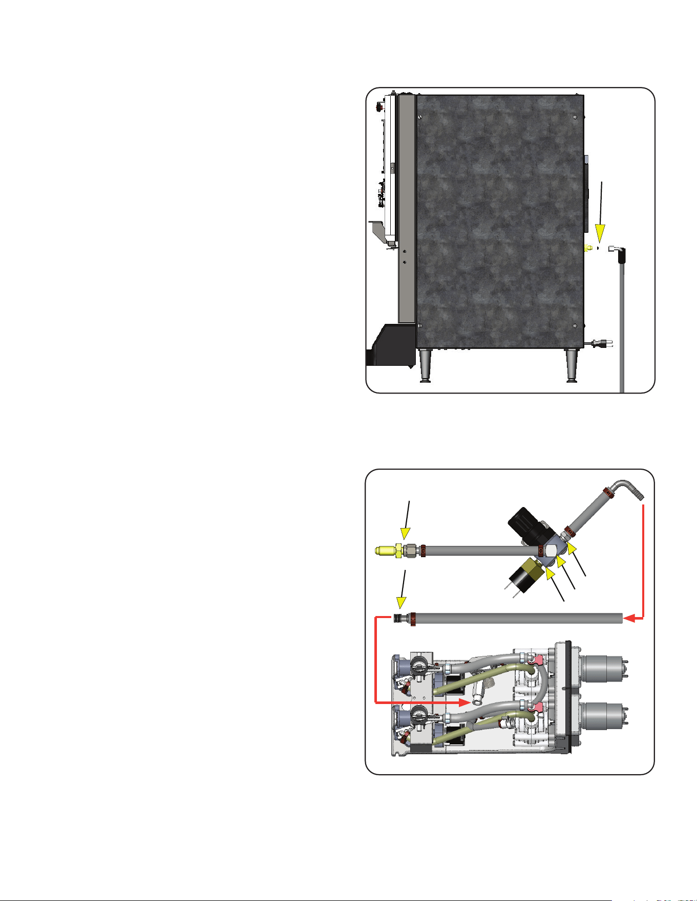
Test Procedure 3:
1. Disconnect power from NGM.
2. Dispense a Nitro drink from dispenser to relieve gas
pressure.
3. Disconnect power to Nitron Dispenser.
4. Disconnect gas tube assembly from Nitron
Dispenser inlet gas fitting. (Fig. 5-1)
Note: Is nylon seal present after disconnecting
tube assembly from dispenser fitting?
No -Nylon flare seal must be installed between this
connection point. (Fig. 5-1)
5. Re-connect gas hose assembly with nylon flare
seal to bulkhead fitting on dispenser and tighten.
(Fig. 5-1)
6. Remove right side panel from Nitron Dispenser.
7. Re-connect power to Nitron Dispenser.
8. Re-connect power to NGM.
9. The NGM will turn on to pressurize the gas
line which may continue to run or cycle
intermittently if a leak exists in Nitron Dispenser.
10. Apply soap solution around the following
connection points. See Fig. 5-2; for connection
points to test.
11. If leak site or sites are confirmed, disconnect power
to NGM and Nitron Dispenser.
12. Make the necessary repair(s).
13. Repeat step 7 thru 10 to confirm leaks have been
repaired.
14. Disconnect power from Nitron Dispenser, wipe soap
film from all check points and re-install side panel.
15. Re-connect Nitron Dispenser power.
16. Dispense a 16 ounce Nitro drink and ensure the
NGM will cycle and turn Off.
TROUBLESHOOTING A NITROGEN GAS LEAK
FIG. 5-1 Nitron Dispenser Gas Inlet Fitting
FIG. 5-2 Gas Line Path Inside Nitron
Dispenser
Flare Seal
Connection Points
121521
16
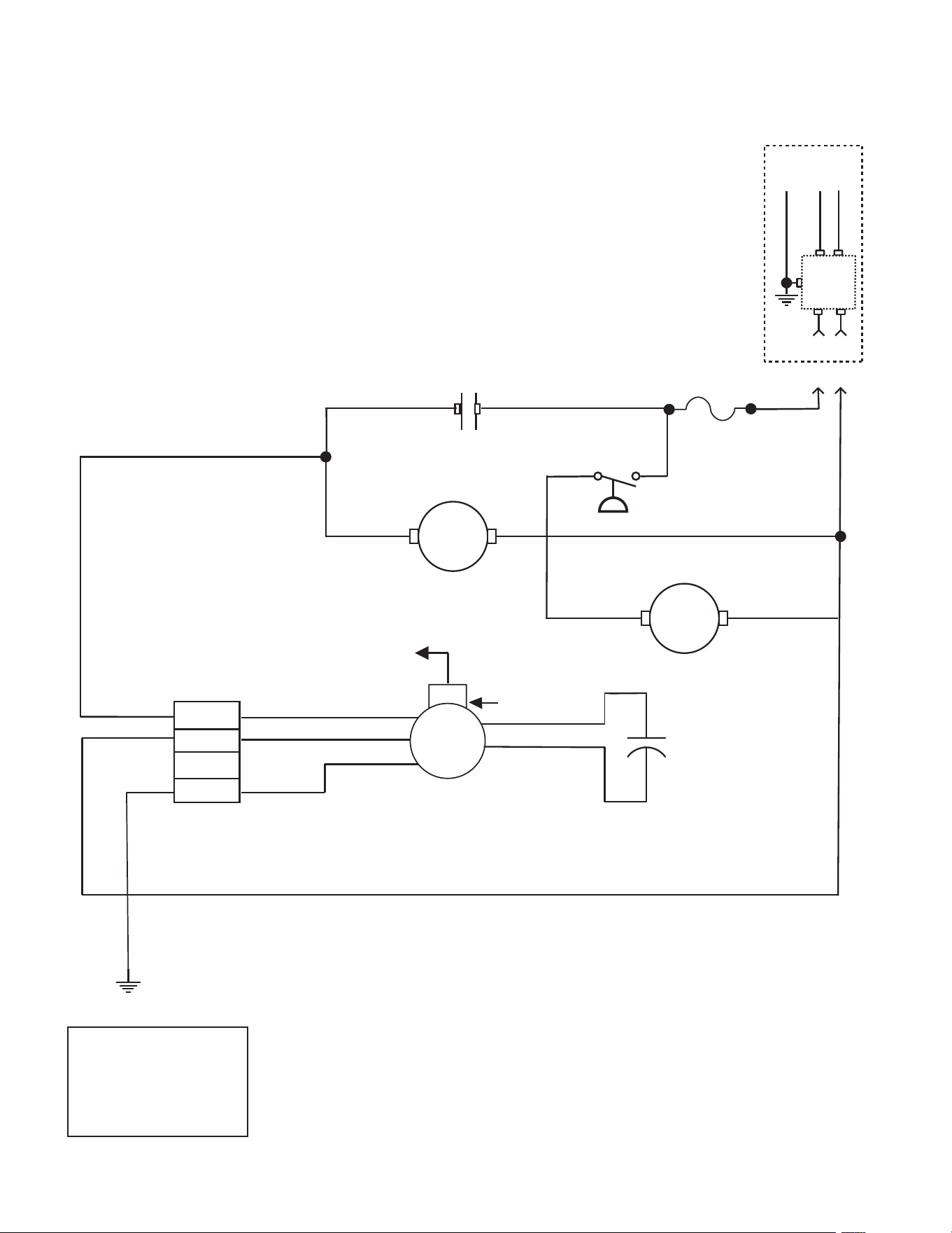
05/20 © 2018 BUNN-O-MATIC CORPORATION
SCHEMATIC WIRING DIAGRAM NITRON GAS MODULE
220-240 VOLTS AC
2 WIRE
SINGLE PHASE
50-60Hz
WHI
BLK
A B
SOLENOID
VALVE
SOL
BLU
BLU
AIR
PUMP
PRESSURE
SWITCH
MOTOR START
CAPACITOR
WHI
WHI
WHI
BLK
BLK
BLK
GRN
GRN
4 PIN
CONNECTOR
1
4
FUSE
WHI
BLK
BLK
K1
K1
A B
220-230V
MODELS
GRN/YEL
NL1GND
BRN
BLU
EMI
FILTER
SCHEMATIC WIRING DIAGRAM OF NITRON GAS MODULE
220-240 VOLT MODELS
121521