EN
CG11UMEN-004
www.bora.com
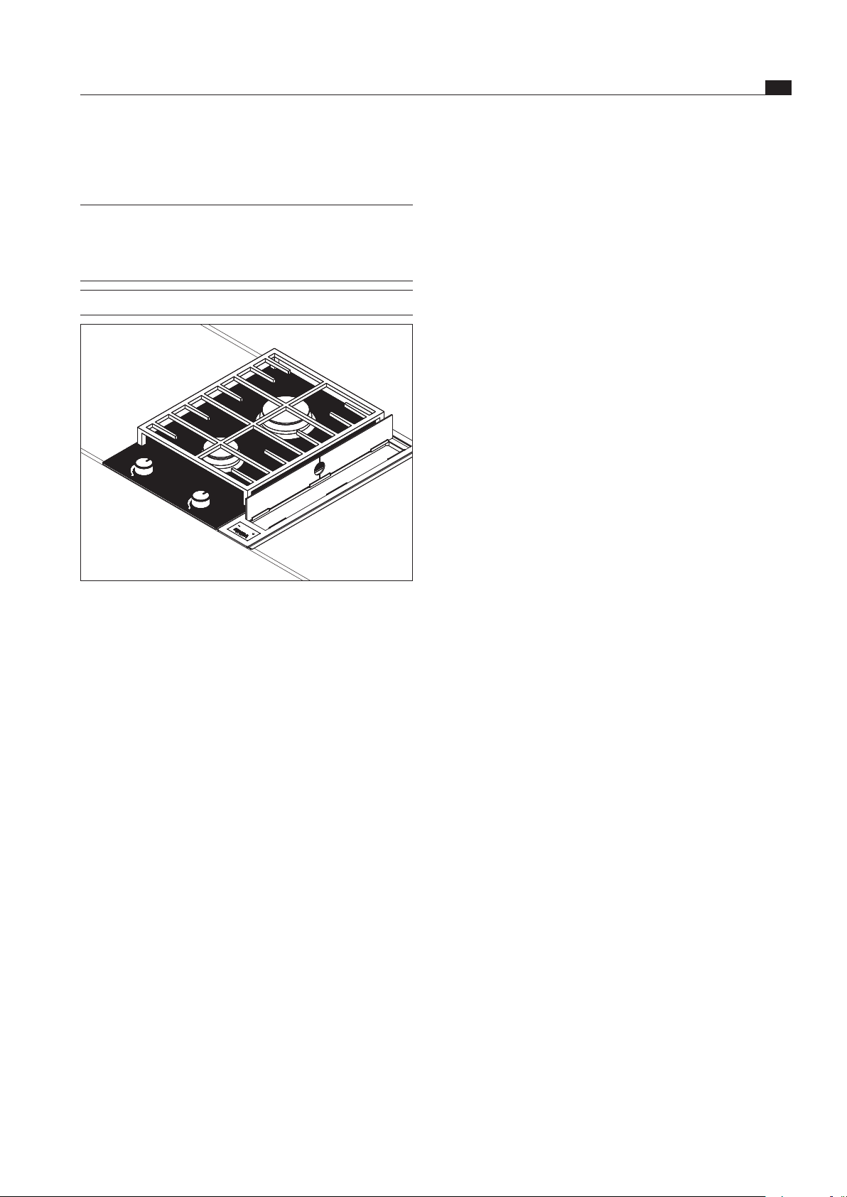
Operating and installation instructions CG11
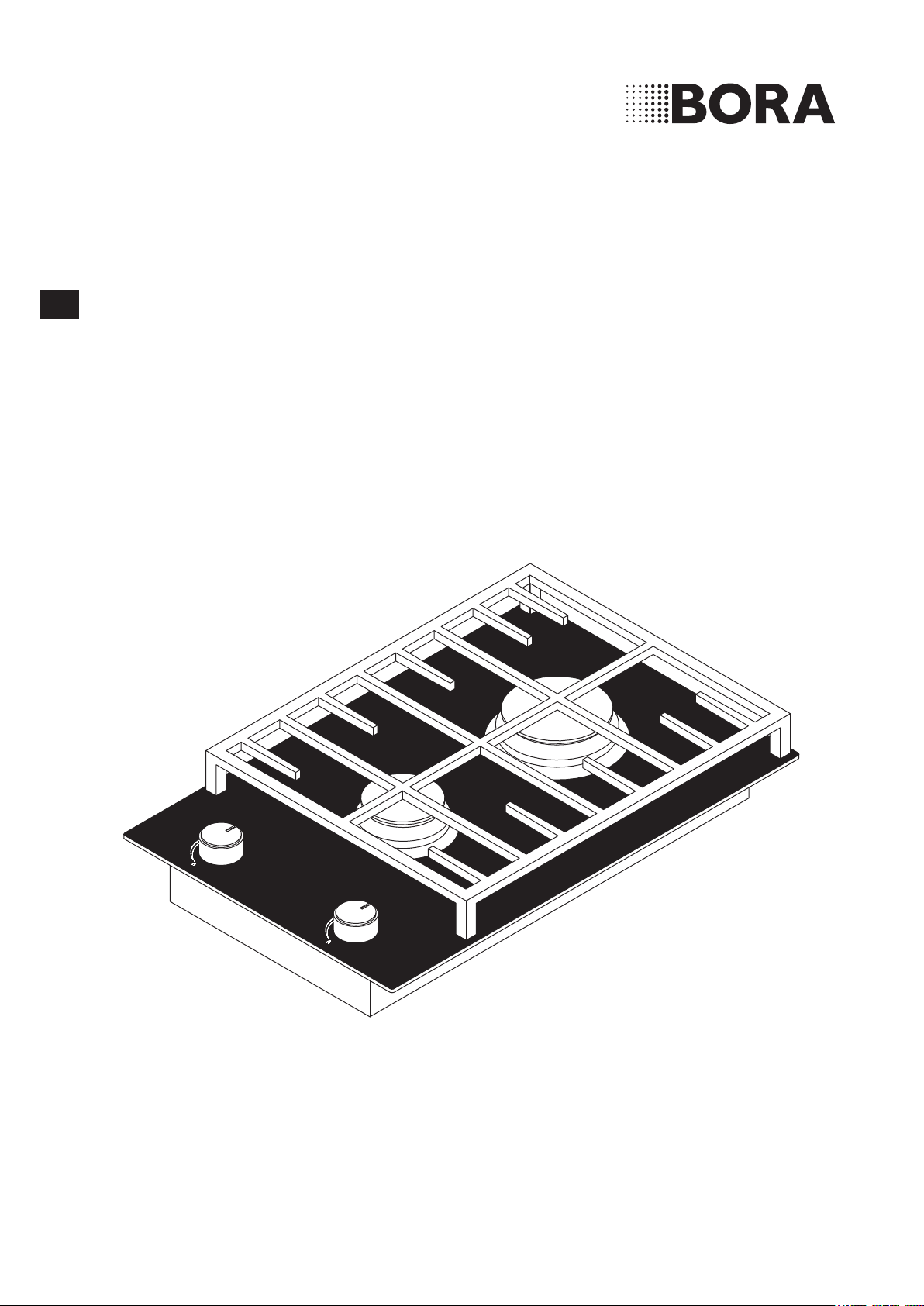
BORA Classic gas-glass-ceramic-cooktop with
2 cooking zones
VB2VRAM0G0NNGQ2

Operating and installation instructions: Original Translation
Manufacturer
BORA Vertriebs GmbH & Co KG
Innstraße 1
6342 Niederndorf
Austria
Contact
T +43 (0) 5373 / 62250-0
www.bora.com
The distribution and duplication of this document, as well as the use and disclosure of its contents are prohibited
unless expressly authorised.
These operating and installation instructions have been drawn up with the greatest of care. But it cannot be ruled
out that subsequent technical modifications have not yet been incorporated or the relevant content has not yet been
adapted. Please accept our apologies in this eventuality. An updated version can be requested from the BORA Service
Team. Subject to printing errors and mistakes.
© BORA Vertriebs GmbH & Co KG
All rights reserved.

EN
3
www.bora.com
Table of Contents
1 General information 4
1.1 Target group ................................................................ 4
1.2
Validity of the operating and installation instructions ...
4
1.3 Other applicable documents ......................................4
1.4 Presentation of information ........................................5
2 Safety 6
2.1 General safety instructions ......................................... 6
2.2 Safety instructions – operation ..................................7
2.3 Safety Instructions – Installation ................................9
2.4 Safety instructions – disassembly and disposal ......10
2.5 Safety instructions – spare parts .............................10
2.6 Use as intended ........................................................10
3 Technical data 11
4 Device description 12
4.1 Structure ...................................................................12
4.2 Operating panel and operating principle ..................12
4.3 Functional principle ...................................................12
4.3.1 Suitable cookware ....................................................12
4.3.2 Power levels ..............................................................13
4.4 Safety devices ...........................................................13
4.4.1 Safety thermocouple.................................................13
5 Installation 14
5.1 Checking the scope of delivery ................................14
5.2 Tool and aids .............................................................14
5.3 Assembly instructions ...............................................14
5.3.1 Safety clearances ......................................................14
5.3.2 Work surface and kitchen units ................................14
5.3.3 Cooktop air intake ....................................................15
5.4 Cut-out dimensions ...................................................15
5.5 Installing the cooktop ...............................................16
5.6 Power connection .....................................................17
5.7 Handover to user ......................................................18
6 Gas installation 19
6.1 Ventilation .................................................................19
6.2 Gas connection .........................................................19
6.2.1 Additional installation notes for Australia and
New Zealand (AUS/NZS) ..........................................20
6.2.2 Gas connection AUS/NZS ........................................20
6.3 Leak test of the gas connection ...............................21
6.4 Changing the gas type ..............................................21
6.4.1 Setting up gas taps ...................................................22
6.5 Handover to user ......................................................23
6.6 Nozzle table ...............................................................23
7 Operation 24
7.1 Ignite the gas burner .................................................24
7.2 Adjusting the power level .........................................24
7.3 Correct use of the gas hob .......................................24
7.4 Using the gas cooktop with a BORA
cooktop extractor .....................................................25
8 Cleaning and Maintenance 26
8.1 Cleaning agents ........................................................26
8.2 Maintaining the cooktop ...........................................26
8.3 Cleaning the cooktop ................................................26
8.3.1 Cleaning of the gas burners .....................................27
8.3.2 Cleaning the control knobs.......................................27
9 Troubleshooting 28
10 Decommissioning, disassembly and
disposal 29
10.1 Decommissioning......................................................29
10.2 Disassembly ..............................................................29
10.3 Environmentally-friendly disposal .............................29
11
Warranty, technical service, spare parts
30
11.1 BORA manufacturer’s warranty ................................30
11.2 Service .......................................................................30
11.3 Spare parts ................................................................30
EN
4
General information
www.bora.com
1 General information
1.1 Target group
These operating and installation instructions apply for the
following target groups:
Target group Requirements
User The appliance can be used by children
aged 8 and above as well as people with
reduced physical, sensory or mental
capacities or a lack of experience and/or
knowledge if they are supervised or have
been instructed how to safely use the
appliance and understand the resultant
risks. Children must be supervised. All
safety and warning information and the
handling instructions in the installation
instructions must be complied with.
Ambitious DIYers Ambitious DIYers can independently
conduct all joinery and installation work
providing they possess the necessary
skills and expertise. They must never
independently establish electricity and
gas connections.
Installation specialists Installation specialists are authorised
to conduct all joinery and installation
work in line with
existing regulations. The
electricity and gas connections must be
certified by a certified engineer for the
applicable trade prior to commissioning.
Electricians The electrical connection may only be
established by a certified engineer.
He/she also assumes responsibility for
the proper electrical installation and
commissioning.
Gas specialists The gas connection may only be
established by certified engineers.
They also assume responsibility for
proper installation and commissioning of
the gas system.
Tab. 1.1 Target groups
INFO BORA Holding GmbH, BORA Vertriebs GmbH
& Co KG, BORA APAC Pty Ltd and BORA
Lüftungstechnik GmbH - hereinafter referred to
as BORA - do not assume any liability for damage
arising from non-adherence to these documents
and from improper assembly! The electricity and
gas connections must be made by a qualified
specialist. Installation must comply with the
valid standards, regulations and laws. All safety
and warning information and the operating and
installation instructions must be complied with.
1.2 Validity of the operating and
installation instructions
These instructions apply to several device versions. It is
therefore possible that some of the features described do
not apply to your appliance.
1.3 Other applicable documents
These operating and installation instructions are valid
in conjunction with other documents, which must be
adhered to.
Please be sure to adhere to all documents that form part
of the scope of delivery.
INFO BORA accepts no liability for damage caused by
failure to comply with these documents!
Directives
This device meets the following EU/EC directives:
2014/30/EU EMC Directive
2014/35/EU Low Voltage Directive
2009/125/EC Ecodesign Directive
2011/65/EU RoHS Directive
2012/19/EU WEEE Directive
Regulations
This device meets the following EU regulations:
(EU) 2016/426 Gas Appliance Regulation
EN
5
General information
www.bora.com
1.4 Presentation of information
To make working with these instructions quick and
easy, consistent formatting, numbering, symbols,
safety instructions, terms and abbreviations are used
throughout.
Handling instructions are market with an arrow.
Always carry out handling instructions in the sequence
shown.
Bullet points are indicated by a square bullet point at
the edge of the line.
Bullet point 1
Bullet point 2
INFO Information points out specific points you must
always comply with.
Safety and warning information
The safety and warning information in these instructions
are highlighted with symbols and signal words.
Safety and warning information is structured as follows:
WARNING SYMBOL AND SIGNAL
WORD!
Type and source of the danger
Consequences of non-compliance
Measures to minimise risk
The following applies:
The warning symbol draws attention to the danger.
The signal word indicates the severity of the risk.
Warning sign Signal word Hazard
Danger Indicates an imminent hazardous
situation which could lead to
death or serious injury
if ignored.
Warning Indicates an imminent hazardous
situation which could lead to
death or serious injury if
ignored.
Caution Indicates a potentially hazardous
situation which could lead to slight
or minor injuries if ignored.
— Caution Indicates a situation which could
result in material damage if
ignored.
Tab. 1.2 Meaning of warning symbols and signal words
EN
6
Safety
www.bora.com
2 Safety
2.1 General safety instructions
INFO The appliance complies with the
stipulated safety requirements. The
user is responsible for appliance
cleaning and maintenance as well as
its safe use. Improper use can lead
to personal injury and damage to
property.
The operating and installation instructions
contain important information about
installation and operation. These enable you
to protect yourself against injuries and
prevent damage to the appliance. Contact
details for further information as well as
application and usage questions can be found
on the back of these operating and
installation instructions.
The term “appliance” is used to refer to
cooktops, cooktop extractors or cooktops
with integrated cooktop extractor.
Read the operating and installation
instructions fully before using the appliance
for the first time.
Always store the operating and installation
instructions within easy reach so that they
can be accessed if required.
Pass the operating and installation
instructions to the next owner if you sell the
appliance.
Conduct all work extremely attentively and
conscientiously.
Check the appliance for visible damage when
unpacking it.
Do not connect a damaged appliance.
Only use the connection cables supplied in
the scope of delivery.
Do not use the appliance until installation is
complete. This is the only way to ensure safe
operation.
Make sure contact with hot cooking surfaces
is not possible.
Do not place any objects on the operating
panel or the cooktop extractor air inlet nozzle.
Avoid over-cooking.
Switch off the appliance after use.
Keep pets away from the appliance.
Do not use the appliance to heat the room.
CAUTION!
Appliance components can cause
injury if dropped!
Appliance components such as pan
supports, operating controls, covers,
grease lters, etc. can cause injury if
dropped.
Place any appliance components
that have been removed in a safe
place near the appliances.
Ensure that no components removed
from the appliance can fall on the
floor.
Recirculation mode
INFO When cooking, additional moisture is
released into the ambient air.
INFO In recirculation mode, only a slight
amount of moisture is removed from
the cooking vapour.
When using recirculation mode, ensure a
sufficient supply of fresh air, e.g. by opening a
window.
Ensure a normal and comfortable room
climate (humidity of 45–60%), e.g. by opening
natural ventilation openings or using domestic
ventilation systems.
After every use in recirculation mode, switch
the cooktop extractor to a low level for about
20 minutes or activate the automatic after-run
function.
Households with children and people with
special needs
The appliance can be used by children aged 8
and above as well as people with reduced
physical, sensory or mental capacities or a
lack of experience and/or knowledge if they
are supervised or have been instructed how
to use the appliance safely and understand
the resultant risks.
Supervise children in the vicinity of the
appliance.
Children must not play with the appliance.
Use the childproofing feature in order to
prevent children from switching on the
cooktop or changing the settings when they
are unattended.
EN
7
Safety
www.bora.com
2.2 Safety instructions – operation
Cooktop
DANGER!
Danger of fire caused by leaving the
cooktop unattended!
Oil or fat in the pot can quickly heat up
and ignite.
Never leave oil or fat to heat up
unattended.
Never extinguish oil and fat fires
with water.
Suffocate the fire, for example by
using a lid.
DANGER!
Risk of explosion caused by
flammable liquids!
Flammable liquids in the vicinity of the
cooktop can explode and cause serious
injury.
Do not spray aerosols in the vicinity
of this appliance while it is in
operation.
Do not place any flammable liquids
in the vicinity of the cooktop.
DANGER!
Risk of electric shock!
Cracks, ssures or fractures in the
glass ceramic panel can damage the
underlying electronics. This can cause
an electrical shock.
If there are any cracks, fissures or
fractures in the glass ceramic,
switch the appliance off
immediately.
Securely disconnect the appliance
from the mains using the LS switch,
fuses, automatic circuit breakers or
contactor.
DANGER!
Risk of explosion from gas!
Gas leaks can cause explosions and
serious injuries.
Keep ignition sources (naked flames,
heaters) away.
Close the gas supply and turn off the
mains supply.
Do not store any items that could be of
interest to children in storage spaces above
or behind the appliance. Otherwise, they will
be tempted to climb onto the appliance.
Keep children and other persons away from
the cooking surfaces when hot.
Unauthorised modifications
Unauthorised modifications can cause the
appliance to pose risks.
Do not make any changes to the appliance.
Cleaning and Maintenance
The appliance must be cleaned at regular
intervals. Dirt can lead to damage or bothersome
odours. Remove dirt immediately.
Any work involving cleaning and maintenance
must not be carried out by children unless
they are supervised at all times while doing
so.
Do not use a steam cleaner for cleaning.
Steam can cause a short circuit on live parts
and thus lead to property damage (see the
Cleaning and Maintenance chapter).
Do not place any hot cookware in the area of
the cooktop display so as not to damage the
underlying electronics.
Do not place any hot cookware in the area of
the operating panel so as not to damage the
underlying electronics.
When cleaning, ensure that no water
penetrates the appliance. Use only a slightly
damp cloth. Never spray the device with
water. Water penetration can cause damage!
Whenever possible, clean the cooktop after
every use.
Clean the cooktop only after it has cooled
down.
When cleaning, only use non-abrasive
detergents to prevent scratching and abrasion
on the surface.
Make sure that the base of the cookware as
well as the cooking zones are clean and dry.
Always lift (do not drag!) the cookware to
prevent scratching and abrasion on the
surface.
EN
8
Safety
www.bora.com
WARNING!
Risk of burns from hot objects!
The cooktop and its exposed parts
are hot when the cooktop is in use
and during the cooling phase. Objects
on the cooktop heat up very quickly
and can cause serious burns. This
particularly applies to metal objects
(e.g. knives, forks, spoons, lids or
cooktop extractor covers).
Do not place any items on the
cooktop.
Please use suitable tools (pot
holders, oven gloves).
WARNING!
Risk of burns from hot cookware!
Handles projecting over the edge are
enticing for children to grab.
Do not turn pot and pan handles so
they stick out beyond the work
surface.
Make sure that children cannot pull
hot pots and pans over.
WARNING!
Risk of burns!
Liquid between the cooking zone and
the pan base can evaporate and cause
burns.
Make sure that the cooking zone
and the pan base are always dry.
CAUTION!
Damage from hard and pointed
objects!
Hard and pointed objects can damage
the glass ceramic panel of the cooktop.
Do not use the surface of the
cooktop as a worktop.
Do not use hard and pointed objects
when working on the cooktop.
CAUTION!
Damage from sugary and salty foods!
Sugary and salty foods and juices can
damage the hot cooking zone.
Make sure sugary and salty foods or
juices do not get onto the cooking
zone while it is hot.
Remove sugary and salty foods and
juices from the hot cooking zone
immediately.
DANGER!
Risk of asphyxiation as a result of a
gas leak!
Gas leaks can cause asphyxiation.
If you smell gas while using the
appliance, switch it off immediately.
Close the gas supply immediately.
Ensure there is a good supply of
fresh air (open doors and windows).
Do not use any light switches or
device switches.
Do not remove plugs from sockets
(risk of sparking).
Do not use electrical devices.
Inform customer services or your
gas installer immediately.
DANGER!
Fire risk from naked flame!
A naked ame can cause adjacent
objects to catch re.
Turn the gas flame down to the
lowest level if you remove pots or
pans briefly from the hob.
Never leave a naked flame
unattended.
Extinguish any fire using a lid or a
fire blanket, for example.
Close the gas supply and turn off the
mains supply.
WARNING!
Risk of burns from hot cooktop!
The cooktop and its exposed areas get
hot during use. Once the cooking zone
is switched o, it takes a little while to
cool down to below 60 °C. Touching
hot surfaces can cause serious burns.
Never touch the cooktop when it is
hot.
Keep children away from the
cooktop when it is hot or ensure
they are supervised at all times.
WARNING!
Risk of fire from objects on the
cooking surfaces!
The cooktop and its exposed parts are
hot when the cooking zone is switched
on and during the cooling phase.
Objects on the cooktop can heat up
and catch re.
Do not place any items on the
cooktop.
EN
9
Safety
www.bora.com
CAUTION!
Escaping hot liquids!
Unattended pans can boil over allowing
hot liquids to escape.
Always keep an eye on pans while
cooking.
Short cooking sessions must be
constantly monitored.
CAUTION!
Damage caused by objects on the
cooktop!
Objects such as cookware lids on the
cooktop can damage the glass ceramic
panel.
Do not place any objects on the
cooktop while it is hot.
2.3 Safety Instructions – Installation
The appliance must only be installed and
assembled by trained specialists who are familiar
with and comply with the standard national
regulations and supplementary regulations of the
local utility companies.
Work on electrical components must be
conducted by trained electrical personnel.
The electrical safety of the appliance is only
guaranteed if it is connected to a protective
conductor system that has been installed in line
with regulations. Ensure that this basic safety
precaution is met.
The gas connection may only be carried out
by an authorised gas fitter in accordance with
applicable legal regulations. Comply with local
regulations of the utility companies.
Cooktop
DANGER!
Risk of electric shock!
Connecting the appliance to the mains
incorrectly poses a risk of electric
shock.
Make sure that the appliance has a
fixed connection to the mains
voltage.
Make sure that the appliance is
connected to a properly installed
protective conductor system.
Make sure that technical equipment
is provided to enable all of the
appliance’s poles to be disconnected
from the mains with a contact
opening width of at least 3 mm (LS
switch and automatic circuit
breakers, fuses, contactor).
DANGER!
Risk of electric shock!
The connection cable can be damaged
if it comes into contact with hot
cooking zones. A damaged connection
cable can cause a (fatal) electrical
shock.
Make sure that the connection cable
does not come into contact with hot
cooking surfaces.
Make sure that the connection cable
does not become trapped or
damaged.
DANGER!
Risk of explosion from gas!
Gas leaks can cause explosions and
serious injuries.
Keep ignition sources (naked flames,
heaters) away.
Close the gas supply and turn off the
mains supply.
Plug any leaks immediately.
CAUTION!
Lifting heavy loads can cause back
injuries!
If not handled correctly, removing and
installing the appliance can cause
injuries to the limbs or torso.
Removing the cooktop from the
packaging is a two-person job.
Placing the cooktop into the worktop
cut-out is a two-person job.
Use appropriate aids to prevent
damage or injuries to limbs or torso.
EN
10
Safety
www.bora.com
Check the appliance for visible damage prior
to installation.
Do not install any damaged appliance.
A damaged appliance may put your safety at
risk.
Repair and maintenance work may only be
carried out by specialists authorised by the
manufacturer.
Special safety information for exhaust systems
Please pay attention to the channel length
between the fan and the wall sleeve in
straight channel design.
A minimum space of 75 cm between the blow
out opening of the fan and the blow out
opening of the wall sleeve must be planned in.
2.4 Safety instructions –
disassembly and disposal
The appliance must only be disassembled by
trained specialists who are familiar with and
comply with the standard national regulations
and supplementary regulations of the local utility
companies.
Work on electrical components must only be
conducted by trained electrical personnel.
Work on the gas connection may only be carried
out by an authorised gas fitter in accordance
with applicable legal regulations. Comply with
the local regulations of the utility companies.
DANGER!
Risk of electric shock!
Incorrectly disconnecting the appliance
from the mains results in a risk of
electric shock.
Securely disconnect the appliance
from the mains using LS switches,
fuses, automatic circuit breakers or
contactors.
Use an authorised measuring device
to ensure that there is no power to
the appliance.
DANGER!
Risk of asphyxiation!
Packaging components (e.g. lm,
polystyrene) can be life-threatening for
children.
Store all packaging components out
of reach of children.
Dispose of the packaging properly
and immediately.
2.5 Safety instructions – spare parts
WARNING!
Risk of injury and damage to
property!
Incorrect components can lead to
personal injury or damage to the
appliance. Modications, additions or
alterations to the appliance can lead to
safety risks.
Only use original spare parts for
repairs.
2.6 Use as intended
The appliance cannot be used at altitudes above
2,000 m (metres above sea level). The appliance
is solely intended for preparing food in private
households. This appliance is not intended for:
Outdoor use
Installation in vehicles
Heating rooms
Use in non-stationary installation sites (e.g. on
ships)
Use with an external timer or a separate
remote control system (remote operation)
Any use other than that specified in these
operating and installation instructions or any use
that goes beyond that which is described here is
classed as unintended. BORA does not assume
any liability for damages caused by improper use
or incorrect operation.
All misuse is prohibited!
INFO BORA Holding GmbH, BORA Vertriebs
GmbH & Co KG, BORA APAC Pty Ltd
and BORA Lüftungstechnik GmbH do
not assume any liability for damage
arising from non-adherence to the
safety and warning information.

EN
11
Technical data
www.bora.com
3 Technical data
Parameter Value
Supply voltage 220 - 240 V
Frequency 50/60 Hz
Power consumption 3.9 kW
Fuse protection, minimum 1 x 0.5 A
Cooktop dimensions
(width x depth x height)
340 x 515 x 60 mm
Pan support dimensions
(width x depth x height)
330 x 410 x 45 mm
Weight (incl. accessories/packaging) 9.7 kg
Cooktop
Power levels Continuous
Front normal burner 450 – 1000 W
Back high-power burner 800 – 2900 W
Total nominal connection values
G20/20 mbar
3.90 kW
0.371 m³/h
Total nominal connection values
G30/50 mbar
3.80 kW
276 g/h
Total nominal connection values
G31/50 mbar
3.80 kW
272 g/h
Cooktop energy consumption G20/20 mbar **
Front high-power burner 2800 – 2900 W 56,6 %
Tab. 3.1 Technical data
** Pursuant to EU Regulation No 66/2014 implementing
Directive 2009/125/EC, the power
(energy consumption) has been checked and
calculated in line with EN 30-2-1 using G20.
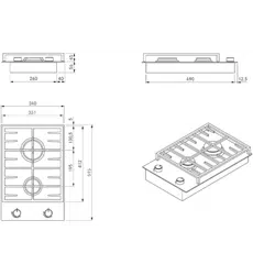
Device dimensions
340
195
515
45
60
Fig. 3.1 Device dimensions
EN
12
Device description
www.bora.com
4 Device description
Observe all safety and warning information during
operation (see the Safety chapter).
The cooktop has the following features:
Front normal burner
Back high-power burner
Two control knobs
Cast iron pan support
4.1 Structure
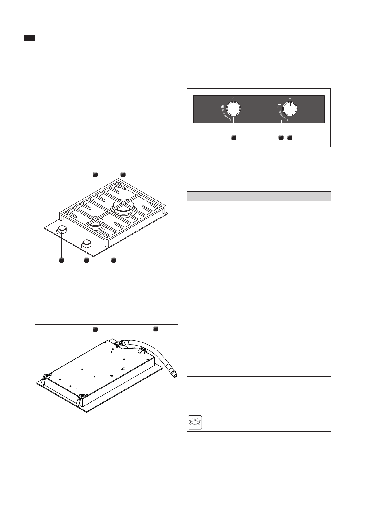
1 2
45 3
Fig. 4.1 Cooktop
[1] Front normal burner
[2] Back high-power burner
[3] Pan support
[4] Control knob for the front hob
[5] Control knob for the back hob
1
2
Fig. 4.1 Underside of the cooktop
[1] Cooktop
[2] Gas connection hose
The gas connection is located in the rear and on the right
hand underside of these appliances: 30 mm.
4.2 Operating panel and operating
principle
3
2
1
Fig. 4.2 Operating panel
[1] Control knob for the back hob
[2] Power display
[3] Control knob for the front hob
Display panel Display Meaning
Power levels Small flame Minimal gas output
Large flame Maximum gas output
0 position No gas output
Tab. 4.1 Signicance of the power levels
Knob operation
The operating panel is equipped with two control knobs.
The control knobs are used to ignite the burner, switch
hobs on and off and regulate the relevant hob. To operate
the appliance, set the control knob to the corresponding
power level.
4.3 Functional principle
If a cooking zone is switched on, the flame generates
heat, which directly heats the bottom of the cookware.
The power levels can be continuously adjusted.
4.3.1 Suitable cookware
INFO The heating and heat through time for the base
of the cookware as well as the cooking results
are significantly influenced by the structure and
material of the cookware.
Cookware with this symbol is suitable for gas
cooktops.
Suitable cookware is made of:
Copper
Stainless steel
Aluminium
cast iron
EN
13
Device description
www.bora.com
Adhere to the cookware dimensions in the table:
Burner position Recommended
pan diameter
Minimum
pan diameter
Normal burner 100-140 mm 100 mm
High-power
burner
200-220 mm 200 mm
Tab. 4.1 Pan diameters
4.3.2 Power levels
The power output of gas cooktops results in food being
quickly heated. A slight adjustment is needed in
comparison to conventional cooking systems when
selecting the power level in order to avoid burning food.
Activity Power level
Keeping cooked meals warm Minimal flame
Browning chopped vegetables,
fried eggs, veal, poultry
Medium flame
Grilling prawns, corn on the cob,
schnitzel, beef, fish or burgers
Large flame
Heating water and searing Maximum flame
Tab. 4.2 Recommendations for power levels
The specifications provided in the table are standard
values.
4.4 Safety devices
4.4.1 Safety thermocouple
The gas burners are equipped with a safety thermocouple.
This thermocouple monitors the burner flame when the
gas supply is active. If the burner flame goes out
unintentionally, the appliance interrupts the gas supply.
The appliance does not automatically ignite the burner.
EN
14
Installation
www.bora.com
5 Installation
Observe all safety and warning information (see the
Safety section).
Follow the enclosed manufacturer’s information.
INFO The device must not be installed above cooling
devices, dishwashers, stoves, ovens, washing
machines or dryers.
INFO The contact surface of the worktops and wall
sealing strips must be made of a heat-resistant
material (up to approx. 100°C).
INFO The surfaces of adjacent components and units
must be able to withstand temperatures of at
least 90°C.
INFO Worktop cut-outs must be moisture-sealed using
suitable means or, where necessary, fitted with a
thermal insulator.
INFO If the induction glass ceramic wok is used, the
groove dimensions must be increased to 7mm for
flush installation!
5.1 Checking the scope of delivery
Name Quantity
Operating and installation instructions 1
Cooktop fixing screws set 1
Sealing tape 1
Cooktop 1
Glass ceramic scraper 1
Height adjustment plate set 1
Mounting straps set for cooktop 1
Glass ceramic cleaning instructions 1
Tab. 5.1 Scope of delivery
Check the scope of delivery for damage and make sure
it is complete (see Tab. 5.1).
If there are any missing or damaged parts, please
notify BORA After Sales Service.
Do not under any circumstances install parts which are
damaged.
Dispose of transport packaging in the proper manner
(see the Decommissioning and Disposal section).
5.2 Tool and aids
The following tools are required for the correct installation
of the cooktop:
Phillips screwdriver Z2
Silicone for sealing cutting surfaces
5.3 Assembly instructions
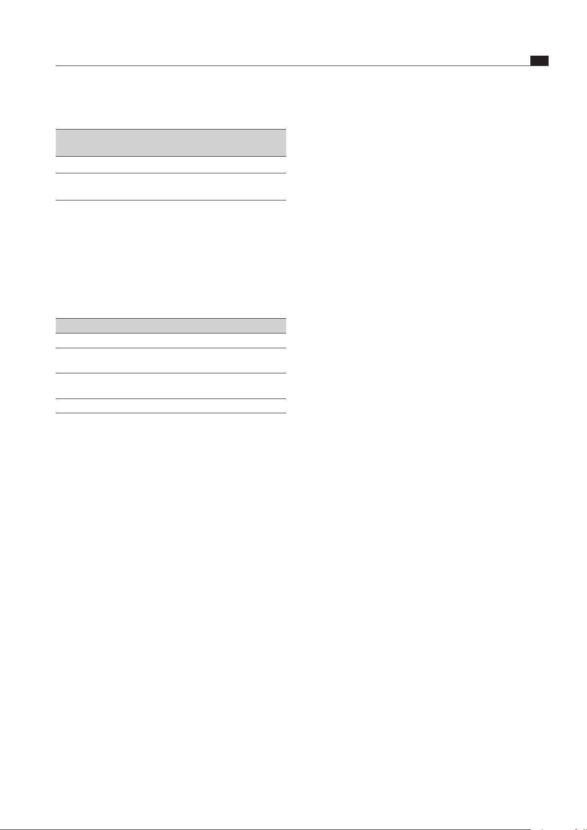
5.3.1 Safety clearances
Maintain the following safety clearances:
1
3
2
Fig. 5.1 Recommended minimum clearances
[1] Rear minimum clearance of 50 mm between the worktop
cut-out and the rear edge of the worktop.
[2] Minimum clearance of 300 mm from the left and right of the
worktop cut-out to the adjacent cabinet or wall.
[3] Minimum clearance of 650 mm between the worktop
and the wall unit. A minimum clearance of 1,000 mm is
recommended for ergonomic reasons.
5.3.2 Work surface and kitchen units
Create the worktop cut-out taking the specified cut-out
dimensions into account.
Make sure that the cutting surfaces of the worktops
are properly sealed.
Observe the instructions provided by the worktop
manufacturer.
Cross bars on the unit in the area of the worktop cut-
out may need to be removed.
Cable protection (false floor) should be mounted
below the appliances. This needs to be removable for
maintenance work.
The drawers and/or shelves in the floor unit must be
removable.
A return flow aperture > 500 cm
2
is required in the
kitchen units for recirculation appliances (e.g. by
shortening the plinth boards or using suitable slatted
plinths).
EN
15
Installation
www.bora.com
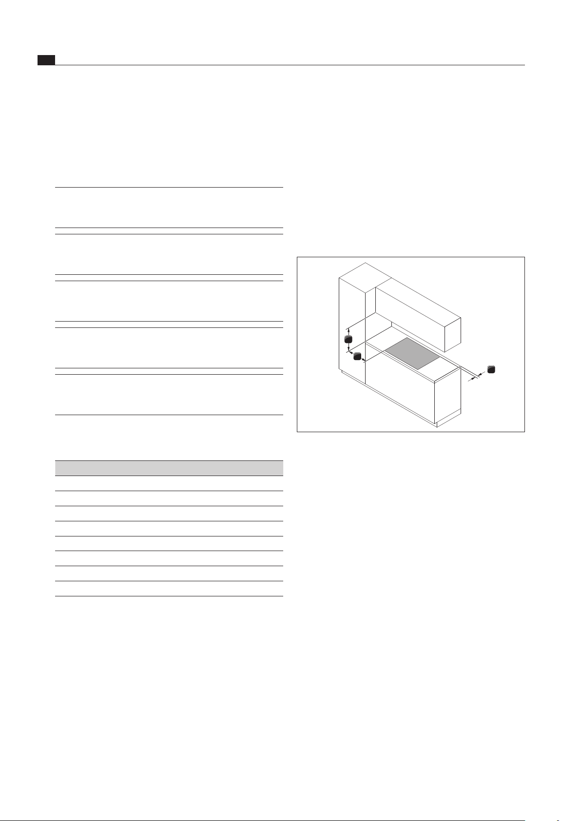
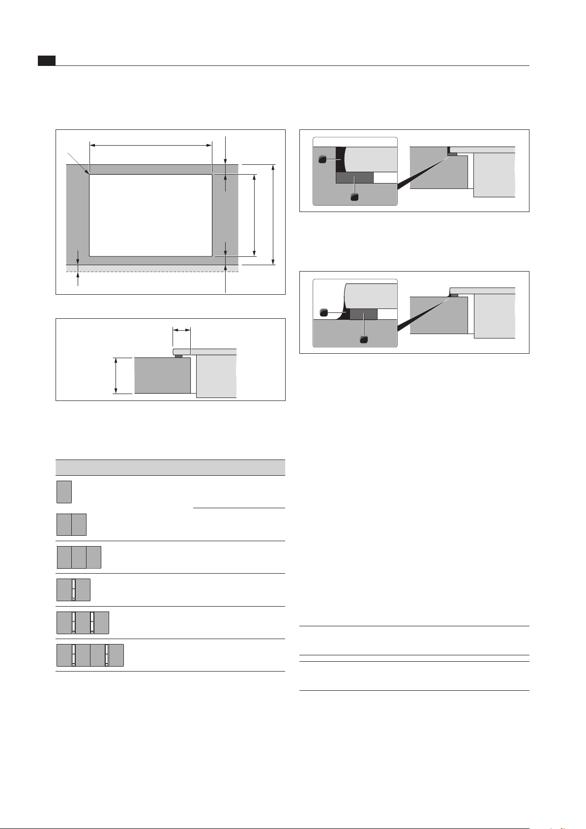
Flush installation
x
(≥ 50)
A ±2
B ±2
519 ±2
≤ R5
≤ R5
≥ 50
495 ±2
≥ 600
Fig. 5.3 Flush installation
5 +0,5
12
10 – 40
Fig. 5.4 Groove dimensions cut-out
Cut-out dimensions when installing cooktops or cooktops
and the BORA cooktop extractor next to each other:
Cooktops/cooktop extractor A in mm B in mm
1/0 344 320
2/0 685 661
3/0 1026 1002
2/1 776 752
3/2 1208 1184
4/2 1549 1525
Tab. 5.2 Cut-out dimensions
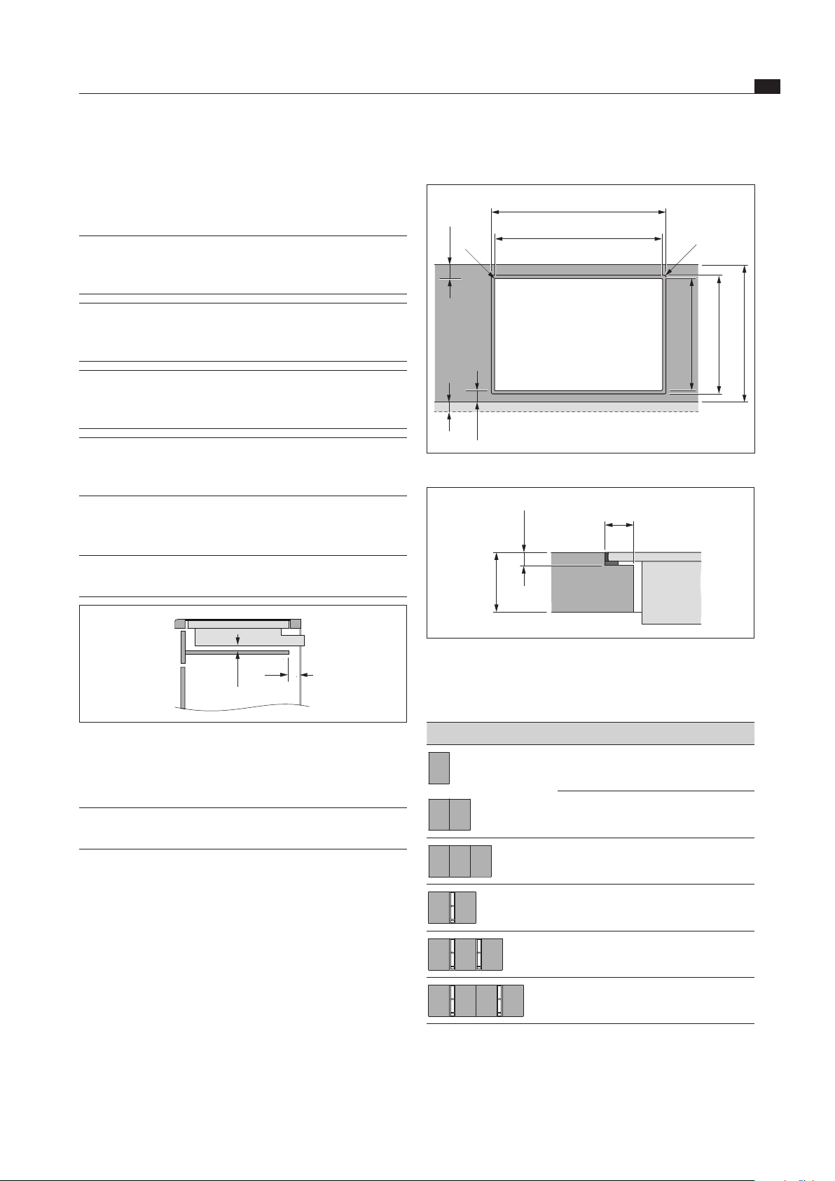
5.3.3 Cooktop air intake
The components in the cooktop which generate heat are
automatically cooled. The warm air is extracted by fans
(cold air flow).
INFO In order to retain the full functionality of the
cooktop in the long term, there must be sufficient
ventilation underneath the cooktop.
INFO The performance of the cooktop is impaired or
the cooktop overheats if the warm air below the
cooktop cannot escape.
INFO If the cooktop overheats, performance is reduced
or the cooktop switches off completely (see
Overheating protection).
INFO For sufficient air intake, an opening cross-
section in the kitchen units of at least 50 cm
2
is
recommended.
Ensure there is sufficient ventilation underneath the
cooktop.
INFO The cable protection (false floor) must not prevent
sufficient ventilation.
> 20
50
Fig. 5.2 Side view of the cable protection and ventilation
5.4 Cut-out dimensions
INFO All dimensions from the front edge of the
front cover.
Please note the worktop overhang x when creating
the worktop cut-out. Applies to flush installation and
surface mounting.
EN
16
Installation
www.bora.com
Attaching the sealing tape
1
2
Fig. 5.7 Sealing tape with ush installation
[1] Black, heat-resistant silicone sealant
[2] Sealing tape
2
1
Fig. 5.8 Sealing tape with surface mounting
[1] Black, heat-resistant silicone sealant
[2] Sealing tape
No sealing tape is required on the side of the appliance
adjacent to the extraction system as the extraction
frame can otherwise be damaged.
With surface mounting, attach the enclosed sealing
tape [2] to the underside of the device before installing
it. Do not leave any gaps with the exception of the side
adjacent to the extraction system.
With flush installation, attach the enclosed sealing tape to
the horizontal cutting edge in the worktop cut-out, even if
you seal the device with a silicone sealant [1] or similar.
Note down the type designation and build number of
the device (FD number) on the back of this manual.
Both details can be found on the nameplate on the
underside of the device.
5.5 Installing the cooktop
INFO Clearance of one millimetre should be planned
between the built-in appliances.
INFO A clearance of two millimetres should be planned
around the built-in appliances.
Surface mounting
x
B ±2
≤ R5
≥ 50
495 ±2
≥ 600
(≥ 50)
Fig. 5.5 Surface mounting
10
10 – 40
Fig. 5.6 Surface mounting cut-out
Cut-out dimensions when installing cooktops or cooktops
and the BORA cooktop extractor next to each other:
Cooktops/cooktop extractor B in mm
1/0 320
2/0 661
3/0 1002
2/1 752
3/2 1184
4/2 1525
Tab. 5.3 Cut-out dimensions

EN
17
Installation
www.bora.com
1
3
2
Fig. 5.11 Mounting brackets
[1] Mounting bracket
[2] Washer
[3] Screw
Affix the cooktop using the mounting brackets [1].
Use the screw [3] and the washer [2] to tighten the
mounting brackets with max. 10 Nm.
Check that the cooktop is positioned correctly.
Once all of the installation work is complete, seal the
devices with black, heat-resistant silicone sealant.
5.6 Power connection
Observe all safety and warning information in the
Safety section.
Observe all national and regional laws and regulations
as well as the supplementary regulations of the local
utility companies.
INFO The power connection may only be established
by a certified specialist. He/she also assumes
responsibility for the proper installation and
commissioning.
The power supply line for use (pre-assembled) must be of
the type H05VV-F or H05VVH2-F as a minimum.
Cross-section: 3G 1.5 mm²
If the connection line has been damaged this must be
replaced by a special connection line. This may only
be done by an authorised member of the After Sales
Service team.
Installing the cooktop
12
Fig. 5.9 Installed cooktop with cooktop extractor
[1] Cooktop
[2] Cooktop extractor
Insert the cooktop [1] next to the cooktop extractor [2]
that has already been installed in the centre.
INFO The cooktop [1] lies on the side rail of the cooktop
extractor [2], which stabilises it.
Precisely position the cooktop [1].
If necessary, use the height adjustment plates to
adjust the cooktop’s installation height.
1
2
Fig. 5.10 Cooktop and height adjustment plates
[1] Cooktop
[2] Height adjustment plates
For surface mounting
Make sure that the sealing tape for the cooktop is flat
against the worktop.
For flush installation
Make sure that the sealing tape of the cooktop is
sealed well all the way round.
EN
18
Installation
www.bora.com
Establishing the power connection
Switch off the main switch/automatic circuit breaker
before connecting the cooktop.
Secure the main switch/automatic circuit breaker
against being switched back on without permission.
Make sure the power to the appliance is disconnected.
Connect the mains cable.
Only connect the cooktop using a permanent
connection to a power supply cable.
1
L1
2
N PE
220 - 240 V~
Fig. 5.12 Connection diagram 1-phase
Check that the cooktop has been correctly installed.
Switch on the main switch/automatic circuit breaker.
Put the cooktop into operation (see the Operation section).
Check that all the functions are working correctly.
5.7 Handover to user
Once installation is complete:
Explain the main functions to the user.
Explain all safety-related aspects of operation and
handling to the user.
Provide the user with the accessories and operating
and installation instructions for safe storage.
EN
19
Gas installation
www.bora.com
6 Gas installation
Observe all safety and warning information (see the
Safety section).
Observe all national and regional laws and regulations,
as well as the supplementary regulations of the local
gas supply companies.
Follow the enclosed manufacturer‘s information.
INFO Taking into account the applicable valid
regulations, the cooktop must be connected
to the gas line with an upstream stopcock.
INFO The gas supply pipe can be connected after
the gas cooktop has been installed.
INFO The hose connection must be laid in such a way
that it is not subject to deformation, buckling or
abrasion.
INFO The stopcock and gas supply pipe connections
must be accessible.
INFO It must be possible to inspect the entire length of
the hose line once installed.
INFO Only compatible connection pieces are to be used
for the hose line.
INFO
The gas connection hose line must not come into
contact with smoke or the flue outlet of an oven.
INFO The hose line must not come into contact with hot
surfaces on the cooktop or other devices.
The gas connection may only be carried out by an
authorised gas fitter in accordance with applicable legal
and local regulations. Comply with local regulations of the
utility companies.
Country Regulation/guidelines
Germany DVGW-TRGI 2008 or TRF 1996
Austria ÖVGW guideline G1
Switzerland SvgW Gas Regulations G1
EKAS guideline no. 1942:
Liquid gas, part 2
Regulations of the Vereinigung Kantonaler
Feuerversicherungen (VKF)
Netherlands,
Belgium,
France
Regulations of standard NBN D 51-003
Regulations and connection requirements
of the gas supply company (G.D.F.) and
electricity supply company (E.D.F)
Australia,
New Zealand
AS/ANZS5601 – gas installation
Tab. 6.1 Country requirements (information supplied without
liability)
6.1 Ventilation
This appliance is not connected to a flue gas evacuation
device. It must be positioned and connected in
accordance with the applicable installation conditions.
Suitable ventilation measures must be adhered to in
particular.
Always ensure sufficient ventilation during operation
(of the appliance).
6.2 Gas connection
This gas cooking appliance corresponds to device class 3.
It is equipped with a flexible connection tube.
When using a gas connection, the following
instructions are not to be followed in Australia or
New Zealand.
The installation of a security gas socket in the adjacent
enclosure is recommended.
The connection of liquid gas (LPG) is performed with
the interconnection of a sealed connection socket pipe
D: 8x1mm.
The connection to the gas supply is to be created with
flexible and seamless pipes made from stainless steel.
The connection with a security gas socket is to be
created in accordance with DIN 3383 with a maximum
length of 1500 mm.
The connection bracket and connection pieces must
be equipped with a 1/2 inch external thread in
accordance with the regulatory country requirements
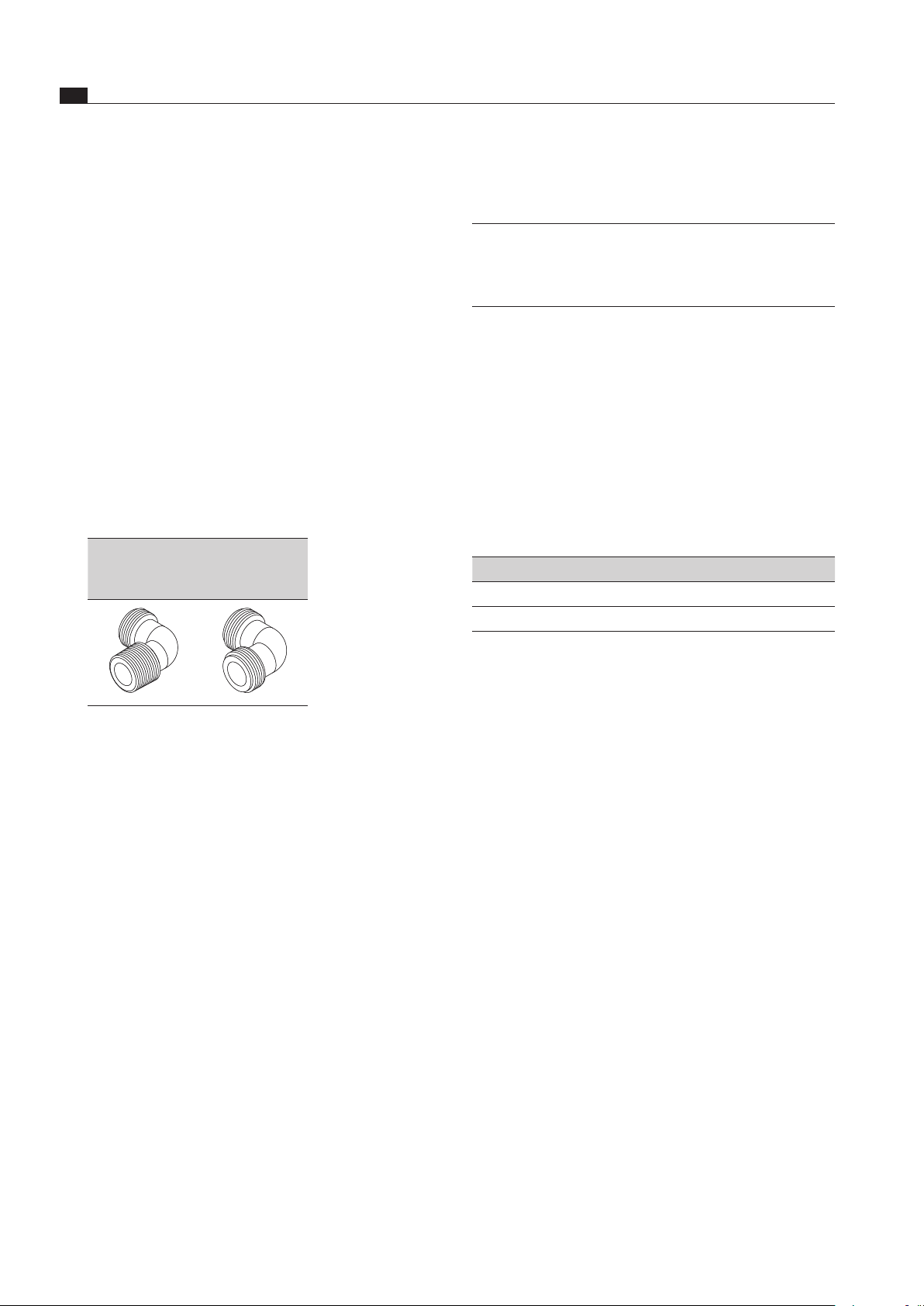
(see table 6.2 Connection bracket).
EN
20
Gas installation
www.bora.com
6.2.1 Additional installation notes for
Australia and New Zealand (AUS/NZS)
INFO Observe the requirements on the installation
of the appliance pursuant to AS/NZS 5601:
minimum clearance of the gas burner head from
flammable surfaces.
Please note all previous information in this section.
In addition, adhere to the requirements of the
currently applicable version of the regulations:
NZS5261/AS5601/AG601.
6.2.2 Gas connection AUS/NZS
Further technical requirements are considered:
AS/NZS 5263.1.1 2016 - Domestic Gas Cooking
Appliances.
Check the extended scope of delivery
Name Quantity
Gas regulator 1,00 kPa with test point for natural gas (NG)
1
Test point adapter for liquid gas (LPG) 1
Tab. 6.1 Extended scope of delivery for AUS/NSZ
Create the gas connection
The connection to a rigid and bend-resistant pipe must
be established as specified in AS/NZS 5601.
Pursuant to AS/NZS 1869 (AGA-certified and authorised)
and AS/NZS 5601, the connection to a safety hose
for gas must have a diameter of 10 mm, a class B or D
classification and a maximum length of 1200 mm.
Connect the appliance as follows:
Switch off the main switch/automatic circuit breaker
before connecting the cooktop.
Protect the main switch/automatic circuit breaker
from being switched on without permission.
Make sure the device is not energised.
Check the gas type and gas pressure of the gas supply
pipe.
Ensure that the appliance is equipped with the correct
nozzle type in order to guarantee a correct burner
flame and safe operation.
Connect the appliance as follows:
Set the control knob to the 0 position.
Close the gas supply.
Switch off the main switch/automatic circuit breaker
before connecting the cooktop.
Protect the main switch/automatic circuit breaker
from being switched on without permission.
Make sure the device is not energised.
Check the gas type and gas pressure of the gas supply
pipe.
Ensure that the appliance is equipped with the correct
nozzle type in order to guarantee a correct burner
flame and safe operation.
Remove the protective cap from the connection tube.
Use a security gas socket to connect this directly
to the connection bracket of the gas cooktop in a gas-
tight manner using a permitted security bracket.
If using a connection bracket, screw this on securely
with the attached seal.
ISO 228-1
ISO 7-1
(EN10226)
ISO 228-1
ISO 228-1
Tab. 6.2 Connection bracket
Only use the type of connection bracket permitted in
your country.
ISO 228-1/ISO7-1(EN10226): cylindrical/conical
ISO 228-1/ISO 228-1: cylindrical/cylindrical
Connect the appliance to the gas supply pipe.
Tighten all connections so that they are secure.
Check that installation has been done correctly.
Check the correct functioning of the stopcock.
Check the tightness of the gas connection by
conducting a leak test (see Leak test section).
Switch on the main switch/automatic circuit breaker.
Put the cooktop into operation (see the Operation
chapter).
Check all the functions and the burner flame are
working correctly.
EN
21
Gas installation
www.bora.com
Set the gas pressure at the gas supply pipe (LPG
pressure bottle) to 2.75 kPa.
Ignite the burner (see the Operation chapter).
Check the burner flame.
Close the gas supply after successfully setting the
pressure.
Set the control knob to the 0 position.
Shut off the measuring device from the test point.
Securely screw the test point screw back into the test
point adapter.
Check that the screw is positioned correctly.
Subsequent installation work for both gas
types (NG/LPG)
Check the tightness of the gas connection by
conducting a leak test (see Leak test section).
Switch on the main switch/automatic circuit breaker.
Put the cooktop into operation (see the Operation
chapter).
Check all the functions and the burner flame are
working correctly.
6.3 Leak test of the gas connection
Ensure that no ignition sparks could be created.
Do not use fire or an open flame.
Use suitable testing equipment to check all the
connections on the gas connections.
When using a leak spray for this process, ensure that
you wet all connections.
Close the gas supply if you determine that gas is
escaping and ventilate the room.
Seal the point from which the gas is leaking.
Re-check all connections and the gas connection.
Repeat the leak test until all connections are tight.
Create a leak test record and give this to the user.
6.4 Changing the gas type
Set the control knob to the 0 position.
Close the gas supply to the gas supply pipe.
Switch off the main switch/automatic circuit breaker.
Protect the main switch/automatic circuit breaker
from being switched on without permission.
Make sure the device is not energised.
Natural gas (NG)
If the cooktop is connected to a natural gas (NG) supply,
a gas regulator must be installed with a test point.
The gas regulator and the transition piece are included in
the scope of delivery of the appliance.
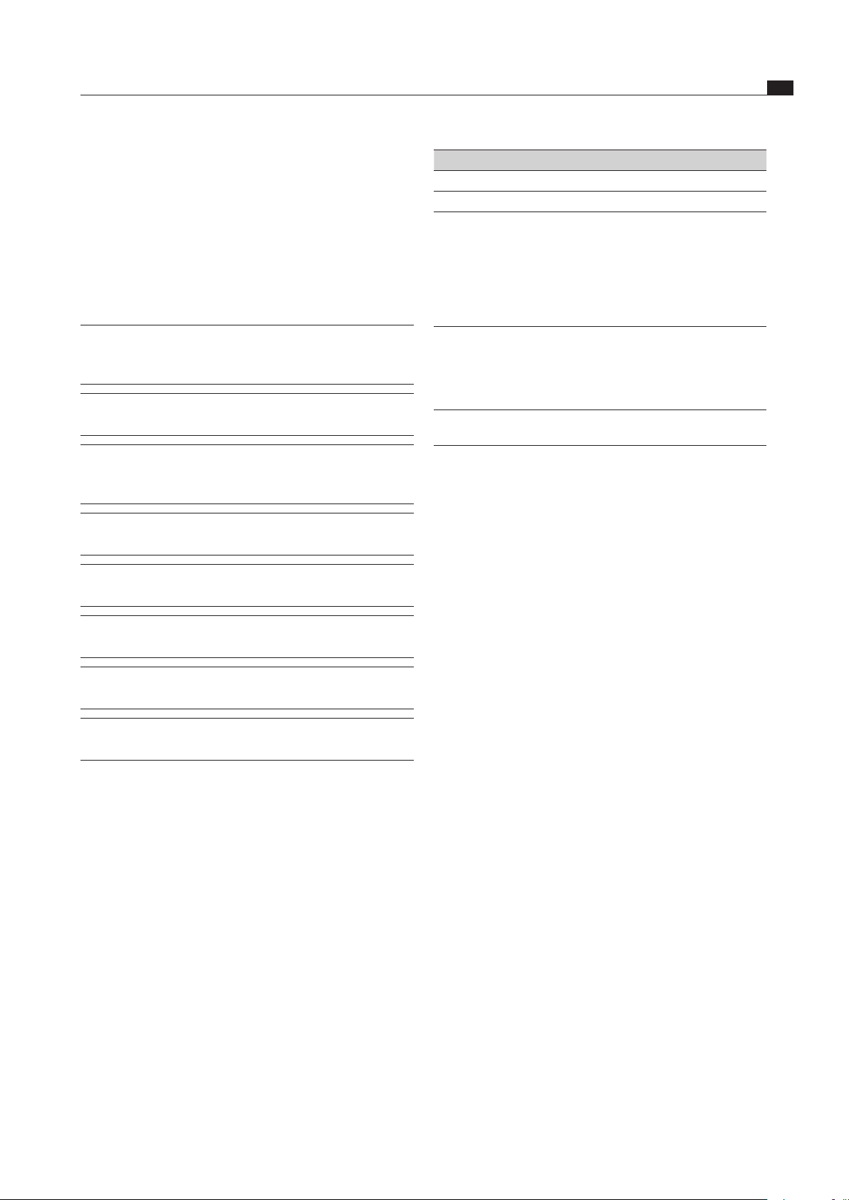
1
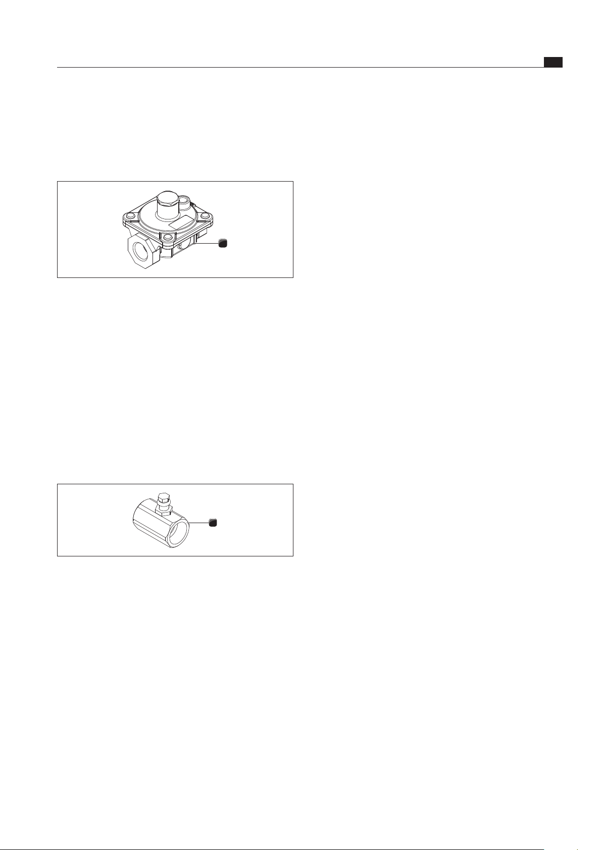
Fig. 6.1 Connection with gas regulator (NG)
[1] Gas regulator
Connect the gas regulator [1] to the connection on
the gas cooktop using the transition pieces and
the suitable seal.
Note the gas flow direction of the gas regulator [1].
Liquid gas (LPG)
If the cooktop is attached to a liquid gas supply (LPG),
the supply is controlled on the gas bottle.
For this purpose, install only the test point adapter
with the transition piece in the gas supply pipe.
The test point adapter and the transition piece are
included in the scope of delivery of the appliance.
1
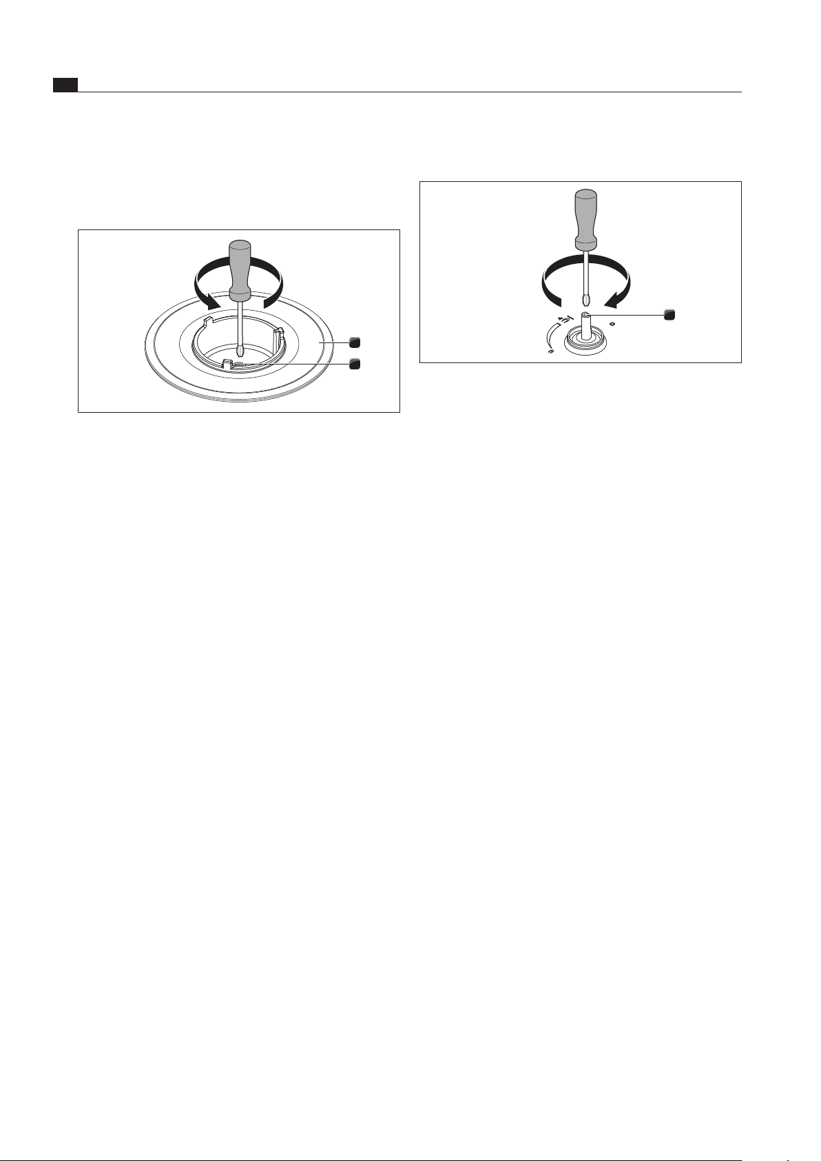
Fig. 6.2 Connection to the test point adapter (LPG)
[1] Test point adapter
Connect the test point adapter [1] to the connection
on the gas cooktop using the transition pieces and the
suitable seal.
Ensure that the seal is positioned correctly.
Provide the necessary transition piece on the supply
side with appropriate seals at the installation site.
Tighten all connections so that they are secure.
Check that installation has been done correctly.
Check the correct functioning of the stopcock.
Check the gas pressure (LPG) as follows:
Set the control knob to the 0 position.
Close the gas supply.
Unscrew the test point screw completely.
Connect your measuring device to the test point
connection.
Open the gas supply.
EN
22
Gas installation
www.bora.com
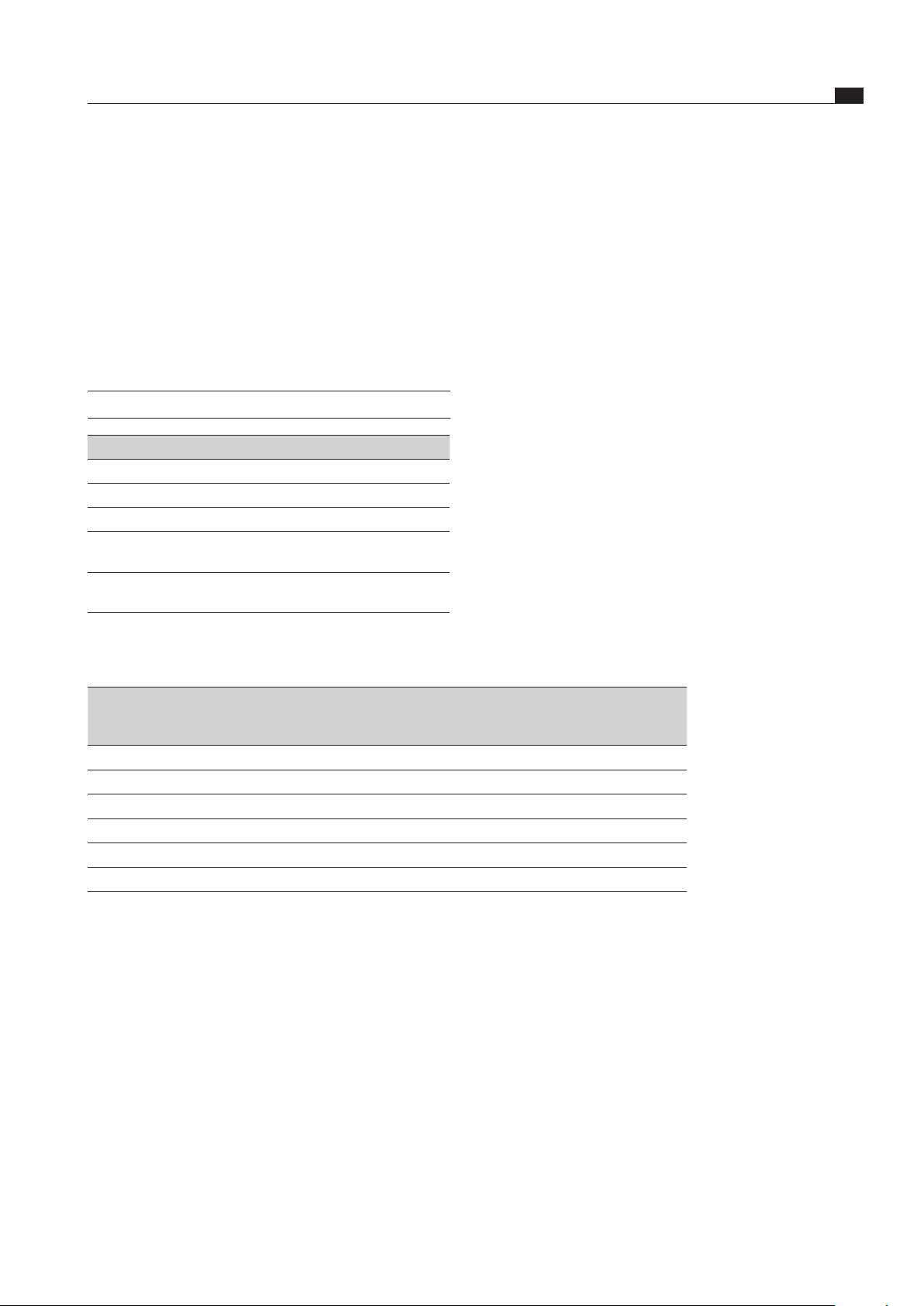
6.4.1 Setting up gas taps
1
Fig. 6.4 Set the gas tap
[1] Throttling screw
Perform minimum setting:
Natural gas (NG)
Prerequisites:
Use of G20 nozzles.
It is not necessary to set up the primary air for the gas
burner.
Ignite the gas burner and set the control knob to the
minimum setting (small flame).
Remove the control knob by pulling it upwards.
Use a screw driver to turn the throttling screw [1] to
the right or left in order to adjust the flame correctly.
Put the control knob back on.
Ensure that the flame does not go out when changing
between the maximum and minimum setting on the
gas burner.
Liquid gas (LPG)
Prerequisites:
Use of G30/G31 nozzles.
The gas burners do not require the primary air to be set.
Remove the control knob by pulling it upwards.
Turn the throttling screw until it stops.
Put the control knob back on.
Ensure that the flame does not go out when changing
between the maximum and minimum setting on the
gas burner.
Changing the gas burner nozzle in the gas
burner:
Remove the pan support.
Remove the gas burner cover
1
2
Fig. 6.3 Cooktop burner with gas burner nozzle
[1] Gas burner
[2] Gas burner nozzle
Unscrew the gas burner nozzle [2] from the gas burner
[1]
Screw the corresponding nozzle for the gas type to be
used into the gas burner [2].
Position the gas burner cover correctly on the gas
burner [1] so that it lies flat.
Affix the new labelling for the gas type used (natural
gas/liquid gas) to the nameplate on the underside of
the appliance.
Install the corresponding gas connection for natural
gas (NG) or liquid gas (LPG). See the Gas connection
section in this chapter.
EN
23
Gas installation
www.bora.com
6.5 Handover to user
Once installation is complete:
Explain the main functions to the user.
Explain all safety-related aspects of operation and
handling to the user.
Provide the user with the accessories and operating
and installation instructions to be kept in a safe place.
6.6 Nozzle table
INFO Use only stamped and approved nozzles.
EU
Gas type/mbar Ø high-power burner Ø normal burner
G20/20 117 Y 75 X
G25/25 125 F3 73 F1
G30/30
G31/37
83 51
G30/50
G31/50
72 M 46 M
Tab. 6.2 Standard nozzle table
AUS/NZS
Gas type
LPG (liquid gas)
NG (natural gas)
Peak pressure
(kPa)
Gas burner
(position)
Nozzle diameter
1/100mm
Heat output
(MJ/n)
G30 butane LPG 2.75 Back 91 11.8
G31 propane LPG 2.75 Back 91 11.8
G20 natural gas NG 01:00 Back 155 12.0
G30 butane LPG 2.75 Front 53 4.4
G31 propane LPG 2.75 Front 53 4.4
G20 natural gas NG 01:00 Front 90 4.1
Tab. 6.3 Australia/New Zealand nozzle table
EN
24
Operation
www.bora.com
7 Operation
Observe all safety and warning information during
operation (see the Safety chapter).
INFO The cooktop may only be operated when the
stainless steel grease filter is installed (see
operating instructions for cooktop extractor).
INFO Clean the cooking zone before using the cooktop
for the first time (see the Cleaning chapter).
INFO As a result of use, the gas burners can
become discoloured. This discolouration
does not affect the gas flame.
INFO When using the gas burner, you may hear gas
escaping from this.
The burner flame turns orange as a result of
impurities on the burner and in the ambient air
(dust). These properties are normal and can occur
independently of one another.
The use of a gas cooktop results in the formation of heat
and moisture in the area where it is installed.
Ensure sufficient ventilation.
Keep natural ventilation openings open.
Use a mechanical ventilation device.
Intensive use of the device for a long time may
require the use of additional ventilation, e.g. opening
a window or effective ventilation, e.g. operation of the
mechanical ventilation device at a higher power level.
Turn off the gas supply and switch off the fuse of the
electrical wiring, in case of smoke development or if
fire breaks out during operation of the gas cooktop.
7.1 Ignite the gas burner
Each gas hob is equipped with a safety thermocouple.
This thermocouple detects if the flame has gone out
and switches off the gas supply.
No more gas will flow.
Fig. 7.1 Push and pull control knob
Ignition
When igniting the gas burner the control knob must
be kept pressed in after ignition for another approx.
15 seconds.
If the flame accidentally goes out or the gas burner has
not ignited, wait for at least one minute before repeating
the ignition process.
Open the upstream gas valve in order to ensure the
gas supply.
Press in the control knob of the desired gas hob as far
as it will go.
Now turn the pressed-in control knob anti-clockwise
(to the left) to the large flame symbol.
The gas now flows from the burner and is ignited safely
by the cycle function.
The flame is extinguished if the control knob is
released too soon.
Keep the control knob pressed for
approx. 10-15 seconds.
A stable flame is now burning.
If the ignition has not worked, try again on the low or
medium setting of the control knob.
Switching off
Turn the control knob to power level 0 to switch off the
gas cooktop.
The gas hob flame is extinguished.
Close the upstream gas valve.
7.2 Adjusting the power level
Turn the control knob to set the respective power level.
7.3 Correct use of the gas hob
INFO Do not put cookware with an uneven base on the
cast iron pan support. Such cookware may tip
over.
For maximum performance with minimum gas
consumption, we recommend:
Use cookware with a base that covers the flame
entirely so that this does not burn beyond the base.
Use suitable pans on each gas burner.
Once the pan contents are simmering, put the gas
burner on the lowest power level (small flame).
Centrally position the cookware on the gas hob.
EN
25
Operation
www.bora.com
7.4 Using the gas cooktop with a
BORA cooktop extractor
INFO The cooktop should only be operated if the cover
plate for its extractor is attached in the correct
position on the extractor frame and can function
as an air baffle.
INFO The cover plate can heat up during use.
Fig. 7.1 The position of the air bae of the CKASE extraction
system
Before use, place both cover plates in the intended
positions on the extractor frame.
This prevents any deformation of the flame.
You can now use the cooktop extractor with a gas
cooktop.
When using two gas cooktops, an additional set,
consisting of two cover plates of the CKASE cooktop
extractor must be used.
EN
26
Cleaning and Maintenance
www.bora.com
8 Cleaning and
Maintenance
Observe all safety and warning information
(see the Safety chapter).
Follow the enclosed manufacturer’s information.
Make sure that the cooktop and cooktop extractor
have been switched off completely and have cooled
down prior to the planned cleaning and maintenance
work to prevent injury (see the Operation chapter).
Regular cleaning ensures the longevity of the product
and optimal functioning.
Adhere to the following cleaning and maintenance
cycles:
Component Cleaning cycle
Control panel
Control knob
immediately after every soiling
Cooktop
Pot holder
Gas burner cover
immediately after every soiling every
week thoroughly with standard
commercially available cleaning agents
Tab. 8.1 Cleaning cycles
8.1 Cleaning agents
INFO Due to the use of aggressive cleaning agents and
abrasion caused by the pot bases the surface will
become damaged and dark stains will occur.
You need a special glass ceramic scraper and suitable
cleaning agents to clean the cooktop.
Never use steam cleaners, abrasive sponges, scouring
pads, or chemically aggressive cleaning agents
(e.g. baking oven spray).
Make sure that the cleaning agent does not contain
any sand, soda, acids or chloride.
8.2 Maintaining the cooktop
Do not use the cooktop as a worktop or shelf.
Do not push or pull cookware across the cooktop.
Always lift pots and pans.
Keep the cooktop clean.
Remove any kind of soiling immediately.
Only use cookware which is suitable for glass ceramic
cooktops (see the Device description chapter).
8.3 Cleaning the cooktop
INFO When the cooktop extractor is switched on, the
stainless steel grease filter must be installed
to ensure that no small and light objects, such
as cleaning wipes made of fabrics or paper are
sucked in (see operating instructions for the
cooktop).
Make sure that the cooktop is switched off (see the
Operating chapter).
Make sure that the gas supply is disconnected/turned
off.
Wait until all cooking zones are cold.
Remove all coarse soiling and food residues from the
cooktop with a glass ceramic scraper.
Apply the cleaning agent onto the cold cooktop.
Rub the cleaning agent with a paper towel or a clean
cloth.
Wipe off the cooktop while wet.
Rub the cooktop dry with a clean cloth.
When the cooktop is hot:
Immediately remove molten residues of plastic,
aluminium film, sugar or foods containing sugar with
a glass ceramic scraper from the hot cooking zone
to prevent burning them in.
Heavy soiling
Remove heavy soiling and stains (limescale stains,
pearly shimmering stains) with cleaning agents while
the cooktop is still warm.
Soften dried dirt residues using a damp cloth.
Remove dirt residues with the glass ceramic scraper.
Always remove grains, crumbs or similar which fall
onto the cooktop during general cooking work right
away to prevent the surface from being scratched.
Coloured changes and shiny surfaces are not cooktop
damage. They do not impact on the function of the
cooktop and the stability of the glass ceramic.
Discolourations to the cooktop arise from residues which
are not removed and have been burnt in.
Glossy spots are caused by unsuitable cleaning agents.
They are very hard to remove.

EN
27
Cleaning and Maintenance
www.bora.com
8.3.1 Cleaning of the gas burners
1
2
3
4
5
6
Fig. 8.1 Gas burner installation
[1] Burner cover
[2] Burner head
[3] Safety thermocouple
[4] Electrical ignition device
[5] Burner housing
Do not clean the device until the gas burner has cooled
down to normal temperature after use.
Clean the device only with normal hot rinse water and
a commercially available detergent by means of a soft
sponge or a normal dishcloth.
Never scrape or scratch off cooking residues.
Do not put the gas burner parts and the pot holder in
the dishwasher for cleaning.
Remove the pot holder.
Remove the burner cover [1] from the burner head [2].
Remove the burner head [2] from the gas outlet valve
Clean the burner parts.
Put the burner parts back together again after
cleaning.
The burner heads and burner covers must be
completely dry before they are put back in place.
Position the burner head [2] correctly on the gas outlet
valve.
Make sure that the safety thermocouple and the
electrical ignition device are positioned in the correct
opening.
Put the burner cover [1] straightly and evenly on the
burner head [2].
The electrical ignition will not work if burner parts are
not put back in place correctly.
Put the pot holder straightly and evenly on the gas
cooktop.
Put the gas burner into operation (see the Operation
chapter).
8.3.2 Cleaning the control knobs
Ensure that the cooktop is switched off
(see the Operating chapter).
Clean only the control knob by hand.
Pull off the control knob.
Clean the control knob with a soft brush.
Rinse the control knob well after cleaning.
Allow the control knob to dry thoroughly.
Re-insert the clean and dry control knob into the slot
after the cleaning is completed.
EN
28
Troubleshooting
www.bora.com
9 Troubleshooting
Observe all safety and warning information (see the Safety chapter).
Operating situation Cause Remedy
The cooktop cannot be
ignited electrically.
The fuse or automatic circuit breaker of the
apartment and/or house‘s electrical system is
defective or has been triggered.
Replace the fuse.
Switch the safety cut-out back on.
The fuse or the automatic circuit
breaker trips several times.
Call the BORA Service Team.
The power supply is disconnected. Have a specialist electrician inspect the
power supply.
The gas burners are damp. Dry the gas burner parts
(see the Cleaning chapter).
The gas burner heads and/or the
gas burner cover are not correctly positioned.
Position the gas burner parts correctly
(see the Cleaning chapter).
Dirt in the gas burner head Clean the gas burner parts
(see the Cleaning chapter).
You notice the smell of gas. A leakage point in the gas supply line Switch off the gas supply and
immediately extinguish all open flames.
Contact a gas engineer.
Ensure that all connections are tight
(see the Gas installation chapter).
No gas is coming out of the
gas burners.
The gas supply is closed Open the gas supply
(see the Operation chapter).
The gas bottle is empty in the case of
liquid gas (LPG).
Exchange the empty gas bottle for a full
gas bottle of the correct gas type.
You notice that the flame of the
burner is uneven.
The gas burner heads and/or the
gas burner cover are not correctly positioned.
Position the gas burner parts correctly
(see the Cleaning chapter).
Dirt in the gas outlet openings on the gas
burner head.
Clean the gas burner parts
(see the Cleaning chapter).
Tab. 9.1 Resolving a fault
In all other instances, call the BORA Service Team (see the Warranty, service and spare parts chapter).
EN
29
Decommissioning, disassembly and disposal
www.bora.com
10 Decommissioning,
disassembly and
disposal
Observe all safety and warning information
(see the Safety section).
Follow the enclosed manufacturer’s information.
10.1 Decommissioning
Decommissioning is understood as final shutdown and
disassembly. Following decommissioning, the device can
either be installed into other units, sold on privately or
disposed of.
INFO Electricity and gas connections may only be
disconnected by qualified specialists.
To decommission, switch the device off
(see Operation section)
Disconnect the device from the power supply.
Disconnect the device from the gas supply.
10.2 Disassembly
For removal, the device must be accessible for
disassembly and disconnected from the power supply.
For gas devices, make sure the gas connection is
disconnected.
Undo the mounting brackets.
Remove the silicone joints.
Remove the device from the worktop by lifting it
upwards.
Remove any other accessories.
Dispose of the old device and any contaminated
accessories as described under “ Environmentally-
friendly disposal”.
10.3 Environmentally-friendly disposal
Disposal of transport packaging
INFO The packaging protects the device from damage
in transport. The packaging materials have
been selected from environmental and disposal
perspectives and are therefore recyclable.
Returning the packaging to the materials cycle saves
resources and reduces waste volumes. Your specialist
supplier will take the packaging back.
Give the packaging to your specialist supplier
or
Dispose of the packaging properly in line with local
regulations.
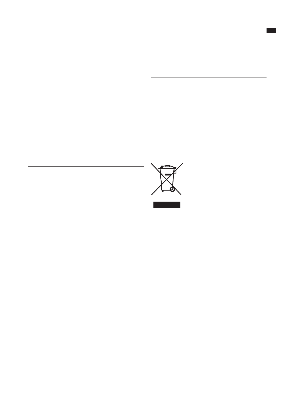
Disposal of old appliance
Electrical devices marked with this label
may not be disposed of in domestic
waste at the end of their service
life. They must be disposed of at a
collection point for the recycling of old
electrical or electronic devices. You
can find information from your city or
district council.
Many electrical and electronic devices still contain
valuable materials. But they also contain damaging
materials which were necessary for them to function
properly and safely. These can damage human health or
the environment if disposed of improperly or incorrectly
handled.
Never put your old appliance in domestic waste.
Take the old appliance to a regional collection point
for return and recycling electrical and electronic
components and other materials.
EN
30
Warranty, technical service, spare parts
www.bora.com
11 Warranty, technical
service, spare parts
Observe all safety and warning information (see the
Safety chapter).
11.1 BORA manufacturer’s warranty
BORA provides its end customers with a 2-year
manufacturer’s warranty for its products. The end
customer is entitled to this warranty in addition to the
statutory claims for defects against the sellers of our
products.
The manufacturer’s warranty applies to all BORA products
sold by authorised BORA dealers with the European
Union, with the exception of products labelled by BORA
as Universal products or accessories.
The manufacturer’s warranty starts as soon as the
BORA product is handed over to the end customer by
an authorised BORA dealer and is valid for 2 years. By
registering on www.mybora.com the end customer has
the possibility of extending the manufacturer’s warranty
to 3 years.
The manufacturer’s warranty requires expert (in
accordance with the valid BORA ventilation handbook
and operating instructions at the time of installation)
installation of the BORA products by an authorised BORA
dealer. During use, the end customer is to adhere to the
specifications and instructions in the operating manual.
In order to file a warranty claim, the end customer is to
notify their dealer or BORA of the fault and must present
the receipt. Alternatively, the end customer can provide
proof of purchase by registering on www.mybora.com.
BORA guarantees that all BORA products are free from
material and product defects. The defect must exist prior
to delivery of the product to the end customer. In the
event that a warranty claim is filed, the warranty shall not
commence anew.
BORA will correct defects in BORA products at its own
discretion by repairing or replacing the product. All costs
for the correction of defects under the manufacturer’s
warranty shall be assumed by BORA.
Expressly not covered by the BORA manufacturer’s
warranty are:
BORA products that were not sold by authorised BORA
dealers
Damage caused by non-adherence to the operating
instructions (including product care and cleaning) This
represents improper use.
Damage caused by normal use, e.g. traces of usage on
the cooktop
Damage caused by external influences (such as
transport damage, ingress of condensation, damage
caused by the elements such as a lightning strike)
Damage caused by repairs or attempts to repair not
made by BORA or persons authorised by BORA
Damage to the glass ceramic
Voltage fluctuations
Secondary damage or claims for damages beyond the
defect
Damage to plastic parts
Legal claims, particularly statutory claims for defects
or
product liability are not limited by the warranty.
If a defect is not covered by the manufacturer’s warranty,
the
end customer can employ the services of the BORA
technical service, however, they must cover the costs
themselves.
The laws of the Federal Republic of Germany apply to
these warranty conditions.
You can contact us by:
Telephone: +49 800 7890 0987 Monday to Thursday
from 08:00-18:00 and Friday from 08:00-17:00
Email: [email protected]
11.2 Service
BORA Service:
see reverse side of operating and assembly instructions
+800 7890 0987
In the case of faults you cannot fix yourself, contact
your BORA specialist supplier or the BORA Service
Team.
The BORA Service Team will require the type designation
and serial number of your device (FD number). This
information is provided on the nameplate on the back of
the instructions as well as on the bottom of the device.
11.3 Spare parts
Only use original spare parts for repairs.
Repairs may only be carried out by the BORA Service
Team.
INFO Spare parts can be obtained from your BORA
dealer, the BORA online service website at www.
bora.com/service or by calling the service
number provided.


Germany:
BORA Lüftungstechnik GmbH
Rosenheimer Str. 33
83064 Raubling
Germany
T +49 (0) 8035 / 9840-0
F +49 (0) 8035 / 9840-300
www.bora.com
Austria:
BORA Vertriebs GmbH & Co KG
Innstraße 1
6342 Niederndorf
Austria
T +43 (0) 5373 / 62250-0
F +43 (0) 5373 / 62250-90
www.bora.com
Europe:
BORA Holding GmbH
Innstraße 1
6342 Niederndorf
Austria
T +43 (0) 5373 / 62250-0
F +43 (0) 5373 / 62250-90
www.bora.com
Australia - New Zealand:
BORA APAC Pty Ltd
100 Victoria Road
Drummoyne NSW 2047
Australia
T +61 2 9719 2350
F +61 2 8076 3514
www.bora-australia.com.au
Nameplate:
(please affix)
+800 7890 0987