MILWAUKEE ELECTRIC TOOL CORPORATION
13135 W. Lisbon Road, Brookfield, WI 53005
Drwg. 4
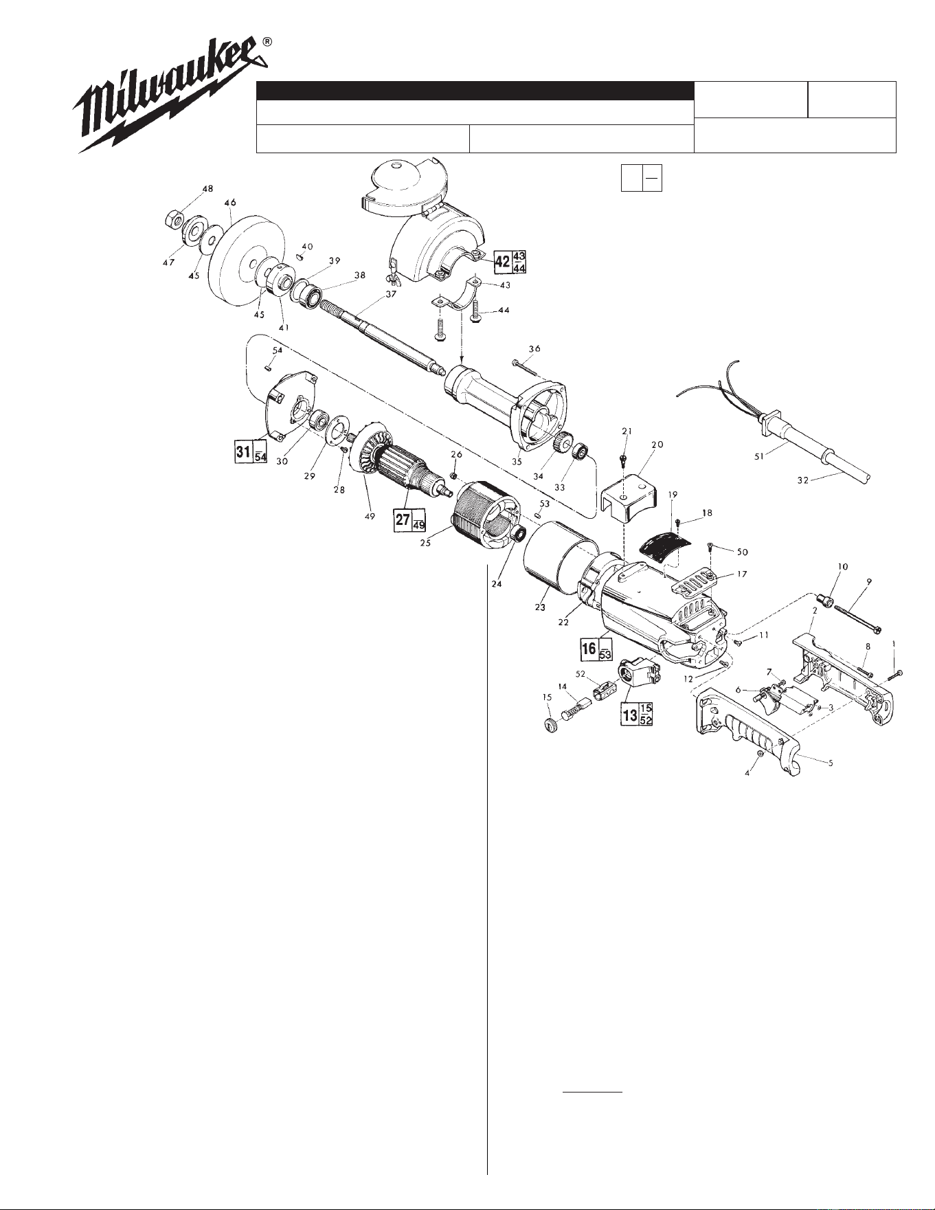
FIG. PART NO. DESCRIPTION OF PART QTY.
1 06-82-2378 10-24 x 1" Pan Head Screw (3)
2 31-44-0606 Right Handle Half (1)
! 3 05-78-0305 T-15 Switch Screw (2)
4 06-55-1050 10-24 Hex Nut (3)
5 31-44-0607 Left Handle Half (1)
! 6 23-66-1798 Switch (1)
! 7 06-82-7409 8-16 x 1/2" Pan Hd. Plastite Torx Screw (1)
! 8 06-82-5574 10-24 x 7/8" Pan Hd. Taptite Screw T-25 (4)
! 9 06-82-9600 10-32 x 3" Fil. Flat Hd. Screw (2)
10 31-86-0160 Insulating Bushing (2)
11 06-95-5200 Ground Screw (1)
! 12 06-82-7252 8-32 x 3/8" Taptite Screw (2)
13 22-22-0401 Brush Holder Assembly (2)
! 14 22-18-0730 Carbon Brush Assembly (2)
15 23-44-0170 Brush Retaining Cap (2)
16 28-50-6351 Motor Housing Assembly (1)
17 31-15-0310 Cover Plate (1)
18 06-85-0200 Nameplate Screw (2)
19 12-99-0241 Nameplate Blank (1)
20 31-70-0135 Tool Rest (1)
! 21 45-04-0720 Shoulder Screw (2)
22 31-55-0110 Coil Shield (1)
23 23-16-0950 Insulating Sleeve (1)
! 24 02-04-0913 Ball Bearing (1)
25 18-70-0100 120 Volt Field (1)
26 06-57-3005 10-32 Locking Hex Nut (2)
27 16-70-0155 120 Volt Armature (1)
! 28 06-82-7252 8-32 x 3/8" Taptite Screw (3)
29 44-86-0320 Ball Bearing Retainer (1)
! 30 02-04-1515 Ball Bearing (1)
31 28-28-0392 Diaphragm Assembly (1)
32 22-64-3000 Cord Set (1)
33 02-04-0910 Ball Bearing (1)
34 32-75-3160 Spindle Gear (1)
35 28-50-0400 Spindle Housing (1)
! 36 06-82-5514 1/4-20 x 1-1/2" Taptite Screw (4)
37 38-50-5280 Spindle (1)
! 38 02-04-1745 Ball Bearing (1)
39 34-80-2700 Internal Retaining Ring (1)
40 06-42-1200 Woodruff Key (1)
41 43-34-0320 Inner Wheel Flange (1)
FIG. NOTES
6 Assemble Switch to Left Handle Half.
FIG. LUBRICATION
35 Important! Completely clean out old grease from the
spindle housing and replace with 1-1/2 Oz. Type "Y" Grease,
No. 49-08-5270.
58-01-1307
5243
54-22-1032
663B
6" STRAIGHT GRINDER
54-22-1031
EXAMPLE:
Component Parts (Small #) Are Included
When Ordering The Assembly (Large #).
REVISED BULLETIN
DATE
SERVICE PARTS LIST
BULLETIN NO.
WIRING INSTRUCTION
CATALOG NO.
SPECIFY CATALOG NO. AND SERIAL NO. WHEN ORDERING PARTS
STARTING
SERIAL NUMBER
May 2005
0
0
0
FIG. PART NO. DESCRIPTION OF PART QTY.
42 49-12-0160 6" Wheel Guard (1)
! 43 42-68-0230 Clamp (1)
! 44 06-81-4710 5/16-18 Grade 8 Bolt (2)
45 45-88-0260 Flange Rubber Washer (2)
46 --------------- 6" Grinding Wheel (see catalog) (1)
47 43-34-0330 Outer Wheel Flange (1)
48 06-55-3250 5/8-11 Hex Nut (1)
49 22-84-0690 Fan (1)
! 50 06-82-3792 8-32 x 3/8" Oval Hd. Taptite Screw (2)
51 44-76-0170 Cord Protector (1)
52 22-20-0360 Brush Tube (2)
53 45-30-0120 Ball Bearing Retaining Slug (1)
54 45-30-0070 Ball Bearing Retaining Slug (1)
49-96-7230 Spanner Wrench (1)
49-96-4072 1-1/16" Open End Wrench (1)
!= Part number change from previous
service parts list.