
32
33
4x
2x
4x
13
29 32 33 34
35 36 38
1
7
8
29
40
31
10
10
30
50
30
12
14
15
4x
4x
38
2
34
35
36
37
20
20 37
39
3
2x
2
22
26
21
2
23
39
5
53
5
52
4
54
55
56
57
58
59
60
61
62
17
28
2x
16
27
19
18
2x
25
MILWAUKEE TOOL
l
www.milwaukeetool.com
13135 W. Lisbon Road, Brookeld, WI 53005
Drwg. 2
BULLETIN NO.
54-38-6133
SERVICE PARTS LIST
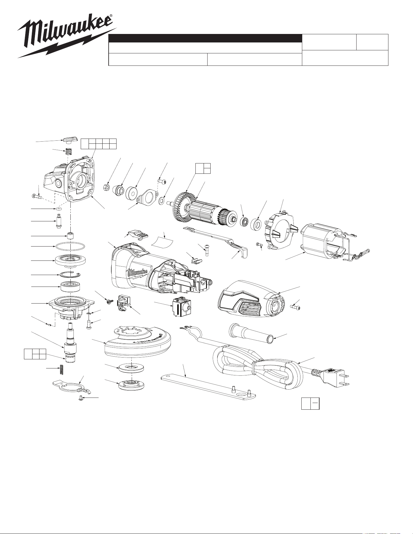
FIG. PART NO. DESCRIPTION OF PART NO. REQ.
1 14-30-0155 Gearcase Assembly (1)
2 05-88-1200 M4 x 16 Pan Hd. Plastite T-20 Screw (7)
3 14-73-0055 5/8-11 Spindle/Hub Assembly (1)
4 34-80-0210 Retaining Ring (1)
5 06-82-2380 #8-32 x 1/2” Pan Hd. Slt. Tapt. T-20 Screw (6)
7 05-55-0620 Nut (1)
8 32-60-0275 Bevel Pinion (1)
10 --------------- Armature (1)
12 42-96-0177 Rubber Bearing Cup (1)
13 06-82-3002 Pan Hd. Taptite T-10 ST Screw (4)
CATALOG NO. 6130-33
REVISED BULLETIN
SPECIFY CATALOG NO. AND SERIAL NO. WHEN ORDERING PARTS
4.5” (115mm) ANGLE GRINDER
STARTING
SERIAL NO.
DATE
May 2022
WIRING INSTRUCTION
C27D
EXAMPLE:
Component Parts (Small #)
Are Included When Ordering
The Assembly (Large #).
0
00
SEE PAGE 3
54-38-6132
FIG. PART NO. DESCRIPTION OF PART NO. REQ.
34 34-40-0270 O-Ring (1)
35 --------------- Spindle Lock Pin (1)
36 42-40-0025 Bushing (1)
37 --------------- Bevel Gear (1)
38 --------------- Gearcase (1)
39 --------------- 5/8-11 Spindle (1)
40 44-86-0155 Retaining Plate (1)
50 16-10-0120 Armature Assembly (1)
52 49-96-0130 Spanner Wrench (1)
53 34-40-0330 O-Ring (1)
54 --------------- Ball Bearing (1)
55 --------------- Spring Pin (1)
56 05-90-0225 Spring Washer (1)
57 40-50-0780 Spring (1)
58 44-20-0065 Locking Tang (1)
59 05-81-0020 M3 x 6 Philips #2 Taptite Screw (1)
60 44-40-0215 5/8-11 Outer Disk Flange (1)
61 44-40-0245 5/8-11 Inner Disk Flange (1)
62 43-54-0155 4.5” T27 Guard (Standard) (1)
43-54-0185 4.5” T1 Guard (Not Shown) (Optional) (1)
42-62-0110 Side Handle (Not Shown) (1)
FIG. LUBRICATION (*See lubrication note above):
8,37 Type “Y” Grease, No. 49-08-5270, Must Be Applied
To All Gear Teeth.
4,38 Lightly coat with grease Retaining Ring and bearing bore
in Gearcase.
38 .4 Ounces (13 Grams) Type “Y” Grease, No. 49-08-5270.
* LUBRICATION NOTE: When servicing the Gears (8 & 37) or the
Gearcase (38), 90-95% of the old grease must be removed prior to
new grease being added.
«
«
«
«= Part number change from
previous service parts list.
«
«
«
«
«
«
«
«
«
«
«
«
«
«
«
«
«
«
«
«
«
«
«
«
«
«
FIG. PART NO. DESCRIPTION OF PART NO. REQ.
14 42-14-0035 Bae (1)
15 18-07-0176 Service Field Assembly (1)
16 31-50-0261 Motor Housing (1)
17 12-20-0115 Service Nameplate Kit (1)
18 05-88-1100 M3 x 10 Pan Hd. T-10 Screw (2)
19 22-22-0085 Carbon Brush Assembly (2)
20 --------------- Lower Gearcase Hub (1)
21 31-44-0795 Rear Handle (1)
22 44-76-0210 Cord Protector (1)
23 22-64-0565 Cordset (1)
25 23-66-0385 Switch (1)
26 31-17-0040 Cord Clamp (1)
27 31-92-0075 Slide Switch Button (1)
28 31-92-0065 Slide Pole (1)
29 --------------- Ball Bearing (1)
30 02-04-0110 Ball Bearing (1)
31 45-88-1995 Flat Washer (1)
32 --------------- Spindle Lock Button (1)
33 40-50-1330 Spring (1)
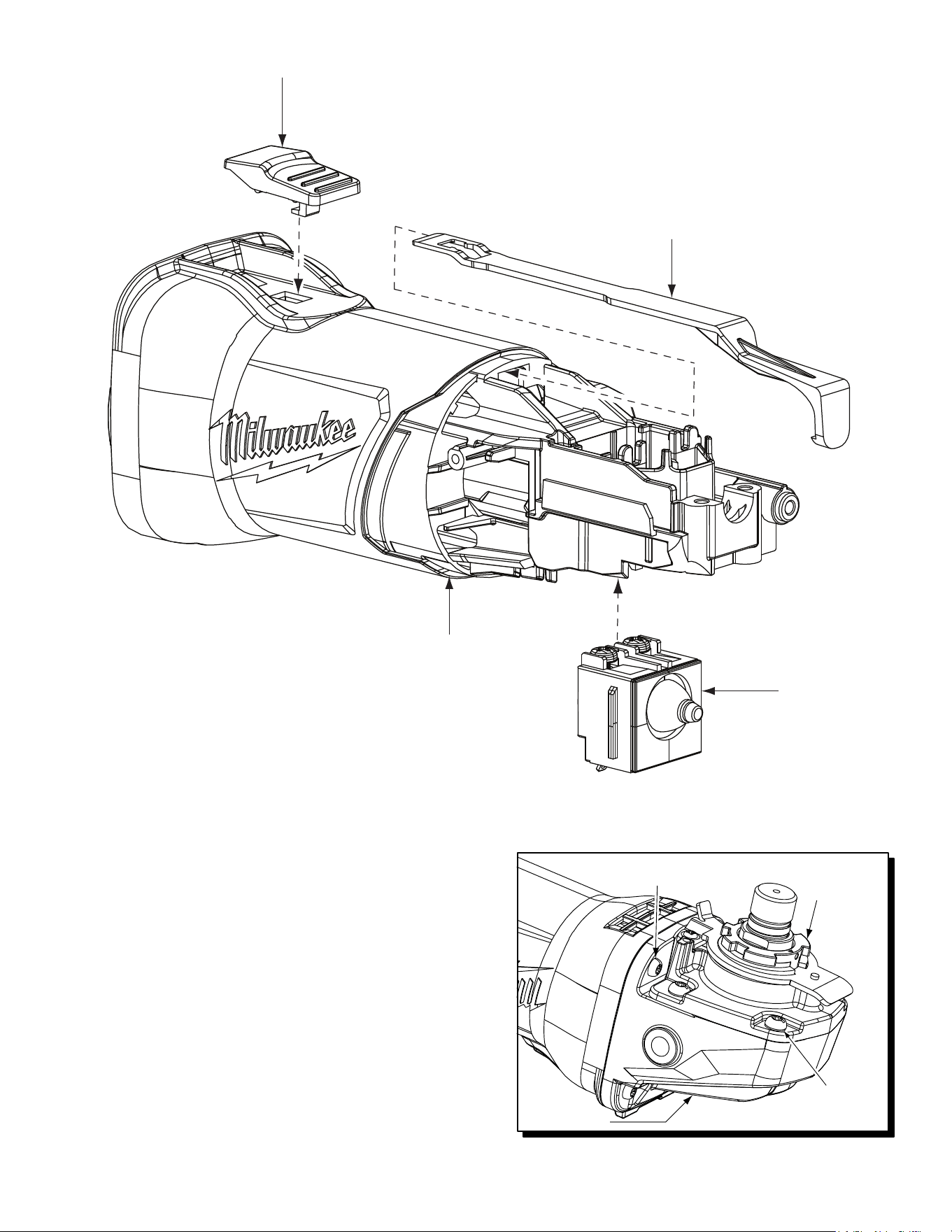
Slide Switch
Button (27)
Switch (25)
Switch Pole (28)
Motor Housing (16)
To remove Slide Switch Button (27), position a at blade screwdriver
along the center of the gearcase (38). Place blade under the locking
tab of the Switch Blade Button and gently pry upward.
Be sure that push button of the Switch (25) is placed into the corre-
sponding recess of the Switch Pole (28).
When reassembling the Slide Switch Button (27) be sure to orient with
the locking tab as shown, towards the gearcase (38).
When servicing the Motor Housing (16) or the Switch Pole (28) it is
recommended to snap the Slide Switch Button (27) into the Switch
Pole, as shown prior to installing the Field (15).
When servicing the Gearcase (38), rst remove the four Screws (5)
and Lower Gearcase Hub (20) to prevent damage to the bottom two
Screws (2) that secure the Gearcase.
Gearcase (38)
Lower
Gearcase
Hub (20)
Gearcase Screws (2)
4 places
Lower Gearcase
Hub Screws (5)
4 places
4
3
5 6
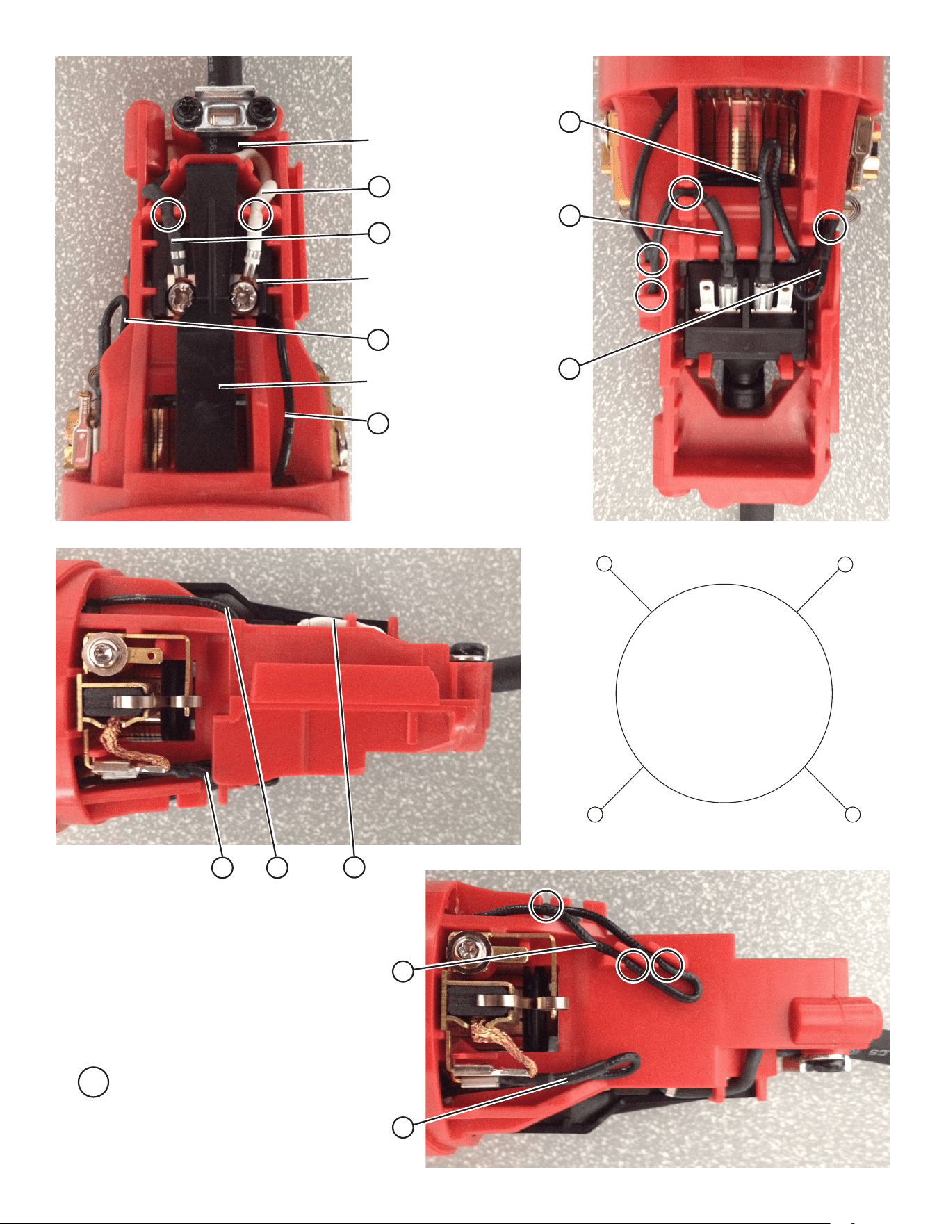
BACK VIEW OF FIELD
RIGHT VIEW
LEFT VIEW
TOP VIEW
BOTTOM VIEW
Slide Pole
Switch
= WIRE TRAPS
1
2
Cord jacket to extend
approx. .125” beyond
cord clamp area
4
3
3
6
4
6
2
35
AS AN AID TO REASSEMBLY,
TAKE NOTICE OF WIRE ROUTING AND
POSITION IN WIRE GUIDES AND TRAPS
WHILE DISMANTLING TOOL.
BE CAREFUL AND AVOID PINCHING
WIRES BETWEEN HANDLE HALVES
WHEN ASSEMBLING.
5