
Y
PIONEER
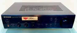
The
Art
of
Entertainment
P2005
105
STEREO
AMPLIFIER
(
PHONEERE
cence
smvene
\
208
f=}
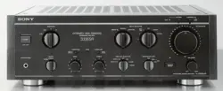
The
illustration
shows
model
A-205.
Operating
instructions
WARNING
:
to
prevent
FIRE
OR
SHOCK
HAZARD,
DO
NOT
EXPOSE
THIS
APPLIANCE
TO
RAIN
OR
MOISTURE.
The
lighting
flash
with
arrowhead,
within
an
equilateral
triangle,
is
intended
to
alert
the
user
to
the
|
presence
of
uninsulated
"dangerous
voltage"
within
the
product's
enclosure
that
may
be
of
sufficient
magnitude
to
constitute
a
risk
of
electric
shock
to
persans.
CAUTION
RISK
OF
ELECTRIC
SHOCK
DONOT
OPEN
CAUTION:
TO
PREVENT
THE
RISK
OF
ELECTRIC
SHOCK,
DO
NOT
REMOVE
COVER
(OR
BACK}.
NO
USER-
SERVICEABLE
PARTS
INSIDE.
REFER
SERVICING
TO
QUALIFIED
SERVICE
PERSONNEL.
The
exclamation
point
within
an
equilateral
tiangle
is
intended
to
alert
the
user
to
the
presence
of
important
Operating
and
maintenance
(servicing)
instructions
in
the
literature
accompanying
the
appliance.

OF
iONE
IONE
iONE
|ONE
ONE
I6B0
a20v 2aov
ov
120127¥
VOLTAGE
SELECTOR
|
2
<ARE7O74>
En
Thank
you
for
buying
this
Pioneer
product.
Please
read
through
these
operating
instructions
so
you
wil]
know
how
to
operate
your
model
properly.
After
you
have
finished
reading
the
instructions,
put
them
away
in
a
safe
place
for
future
reference.
in
some
countries
or
regions,
the
shape
of
the
power
plug
and
power
outlet
may
sometimes
differ
from
that
shown
in
the
explanatory
drawings.
However,
the
methad
of
connecting
and
operating
the
unit
is
the
same.
(——
CONTENTS
-
FEATURES
INSTALLATION,
PANEL
FACILITIES
CONNECTIONS
OPERATIONS.
TROUBLESHOOTING
SPECIFICATIONS
___
FEATURES
e@High
power
output
Model
A-105
Model
A-205
.
30
W
+
30
W/8
2
(DIN)
.
55
W
+
55
W/4
22
(DIN)
45
W
+
45
W/8Q
(DIN)
Wide-Range
Linear
Circuit
This
new
current
feedback
circuit
assures
improved
operating
stability
for
flat
output
impedance
and
stable
driving
of
speakers
across
the
full
range
of
frequencies.
e@The
use
of
a
DIRECT
circuit
ensures
high
fidelity
playback
of
consistent
frequency
characteristics,
with
maximum
clarity,
@
Bi-directional
dubbing
is
possible
by
using
two
cassette
decks.
e@
Speaker
terminals
for
two
speaker
systems
are
provided.
{A-
205
only)
LINE
VOLTAGE
SELECTOR
SWITCH
Only
multi-voltage
model
is
provided
with
this
switch.
Round
2-pin
AC
plug
model
is
not
provided
with
this
switch.
Main
voltages
in
Saudi
Arabia
are
127
V
and
220
V
only.
Never
use
this
model
with
110
V
setting
in
Saudi
Arabia.
The
line
voltage
selector
switch
is
on
the
rear
panel,
Check
that
it
is
set
properly
before
plugging
the
power
cord
into
the
AC-wall
socket.
If
the
voltage
is
not
properly
set
or
if
you
move
to
an
area
where
the
voltage
requirements
differ,
adjust
the
selector
switch
|
as
follows:
1.
Use
a
medium-size
screwdriver.
2.
Insert
the
screwdriver
into
the
groove
on the
voltage
selector,
and
adjust
so
that
the
tip
of
the
arrow
points
to
the
voltagé
value
of
your
area.

1OF
IONE
JONE
ONE
ONE
ONE
I6BO
4
<ARET074>
En
INSTALLATION
_
—
|
LOCATION
__
Install
the
unit
in
a
well-ventilated
location
where.
it
will
not
be
exposed
to
high
temperatures
or
humidity.
Do
not
install
the
unit
in
a
location
which
is
exposed
to
direct
rays
of
the
sun,
or
near
hot
appliances
or
radiay
tors,
Excessive
heat
can
adversely
affect
the
cabinet,
and
internal
components.
Installation
of
the
unit
ina
damp
or
dusty
environment
may
result
in
@
malfunction:
or
accident.
(Also
avoid
installation
near
cookers,
ete.
where
the
unit
may
be
exposed
to
smoke
from,
Gil,
steam,
or
heat.)
Do
not
install
the
unit
on
a
tottered
stand,
nor
on
an
unstable
or
inclined
surface.
VENTILATION
@
When
installing
this
unit,
make
sure
to
leave
spacearound
the
unit
for
ventilation
to
improve
heat
radiation.
If
not
enough
space
is
provided
between
the
unit
and
walls
or
other
equipment,
heat
will
build
up
inside,
interfering
with
performance
or
causing
malfunctions.
ue
If
this
unit
is
used
in
@
stack
of
components,
please
be
sure
to
install
it
at
the
very
top
of
the
stack.
oe
@
Do
not
place
on
a
thick
carpet,
bed,
sofa
or
fabric
having
a
thick
pile.
Do
not
cover
with
fabric
or
other
covering.
Anything
that
blocks
ventilation
will
cause
internal
temperature
to
rise,
which
may
lead
to
breakdown
or
fire
hazard.
[
POWER-CORD
CAUTION
Handle
the
power
cord
by
the
plug.
Do
not
pull
out
the
plug
by
tugging
the
cord
and
never
touch
the
powe
cord
when
your
hands
are
wet
as
this
could
cause
short
circuit
or
electric
shock,
Do
not
place
the
unit,
é
piece
of
furniture,
etc.,
on
the
power
cord,
or
pinch
th
cord.
Never
make
a
knot
in
the
cord
or
tie
it
with
othe!
cords.
The
power
cords
should
be
routed
such
that
the
are
not
likely
to
be
stepped
on.
A
damaged
power
cor
can
cause
fire
or
give
you
an
electrical
shock.
Chee!
the
power
cord
once
in
a
while.
When
you
find
i
damaged,
ask
your
nearest
PIONEER
authorized
servic
center
or
your
dealer
for
a
replacement.
MAINTENANCE
OF
EXTERNAL
SURFACES
Use
a
polishing
cloth
or
dry
cloth
to
wipe
off
dust
and
dirt:
When
the
surfaces
are
very
dirty,
wipe
with
a
soft
cloth
dipped
in
some
neutral
cleanser
diluted
five
or
Six
times
with
water,
and
wrung
out
well,
and
thet
wipe
again
with
a
dry
cloth.
Do
not
use
fur
nitue|e
wax
of
cleaners.
eNever
use
thinners,
benzine,
insecticide
sprays
and
other
chemicals
on
or
near
this
unit,
since
L
these
will
corrode
the
surfaces.
eae
ae

OF
NE
NE
NE
NE
NE
1
The
illustration
shows
model
A-205.
Mode!
A-108
is
not
equipped
with@and®.
6
<ARE7074>
En
+
FRONT
PANEL
See
Fig.[1]
@POWER
switch
Press
to
turn
power
to
the
unit
ON
and
OFF.
@
Input
Selector
switch/indicator
Use
to
select
the
playback
source.
PHONO
:
For
record
playback
with
a
turntable.
cD
:
For
compact
disc
playback
with
a
CD
player.
TUNER
:
For
AM
or
FM
broadcast
reception
with
a
tuner,
LINE
:
Set
to
this
position
when
listening
to
the
program
from
a
component
connected
to
the
LINE
terminals.
TAPE
1/DAT
:
For
playback
with
a
cassette
deck
or
digital
audio
tape
deck
connected
to
the
TAPE
1/DAT
terminais,
@VOLUME
control
Use
to
adjust
the
volume
jevel.
@TAPE
2
MONITOR
switch/indicator
Use
when
there
is
an
adaptor
component
(graphic
equalizer,
etc.)
or
cassette
deck
connected
to
the
TAPE
2
MONITOR
terminals.
ON
:
Indicator
Sights
when
using
the
adaptor
component.or
listening
to
the
cassette
deck.
OFF:
indicator
goes
out
when
notin
use.
NOTES:
@
When
no
connections
are
made
to
the
TAPE
2
MONITOR
terminals
or
when
they
are
not
in
use,
be
sure
to
set
this
switch
to
the.
OFF
position.
(No
sound
will
be
heard
if
it
is
set
to
the
ON
position.)
When
the
TAPE
2
MONITOR
indicator
is
on
and
the
input
selecto!
switch
is
not
set
to
TAPE
1/DAT,
the
signals
which
are
inpu'
through
TAPE
2
MONITOR
are
then
output
at
TAPE
1/DAT
REC
OUT.

oF
NE
NE
NE
NE
NE
BO
The
illustration
shows
model
A-205.
@
@
PIINGER
sreneoaneunen
A205
®
a
a
Mo
@®
®
Model
A-105
is
not
equipped
with@and@.
6
<ARE7074>
En
FRONT
PANEL
eee
as
See
Fig.[1]
@
POWER
switch
Press
to
turn
power
to
the
unit
ON
and
OFF.
@Input
Selector
switch/indicator
Use
to
select
the
playback
source.
PHONO
:
For
record
playback
with
a
turntable.
cD
:
For
compact
disc
playback
with
a
CD
player.
TUNER
:
For
AM
or
FM
broadcast
reception
with
a
tuner,
LINE
:
Set
to
this
position
when
listening
to
the
program
from
a
component
connected
to
the
LINE
terminals.
TAPE
1/DAT
:
For
playback
with
a
cassette
deck
or
digita!
audio:
tape
deck
connected
to
the
TAPE
1/DAT
terminals,
@VOLUME
control
Use
to
adjust
the
volume
level.
@TAPE
2
MONITOR
switch/indicator
Use
when
there
is
an
adaptor
component
(graphic
equalizer,
etc.)
or
cassette
deck
connected
to
the
TAPE
2
MONITOR
terminals.
ON
:
Indicator
lights
when
using
the
adaptor
component.or
listening
to
the
cassette
deck.
OFF:
[Indicator
goes
out
when
not
in
use.
NOTES:
@
When
no
connections
are
made
to
the
TAPE
2
MONITOR
terminals
or
when
they
are
not
in
use,
be
sure
to
set
this
switch
to
the
OFF
position.
(No
sound
will
be
heard
if
it
is
set
to
the
ON
position)
e
When
the
TAPE
2
MONITOR
indicator
is
on
and
the
input
selecto!
switch
is
not
set
te
TAPE
1/DAT,
the
signals
which
are
inpu'
through
TAPE
2
MONITOR
are
then
output
at
TAPE
1/DAT
REC
OUT.

F
"3
iE
IE
IE
E
8
<ARE7O74>
En
PANEL
FACILITIES
®
DIRECT
switch/indicator
Use
this
switch
when
you
do
not
wish
to
pass
the
output
ffop
input
terminal
equipment
through
the
various
frequene
adjusting
circuits
(BASS,
TREBLE,
BALANCE
LOUDNESS:)
ON:
The
indicator
lights
:
The
signals
input
through
the
inp
terminals
are
reprodused
without
passing
through
the
variou
frequency
adjusting
circuits.
This
results
in
flat,
pure
soun
which
is
a
more
faithful
reproduction
of
the
input
source.
OFF:
The
indicator
goes
out
:
The
signal
passes
through
th
various
frequency
adjusting
circuits.
®LOUDNESS
switch/indicator
Use
when
listening
at
low
volume
levels.
ON
:
The
indicator
lights
:
Boosts
low
and
high
frequencies
|
give
added
punch
to
playback
even
at
low
volume
levels...
OFF
;:
The
indicator
goes
off
:
Should
normally
be
left
in'th
position.
NOTE:
This
control
does
not
aperate
when
the
DIRECT
switch
is
in
the.
position.
@BALANCE
control
Should
normally
be
left
in
the
center
position,
Adjust
tl
balance
if
the
sound
is
louder
from
one
of
the
speakers.
lft
right
side
is
louder,
turn
toward
the
L
Weft)
position
and
if
thel
side
is
louder,
turn
toward
the
R
(right)
position.
Ae
NOTE:
This
control
does
not
operate
when
the
DIRECT
switch
is
in
the
position.
|
@®TREBLE
tone
control
|
Use
to
adjust
the
high-frequency
tone.
The
center
position,
ist
flat
(normal)
position.
When
turned
to
the
right,
high-frequer
tone
is
emphasized;
when
turned
to
the
left,
high-frequer
tone
is
de-emphasized.
'
NOTE:
This
control
does
not
operate
when
the
DIRECT
switch
is
in
the
position.
@BASS
tone
control
Use
to
adjust
the
low-frequency
tone.
The
center
position.
is
flat
(normal)
position.
When
turned
to
the
right,
low-freque
tone
is
emphasized;
when
turned
to
the
left,
low-frequency
t
is
de-emphasized.
NOTE:
This
contro!
does
not
operate
when
the
DIRECT
switch
is
in
the
position.
@®
SPEAKERS
B
selector
switch
(A-205
only)
Use
this
switch
to
listen
to
the
speaker
systems
connected
to
SPEAKERS
B
terminals.
ON
(2):
Depressed
position
:
Sound
is
heard
from
the
speaker.
syst
OFF
(#8):
Released
position
:
No
sound
is
heard
from
the
speaker
syst
Set
to
this
position
when
listening
with
headphones
@
SPEAKERS
A
selector
switch
(A-205
only)
Use
this
switch
to
listen
to
the
speaker
system
connected
{¢
SPEAKERS
A
terminals.
ON
(an):
Depressed
position
=
Sound
is
heard
from
the
speaker.
sys
OFF
(B):
Released
position
:
No
sound
is
heard
from
the
speaker
sys
Set
to
this
position
when
listening
with
headphones.
@
PHONES
jack
When
using
headphones,
insert
the
plug
into
this
jack:
With
model
A-105
the
output
to
the
speakers
is
cut
automat!
when
connecting
headphones.
:

PANEL
FACILITIES
ttt
T
2
The
ilustration
shows
A-205
multi
voltage
model.
The
illustration
shows
model
A-10:
10
<ARE7074>.
En
REAR
PANEL
@
PHONO
terminals
@TUNER
terminals
@®CD
terminals
@
LINE
terminals
@TAPE
1/DAT
REC
terminals
@TAPE
1/DAT
PLAY
terminals
@®
TAPE
2/MONITOR
(ADPT)
REC
(OUT)
terminals
@
TAPE
2/MONITOR
(ADPT)
PLAY
(IN)
terminal
@
SPEAKERS
B
terminals
(right
channel)
(A-205
on
@
SPEAKERS
B
terminals
(left
channel)
(A-205
on
@
AC
INLET
jack
Connect
power
cord
to
here
and
an
AC
wall
socket,
or
the
outlet
of
an
audio
timer.
if
you
are
going
to
be
away
from
home
for
a
jong
period
of
disconnect
the
unit
from
the
wall
socket.
@
VOLTAGE
SELECTOR
(See
page
2}

E
E
Oi
PANEL
FACILITIES
The
illustration
shows
A-205
multi
voltage
model.
Round
2-pin
AC
plug
model
is
not
equipped
with
@
and
@
@
AC
OUTLET
SWITCHED
TOTAL
100
W
MAX
Power
supplied
through
these
outlets
is
turned
on
and
off
byt
amplifier's
POWER
switch.
Total
electrical
power
consum,
of
the
connected
equipment
should
not
exceed
100
W.
The
equipment
should
be
disconnected
by
removing
the
Mm
plug
from
the
wail
socket
when
not
in
regular
use,
e.g.,
when
vacation.
UNSWITCHED
100
W
MAX
|
Power
flows
continually
to
this
outlet,
regardless
of
whether!
amplifier’s
POWER
switch
is
ON
or
OFF.
Electrical
pov
consumption
of
the
connected
equipment
should
not
exce
100
W.
L
The
equipment
should
be
disconnected
by
removing
the
ma
plug
from
the
wall
socket
when
not
in
regular
use,
e.g.,
when
vacation.
a
sn
-
CAUTION:
DO
NOT
CONNECT
MONITOR
OR
TV
SET.
NOTE:
Do
not
connect
appliances
with
high
power
consumption
sue
heaters,
irons,
or
television
sets
to
the
AC
OUTLET
in
order
toa
overheating
or
fire
risk.
This
can
cause
the
amplifier
to
malfunction.
@
SPEAKERS
A
terminals
(left
channel)
(A-205
oF
@
SPEAKERS
A
terminals
(right
channel)
(A-205
Q
@GND
(Turntable
ground)
terminal
@
SPEAKERS
terminals
(left
channel)
(A-105
only
@
SPEAKERS
terminals
(right
channel)
(A-105
of

Ver
Fig.(3)
|
L
aa
CONEXIONES
|
See
Fig.[3|
|
CONNECTIONS
D>
ies
2
E's
oe
o
o>
2
63
ana
S
32
"
es
wos
rad
z=
RES
ge
se8
2%
688
£3u
es
c
EG
6OC«¢
2:6
<
eof
B
23¢
£548
74
<ARE7T074>
En/Sp/Ch

CONNECTION
Before
making
or
changing
the
connections,
switch
off
the
power
switch
and
disconnect
the
power
cord
from
the
AC
outlet.
@
CD
player
@
DAT/Cassette
decks
@®
Adaptor
component
(graphic
equalizer)
@®
Speaker
system
B
(R}
(A-205
only}
@®
Speaker
system
B
(L}
(A-205
only)
@®
Speaker
system
A
(L)
@®
Speaker
system
A
(R)
®
Tuner
®
Turntable
To
an
AC
wall
socket.
WRATE
EMER
CA,
PRAIRIE
RE
RE
LAT
eR
Re
{MEH
A205
)
(AMEE
A-205)
wi
TER
MAA
CSA
LE
CONEXIONES
Antes
de
hacer
o
cambiar
las
conexiones,
desconecte
el
interruptor
de
la
alimentacion
y
desenchufe
el
cable
de
la
alimentacion
del
tomarriente
de
CA.
@
Reproductor
de
CD
@®
Magnetofono
audiodigital/magnetafonos
@®
Componente
adaptador
(ecualizador
grafico}
@
Sistema
de
altavoces
B
(Derecho)
{A-205
sdlo)
@®
Sistema
de
altavoces
B
(Izquierdo)
{A-205
sdlo)
@
Sistema
de
altavoces
A
{Izquierdo}
®
Sistema
de
altavoces
A
(Derecho)
®
Sintonizador
®
Giradiscos
Ala
toma
de
CA
de
la
pared
15
<ARE7074>
En/Sp/Ch

i
NE
NE
NE
NE
NE
301
CONNECTIONS
16
<ARE7074>
En
|
CONNECTING
THE
SPEAK!
1
See
Fig.
[4]
1.
Strip
off
the
vinyl
covering
and
twist
the
tipoft
wire
core.
:
2.
Loosen
the
knob
and
insert
the
wire
core
into
t
terminal
hole.
3.
Tighten
the
knob
to
fix
the
wire
core
in
place.
R
CORDS
NOTE:
Do
not
aliow
any
of
the
cord
conductors
to
protrude
from
terminals
or
touch
any
other
conductors.
Malfuactionin
breakdowns
may
occur
when
conductors
come
into
contact
wi
each
other.
:
Speaker
Impedance
(Model
A-205)
When
speaker
systems
are
connected
to
only
SPEAKER:
SPEAKERS
B
terminals,
such
speakers
should
have
rats
impedance
in
the
range
of
4—
162.
eWhen
speakers
are
connected
to
both
the
A
and
B
term!
they
should
have
a
rated
impedance
in
the
range
of
83;
[Model
A-105]
eThe
speaker
systems
used
should
have
a
rated
impedal
the
range
of
6
—
16
2.
|
CONNECTING
THE
INPUT/OUTPUT
cORD
See
Fig.
[5]
@
Left
channel
@®
Right
channel
@
White
plug
@
Red
plug
;
Connect
the
white
plug
@
to
the
t
(left)
channel
©,
and
the
plug
@
to
the
R
(right)
channel
@®.
Be
sure
to
insert
the
p
securely.
The
INPUT/OUTPUT
jacks
of
this
unit
are
tinplated
for.
audio
quality.

yn
NE
NE
NE
NE
NE
BO:
18
<ARE7O74>
En
as
oe
ee
|
BEFORE
BEGINNING
OPERATIONS
Set
the
controls
and
switches
a
s
follows
:
1.
Set
the
POWER
switch
to
ON.
2.
Press
the
SPEAKERS
A
selector
switch,
SPEAKE
B
selector
switch,
or
both
switches.
{A-205.
onl
3.
Set
the
BALANCE
control
to
the
center
position.
4.
Set
the
DIRECT
switch
to
OFF.
5.
Set
the
TAPE
2
MONITOR
switch
to
OFF.
1.
Set
the
Input
Selector
s'
back
source.
@
For
playback
of
a
record
;
Set
to
[PHONO}.
@
For
playback
of
a
compact
disc
:
Set
to
[CD].
@
For
reception
of
an
AM/FM
broadcast
:
Set
to
(TUNE!
@
For
playback
of
a
component
connected
to
the
LINE
terminals:
Set
to
[LINE].
@
For
playback
of
a
tape:
Set
to
(TAPE
1/DATI.
2.
Operate
the
equipment
3.
Adjust
playback
volume
on
this
unit.
to
begin
playback.
with
the
VOLUME
con
RECORDING
TAPES
1.
Select
the
recording
equipment
with
the
Ii
Selector
switch.
2.
Begin
recording
by
operating
the
recording
e
ment
and
cassette
deck
eRefer
to
the
operating
inst
for
proper
operating
proce
ructions
for
your
cassette
d
dures.
|
COPYING
TAPES
When
two
decks
are
used,
you
can
record
the
sounds
frome
deck
onto
the
other.
Application
examples:
eTo
make
a
tape
copy
with
contents
identical
to
the
origi
tape.
eTo
edit
a
recording
of
an
FM
broadcast
in
order
to
cut
unwanted
commercials,
recor
another
tape.
ding
only
desired
material
©

|
20
<ARE7074>
En
OPERATIONS
1.
Load
tapes
for
playback
(pre-recorded
tape)
a;
recording
(blank
tape)
into
the
respective
casse
decks.
/
2.
Select
the
copying
direction
with
the
Input
Select,
[
switch
and
TAPE
2
MONITOR
switch.
|
@
When
copying
from
ihe
cassette
deck
of
TAPE
DAI
terminals
to
the
cassette
deck
of
the
TAPE
2,
MONITOR
terminals:
Set
the
Input
Selector
switch
to
TAPE.
1/DAT
@
When
copying
from
the
cassette
deck
of
the
TAP!
MONITOR
terminals
to
the
cassette
deck
of
TAPE
1,
terminals:
Set
the
TAPE
2
MONITOR
switch
to
ON-ani
input
Selector:to
a
position
other
then
TAPE
1/DAT.
3.
Operate
the
cassette
decks
to
begin
copying.
Set
the
cassette
deck
with
the
original
(playback)
tape
to
4
playback
mode,
and
set
the
cassette
deck
with
the
blank
tape
ta
the
recording
mode.
:
|
TO
USE
THE
COMPONENT
CONNECTED.TO
THE
TAPE
2
MONITOR
(ADPT)
TERMINALS:
{For
an
adaptor
component]
By
connecting
a
graphic
equalizer,
source
sounds
(from
rec
tapes,
AM/FM
broadcasts,
etc.)
can
be
heard
with
added's
and
tone
compensation.
i
Sounds
compensated
via
the
adaptor
component
ca
recorded
(TAPE
1
REC).
1.
Set
the
TAPE
2
MONITOR
switch
to
ON.
2.
Play
back
the
source.
3.
Operate
the
adaptor
component.
{For
a
cassette
deck]
A
cassette
deck
connected
here
can
be
operated
in
the’
way
(recording
and
playback)
as
a
deck
connected
to
the
ADAT
terminals.
Also,
if
two
decks
are
used,
you
can
copy
tapes
from
one
onto
the
other
(see
the
section
“Copying
Tapes”)
1.
Set
the
TAPE
2
MONITOR
switch
to
ON.
2.
Operate
the
cassette
deck
to
perform
playbac
recording).
NOTE:
i
The
source
selected
with
the
Input
Selector
is
backed
up
for
days
even
when
the
Power
switch
is
set
to
off or
the
power
¢
unplugged.
After
this
period,
the
TAPE
1/DAT
is
automatically
selected
wit
power
is
supplied.

ena
.
cpa
nae
Ne
a
|
TROUBLESHOOTING
Incorrect
operations
are
often
mistaken
for
troubie
and
malfunctions.
Hf
you
think
that
there
is
something
wrong
with
this
componer
check
the
points
below.
Sometimes
the
trouble
may
lie
in
another
component.
Investigate
the
other
components
and
electric
appliances
being
used.
Hf
the
trouble
cannot
be
rectified
even
after
exercising
the
checks
listed
below,
ask
your
nearest
PIONEE
authorized
service
center
or
your
dealer
to
carry
out
repair
work.
;
Symptom
|
Cause
.
are
_
ee
icapradae
oe
Power
plug
is
disconnected
from
outlet.
elnsert
plug
securely
into
outlet.
e
The
component
power
plug
has
been
plugged
|
eTurn
on
power
to
other
component.
|
into
another
component
power
outlet
(e.g.
timer,
etc.)
but
power
to
that
unit
is
disconnected.
No
sound.
Connecting
cords
are
disconnected
from
;
eConnect
securely.
|
terminals,
or
connected
incorrectly.
e
Terminals,
or
connecting
cords
pin
plugs
are
|
#Clean
terminals
and
plugs.
dirty.
eThe
TAPE
2
MONITOR
switch
is
set
to
ON
|
@Set
switch
to
OFF.
(except
when
using
an
adaptor
component).
1.
Operation
of
other
components
is
incorrect.
@
Consult
the
operating
instructions
for
the
components.
@Both
SPEAKERS
selector
switches
are
set
to
|
Set
one
switch
or
both
switches
ta
“ON,
“OFF”,
(A-205
only)
:
eThe
position
of
the
Input
Selector
does
not
|
@Set
the
switch
correctly
(CD,
PHONO,
TUNE!
match
the
component
to
be
played
back.
TAPE
1/DAT).
No
sound
from
one
speaker.
eConnecting
cords
or
speaker
cords
are
|
@Connect
securely.
disconnected
on
that
side.
@8ALANCE
control
is
set
to
one
side.
@Set
BALANCE
control
to
center
position
Cannot
record
tapes.
e@
Connections
are
incorrect.
@
Reconnect
properly.
@
Operation
of
cassette
deck
is
incorrect.
eConsult
the
operating
instructions
for:
th
cassette
deck.
@The
TAPE
2
MONITOR
switch
is
set
to
ON.
#
Set
the
TAPE
2
MONITOR
switch
to
OFF:
Cannot
perform
tape
copying.
|
eThe
positions
of
the
Input
Selector
switch
and
|
Set
switches
correctly
(See
section
COPYIN(
:
TAPE
2
MONITOR
switch
are
incorrect
(when
TAPES).
using
2
cassette
decks).
@
Operation
of
cassette
decks
is
incorrect.
eConsult
the
operating
instructions
for
cassette
decks.
Abnormal
functioning
of
this
unit
may
be
caused
by
static
electricity
or
other
exeternal
interference.
To
restore
normal
operation,
turn
the
po
and
then
on
again,
or
unplug
the
AC
power
cord
and
then
plug
it
in
again.
22
<ARE7074>
En

aun
SPECIFICATIONS
[A-205]
Amplifier
Section
Continuous
power
output
{both
channels
driven
at
20 Hz
to
20
kHz}**
T.H.D.
0.07
%,
82
35
W
+35
W*
T.H.D.0.1%,
42,
..
40W
+
40
we
DIN
Continuous
Power
Qutput
(both
channels
driven
at
1
kHz)
T.H.D.
1.0%,
8.
-45W+
45
WwW
T.H.D.
1.0%,
4...
BBW
+
55
W
Dynamic
power
output
(E.1A
test
signal)
VD
heeded
Total
harmonic
distortion**
20
Hz't0:20:
KHz,
47.5'W,.8
Qs
icccsessndsoisicatecaccseseesisetesats
0.05
%*
+
Note
for
round
2-pin
plug
model:
Above
specifications
are
for
when
power
supply
is
230
V,
Input
sensitivity/impedance
PHONO
(MM)
aii
2.8
MV/50
kQ
CD,
TUNER,
LINE,
TAPE
1/DAT,
TAPE
2
‘MONITOR
200
mV/50
k&2
PHONO
overload
level
VKHZ,
T.H.D.
0.1
9%
(MM)
oo.
ecsecceeeseseesseseeesseeenssaneeresneeeeees
750
mV
Output
levei/impedance
TAPE
REC,
ADPT
OUT
oun.
cccccessecetenessetseessstavererenvess
200
mV/7
kQ
Frequency
response
PHONO
(MM)
.
20 Hz
to
20
kHz
40.5
dB
CD,
TUNER,
LINE,
TAPE.
DAT,
TAPE
2
‘MONITOR
5
Hz
to
100
kHz
“3
dB*
Tone
control
BASS
i
isesscaemtiacledsestinanincimieamtean
ti
+
8
dB
(100
Hz)
TREBLE
..
+8
dB
(10
kHz)
Loudness
contour
(valume
control
set
at
-30
dB
position)
+5
dB
(100
Hz}/+3
dB
(10
kHz)
Signal
-to-Noise
ratio
(IHF
short
circuit,
A
network)
PHONO
(MM,
5
mV
input)
..
i
CD,
TUNER,
LINE,
TAPE
DAT,
TAPE
2
MONITOR
..
82
dB*
105
dB*
Power
Supply/Miscellaneous
Power
requirements
Multi
voltage
model
(Flat
blade
2-pin
AC
plug
model)
iagetiatee
AC
110
V/120-127V/220
V/240
V
(switchable),
50/60
Hz
Round
2-pin
AC
plug
model
AC
220-230
V,
50/60
Hz
Power
consumption
.
AC
outlets
(Multi
voltage
model
only)
Switched
(x
2}...
Unswitched
(x
1
Dimensions
(including
knobs
and
other
protruding
parts)
420
(W)
x
312
(D)
x
110
(H)
mm
.
6.2kg
Weight
(without
package
Accessories
Operating
instructions
.
Power
cord
«0...
NOTE:
Specifications
and
design
subject
to
possible
modification
without
notice,
due
to
improvements.
*
Measured
with
the
DIRECT
switch
set
to
ON.
**Measured
by
Audio
Spectrum
Analyzer.
[A-105]
Amplifier
Section
Continuous
power
output
{both
channels
driven
at
20
Hz
to
20
kHz}**
T.H.D.
0.1%,
82
25
W +
25
W*
DIN
Continuous
Power
Output
(both
channels
driven
at
1
kHz)
Saudidaent
30
W+
30
W
T.H.D.
1.0%,
82,
Total
harmonic
distortion**
20
Hz
to
20
kHz,
12.5
W,8Q
+
Note
for
round
2-pin
plug
model:
Above
specifications
are
for
when
power
supply
is
230
V.
input
sensitivity/impedance
PHONO
(MM}..
bs
CD,
TUNER,
LINE,
TAPE
1/DAT,
TAPE
rH
‘MONITOR
;
PHONO
overload
level
VKAZ,
TAD:
0:1.
SMM)
sccccncsesecrtvcsenccscdscqcsteetsbeaiearcrececdesey
150
mV
Output
level/impedance
TAPE
REC,
ADPT
OUT
Frequency
response
PHONO
(MM)...
.
20 Hz
to
20
kHz
+0.5
dB
CD,
TUNER,
LINE,
TAPE
“UDAT,
TAPE.
2
MONITOR
raaacedovcarat
eed ets
tavsecetecbsand
itbepdsdiaisaesesseti
ts
bee
5
Hz
to
100
kHz“
dB*
Tone
control
BASS...
+
8
dB
(100
Hz)
TREBLE
£8
dB
(10
kHz)
Loudness
contour
(volume
control
set
at
-30
dB
position)
v.45
dB
(100
Hz}/+3
dB
(10
kHz)
Signal-
to-Noise
ratio
(HF
short
circuit,
A
network)
PHONO
(MM,
5
mV
input)
...
CD,
TUNER,
LINE,
TAPE
1/DAT,
TAPE
2
MONITOI
.
2.8
mV/50
ka
200
mV/50
kot
200
mV/1
kQ
.
82
dB*
.
105
dB*
Power
Supply/Miscellaneous
Power
requirements
Multi
voltage
model
(Flat
blade
2-pin
AC
plug
model}
siege
AC
110
V/120-127V/220
V/240
V
(switchable),
50/60
K
Round
2-pin
AC
plug
model
.
-
AC
220-230
V,
50/60
Hz
Power
consumption
210
W
AC
outlets
(Multi
voltage
model
only)
Switched
(x
2)
..
.
190
W
Unswitched
(x
1).
+
100
W
Dimensions
(including
knobs
and
other
protruding
parts)
420
(W)
x
312
(D)
x
110
(H}
mm
Weight
(without
package)
.
4.2kg
Accessories
Operating
instructions
1
Power
cord
..
1
NOTE:
Specifications
and
design
subject
to
possible
modification
without
notice,
due
to
improvements.
*
Measured
with
the
DIRECT
switch
set
to
ON,
**Measured
by
Audio
Spectrum
Analyzer.
Published
by
Pioneer
Electronic
Corporation.
Copyright
©
1996
Pianeer
Electronic
Corporation.
All
rights
reserved,
25
<ARE7074>
En

OF
NE
NE
INE
NE
NE
_ESPECIFICACIONES
[A-205]
Seccion
del
amplificador
Potencia
de
salida
continua
(ambos
canales
activados
de
20
Hz
a
20
kHz)**
D.A.T.
0,07
%,
8
2
cecceeecee
tee
teneteeseeee
.
35
W+
35
W*
D.A.T.
0,1
%,
42
.
40
W
+
40
W*
Potencia
continua
de
salida
DIN,
lambos
‘canales
activados
a
1
kHz)
DAT.
10%,
82...
.45W
+
45W
D.A.T.
1,0
%,
4
22..
.
55W+
55
W
Potencia
de
salida
dinamica
(en
sefal
de
prueba
dinamica
EIA)
4Q..
.
66W
Distorsién
armonica
total
20
Hz
a
20
kHz,
17,5
W,
8
Qos
0,05
%*
+
Nota
para
el
modelo
con
enchute
de
CA
de
2
contactos
redondos:
Las
especificaciones
arriba
se
aplican
cuando
fa
alimentacion
es
230
V.
Sensibilidad
de
entrada/impedancia
PHONO
(MM)
vu.
ccccceseccescserecne
cae
teeereetereerieaseasiaseene
2,8
mV/50
ko
CD,
TUNER,
LINE,
TAPE
1/DAT,
TAPE
2
MONITOR
slic
NTSiiuae
Bdese
wteboa
as
tig
sas
ehia
einen
tee
eseahirapenmeattensst
200
mV/50
ko
Nivel
de
sobrecarga
PHONO
4
KHz
D.A.T.
0,1
%
(MM)
icccceesecccesssessecscesesseeneenennnnens
150
mV
Nivel
de
salida/impedancia
TAPE
REC,
ADPT
OUT
.....cesceceesesesseeseeeenssessnseeeens
200
mV/1
kQ
Repuesta
de
frecuencia
PHONO
(MM)...
,
20 Hz
a
20
kHz
+0,5
dB
CD,
TUNER,
LINE,
TAPE
1/DAT,
TAPE
2
MONITOR
sybaee
snide
uenesseae
a
5
Hz
a
100
kHz
“5
dB*
Control
de
tono
BASS
.
+
8
dB
(100
Hz)
TREBLE
+
8
dB
(10
kHz)
Curva
de
sonoridad
(control
de
volumen
en
la
posicién
-30
dB}
+5
dB
(100
Hz)/+3
dB
(10
kHz)
Relacién
sefal
a
ruido
(cortocircuito
IHF,
red
A)
PHONO
(MM,
entrada
de
5
mV)
82
dB*
CD,
TUNER,
LINE,
TAPE
1/DAT,
TAPE
2
MONITOR..
105
dB*
Alimentacién/varios
Alimentacion
Modelo
de
multivoltaje
(Modelo
con
enchufe
de
CA
de
2
contactos
planos)
vettaase
CA
110
V/120-127V/220
V/240
V
(conmutable),
50/60
Hz
Modelo
con
enchufe
de
CA
de
2
contactos
redondos
CA
220-230
V,
50/60
Hz
330
W
Consumo
Toma
de
CA
(solamente
modelo
de
multivoltaie)
SWITCHED
(x
2)
.
100
W
UNSWITCHED
(x
1}
-
100
W
Dimensiones
(inclusive
controles
y
partes
sobresalientes)
sdodeesaphdagetsbssvesese
420
(Ancho)
x
312
(Fondo}
x
110
(Alto)
mm
Peso
(sin
CMbalaje)
.....cccceceecaeeere
eters
teneeeereneseersenneees
5.2
kg
Accesorios
Manual
de
instrucciones
1
Cable
de
la
alimentacion
1
NOTA:
Las
especificaciones
y
disefia
estan
sujetos
a
cambios
sin
previo
aviso
con
motive
de
mejoras.
¥Mida
estando
desconectado
el
conmutador
DIRECT.
**Medidos
mediante
analizador
de
espectro
de
audio.
26
<ARE7O74>
Sp
[A-105]
Seccién
del
amplificador
Potencia
de
salida
continua
(ambos
canales
activados
de
20
Hz
@
20
kHz)}**
DAT.
0,1
%,
8
Q«
25
W
+.26
Potencia
continua
de
salida
DIN
(ambos
canales
activad
1
kHz}
DAT.
10%):
BD
csdeci
ciaaiancdennrenisenien
tines
GO
Wii
Distorcion
armoénica
total**
20
Hz
a
20
KHz,
12,5
W,
BQ
ccccccscccereceseeencerctecsrennnnes
OO
+
Nota
para
el
modelo
con
enchufe
de
CA
de
2
contactos
redar
Las
especificaciones
arriba
se
aplican
cuando
fa
alimentacic
230
V.
Sensibilidad
de
entrada/impedancia
PHONO
(MM)...
2,8
mV/5
CD,
TUNER,
LINE,
TAPE
1/DAT,
TAPE
2
MONITOR
sales
baducaa
vagus
ait
eave
theguslea
pe
aoa
a
aa
R
Sig
ACL
EARSEH
eeteeE
200
mV/5
Nivel
de
sobrecarga
PHONO
1
KHz
D.A.T.
0,1
%
(MM)
vecceecccecrecenrenenearseersereneneserteees
THC
Nivel
de
salida/impedancia
TAPE
REC,
ADPT
OUT
ooacsecsccseectrsneesnsrrernieerensenent
200
mvV/
Repuesta
de
frecuencia
PHONO
(MM)
20
Hz
a
20
kHz
40,
CD,
TUNER,
LINE,
TAPE
1/DAT,
TAPE
2
MONITOR
i
5
Hz
a
100
kHz
|
Contral
de
tono
BASS
£8
dB
(10
TREBLE
+8
cB
(10
Curva
de
sonoridad
(control
de
volumen
en
la
posicion.-3
+5
dB
(100
Hz)/+3
dB
(10
Relaci
n
sefal
a
ruido
(cortocircuito
IHF,
red
A)
PHONO
(MIM,
entrada
de
5
mV)
Be
CD,
TUNER,
LINE,
TAPE
1/DAT,
TAPE
2
MONITOR...
105
Alimentacién/varios
Alimentacion
Modelo
de
muttivoltaje
(Modelo
con
enchufe
de
CA
de
2
cont
pianos)
folds
CA
110
V/120-127V/220
V/240
V
(conmutable),
50/
Modelo
con
enchufe
de
CA
de
2
contactos
redondos
CA
220-230
V,.50/
2
Consumo.
a
Toma
de
CA
(solamente
modelo
de
multivoltaje)
SWITCHED
(x
2).....
UNSWITCHED
(x
1}
Dimensiones
(inclusive
controles
y
partes
sobresalientes
420
(Ancho)
x
312
(Fondo)
x
110
(Alto
Peso
(sin
embalaje)
Accesorios
Manual
de
instrucciones
.
Cable
de
la
alimentacion
.
NOTA:
Las
especificaciones
y
disefio
estan
sujetos
a
cambios
sin
|
aviso
con
motive
de
mejoras.
*Mida
estando
desconectado
el
conmutador
DIRECT.
**Medidos
mediante
analizador
de
espectro
de
audio.
Publicado
por
Pioceer
Electronic
Corpar
Capyright
©
1996
Pionser
Electronic
CoFr
Todas
tos
derechos
reservados.