

524R
EN Operator's manual 2-31

Contents
Introduction..................................................................... 2
Safety..............................................................................5
Assembly...................................................................... 11
Operation...................................................................... 14
Maintenance................................................................. 21
Troubleshooting............................................................ 27
Transportation and storage...........................................27
Technical data.............................................................. 28
Accessories.................................................................. 29
EC Declaration of Conformity....................................... 31
Introduction
Product description
This product is a brushcutter with a combustion engine.
Work is constantly in progress to increase your safety
and efficiency during operation. Speak to your servicing
dealer for more information.
Intended use
Use the product with a saw blade, a grass blade or a
trimmer head to cut different types of vegetation. Do not
use the product for other tasks than grass trimming,
grass clearing and forestry clearing. Use a saw blade to
cut fibrous types of wood. Use a grass blade or trimmer
head to cut grass.
Note: National or local regulations can regulate the
use. Comply to given regulations.
Only use the product with accessories that are approved
by the manufacturer. Refer to
Accessories on page 29
.
2 1643 - 001 - 07.04.2021
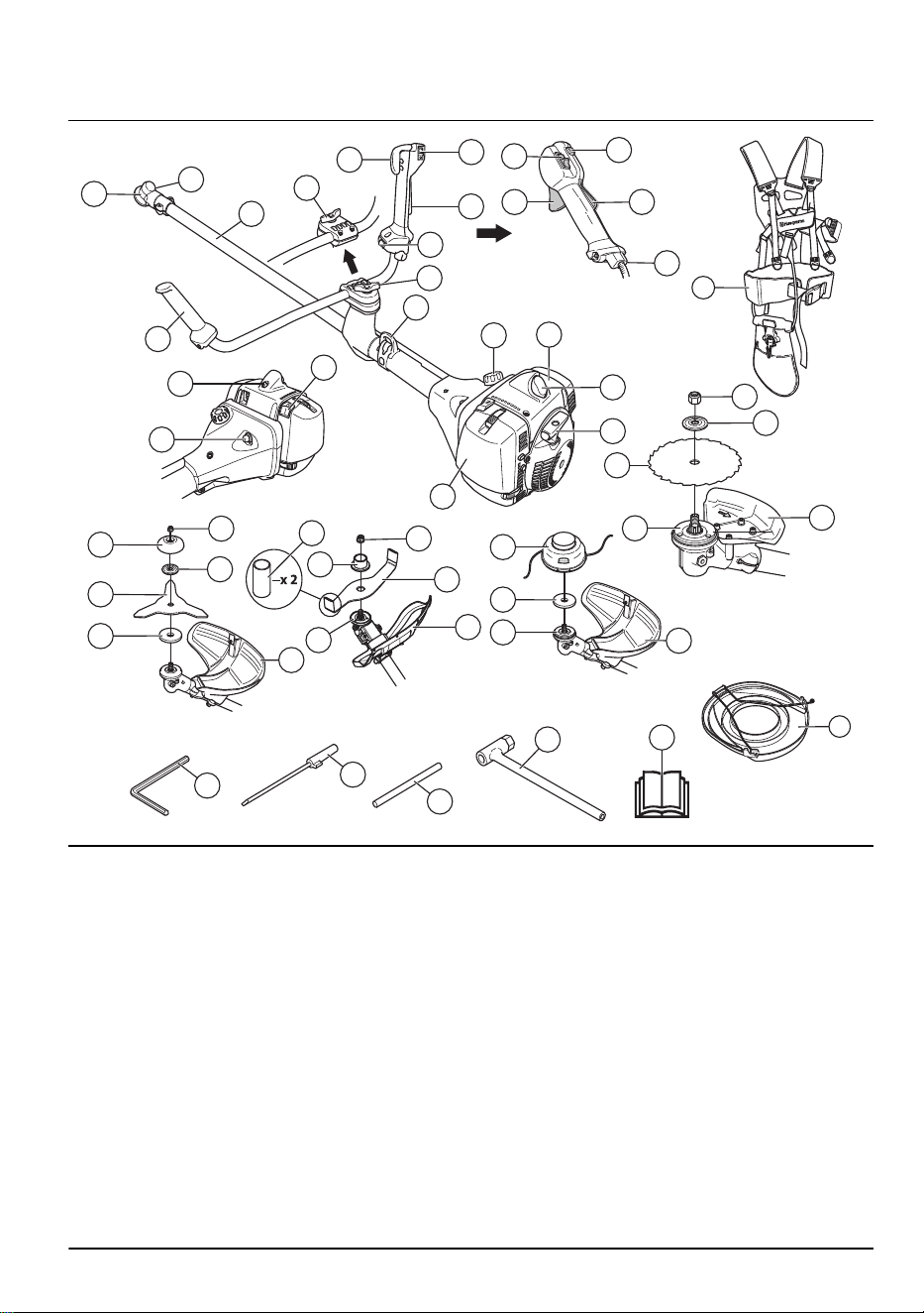
Product overview
4
7
8
9
6
1
2
3
11
10
13
12
14
15
16
17
18
19
20
48
24
23
22
21
39
38
37
35
36
40
52
51
50
49
25
46
41
42
43
44
45
31
32
33
34
26
27
28
29
30
47
5
1. Bevel gear
2. Grease filler cap
3. Shaft
4. Switch for heated handles (XXXX)
5. Handle adjustment (XXXX)
6. Handle adjustment (524R, XXXX, XXXX)
7. Throttle trigger (524R, XXXX)
8. Stop switch (524R, XXXX)
9. Throttle trigger lockout (524R, XXXX)
10. Stop switch (XXXX, XXXX)
11. Throttle trigger (XXXX, XXXX)
12. Throttle trigger lockout (XXXX, XXXX)
13. Start throttle button (XXXX, XXXX)
14. Throttle wire adjustment (XXXX, XXXX)
15. Suspension point
16. Fuel tank
17. Cylinder cover
18. Spark plug and spark plug cap
19. Starter rope handle
20. Air filter cover
21. Choke control
22. Decompression valve
23. Air purge bulb
24. Handlebar
25. Harness
26. Locknut (524R, XXXX)
27. Support flange (524R, XXXX)
28. Saw blade (524R, XXXX)
29. Drive disc (524R, XXXX)
30. Cutting attachment guard (524R, XXXX)
31. Trimmer head (XXXX)
32. Metal cup (XXXX)
1643 - 001 - 07.04.2021 3

33. Drive disc (XXXX)
34. Cutting attachment guard (XXXX)
35. Locknut (XXXX)
36. Support flange (XXXX)
37. Shredder blade (XXXX)
38. Drive disc (XXXX)
39. Cutting attachment guard (XXXX)
40. Transport guard (XXXX)
41. Locknut (XXXX)
42. Support cup (XXXX)
43. Support flange (XXXX)
44. Grass blade (XXXX)
45. Drive disc (XXXX)
46. Cutting attachment guard (XXXX)
47. Transport guard (524R, XXXX, XXXX)
48. Operator's manual
49. Socket wrench
50. Locking pin
51. Carburetor screwdriver
52. Hex key
Symbols on the product
WARNING! This product is dangerous.
Injury or death can occur to the operator
or bystanders if the product is not used
carefully and correctly. To prevent injury
to the operator or bystanders, read and
obey all safety instructions in the
operator's manual.
Read the operator's manual carefully and
make sure that you understand the
instructions before use.
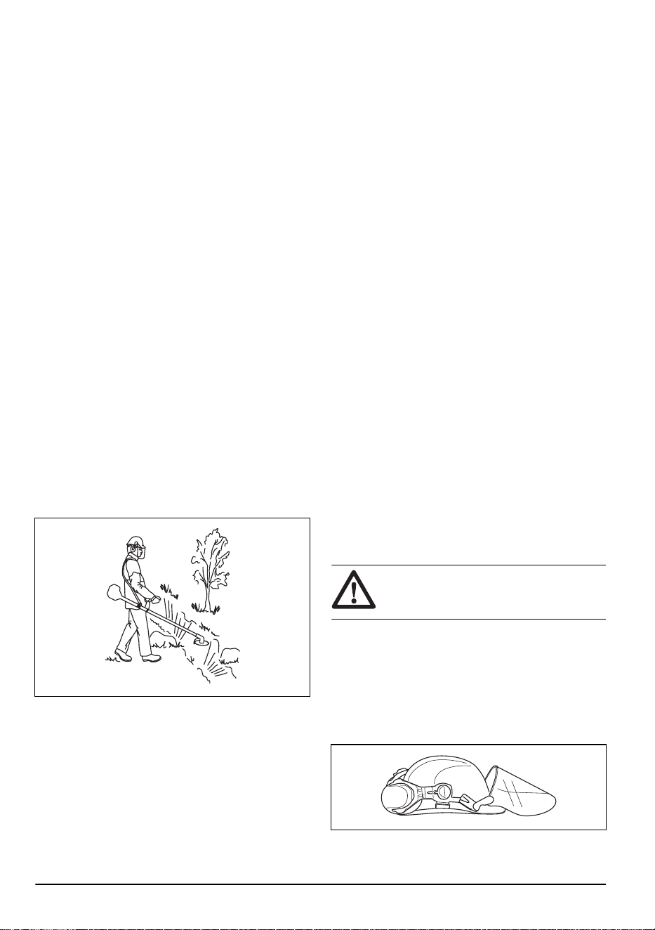
Use a protective helmet in locations where
objects can fall on you. Use approved
hearing protection. Use approved eye
protection.
Use approved protective gloves.
Use heavy-duty slip-resistant boots.
The product can cause objects to eject,
which can cause injury.
Maximum speed of the output shaft.
5
0
FT
1
5
m
50F
T
15 m
Keep a minimum distance of 15 m/50 ft to
persons and animals during operation of
the product.
Risk of blade thrust if the cutting
equipment touches an object that it does
not immediately cut. The product can cut
off body parts. Keep a minimum of 15
m/50 ft distance to persons and animals
during operation of the product.
Only use a flexible cutting wire. Do not
use metal cutting elements. Apply this for
grass guard accessory.
The arrows shows the limit for the handle
position.
Air purge bulb.
Fill fuel.
Choke.
Noise emissions to the environment
according to European Directive
2000/14/EC and New South Wales
legislation "Protection of the Environment
Operations (Noise Control) Regulation
2017". Noise emission data can be found
on the machine label and in
Technical
data on page 28
.
The product agrees with the applicable
EC directives.
yyyywwxxxx The rating plate or the laser printing
shows the serial number. yyyy is the
production year, ww is the production
week.
Note: Other symbols/decals on the product refer to
certification requirements for other commercial areas.
4 1643 - 001 - 07.04.2021

Product liability
As referred to in the product liability laws, we are not
liable for damages that our product causes if:
• the product is incorrectly repaired.
• the product is repaired with parts that are not from
the manufacturer or not approved by the
manufacturer.
• the product has an accessory that is not from the
manufacturer or not approved by the manufacturer.
• the product is not repaired at an approved service
center or by an approved authority.
Euro V Emissions
WARNING: Tampering with the engine
voids the EU type-approval of this product.
Safety
Safety definitions
Warnings, cautions and notes are used to point out
specially important parts of the manual.
WARNING: Used if there is a risk of
injury or death for the operator or bystanders
if the instructions in the manual are not
obeyed.
CAUTION: Used if there is a risk of
damage to the product, other materials or
the adjacent area if the instructions in the
manual are not obeyed.
Note: Used to give more information that is necessary
in a given situation.
General safety instructions
WARNING: Read the warning
instructions that follow before you use the
product.
• This product produces an electromagnetic field
during operation. This field may under some
circumstances interfere with active or passive
medical implants. To reduce the risk of serious or
fatal injury we recommend persons with medical
implants to consult their physician and the medical
implant manufacturer before operating this product.
• Do not use the product if you are tired, ill, or under
the influence of alcohol, drugs or medicine. This has
a negative effect on your vision, alertness,
coordination and judgment.
• Do not operate the product in bad weather, such as
dense fog, heavy rain, strong wind and intense cold.
To operate the product in bad weather can make you
tired and add risks, such as icy ground and
unpredictable felling direction.
• Always be careful and use your common sense. If
you feel uncertain about a work situation or the
operating procedures after you read the operator's
manual, speak to a servicing dealer before you
continue.
• Remove the spark plug cap if you let the product out
of view.
Safety instructions for assembly
WARNING: Read the warning
instructions that follow before you use the
product.
• Use approved protective gloves when you assemble
the product and cutting attachment.
• Remove the spark plug cap from the spark plug
before you assemble the product.
• Make sure that the correct handlebar and cutting
attachment guard are assembled before you operate
the product.
• A defective or incorrect cutting attachment guard can
cause injury. Do not use a cutting attachment without
an approved cutting attachment guard.
• Attach the clutch cover and shaft correctly before
you start the product.
• The drive disc and support flange must engage
correctly in the center hole of the cutting attachment.
A cutting attachment that is attached incorrectly can
cause injury or death.
• Attach the harness to the product to prevent injury to
the operator or others.
Safety instructions for operation
WARNING:
Read the warning
instructions that follow before you use the
product.
• Learn and understand the difference between
forestry clearing, grass clearing and grass trimming
before you use the product.
• Use personal protective equipment, refer to
Personal
protective equipment on page 6
.
• Long-term exposure to noise can result in permanent
hearing loss. Always use approved hearing
protection.
1643 - 001 - 07.04.2021
5
• Listen for warning signals and loud voices when you
use hearing protection. Always remove your hearing
protection when the engine stops.
• Never use the product if it is changed or defective.
• Make sure that the spark plug cap and ignition lead
are not damaged to prevent the risk of electrical
shock.
• Look around the work area to make sure that no
persons, animals or objects have a negative effect
on the safety of the operation of the product.
• Look around the work area to make sure that no
persons or animals touch the cutting attachment or
are hit by objects that are ejected from the cutting
attachment.
• Examine the work area. Remove all loose objects,
such as stones, broken glass, nails, steel wire and
string, that can eject or wind around the cutting
attachment.
• Do not use the product in a situation or location
where you can not get aid if an accident occurs.
• Do not use the product without an approved cutting
attachment guard.
• Make sure that persons or animals keep a distance
of a minimum of 15 m/50 ft during work. Always look
behind you before you turn around with the product.
Stop the product immediately if a person or animal
enters the 15 m/50 ft safety zone. If more than 1
operator does work in the same area, keep a safety
distance of a minimum of 2 times the tree height and
a minimum of 15 m/50 ft.
• Make sure that you can move safely and have a safe
stance. Examine the area around you for obstacles
such as roots, rocks, branch and ditches. Be careful
during work on slopes.
• Do not overreach. Keep a stable position of the feet
and a good balance at all times.
• Before you start the product, put it on a flat surface,
at a minimum ot 3 m/10 ft from the fuel source and
from where you fill fuel. Make sure that there are no
objects near or touching the cutting attachment.
• If the cutting attachment rotates at idle speed, let a
service agent adjust it. Do not use the product until it
is adjusted or repaired.
• Look out for thrown objects. Always use approved
eye protection and keep away from the cutting
attachment guard. Stones and other small objects
can eject into your eyes and cause blindness or
other injuries.
• Do not put the product down with the engine on
unless you have it in clear view.
• Do not remove the cut material, or let other persons
remove cut material, while the engine is on or the
cutting equipment rotates, as this can result in
serious injury.
• Always stop the engine and make sure that the
cutting equipment does not rotate before you remove
material that is wound around the blade shaft or
caught between the cutting attachment guard and
the cutting attachment.
• Be careful when you remove material from around
the cutting equipment. The bevel gear gets hot
during operation and can cause burn injuries.
• The exhaust fumes from the engine are hot and can
contain sparks. Risk of fire. Be careful around dry
and flammable material.
• Never use the product indoors or in spaces lacking
proper ventilation. Exhaust fumes contain carbon
monoxide, an odourless, poisonous and highly
dangerous gas.
• Stop the engine before you move to a new work
area. Always attach the transport guard before you
move the equipment.
• Overexposure to vibration can lead to circulatory
damage or nerve damage in persons who have poor
circulation. Speak to your physician if you
experience symptoms of overexposure to vibration.
Such symptoms include numbness, loss of feeling,
tingling, pricking, pain, loss of strength, changes in
skin colour or condition. These symptoms usually
show in the fingers, hands or wrists. The risk
increases at low temperatures.
Personal protective equipment
WARNING:
Read the warning
instructions that follow before you use the
product.
• Always use approved personal protective equipment
when you use the product. Personal protective
equipment cannot fully prevent injury but it
decreases the degree of injury if an accident does
occur. Let your dealer help you select the correct
equipment.
• Use a helmet if the trees in the work area have a
height of more than 2 m/6.5 ft.
6
1643 - 001 - 07.04.2021
• Use approved hearing protection.
• Use approved eye protection. If you use a visor, you
must also use approved protective goggles.
Approved protective goggles must comply with the
ANSI Z87.1 standard in the USA or EN 166 in EU
countries.
• Use gloves when it is necessary, for example when
you attach, examine or clean the cutting equipment.
• Use protective boots with steel toe-cap and non-slip
soles.
• Use clothing made of a strong fabric. Always use
heavy, long pants and long sleeves. Do not use
loose clothing that can catch on twigs and branches.
Do not use jewelry, short pants or sandals. Do not
go with bare feet. Put your hair up safely above
shoulder level.
• Keep first aid equipment near.
Safety devices on the product
For information about where to find the safety devices,
see
Product overview on page 3
.
WARNING: Read the warning
instructions that follow before you use the
product.
• Do not use a product with defective safety devices.
Do a check of and do maintenance on the safety
devices regularly. If the safety devices are defective,
speak to your Husqvarna service agent.
• Do not make changes to safety devices. Do not use
the product if protective covers, safety switches or
other protective devices are not attached or are
defective.
• For all service and repair work on the product,
especially for the safety devices, special training is
necessary. If the safety devices fail the checks given
in this operator's manual, you must let a service
agent help you. We guarantee that professional
repairs and service is available. If your dealer is not
a service agent, speak to them for information about
the nearest service agent.
• Do not use a cutting attachment without an approved
and correctly attached cutting attachment guard. See
To assemble the cutting equipment on page 12
.
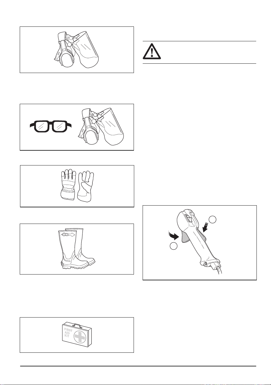
To do a check of the throttle trigger lockout
1. Make sure that the throttle trigger lockout (A) and
throttle trigger (B) move freely and that the return
spring operates correctly.
A
B
1643 - 001 - 07.04.2021
7
2. Push down the throttle trigger lockout and make sure
that it goes back to its initial position when you
release it.
3. Make sure that the throttle trigger is locked at the
idle position when the throttle trigger lockout is
released.
4. Start the product and apply full throttle.
5. Release the throttle trigger and make sure that the
cutting attachment stops and stays stationary.
WARNING:
If the cutting
attachment moves when the throttle
trigger is in the idle position, then the
carburetor idle speed must be adjusted.
Refer to
To adjust the idle speed on
page 22
.
To do a check of the stop switch
1. Start the engine.
2. Move the stop switch to the stop position and make
sure that the engine stops.
To do a check of the cutting attachment guard
WARNING: Do not use a cutting
attachment without an approved and
correctly attached cutting attachment guard.
See
Accessories on page 29
.
WARNING: Always use the
recommended cutting attachment guard for
the cutting attachment that you use. If an
incorrect or faulty cutting attachment guard
is fitted this can cause serious personal
injury. See intructions under heading
Technical data on page 28
.
The cutting attachment guard prevents injuries from
objects that eject in the direction of the operator. It also
prevents injuries that occur if you touch the cutting
attachment.
1. Make sure that the cutting attachment guard is not
damaged or cracked.
2. Replace the guard if it has been exposed to impact
or is cracked.
To do a check of the vibration damping system
The vibration damping system decreases vibration in the
handles to a minimum which makes the operation
easier.
1. Stop the engine.
8
1643 - 001 - 07.04.2021
2. Do a visual check for deformation and damage for
example, cracks.
3. Make sure you attach the elements of the vibration
damping system are correctly.
To do a check of the safety-release mechanism
WARNING: Do not use a harness with
a defective safety-release mechanism.
The safety-release mechanism lets the operator remove
the product quickly from the harness if there is an
emergency.
1. Stop the engine.
2. Do a visual check for damages, such as cracks.
3. Release and attach the safety-release mechanism to
make sure that it operates correctly.
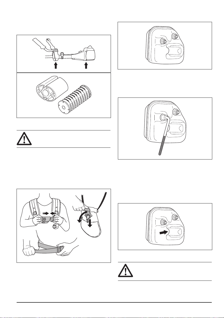
To do a check of the muffler
The muffler keeps noise levels to a minimum and sends
exhaust fumes away from the operator.
• Do a visual check for damage and deformation.
• Make sure that the muffler is correctly attached to
the product.
• If the muffler on your product has a spark arrester
screen, do a visual check. Replace the spark
arrester screen if it is damaged.
a) Clean the spark arrester screen if it is blocked. A
blocked spark arrester screen causes the engine
to become too hot which causes damage to the
engine.
b) Make sure that the spark arrestor mesh is
attached correctly.
To do a check of the locknut
WARNING:
Stop the engine, use
protective gloves and be careful around the
sharp edges of the cutting attachment.
1643 - 001 - 07.04.2021 9
• Make sure that the locknut is attached and tightened
correctly. Refer to
To attach and remove the locknut
on page 25
.
Cutting attachment
WARNING: Read the warning
instructions that follow before you use the
product.
• Do the regular maintenance. Let an approved
service center regularly examine the cutting
attachment to do adjustments or repairs.
• The performance of the cutting attachment
increases.
• The life of the cutting attachment increases.
• The risk of accidents decreases.
• Only use an approved cutting attachment guard.
Refer to
Accessories on page 29
.
• Do not use a damaged cutting attachment.
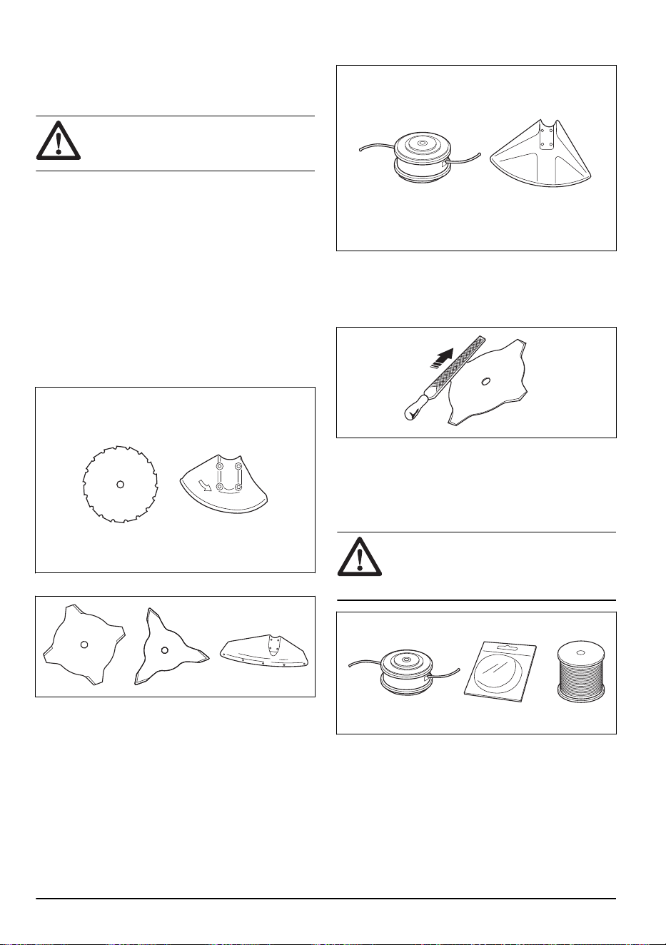
Cutting equipment
• Use the saw blade to cut fibrous types of wood.
• Use the blades and grass knives to cut coarse grass.
• Use the trimmer head to cut grass.
• An incorrectly sharpened or damaged blade
increases the risk of accidents. Keep the teeth of the
blade correctly sharpened. Obey the instructions in
To sharpen the grass knife and grass blade on page
26
and use the recommended file gauge.
• Examine the cutting attachment for damage and
cracks. Replace the damaged cutting attachment.
• Only use cutting attachments with recommended
guards. Refer to
Accessories on page 29
.
Trimmer head
WARNING:
Always make sure the
trimmer line is wound tightly and evenly
around the drum to prevent harmful
vibration.
• Only use recommended trimmer heads and trimmer
lines.
• Only use recommended cutting attachments.
• Smaller machines requires small trimmer heads and
vice versa.
• The length of the trimmer line is important. A longer
trimmer line requires greater engine power than a
shorter trimmer line of the same diameter.
10
1643 - 001 - 07.04.2021

• Make sure that the cutter on the trimmer guard is
intact. This cuts the trimmer line to the correct
length.
• Soak the trimmer line in water for a couple of days
before use to increase the life length.
Saw blade and grass blade
• Use correctly sharpened blades. An incorrectly
sharpened or damaged blade increases the risk of
injury.
• Use correctly set blades. Correct blade set is 1 mm.
An incorrectly set blade increases the risk of injury
and damage.
• To sharpen and set the blade correctly, refer to the
instructions that come with the blade.
Fuel Safety
WARNING: Read the warning
instructions that follow before you use the
product.
• Never start the product if you spill fuel on it. Wipe the
spillage of and allow remaining fuel to evaporate.
• Never start the product if you spill fuel on yourself or
your clothes. Change your clothes and wash any
part of your body that has come in contact with fuel.
Use soap and water.
• Never start the product if the product is leaking fuel.
Check regularly for leaks from the fuel cap and fuel
lines.
• Always put the product on a flat surface and make
sure the cutting attachment cannot come in contact
with any object while you add fuel.
• Take care when handling fuel. Bear in mind the risk
off fire, explosion and inhaling fumes.
• Observe caution when handling fuel and make sure
there is adequate ventilation. Fuel and fuel fumes
are highly inflammable and can cause serious injury
when inhaled or allowed to come in contact with the
skin.
• Mix and pour fuel outdoors, where there are no
sparks or flames.
• Do not smoke or place hot objects near fuel.
• Always stop the engine and let it cool off for a few
minutes before you refuel.
• Open the fuel cap slowly so that any excess
pressure is released gently when you refuel.
• Tighten the fuel cap carefully after you refueled.
• Clean the area around the fuel cap. Contamination in
the tank can cause operating problems.
• Always move the product 3m (10ft) or further from
the refuelling area and source before starting.
Safety instructions for maintenance
WARNING: Read the warning
instructions that follow before you use the
product.
• Stop the engine, make sure that the cutting
attachment stops and let the product cool down
before you do the maintenance.
• Disconnect the spark plug cap before you do the
maintenance.
• The exhaust fumes from the engine contain carbon
monoxide, an odorless, poisonous and very
dangerous gas that can cause death. Do not run the
product indoors or in closed spaces.
• The exhaust fumes from the engine are hot and can
contain sparks. Do not run the product indoors or
near flammable material.
• Accessories and changes to the product that are not
approved by the manufacturer, can cause serious
injury or death. Do not change the product. Always
use original accessories.
• If the maintenance is not done correctly and
regularly, there is an increased risk of injury and
damage to the product.
• Only do the maintenance as this operator's manual
recommends. Let an approved Husqvarna service
agent do all other servicing.
• Let an approved Husqvarna service agent do
servicing on the product regularly.
• Replace damaged, worn or broken parts.
Assembly
Introduction
WARNING: Before you assemble the
product, you must read and understand the
safety chapter.
WARNING: Remove the spark plug
cable from the spark plug before you
assemble the product.
1643 - 001 - 07.04.2021 11
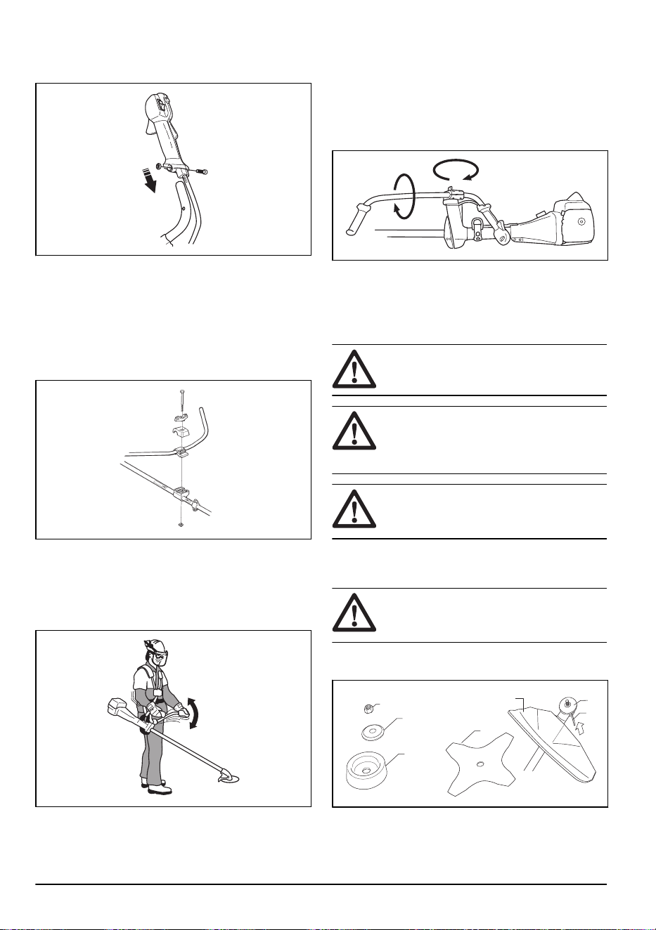
To assemble the handlebar
1. Remove the screw behind the throttle handle.
2. Move the throttle handle to the right side of the
handlebar.
3. Align the hole behind the throttle handle with the
hole in the handlebar.
4. Put the screw go through the holes. Tighten the
screw.
5. Attach the handlebar between the arrows on the
shaft. Tighten the screw.
To install the harness
1. Put on the harness and hang the product from the
suspension point.
2. Adjust the handle to put the product in a good work
position.
3. Tighten the screws fully.
To set the handlebar in transport
position
1. Loosen the knob.
2. Turn the handlebar clockwise until the throttle handle
touches the battery.
3. Turn the handlebar around the shaft.
4. Tighten the knob.
To assemble the cutting equipment
The cutting equipment includes a cutting attachment and
a cutting attachment guard.
WARNING: Use protective gloves.
WARNING: Always use the cutting
attachment guard that is recommended for
the cutting attachment. See
Accessories on
page 29
.
WARNING: An incorrectly attached
cutting attachment can result in injury or
death.
To install a blade guard, grass blade and
grass cutter
CAUTION:
Only use the approved
guard for the blades. See
Accessories on
page 29
.
1. Attach the blade guard/cutting attachment guard (A)
onto the shaft and tighten with the bolt.
E
A
B
C
D
F
G
2. Install the drive disc (B) on the output shaft.
12
1643 - 001 - 07.04.2021
3. Turn the output shaft until one of the holes in the
drive disc aligns with the related hole in the gear
housing.
4. Put the hex key (C) in the hole to lock the shaft.
5. Put the blade (D), support cup (E) and support
flange (F) on the output shaft.
6. Install the nut (G). Torque the nut to 35-50 Nm
(26-36 ft/lb). Hold the shaft of the wrench near the
blade guard as much as possible. To tighten the nut,
you must turn the wrench in the opposite direction of
rotation.
Note: Left hand thread.
To install the blade guard
CAUTION: Only use the approved
guard for the blades. Refer to
Accessories on
page 29
.
1. Remove the bracket (H).
2. Attach the adapter (I) and bracket (J) with the 2
screws (K).
3. Attach the blade guard (A) to the adapter with the 4
screws (L).
J K
I
L
A
H
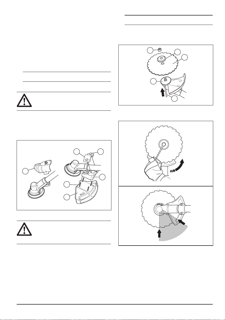
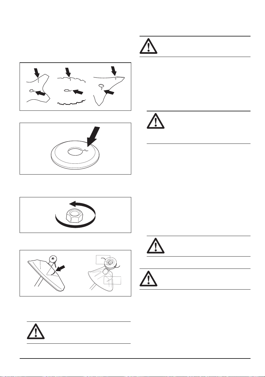
To install the saw blade
WARNING:
There is a risk of injury
around the saw blade nut. Make sure that
the blade guard is correctly installed. Always
use protective gloves.
1. Attach the drive disc (B) to the output shaft.
2. Turn the blade shaft until one of the holes in the
drive disc aligns with the hole in the gear housing.
3. Put the locking pin (C) in the hole to lock the shaft.
4. Install the saw blade (D) and the support flange (F)
to the output shaft.
5. Install the saw blade nut (G).
Note:
The saw blade nut has a left hand thread.
6. Turn the socket wrench counterclockwise to tighten
the locknut. Make sure that the torque of the locknut
is 35-50 Nm (3.5-5 kpm). Hold the shaft of the socket
wrench as near the blade guard as possible.
G
F
D
B
C
a) Make sure that you operate the socket wrench in
the identified area when you loosen or tighten the
saw blade nut.
To assemble the cutting attachment guard and
trimmer head
1. Attach the correct cutting attachment guard (A) for
the trimmer head. Refer to
Accessories on page 29
.
2. Put the cutting attachment guard onto the fitting on
the shaft.
1643 - 001 - 07.04.2021
13
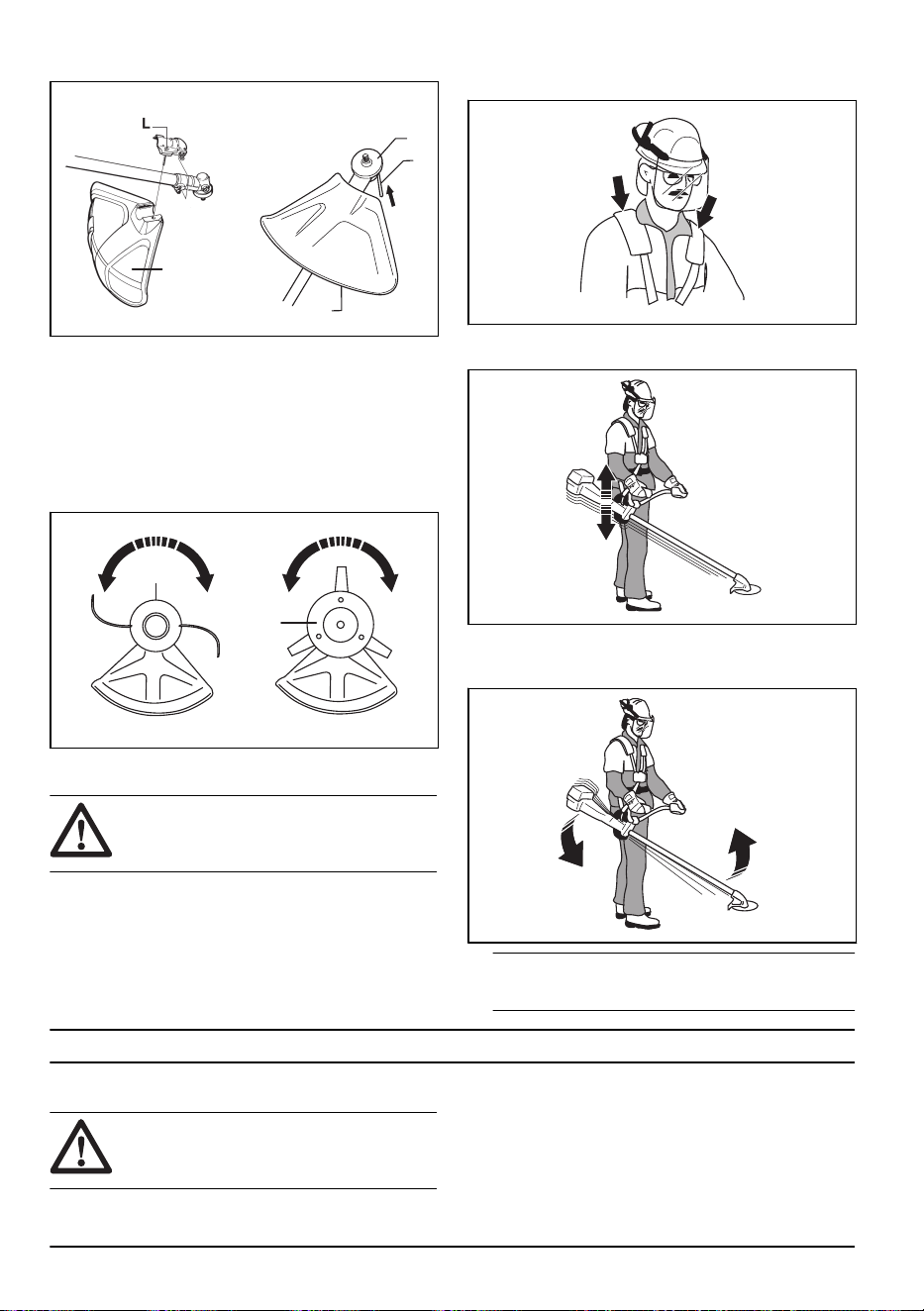
3. Attach with the bolt (L).
A
A
B
C
4. Install the drive disc (B) on the output shaft.
5. Turn the output shaft until one of the holes in the
drive disc aligns with the related hole in the gear
housing.
6. Put the locking pin (C) in the hole to lock the shaft.
7. Turn the trimmer head /plastic blades (H) in the
opposite direction from which the trimmer head/
plastic blades rotates.
H
H
To adjust the harness
WARNING:
The product must always
be correctly attached to the harness. Do not
use a defective harness.
1. Put on the harness.
2. Connect the product to the harness.
3. Adjust the harness for the best work position.
4. Adjust the side straps to make the product weigh
equally on your shoulders.
5. Adjust the harness until the cutting attachment is
parallel to the ground.
6. Let the cutting attachment lightly touch the ground.
Adjust the harness clamp to balance the product
correctly.
Note:
If you use a grass blade, it must balance
approximately 10 cm /4 in above the ground.
Operation
Introduction
WARNING: Before you operate the
product, you must read and understand the
safety chapter.
To do before you operate the product
• Examine the work area to make sure that you know
the type of terrain and the slope of the ground. Look
after if there are obstacles such as stones, branches
and ditches.
• Do an inspection of the product.
14 1643 - 001 - 07.04.2021
• Do maintenance and servicing that are given in this
manual.
• Make sure that all covers, guards, handles and the
cutting equipment are correctly attached and not
damaged.
• Make sure that there are no cracks on the saw blade
or the grass blade . Replace the blade if it is
damaged.
• Examine the support flange for cracks. Replace the
support flange if it is damaged.
• Make sure that the locknut can not be removed by
hand. If you can remove it by hand, it does not lock
the cutting attachment sufficiently and you must
replace it.
• Examine the blade guard for damages or cracks.
Replace the blade guard if it has been hit or if it has
cracks.
• Examine the trimmer head and cutting attachment
guard for damages or cracks. Replace the trimmer
head and cutting attachment guard if they have been
hit or if they have cracks.
WARNING:
Do not use the product
without a guard or a guard that is
defective.
Fuel
This product has a four-stroke engine.
CAUTION: Incorrect type of fuel can
result in engine damage.
Gasoline
• Use Husqvarna 4-stroke fuel for best performance
and extension of the engine life. The Husqvarna 4-
stroke fuel does not become bad or oxidized, which
keeps the maintenance intervals to a minimum.
• If Husqvarna 4-stroke fuel is not available, use good
quality unleaded gasoline with a maximum of 10%
ethanol contents.
CAUTION: Do not use gasoline with
an octane grade less than 90 RON/87
AKI. Use of a lower octane grade can
cause engine knocking, which causes
engine damages.
4-stroke oil
• Do a check of the engine oil level before you start
the product. Too low engine oil level can cause
damage to the engine. Refer to
To do a check of the
engine oil level on page 25
.
• When the product is new, replace the engine oil after
the first month or the first 10 hours of operation.
• Use Husqvarna 4-stroke oil for the best performance
and engine life. Speak to an approved service agent
to select the correct engine oil.
• If Husqvarna 4-stroke oil is not available, use a 4-
stroke oil of good quality with minimum API SG
rating. The recommended viscosity class is SAE
10W-40. Speak to an approved service agent to
select the correct oil.
CAUTION:
Do not use oil for two-
stroke engines.
To fill the fuel tank
WARNING: Obey the procedure that
follows for your safety.
1. Stop the engine and let the engine become cool.
1643 - 001 - 07.04.2021
15
2. Clean the area around the fuel tank cap.
3. Remove the fuel tank cap slowly to release the
pressure.
4. Fill the fuel tank.
CAUTION: Make sure that there is
not too much fuel in the fuel tank. The
fuel expands when it becomes hot.
5. Tighten the fuel tank cap carefully.
6. Clean fuel spillage on and around the product.
7. Move the product 3 m/10 ft or more away from the
refueling area and fuel source before you start the
engine.
Note: To see where the fuel tank is on your product,
refer to
Product overview on page 3
.
Work position
• Hold the product with 2 hands.
• Hold the product on the right side of your body.
• Keep the cutting attachment below waist level.
• Always keep the product attached to the harness.
• Keep body parts away from the hot surfaces.
• Keep body parts away from the cutting attachment.
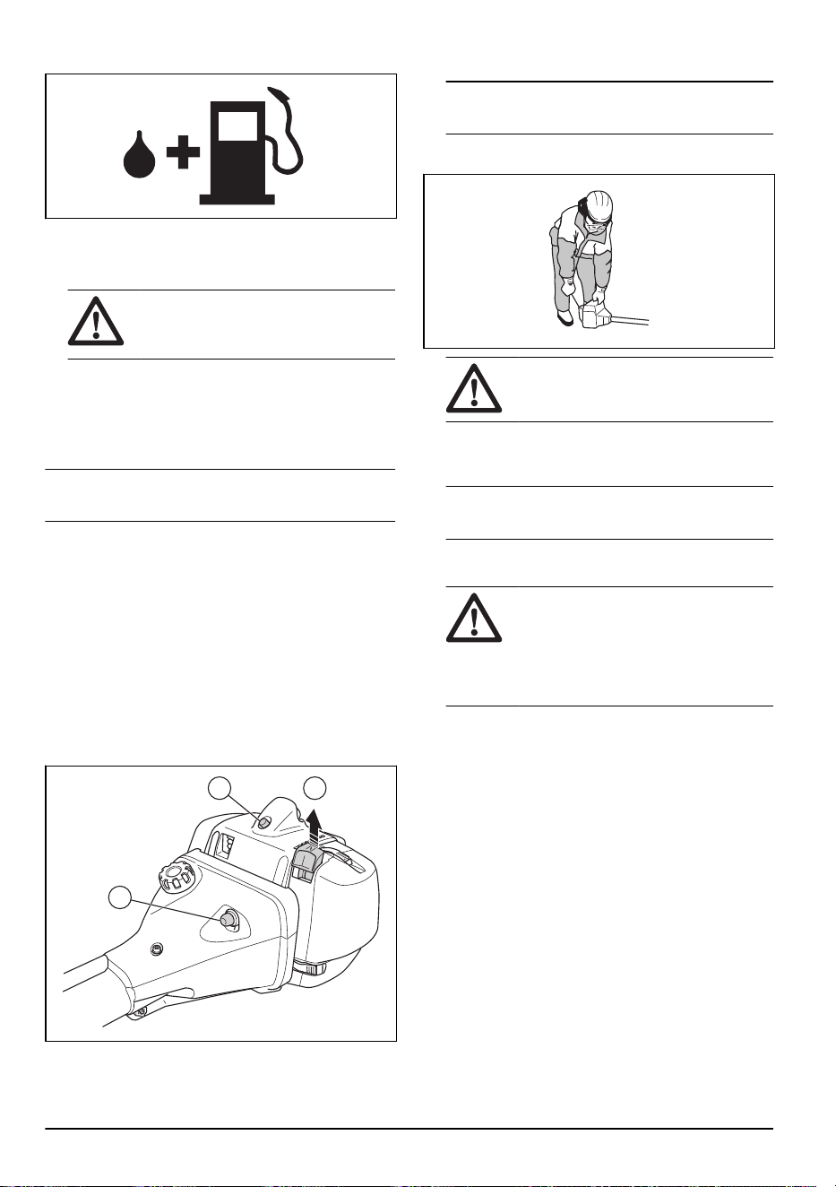
To start a cold engine
1. Set the stop switch to the start position.
2. Set the choke control (A) to the choke position.
C A
B
3. Push the air purge bulb (B) approximately 6 times
until fuel starts to fill the bulb. It is not necessary to
fill the air purge bulb fully.
4. Push the decompression valve (C).
Note: The decompression valve moves to the
initial position when the product starts.
5. Hold the body of the product on the ground with your
left hand.
CAUTION: Do not put your feet on
the product.
6. Pull the starter rope handle slowly until you feel
some resistance. When you feel resistance, pull the
starter rope handle quickly and with force.
Note: Do not wind the starter rope around your
hand.
7. Continue to pull the starter rope handle until the
engine starts.
CAUTION: Do not pull the starter
rope to full extension and do not let go of
the starter rope handle. Release the
starter rope slowly. If you do not obey
these instructions, the engine can
become damaged.
8. Set the choke control to the operation position and
apply full throttle.
To start a warm engine
1. Set the stop switch to the start position.
16
1643 - 001 - 07.04.2021
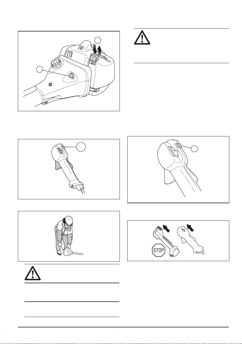
2. Push the air purge bulb (A) approximately 6 times
until fuel starts to fill the bulb. It is not necessary to
fill the air purge bulb fully.
B
A
3. Pull the choke control (B) up and down to set start
throttle.
4. For XXXX, XXXX: To engage the throttle function,
push and release the throttle trigger lockout, the
throttle trigger and the start throttle button (C).
C
5. Hold the body of the product on the ground with your
left hand.
CAUTION:
Do not put your feet on
the product.
6. Pull the starter rope handle slowly until you feel
some resistance. When you feel resistance, pull the
starter rope handle quickly and with force.
Note:
Do not wind the starter rope around your
hand.
7. Continue to pull the starter rope handle until the
engine starts.
CAUTION: Do not pull the starter
rope to full extension and do not let go of
the starter rope handle. Release the
starter rope slowly. If you do not obey
these instructions, the engine can
become damaged.
8. Set the choke control to the operation position and
apply full throttle.
To start with a throttle handle with a
start throttle lock
1. Push the throttle lockout and the throttle trigger to
set the throttle to the start position. Then push the
start throttle button (A).
2. Release the throttle lockout and the throttle trigger,
followed by the start throttle button. The throttle
function is now activated.
3. To return the engine to idle speed, push the throttle
lockout and throttle trigger again.
A
To stop the engine
• Move the stop switch to the stop position.
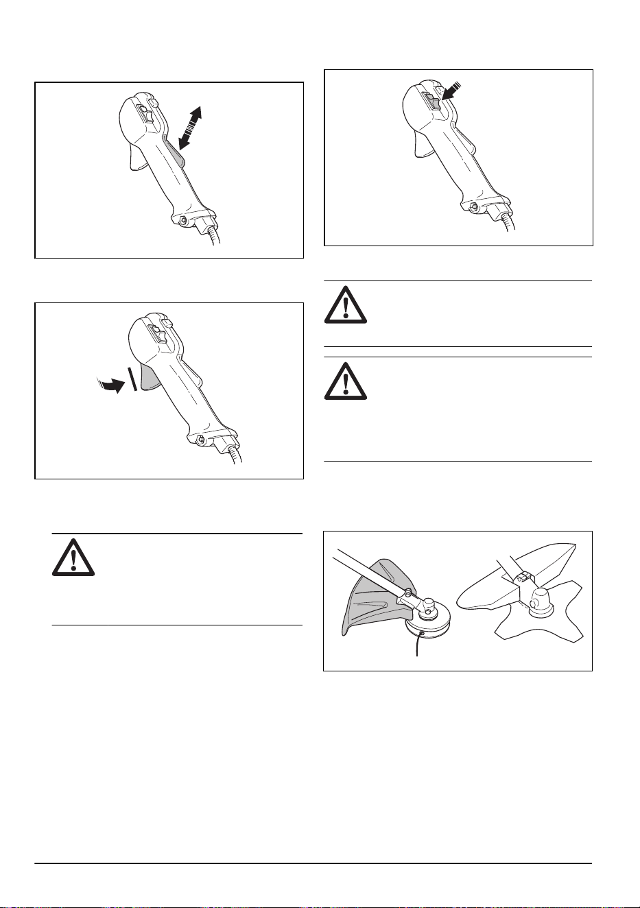
Blade thrust
A blade thrust is when the product moves to the side
quickly and with force. A blade thrust occurs when the
grass blade or saw blade hits or catches on an object
that cannot be cut. A blade thrust can eject the product
1643 - 001 - 07.04.2021
17
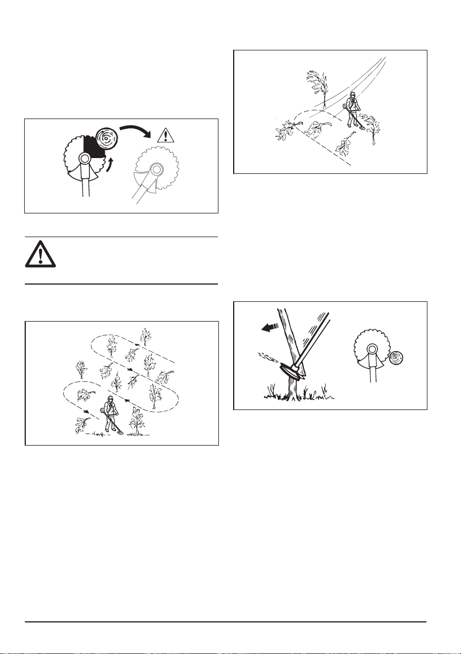
or operator in all directions. There is a risk of injury to
the operator and bystanders.
The risk increases in areas where it is not easy to see
the material that is cut.
Do not cut with the area of the blade that is shown in
black. The speed and movement of the blade can cause
blade thrust. The risk increases with the thickness of the
branch that is cut.
General work instructions
WARNING: Be careful when you cut a
tree that is in tension. It can spring back to
its normal position before or after the cut
and hit you or the product, and cause injury.
• Clear an open space at one end of the work area,
and start the work from there.
• Move in a regular pattern across the work area.
• Move the product fully to the left and right, to clear a
width of 4–5 m on each turn.
• Clear a length of 75 m before you turn and go back.
Move the fuel can along with you as you continue.
• Move in a direction where you do not go across
ditches and obstacles more than necessary.
• Move in a direction where the wind makes the cut
vegetation fall in the cleared area.
• Move along slopes, not up and down.
Forestry clearing with a saw blade
To fell a tree to the left
To fell to the left, push the bottom of the tree to the right.
1. Apply full throttle.
2. Put the saw blade against the tree as given in the
picture.
3. Tilt the saw blade and push it with force diagonally
down to the right. At the same time, push the tree
with the blade guard.
To fell a tree to the right
To fell to the right, push the bottom of the tree to the left.
1. Apply full throttle.
2. Put the saw blade against the tree as given in the
picture.
18
1643 - 001 - 07.04.2021
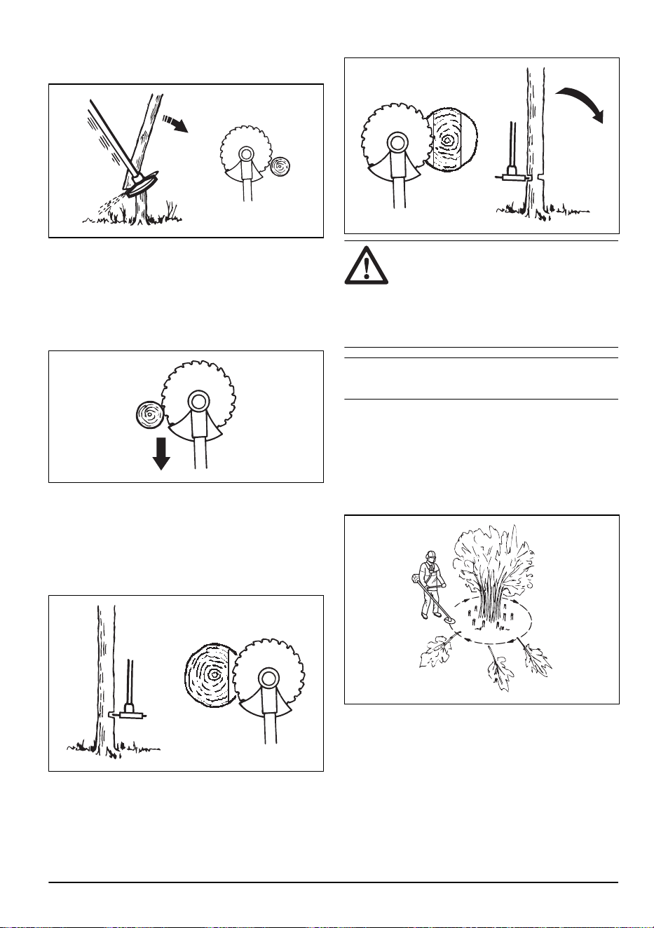
3. Tilt the saw blade and push it with force diagonally
up and to the right. At the same time, push the tree
with the blade guard.
To fell a tree forward
To fell forward, push the bottom of the tree rearward.
1. Apply full throttle.
2. Put the saw blade against the tree as given in the
picture.
3. Pull the saw blade forward with a fast movement.
To fell large trees
Large trees must be cut from 2 sides.
1. Examine in which direction the tree will fall.
2. Apply full throttle.
3. Do the first cut on the side of the tree to which it will
fall.
4. Cut through the tree from the other side.
CAUTION: If the saw blade becomes
blocked, do not pull the product with a
sudden movement. That can cause damage
to the saw blade, bevel gear, shaft or
handlebar. Release the handles, hold the
shaft with 2 hands and carefully pull the
product.
Note: Use more cutting pressure fo fell small trees.
Use less cutting pressure to fell large trees.
Brush cutting with a saw blade
To fell to the left, push the bottom of the tree to the right.
• Cut down thin trees and brush.
• Move the product from side to side.
• Cut many trees in one movement.
• For groups of thin trees:
a) Cut the outer trees high up.
b) Cut the outer trees to the correct height.
c) Cut from the center. If you cannot get access to
the center, cut the outer trees high up and let
them fall. This decreases the risk that the saw
blade becomes blocked.
1643 - 001 - 07.04.2021
19
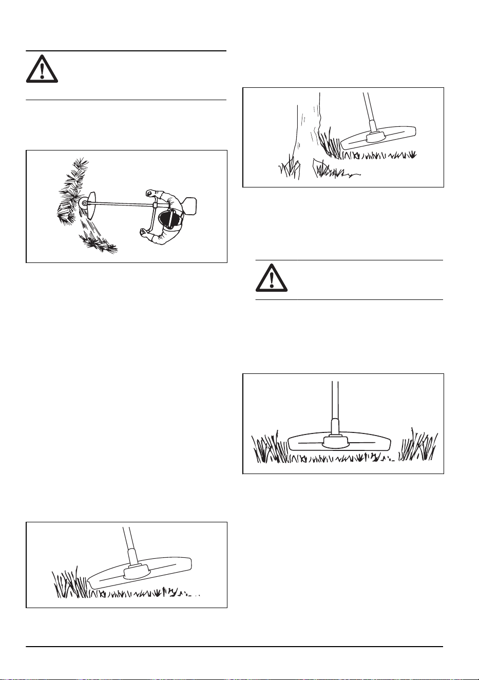
Grass clearing with a grass blade
CAUTION: Do not use grass blades
and grass knives on wood. Use grass
blades and grass knives for long or heavy
grass only.
• Move the product from side to side.
• Start the movement from right to left when you cut.
Move the product to the right before you cut again.
• Cut with the left side of the grass blade.
• Angle the grass blade to the left to make the grass
fall in a line. This makes it easy to collect the grass.
• Keep a stable position with your feet apart.
• Move forward after each right movement and make
sure that you have a stable position again before you
cut again.
• Keep the support cup with a light pressure against
the ground to make sure that the grass blade does
not hit the ground.
• Obey these instructions to decrease the risk that cut
material winds around the grass blade:
a) Apply full throttle.
b) Do not move the grass blade through cut
material when you move the product from left to
right.
• Before you collect the cut material, stop the engine
and remove the product from the harness. Put the
product down on the ground.
Grass trimming with a trimmer head
To trim the grass
1. Hold the trimmer head immediately above the
ground at an angle. Do not push the trimmer line into
the grass.
2. Decrease the length of the trimmer line by 10-12
cm / 4-4.75 in.
3. Decrease the engine speed to decrease the risk of
damage to plants.
4. Use 80 % throttle when you cut grass near objects.
To clear grass
1. Keep the trimmer head above the ground.
2. Tilt the trimmer head.
3. Cut with the end of the trimmer line around objects in
the work area.
CAUTION: Cut grass. Other objects
that are hit by the trimmer line, increases
the wear on the trimmer line.
4. Use 80% speed when you cut and clear vegetation.
This decreases the wear on the trimmer head and
trimmer line.
To cut the grass
1. Make sure that the trimmer line is parallel to the
ground when you cut the grass.
2. Do not push the trimmer head to the ground. This
can cause damage to the product.
20
1643 - 001 - 07.04.2021

3. Move the product from side to side when you cut
grass. Use full speed.
To sweep the grass
The airflow from the rotating trimmer line can be used to
remove cut grass from an area.
1. Hold the trimmer head and the trimmer line parallel
to the ground and above the ground.
2. Apply full throttle.
3. Move the trimmer head from side to side and sweep
the grass.
WARNING: Clean the trimmer head
cover each time you assemble new trimmer
line to prevent unbalance and vibrations in
the handles. Also do a check of the other
parts of the trimmer head and clean it if
necessary.
Maintenance
Introduction
WARNING: Before you do
maintenance, you must read and
understand the safety chapter.
For all servicing and repair work on the product, special
training is necessary. We guarantee the availability of
professional repairs and servicing. If your dealer is not a
service agent, speak to them for information about the
nearest service agent.
Maintenance schedule
Maintenance Daily Weekly Monthly
Clean the external surface. X
Examine the harness for damages. X
Examine the suspension ring for damages. X
Examine the quick-release mechanism on the harness for damages and make
sure that it operates correctly.
X
Do a check of the throttle trigger lockout and the throttle trigger. Refer to
To do a
check of the throttle trigger lockout on page 7
.
X
Make sure that the cutting attachment does not rotate at idle speed. X
Do a check of the stop switch. Refer to
To do a check of the stop switch on page
8
.
X
Examine the cutting attachment guard for damages and cracks. X
Make sure that the saw blade or grass blade is attached correctly. Make sure
that the saw blade or grass blade is sharp and not damaged.
X
Examine the support flange for damages and cracks. Replace it if it is damaged. X
Examine the trimmer head for damages and cracks. Replace it if it is damaged. X
Examine the handle and the handlebar for damages and make sure that they are
attached correctly.
X
Tighten the locknut fully for cutting attachments with a locknut. X
1643 - 001 - 07.04.2021 21

Maintenance Daily Weekly Monthly
Examine the transport guard for damage and make sure that it can be attached
correctly.
X
Examine the engine, the fuel tank and the fuel lines for leaks. X
Clean the air filter. Replace it if it is damaged. X
Do a check of the engine oil level. X
Tighten nuts and screws. X
Examine the starter and the starter rope for damages. X
Examine the vibration damping units for damages and cracks. X
Examine the spark plug. Refer to
To examine the spark plug on page 24
. Re-
place the spark plug if it is necessary. Make sure that the spark plug is fitted with
a suppressor.
X
Clean the cooling system. X
Clean or replace the spark arrester screen. X
Clean the external surface of the carburetor and the area around it. X
Make sure that the bevel gear is filled correctly with grease, see
To lubricate the
bevel gear on page 24
. If not, use Husqvarna bevel gear grease.
X
Examine the fuel filter for contamination and the fuel hose for cracks and other
defects. Replace if it is necessary.
X
Examine all cables and connections. X
Examine the clutch, clutch springs and clutch drum for wear. Replace it if it is
necessary.
X
Replace the spark plug. Make sure that the spark plug is fitted with a suppres-
sor.
X
Clean or replace the spark arrester screen. X
Replace the engine oil. X
To adjust the idle speed
Your Husqvarna product is made to specifications that
decrease harmful emissions.
1. Make sure that the air filter is clean and the air filter
cover is attached before you adjust the idle speed.
2. Adjust the idle speed with the idle speed screw T
which is identified with "T" mark.
a) Turn the idle speed screw T clockwise until the
cutting attachment starts to rotate.
b) Turn the idle speed screw T counterclockwise
until the cutting attachment stops.
22 1643 - 001 - 07.04.2021
WARNING: If the cutting
attachment does not stop when you
adjust the idle speed, speak to your
servicing dealer. Do not use the product
until it is correctly adjusted or repaired.
3. The idle speed is correct when the engine operates
smoothly in all positions. The idle speed must be
below the speed when the cutting attachment starts
to rotate.
Note: Refer to
Technical data on page 28
for the
recommended idle speed.
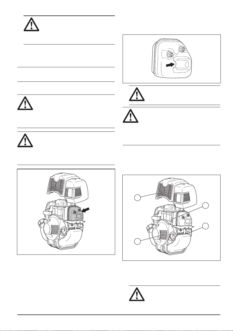
To do maintenance on the muffler
WARNING: The muffler decreases the
noise level and points the exhaust gases
away from the operator. The exhaust gases
are hot and can contain sparks. This can
cause fire if pointed against dry and
flammable material.
WARNING: Mufflers with catalytic
converters become hot during operation.
Risk of burn or fire. This also applies at idle
speed. To examine if your product has a
catalytic converter, refer to
Technical data
on page 28
.
1. Stop the engine and let the muffler become cool.
2. Remove the muffler cover.
3. If the muffler on your product has a spark arrester
screen, do these steps:
a) Do a visual check. Replace the spark arrester
screen if it is damaged.
b) Clean the spark arrester screen if it is blocked.
Clean weekly if your product has a catalytic
converter. Clean monthly if your product does not
have a catalytic converter.
CAUTION: A blocked spark arrester
screen causes the engine to become too
hot which causes damage to the engine.
CAUTION: If the spark arrester screen
is frequently blocked, it can be a sign that
performance of the catalytic converter is
decreased. Speak to your servicing dealer to
examine the muffler. A blocked spark
arrester screen causes overheating and
results in damage to the cylinder and piston.
To clean the cooling system
The parts of the cooling system are the air intake on the
starter (A), the fins on the flywheel (B), the cooling fins
on the cylinder (C) and the cylinder cover (D).
B
C
A
D
1. Clean the cooling system with a brush weekly or
more frequently if it is necessary.
2. Make sure that the cooling system is not dirty or
blocked.
CAUTION:
A dirty or blocked
cooling system can make the product too
1643 - 001 - 07.04.2021 23
hot, which can cause damage to the
product.
To examine the spark plug
CAUTION: Always use the
recommended spark plug type. Incorrect
spark plug type can cause damage to the
product.
• Examine the spark plug if the engine is low on
power, is not easy to start or does not operate
correctly at idle speed.
• To decrease the risk of unwanted material on the
spark plug electrodes, obey these instructions:
a) Make sure that the idle speed is correctly
adjusted.
b) Make sure that the fuel mixture is correct.
c) Make sure that the air filter is clean.
• If the spark plug is dirty, clean it and make sure that
the electrode gap is correct, refer to
Technical data
on page 28
.
• Replace the spark plug if it is necessary.
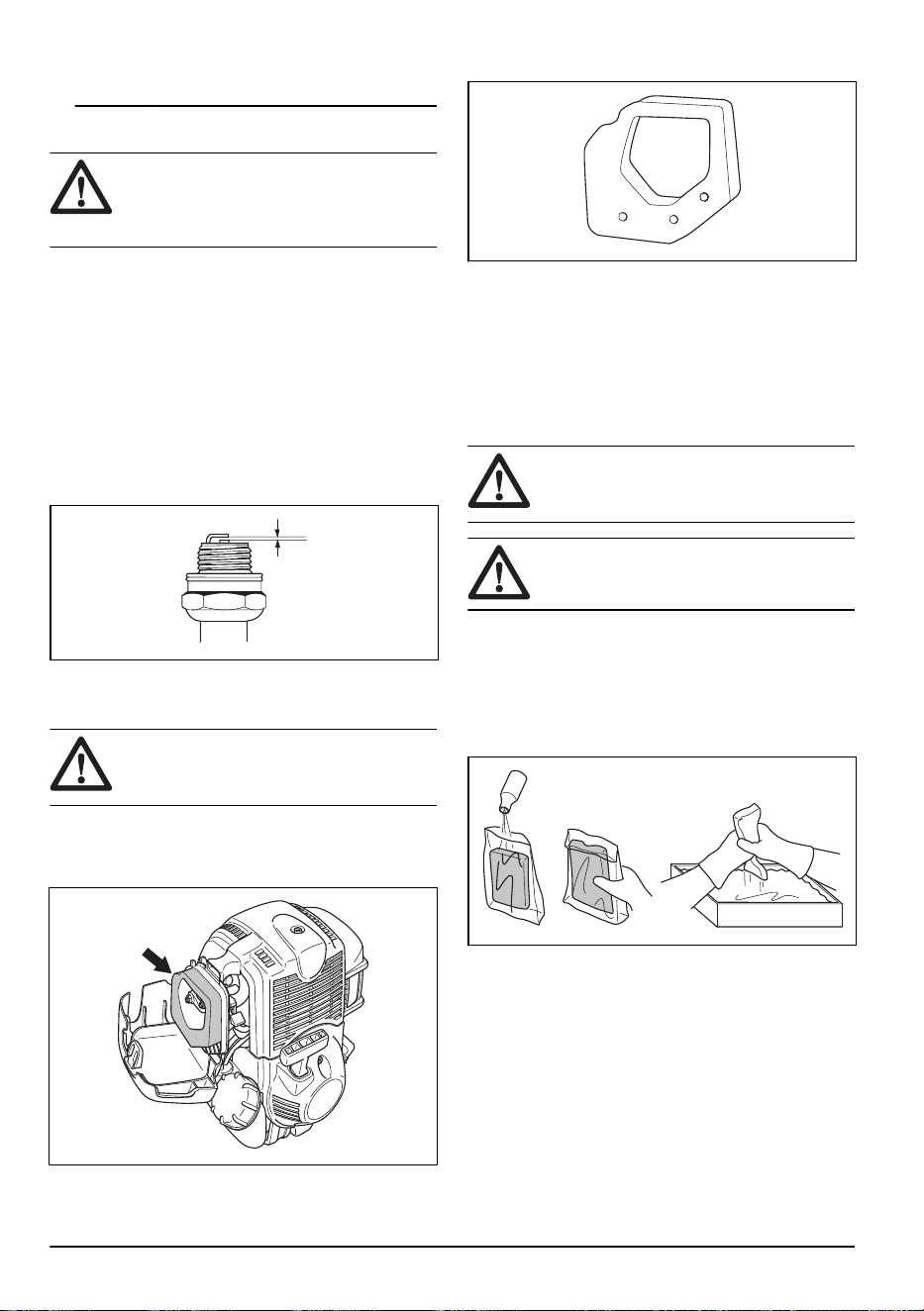
To clean the air filter
CAUTION:
An air filter that is damaged,
very dirty or soaked with fuel must always be
replaced.
An air filter that is used for a long time can not be fully
cleaned. Replace the air filter regularly and always
replace a defective air filter.
1. Move the choke lever up, to close the choke valve.
2. Remove the air filter cover and remove the air filter.
3. Clean the air filter with warm soap water.
4. Clean the inner surface of the air filter cover. Use air
or a brush.
5. Do a check of the surface of the rubber seal.
Replace the filter on the rubber seal if it is damaged.
6. Make sure that the filter is dry before you install it.
To apply oil to the foam air filter
CAUTION: Always use Husqvarna
special air filter oil. Do not use other types of
oil.
WARNING: Put on protective gloves.
The air filter oil can cause skin irritation.
1. Put the foam air filter in a plastic bag.
2. Put the oil in the plastic bag.
3. Rub the plastic bag to supply the oil equally across
the foam air filter.
4. Push the unwanted oil out of the foam air filter while
in the plastic bag.
To lubricate the bevel gear
1. Remove the cutting equipment.
2. Put the product with the grease plug at its highest
position.
24
1643 - 001 - 07.04.2021
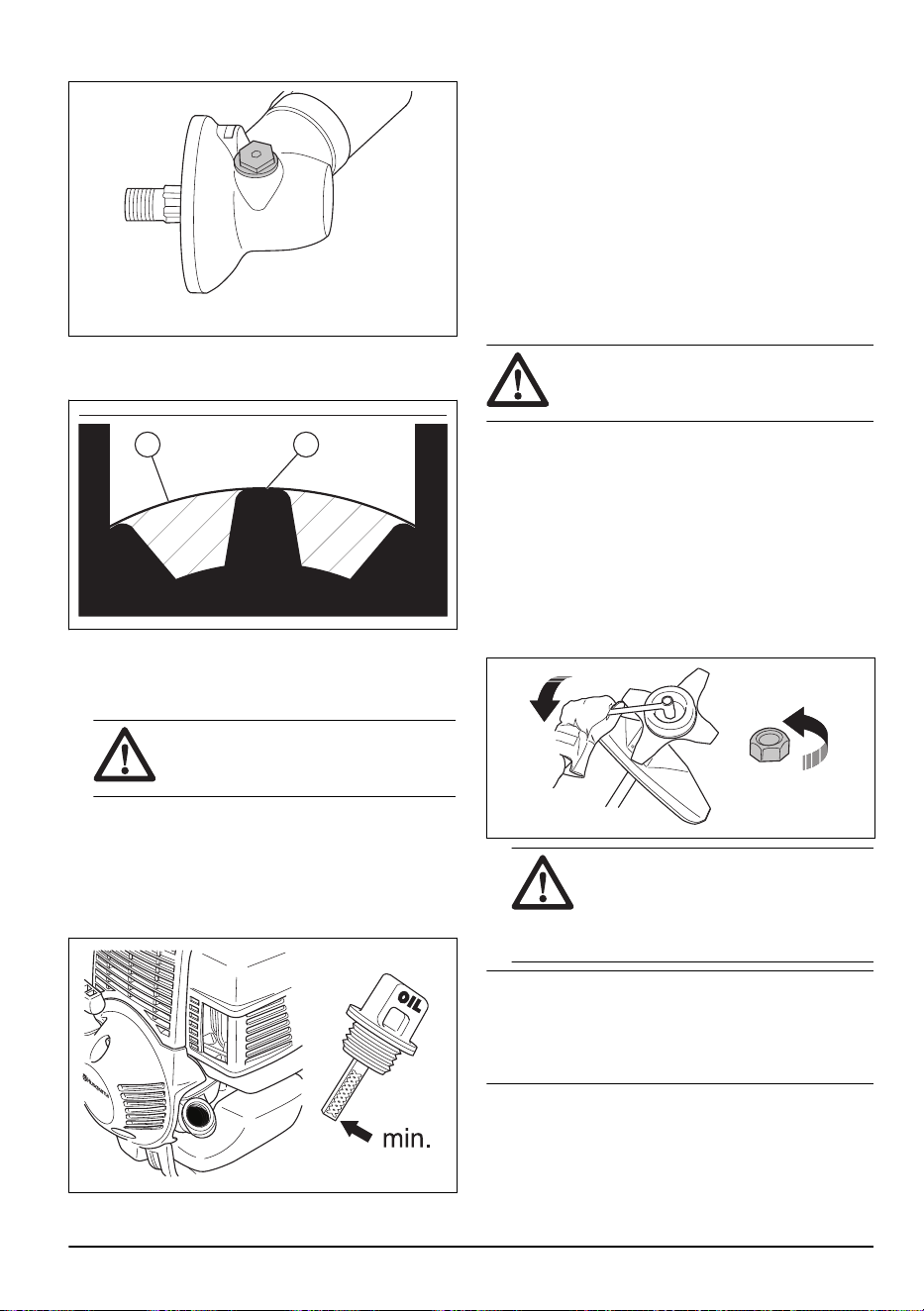
3. Remove the grease plug.
4. Look into the grease plug hole and turn the drive
shaft. The grease level (A) must be in level with the
top of the gear cogs (B).
A B
5. If the grease level is too low fill the bevel gear with
Husqvarna bevel gear grease. Fill slowly and turn
the drive shaft as you apply the bevel gear grease,
stop at the correct level (B).
CAUTION:
An incorrect quantity of
grease can cause damage to the bevel
gear.
6. Install the grease plug.
To do a check of the engine oil level
1. Stop the engine and let the engine become cool.
2. Put the product on level ground.
3. Clean the area around the oil filler cap.
4. Remove the oil filler cap.
5. Remove the oil from the dipstick on the oil filler cap.
6. Put the oil filler cap back into the oil filler neck. Do
not tighten the oil filler cap in this step.
7. Pull out the oil filler cap and read the oil level on the
dipstick.
8. If the oil level is low, fill with engine oil until the oil is
at the edge of the oil filler neck. Only use
recommended engine oil. Refer to
4-stroke oil on
page 15
.
9. Install the oil filler cap and tighten it fully.
To attach and remove the locknut
WARNING: Stop the engine, use
protective gloves and be careful around the
sharp edges of the cutting attachment.
A locknut is used to attach some types of cutting
attachments. The locknut has a left thread.
• To attach, tighten the locknut in the opposite
direction to the direction of turning of the cutting
attachment.
• To remove the locknut, loosen the locknut in the
same direction as the cutting attachment rotates.
• To loosen and tighten the locknut, use a socket
wrench with a long shaft. The arrow in the picture
shows the area where you can operate the socket
wrench.
WARNING:
When you loosen and
tighten the locknut, there is a risk of
injury from the blade. You must always
make sure that the blade guard prevents
injury to your hand when you do this.
Note: Make sure that you can not turn the locknut by
hand. Replace the nut if the nylon lining does not have a
resistance of a minimum of 1.5 Nm. The locknut must be
replaced after it has been put on approximately 10
times.
1643 - 001 - 07.04.2021 25
To sharpen the grass knife and grass
blade
WARNING: Stop the engine. Use
protective gloves.
• To sharpen the grass knife or grass blade correctly,
refer to the instructions that come with the cutting
attachment.
• Sharpen all edges equally to keep the balance.
• Use a single-cut flat file.
WARNING: Always discard a blade
that is damaged. Do not try to make a bent
or twisted blade straight and use it again.
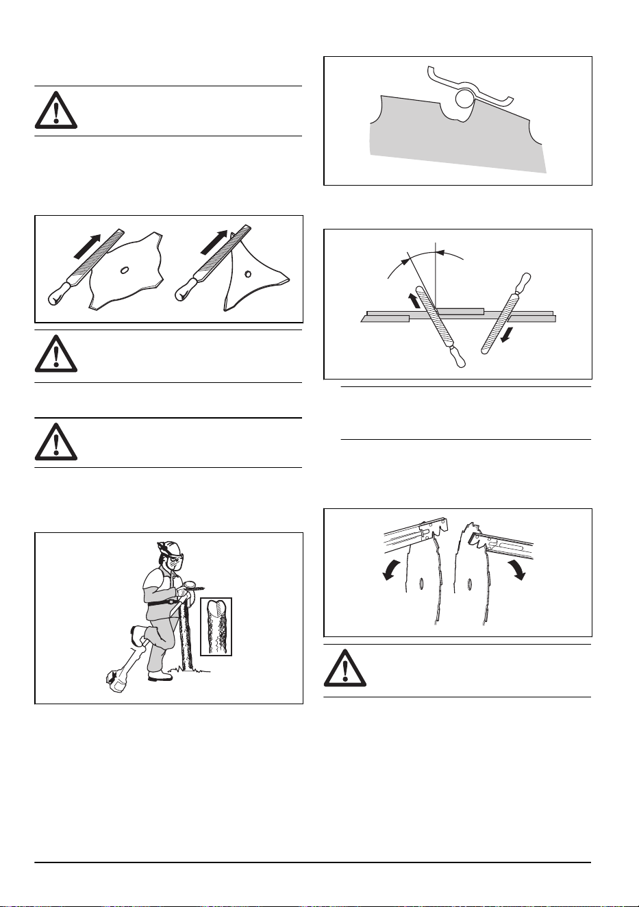
To sharpen the saw blade
WARNING: Stop the engine. Use
protective gloves.
• To sharpen the blade correctly, refer to the
instructions that come with the blade.
• Make sure that the product and blade has sufficient
support when you sharpen it.
• Use a 5.5 mm round file with a file holder.
• Hold the file at an angle of 15°.
• Sharpen one tooth of the saw blade to the right and
the next tooth to the left, see the illustration.
15˚
Note: Sharpen the edges of the teeth with a flat
file if the blade is heavily worn. Continue to sharpen
with a round file.
• Sharpen all edges equally to keep the blade
balanced.
• Adjust the blade set to 1 mm with the recommended
setting tool. Refer to the instructions that come with
the blade.
WARNING:
Always discard a blade
that is damaged. Do not try to make a bent
or twisted blade straight and use it again.
26 1643 - 001 - 07.04.2021

Troubleshooting
The engine does not start
Check Possible cause Procedure
Stop switch. The stop switch is in the stop posi-
tion.
Let an approved servicing dealer re-
place the stop switch.
Starter pawls. The starter pawls cannot move free-
ly.
Remove the starter cover and clean
around the starter pawls. Refer to
To
clean the cooling system on page 23
.
Let an approved servicing dealer
help you.
Fuel tank. Incorrect fuel type. Drain the fuel tank and fill with cor-
rect fuel.
Carburetor Incorrect adjustment of the idle
speed
Adjust the idle speed with the idle
speed screw T.
Spark plug. The spark plug is dirty or wet. Make sure that the spark plug is dry
and clean.
The spark plug electrode gap is in-
correct.
Clean the spark plug. Make sure that
the electrode gap is correct. Make
sure that the spark plug has a su-
pressor.
Refer to
Technical data on page 28
for correct electrode gap.
The spark plug is loose. Tighten the spark plug.
Fuel filter The fuel filter is clogged. Replace the fuel filter.
The engine starts but stops again
Check
Possible cause Procedure
Fuel tank Incorrect fuel type. Empty the fuel tank and fill it with cor-
rect fuel.
Fuel filter The fuel filter is clogged. Replace the fuel filter.
Carburetor The idle speed is not correctly adjus-
ted.
Adjust the idle speed with the idle
speed screw T.
Air filter The air filter is clogged. Clean the air filter.
Transportation and storage
• Always allow the product to cool down before
storage.
• For storage and transportation of the product and
fuel, make sure that there are no leaks or fumes.
1643 - 001 - 07.04.2021 27

Sparks or open flames, for example from electrical
devices or boilers, can start a fire.
• Always use approved containers for storage and
transportation of fuel.
• Empty the fuel before transportation or before long-
term storage. Discard the fuel at an applicable
disposal location.
• Attach the transport guard during transportation and
storage.
• Remove the spark plug cap from the spark plug.
• Attach the product during transportation. Make sure
that it cannot move.
• Clean and do servicing on the product before long-
term storage.
Technical data
Technical data
524R
Engine
Cylinder displacement, cm
3
25
Idle speed, rpm 3100
Maximum engine power acc. to ISO 8893, kW/hp @ rpm 0.8/7000
Catalytic converter muffler No
Speed of output shaft, rpm 8300
Ignition system
Spark plug NGK CMR5H
Electrode gap, mm 0.6
Fuel system and lubrication system
Fuel tank capacity, l/cm
3
0.5/500
Weight
Weight, kg 5.5
Noise emissions
1
Sound power level, measured dB(A) 105
Sound power level, guaranteed L
WA
dB(A) 106
Sound levels
2
Equivalent sound pressure level at the operator's ear, measured according to EN ISO 11806 and ISO 22868, dB(A):
Equipped with trimmer head (original) 93
Equipped with grass blade (original) 89
Vibration levels
3
1
Noise emissions in the environment measured as sound power ( L
WA
) in conformity with EC directive 2000/14/
EC. Reported sound power level for the machine has been measured with the original cutting attachment that
gives the highest level. The difference between guaranteed and measured sound power is that the guaran-
teed sound power also includes dispersion in the measurement result and the variations between different
machines of the same model according to Directive 2000/14/EC.
2
Reported data for equivalent sound pressure level for the product has a typical statistical dispersion (standard
deviation) of 1 dB(A).
3
Reported data for equivalent vibration level has a typical statistical dispersion (standard deviation) of 1 m/s
2
.
28 1643 - 001 - 07.04.2021

524R
Equivalent vibration levels (a
hv,eq
) at handles, measured according to EN ISO 11806 and ISO 22867, m/s
2
:
Equipped with trimmer head (original), left/right 2.9/3.1
Equipped with grass blade (original), left/right 2.7/2.2
Accessories
The accessories used in combination with the specified
power heads have been evaluated to ANSI B175.3-2013
Grass Trimmers and Brushcutters Safety Requirements.
These combinations have been evaluated by
Underwriters Laboratories Inc. (UL) and are
consequently UL listed.
Approved accessories Type Cutting attachment guard, art. no.
Blade shaft thread M10
Plastic blades Tricut Ø 255 mm (separate blades
have part number 531 01 77-15)
588 54037-01/ 58811 79-01
503 93 42-02 / 503 97 71-01
Tricut Ø 300 mm (separate blades
have part number 531 01 77-15)
588 54 37-01
Trimmer head Trimmy Fix (Ø 2.4 mm cord) 588 54 37-01 / 588 11 79-01
503 93 42-02 / 503 97 71-01
Superauto II (Ø 2.4-2.7 mm cord) 588 54 37-01 / 588 11 79-01
503 93 42-02 / 503 97 71-01
S35 (Ø 2.4-3.0 mm cord) 588 54 37-01 / 588 11 79-01
503 93 42-02 / 50397 71-01
T25 (Ø 2.0 - 2.7 mm line) 588 54 37-01 / 588 11 79-01
503 93 42-02 / 503 97 71-01
T35, T35x (Ø 2.4-3.0 mm cord) 588 54 37-01 / 588 11 79-01
503 93 42-02 / 503 97 71-01
Alloy (Ø 2.0-3.3 mm cord) 588 54 37-01 / 588 11 79-01
503 93 42-02 / 503 97 71-01
The accessories are recommended for use in
combination with the specified power heads and have
been evaluated to applicable ISO- and EN safety
requirement standards by the Swedish Machinery
Testing Institute.
Approved attachments Use with
Clean sweep attachment SR600-2 524LK
Hedge trimmer attachment HA110 524LK
1643 - 001 - 07.04.2021 29

Approved attachments Use with
Hedge trimmer attachment HA850 524LK
Edger attachment EA850 524LK
Saw attachment PA1100 524LK
Trimmer attachment TA850 524LK
Extension attachment EX850 524LK
Cultivator attachment CA230 524LK
Blower attachment BA101 524LK
Bristle brush attachment BR600 524LK
Dethatcher attachment DT600 524LK
Brushcutter attachment BCA850-24 524LK
Saw attachment PAX1100 524LK
Saw attachment PAX730 524LK
30 1643 - 001 - 07.04.2021

EC Declaration of Conformity
EC Declaration of Conformity
Husqvarna AB, SE-561 82 Huskvarna, Sweden, tel:
+46-36-146500, declares that the brush cutters
Husqvarna 524R with serial numbers dating from 2016
onwards (the year is clearly stated on the rating plate,
followed by the serial number), comply with the
requirements of the COUNCIL’S DIRECTIVE:
• of May 17, 2006 ”relating to machinery” 2006/42/EC
• of February 26, 2014 ”relating to electromagnetic
compatibility” 2014/30/EU
• of May 8, 2000 ”relating to the noise emissions in the
environment” 2000/14/EC. Conformity assessment
according to Annex V. For information relating to
noise emissions, refer to
Technical data on page 28
.
• of June 8, 2011 ”on the restriction of the use of
certain hazardous substances in electrical and
electronic equipment” 2011/65/EU.
The following standards have been applied:
EN ISO 12100:2010, EN ISO 11806-1:2011, ISO
14982:1998, CISPR 12:2007, EN 50581:2012
RISE SMP Svensk Maskinprovning AB, Box 7035,
SE-750 07 Uppsala, Sweden, has performed voluntary
type examination on behalf of Husqvarna AB. The
certificates are numbered: SEC/09/2176 - 524R, XXXX,
SEC/09/2175 - XXXX, XXXX.
RISE SMP Svensk Maskinprovning AB has also verified
agreement with appendix V of the council’s directive
2000/14/EG. The certificates have the numbers:
01/164/062 - 524R, XXXX, 01/164/070 - XXXX, XXXX.
Huskvarna, 2016-03-30
Per Gustafsson, Development Manager (Authorized
representative for Husqvarna AB and responsible for
technical documentation)
1643 - 001 - 07.04.2021
31

www.husqvarna.com
Original instructions
1158422-26
2021-04-13