User Manual
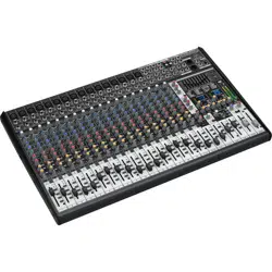
EURODESK SX3242FX/SX2442FX
Ultra-Low Noise Design 32/24-Input 4-Bus
Studio/Live Mixer with XENYX Mic Preampli ers,
British EQs and Dual Multi-FX Processor

2 EURODESK SX3242FX/SX2442FX User Manual
Thank you
Congratulations! With the EURODESK you have acquired a state-of-the-art mixing
console that sets new standards. Right from the very start it has been our goal to
design a revolutionary unit that can be used for a great variety of applications.
And indeed, this overwhelming mixing console gives you plenty of functionality
and a broad range of connection and expansion options.
BEHRINGER is a company with its roots in professional recording studio
technology. For many years now we have been successful in developing products
for studio and live use. These include microphones and studio gear of all kinds
(compressors, enhancers, noise gates, tube processors, headphone ampliers,
digital eects, DI boxes, etc.), monitor and P.A. speakers as well as professional
live and recording mixers. Our entire technical know-how has gone into your
EURODESK mixing console.
Table of Contents
Thank you ....................................................................... 2
Important Safety Instructions ...................................... 3
Legal Disclaimer ............................................................. 3
Limited Warranty ........................................................... 3
1. Introduction ............................................................... 4
1.1 Before you get started ...................................................... 4
1.2 The manual ........................................................................... 4
2. Control Elements and Connections ......................... 5
2.1 Mono input channels ........................................................ 5
2.2 Stereo channels ................................................................... 6
2.3 Stereo channels 21-24 (SX2442FX) or
29-32 (SX3242FX) ........................................................................ 7
2.4 Subgroups 1 - 4 ................................................................... 7
2.5 Mono out section for subwooferapplications ........ 8
2.6 Main out section ................................................................. 8
2.7 CD/Tape ................................................................................. 9
2.8 Master Aux Send 1 and 2 ................................................. 9
2.9 Graphic 9-band stereo equalizer ................................ 10
2.10 Eects section .................................................................. 10
2.11 Rear panel .......................................................................... 11
3. Digital Eects Processor ......................................... 11
4. Wiring Examples ...................................................... 12
4.1 Studio set-up ...................................................................... 12
4.2 Live set-up ........................................................................... 13
5. Audio Connectors .................................................... 13
6. Presets ...................................................................... 15
7. Specications ........................................................... 16
3 EURODESK SX3242FX/SX2442FX User Manual
Important Safety
Instructions
LEGAL DISCLAIMER
LIMITED WARRANTY
Terminals marked with this symbol carry
electrical current of su cient magnitude
to constitute risk of electric shock.
Use only high-quality professional speaker cables with
¼" TS or twist-locking plugs pre-installed. Allother
installation or modi cation should be performed only
by quali edpersonnel.
This symbol, wherever it appears,
alertsyou to the presence of uninsulated
dangerous voltage inside the
enclosure-voltage that may be su cient to constitute a
risk ofshock.
This symbol, wherever it appears,
alertsyou to important operating and
maintenance instructions in the
accompanying literature. Please read the manual.
Caution
To reduce the risk of electric shock, donot
remove the top cover (or the rear section).
No user serviceable parts inside. Refer servicing to
quali ed personnel.
Caution
To reduce the risk of re or electric shock,
do not expose this appliance to rain and
moisture. The apparatus shall not be exposed to dripping
or splashing liquids and no objects lled with liquids,
suchas vases, shall be placed on the apparatus.
Caution
These service instructions are for use
by quali ed service personnel only.
Toreduce the risk of electric shock do not perform any
servicing other than that contained in the operation
instructions. Repairs have to be performed by quali ed
servicepersonnel.
1. Read these instructions.
2. Keep these instructions.
3. Heed all warnings.
4. Follow all instructions.
5. Do not use this apparatus near water.
6. Clean only with dry cloth.
7. Do not block any ventilation openings. Install in
accordance with the manufacturer’s instructions.
8. Do not install near any heat sources such as
radiators, heat registers, stoves, or other apparatus
(including ampli ers) that produce heat.
9. Do not defeat the safety purpose of the polarized
or grounding-type plug. A polarized plug has two blades
with one wider than the other. A grounding-type plug
has two blades and a third grounding prong. The wide
blade or the third prong are provided for your safety. Ifthe
provided plug does not t into your outlet, consult an
electrician for replacement of the obsolete outlet.
10. Protect the power cord from being walked on or
pinched particularly at plugs, convenience receptacles,
and the point where they exit from the apparatus.
11. Use only attachments/accessories speci ed by
themanufacturer.
12. Use only with the
cart, stand, tripod, bracket,
or table speci ed by the
manufacturer, orsold with
the apparatus. When a cart
is used, use caution when
moving the cart/apparatus
combination to avoid
injury from tip-over.
13. Unplug this apparatus during lightning storms or
when unused for long periods of time.
14. Refer all servicing to quali ed service personnel.
Servicing is required when the apparatus has been
damaged in any way, such as power supply cord or plug
is damaged, liquid has been spilled or objects have fallen
into the apparatus, the apparatus has been exposed
to rain or moisture, does not operate normally, or has
beendropped.
15. The apparatus shall be connected to a MAINS socket
outlet with a protective earthing connection.
16. Where the MAINS plug or an appliance coupler is
used as the disconnect device, the disconnect device shall
remain readily operable.
17. Correct disposal of this
product: This symbol indicates
that this product must not be
disposed of with household
waste, according to the WEEE
Directive (2012/19/EU) and
your national law. This product
should be taken to a collection center licensed for the
recycling of waste electrical and electronic equipment
(EEE). The mishandling of this type of waste could have
a possible negative impact on the environment and
human health due to potentially hazardous substances
that are generally associated with EEE. At the same time,
your cooperation in the correct disposal of this product
will contribute to the e cient use of natural resources.
For more information about where you can take your
waste equipment for recycling, please contact your local
city o ce, or your household waste collection service.
MUSIC Group accepts no liability for any loss which
may be su ered by any person who relies either
wholly or in part upon any description, photograph,
or statement contained herein. Technical speci cations,
appearances and other information are subject to
change without notice. All trademarks are the property
of their respective owners. MIDAS, KLARK TEKNIK,
TURBOSOUND, BEHRINGER, BUGERA and DDA are
trademarks or registered trademarks of MUSIC Group IP
Ltd. © MUSIC Group IP Ltd. 2015 All rights reserved.
For the applicable warranty terms and conditions
and additional information regarding MUSIC Group’s
Limited Warranty, please see complete details online at
music-group.com/warranty.

4 EURODESK SX3242FX/SX2442FX User Manual
1. Introduction
FBQ Feedback Detection System
One of the most outstanding features of this console is the
FBQFeedback Detection System, which is part of the graphic
equalizer. This ingenious circuit makes it possible to detect and
subsequently eliminate feedback frequencies very quickly.
FBQincreases the brightness of the EQ fader LEDs for the frequency bands where
feedback is occurring. What used to be a tedious search for feedback frequencies
is now mere child’s play.
XENYX Mic Preamps
The microphone channels feature high-end XENYXMicPreamps
that compare well with costly outboard preamps in terms of sound
quality and dynamics and boast the following features:
t 130 dB dynamic range for an incredible amount of headroom
t A bandwidth ranging from below 10 Hz to over 200kHz for crystal-clear
reproduction of even the nest nuances
t The extremely low-noise and distortion-free circuitry guarantees absolutely
natural and transparent signal reproduction
t They are perfectly matched to every conceivable microphone with up to
60dB gain and +48 volt phantom power supply
t They enable you to use the greatly extended dynamic range of your
24-bit/192-kHz HD recorder to the full, thereby maintaining optimal
audioquality
“British EQ”
The equalizers used for the XENYX Series are based on the legendary circuitry of
top-notch consoles made in Britain, which are renowned throughout the world
for their incredibly warm and musical sound character. Even with extreme gain
settings these equalizers ensure outstanding audio properties.
What is more, the EURODESK comes with two eects processors
using 24-bit A/D and D/A converters and the eects algorithms of
our renowned 19" multi-eects device VIRTUALIZERPRO
DSP2024P. Each processor oers 99presets with rst-class room
simulations, delay and modulation eects as well as compressor, tube distortion
and numerous other eects available—all with excellent audio quality!
The mixer is equipped with a state-of-the-art integrated
switch-mode power supply. Unlike conventional designs,
thissupply automatically adapts to supply voltages between
100and 240 V. With its considerably higher eciency, it is also
more economical in terms of power consumption than standard power supply units.
1.1 Before you get started
1.1.1 Shipment
Your product was carefully packed at the factory to ensure safe transport.
Nevertheless, if the box is damaged inspect the unit immediately for signs
ofdamage.
◊ If the unit is damaged please do NOT return it to us, but notify your
dealer and the shipping company immediately; otherwise, claims for
damage or replacement may not be granted.
◊ We recommend that you use a flight case to give the unit optimum
protection during use or transport.
◊ Always use the original box to prevent damage during storage
or transport.
◊ Make sure that children cannot play unsupervised with the unit or
its packaging.
◊ Please ensure proper disposal of all packing materials.
1.1.2 Initial operation
Ensure adequate air supply and to avoid overheating do not place the unit
nearradiators etc.
◊ Blown fuses must be replaced by fuses of the correct rating!
Please refer to the “Specifications” section for the applicable rating.
For connection to the mains use the enclosed power cord with cold connector
which complies with the relevant safety regulations.
◊ Please make sure that all devices are properly grounded. For your own
safety, never remove or disable the ground conductors from the devices
or on the power cords. The unit must always be connected to the mains
outlet with a protective grounding connection.
◊ We would like to point out that high volume levels may damage your
hearing and/or your headphones/loudspeakers. To avoid switch-on/off
thumps from the console and any downstream devices, always make
sure that your power amp(s) or active speakers are the last components
that are switched on and the first to be switched off. Always make sure
that the appropriate volume is set.
Important notes concerning installation
◊ The sound quality may diminish within the range of powerful
broadcasting stations and high-frequency sources. Increase the
distance between the transmitter and the device and use shielded
cables for all connections.
1.1.3 Online registration
Please register your new BEHRINGER equipment right after your purchase
by visiting http://behringer.com and read the terms and conditions of our
warranty carefully.
Should your BEHRINGER product malfunction, it is our intention to have it
repaired as quickly as possible. To arrange for warranty service, please contact
the BEHRINGER retailer from whom the equipment was purchased. Shouldyour
BEHRINGER dealer not be located in your vicinity, you may directly contact
one of our subsidiaries. Corresponding contact information is included in the
original equipment packaging (Global Contact Information/European Contact
Information). Should your country not be listed, please contact the distributor
nearest you. A list of distributors can be found in the support area of our website
(http://behringer.com).
Registering your purchase and equipment with us helps us process your repair
claims more quickly and eciently.
Thank you for your cooperation!
1.2 The manual
This manual is designed to give you an overview of all control elements and
at the same time inform you in detail about how to use them. To provide you
with a clear structure, we have grouped the control elements according to their
function. They can easily be found on the enclosed numbered illustrations.
Ifyouneed more detailed information on specic topics, please visit our web site
at behringer.com. The product-related information pages and the ULTRANET-
based glossary explain the relevant audio engineering terminology infull detail.
5 EURODESK SX3242FX/SX2442FX User Manual
2. Control Elements and
Connections
This chapter describes the various control elements of your mixing console.
Allcontrols and connections are explained in full detail.
2.1 Mono input channels
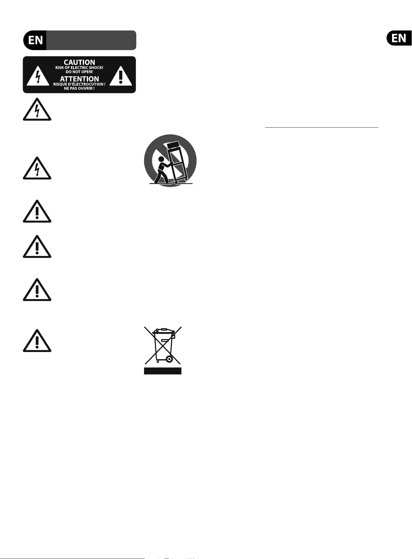
2.1.1 Microphone and line inputs
Fig. 2.1:
(1)
(2)
(3)
(4)
(5)
Connectors and controls of the mic/line inputs
(1) Each mono input channel is equipped with a balanced microphone input
on an XLR connector, which provides +48 V phantom power for condenser
microphones at the touch of a button (see rear panel).
◊ Be sure to switch off your audio system before you activate the
phantom power supply to prevent audible switch-on thumps from
reaching your monitor speakers. Please also note the information given
in chapter 2.11 “Rear panel”.
(2) Each mono input also has a balanced line input on ¼" TRS connectors.
Of course, these inputs can also be used with unbalanced plugs
(¼" TS connector).
(3) The INSERT I/O connector is used to process a signal with dynamic
processors or equalizers. This insert point isprefader, pre-EQ and
pre-aux send.
Unlike reverb and other eects, which are usually added to the dry signal,
dynamic processors process the entire signal. So, aux send buses are not the
best solution here. Instead, dynamic processors and equalizers are inserted
into the signal path. Once processed, the signal then re-enters the mixing
console at the same point where it left. Signal interruption only occurs if
a plug is inserted into the corresponding jack (¼" stereo plug: tip = signal
output, ring = input). All mono input channels are equipped with insert
points. They can also be used as pre-EQ direct outputs, without signal
ow interruption. For this you need a cable with a ¼" TS connector on the
recorder/eects processor end, and a bridged stereo ¼" TRS connector on
the console end (tip and ring interconnected).
(4) The GAIN control adjusts the input gain. Be sure to set this control fully
counter-clockwise before you connect or disconnect a signal source to or
from one of the inputs.
GAIN has a dual scale: the rst scale has a gain from +1 0to +60 dB for
theMIC input.
The second scale has a gain from +1 0 to -40 dBu for the line input.
Fordevices with a nomal line output level of-10 dBV or +4 dBu the setting
is as follows: with GAIN fully counter-clockwise connect the external device
and adjust the output level recommended by the manufacturer. If available,
the output level display of the external device should read 0 dB with signal
peaks. For +4 dBu increase GAIN, for -10 dBV increase it further. The ne-
tuning can be done with a music signal and the LEVEL SET LED, which will
illuminate when the optimum operating level has been set.
(5) Mono channels are equipped with a high-slope LOWCUT lter eliminating
unwanted low-frequency signals, such as oor rumble (18 dB/oct., -3 dB
at 80 Hz).
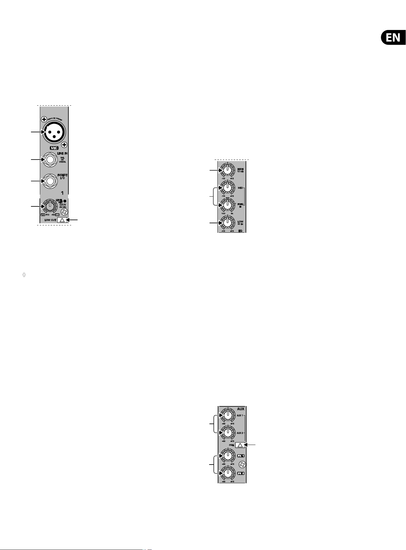
2.1.2 Equalizer
All mono input channels are equipped with a 3-bandequalizer. The maximum
boost/cut of the individual bands is 15 dB, in mid position the EQ is set to neutral.
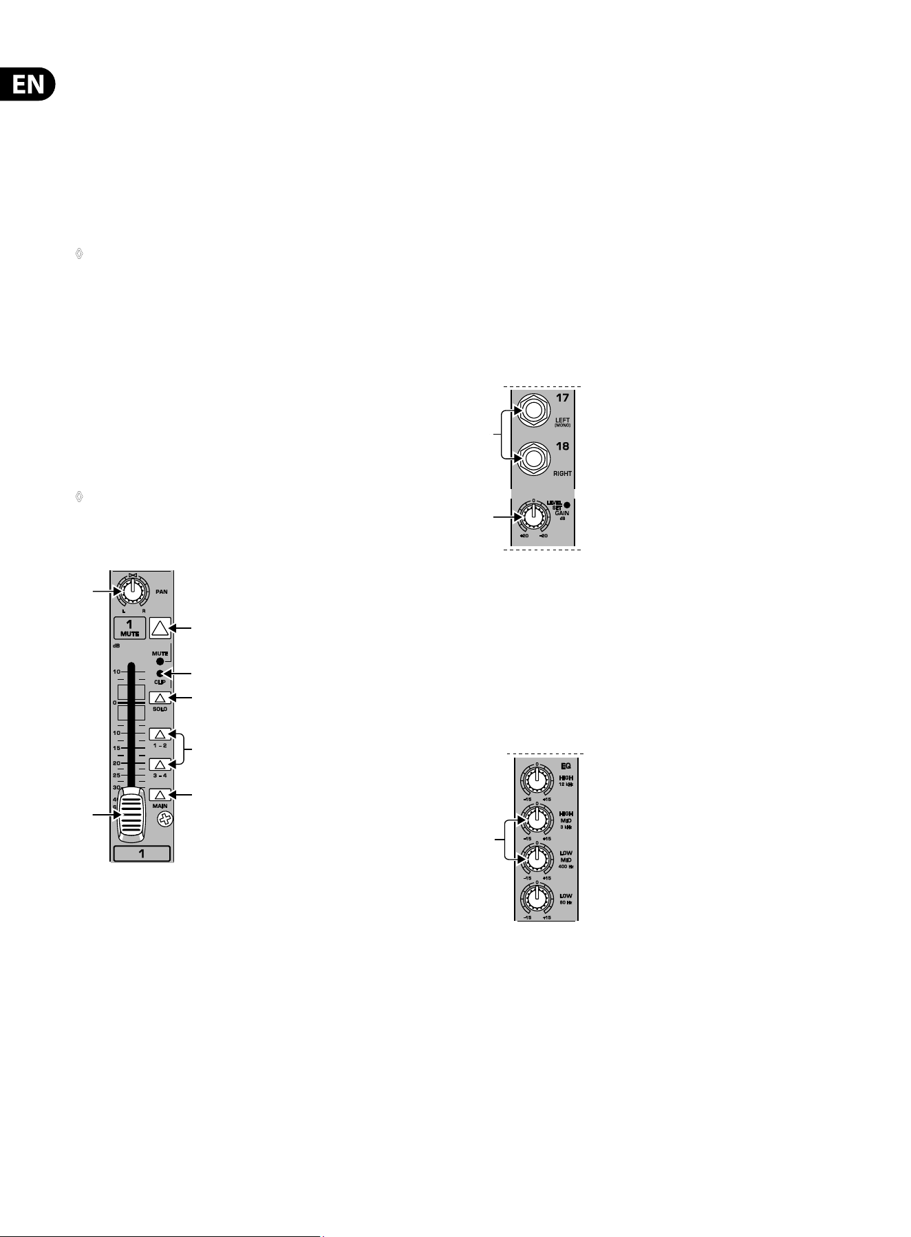
Fig. 2.2:
(6)
(7)
(8)
Equalizer section of input channels
(6) The HIGH control in the EQ section controls the high frequency range of
the respective channel. It is a shelving-type lter which can boost or cut all
frequencies above a xed frequency (12 kHz).
(7) The MID control allows you to raise or lower the mid-range level. It is a semi-
parametric peak lter, which boosts or cuts the frequency range around a
variable mid-range frequency. Use the FREQ control to select the mid-range
frequency from 100 Hz to 8 kHz. Then use the MID control to boost or cut the
selected frequency range.
(8) The LOW control boosts or cuts the low-frequency range. Like the HIGH lter
it is a shelving-type lter, which raises or lowers the level of all frequencies
below a specic frequency (80 Hz).
2.1.3 Aux/FX send buses
Aux sends enable you to take the signals from one or multiple channels and
collect them on one bus. This signal is then present at one of the aux send jacks,
from where it can be routed to an active monitor speaker or external eects
device, for example. The FX returns are subsequently used as a return bus for the
processed signal.
Fig. 2.3:
(9)
(11)
(10)
AUX/FX send controls in the channel strips
6 EURODESK SX3242FX/SX2442FX User Manual
(9) On each channel, the AUX 1 and AUX 2 controls allow you to determine the
level of the aux signals sent from the channel. The main aux send signal
comprising the aux send signals from all channels can then be adjusted
with the corresponding master AUX SEND controls
(51), and is present at the
AUXSEND outputs
(52). Both aux sends are mono, post-EQ, with a gain of up
to+15 dB.
(10) Press the PRE switch to set all aux sends to pre-fader. In this case,
the volume of the aux signals is no longer dependent on the fader position,
soyou can create completely independent monitor mixes.
◊ For most applications when controlling an external effects device from
one of the aux buses, the aux sends must be set post-fader, so that
the effect volume in a channel depends on the position of the channel
fader. Otherwise, the effect signal would still be audible, even if the
channel was turned down completely. For this type of application it is
advisable to leave the PRE switch out (= not pressed).
(11) FX 1 and FX 2 controls provide a direct route to the built-in eects processor.
Additionally, they can be used to control an external eects unit, via the
FXSEND 1 and 2 outputs (similar to the AUX SEND 1 and 2 jacks). To ensure
that the internal eects processor and the FX SEND outputs actually get a
signal, the corresponding FX control must not be set fully counter-clockwise
(-oo), and the master FX SEND (see
(60)) must be turned up. The FX buses are
hard wired post-fader.
◊ Please also read chapter 2.10 “Effects section” and
3 “Digital effects processor”.
2.1.4 Mono channel fader and further control elements
(12)
(18)
(13)
(14)
(15)
(16)
(17)
Fig. 2.4: Channel fader, pan control, mute button, etc.
(12) The PAN control determines the position of the channel signal in the
stereomix as well as the subgroup to which the channel signal is routed
(seechapter 2.4).
(13) Use the MUTE switch to mute the channel signal, so it is no longer part of
the main mix. At the same time, all aux buses set to post-fader are muted for
the respective channel, while the pre-fader monitor buses remain operative.
TheMUTE LED is illuminated when the channel is muted.
(14) The CLIP LED illuminates when the channel overloads. In this case,
pleasereduce the input gain using the GAIN control. This LED also illuminates
when you activate the solo function with the SOLO switch below.
(15) The SOLO switch routes the channel signal to the solo bus (Solo In Place)
or the PFL bus (Pre Fader Listen). Thus, you can monitor a channel signal
without aecting the main output signal. The signal to be monitored is
taken either pre (PFL, mono) or post-panorama control (Solo, stereo) and
post-channel fader (depending on the position of the SOLO/PFL switch
(40)).
(16) The SUB switch routes the signal to the respective subgroups.
YourEURODESK features 4 subgroups (1-2 and 3-4). With the PAN control on
the input channel (see
(12)) you can determine to which of the two groups
the signal is routed (hard left: sub 1 or 3, hard right: sub2or 4).
(17) The MAIN switch routes the signal to the main mix.
(18) The channel fader governs the level of the channel signal as part of the main
mix (or submix).
2.2 Stereo channels
2.2.1 Channel inputs
(19)
(20)
Fig. 2.5: Stereo channel inputs
(19) Each stereo channel is equipped with two balanced line-level inputs on
¼"TRS connectors for the left and right channels. The channels can also
process mono signal, as long as you use the “LEFT” jack only.
(20) All stereo channel strips have a GAIN control for gain adjustment. Its scale
ranges from +20 to -20 dB and allows you to adapt the input level to the
lineinputs.
2.2.2 Stereo channel equalizer
(21)
Fig. 2.6: Stereo channel equalizer
The stereo channels are equipped with a stereo equalizer. The lter types
and cuto frequencies for HIGH and LOW lters are the same as on the mono
channels. Instead of one semi-paramtric midrange band, the stereo channels
have two separate midrange bands
(21) (HIGH MID and LOWMID) with xed
mid-frequencies (3kHz and 400 Hz). StereoEQs are preferable for processing
the frequency response of stereo signals. Withtwo mono equalizers you might
encounter problems with dierent settings between the left and right channels.
7 EURODESK SX3242FX/SX2442FX User Manual
2.2.3 Stereo channel aux/FX send buses
Basically, the aux and FX buses on the stereo channels are the same as on the
mono channels. Since aux buses are always mono, the signal from a stereo
channel is rst mixed to mono before it is routed to the aux bus.
2.2.4 Stereo channel fader and other control elements
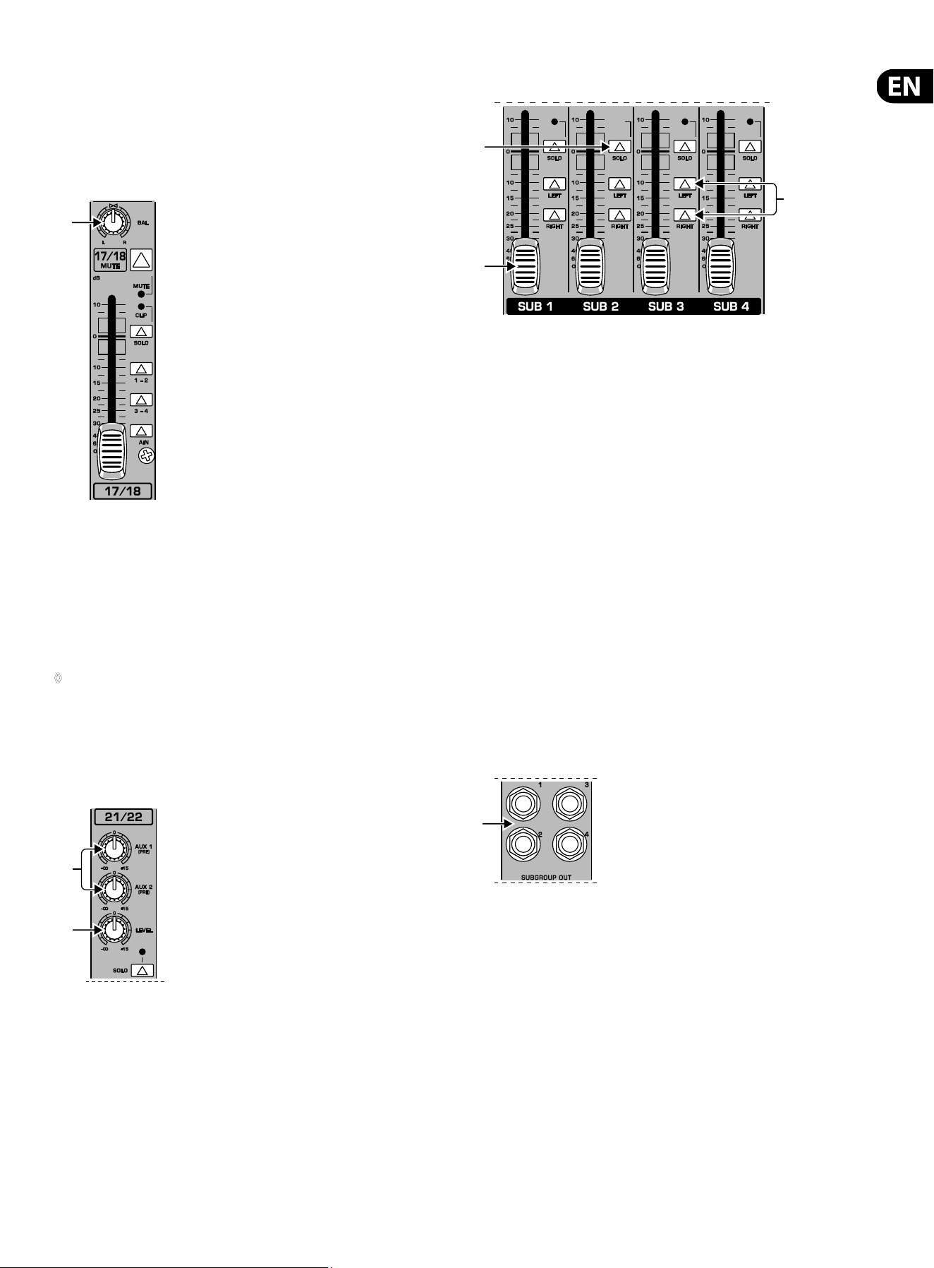
(22)
Fig. 2.7: Channel fader, balance control, mute switch, etc.
(22) The BAL(ANCE) control has the same function as the PANcontrol on
the mono channels. It determines the relative volume of the left and
right input signals before they are routed to the stereo main mix bus
(ortotwosubgroups).
All other control elements of the stereo channels work in the same ways as their
counterparts on the mono channels (faders, MUTE switches, etc.).
◊ Please note: When you route a stereo channel to the subgroups
using the SUB switches, please be sure to set the BAL control to
its mid position, so that the signal is sent to two subgroups and
remains stereo.
2.3 Stereo channels 21-24 (SX2442FX) or
29-32 (SX3242FX)
(23)
(24)
Fig. 2.8: Auxiliary stereo channels
Your EURODESK has two stereo channels with an aux send section (23)
(AUX 1 andAUX 2) and one LEVEL control. (24) For these channels, the aux buses
are hard-wired to pre-fader and are therefore particularly useful for monitoring.
They have no routing switches and are always sent to the main mix. Like the
normal stereo channels they have two line-level inputs on ¼" TRS connectors
forthe left and right channels, and a SOLO switch.
Similar to the CD/TAPE inputs (see
(49)) the auxiliary stereo channels
can be connected to CD players, tape decks, etc., for example, to feed in
playbackmaterial.
2.4 Subgroups 1 - 4
()
()
()
Fig. 2.9: Subgroups 1 - 4
The EURODESK has 4 subgroups enabling you to create mono or stereo mixes
from multiple input signals. Subgroups are controlled from one (mono) or two
(stereo) subgroup faders. Additionally, it is possible to connect the subgroup
outputs as tape sends to a multi-track recorder.
(25) The subgroup faders determine the volume of the subgroup signal at the
subgroup output
(28). Depending on the position of the routing switch (27)
youcan thus control the subgroup volume in the main mix.
(26) The SOLO switch routes the subgroup signal to the solo bus (Solo In Place)
or PFL bus (Pre Fader Listen), so that you can monitor the subgroup signal
without aecting the main or sub output signals. The signal to be monitored
is taken either pre (PFL, mono) or post-subgroup fader (Solo,stereo),
depending on the position of theSOLO/PFL switch
(40)). The SOLO LED
illuminates when the SOLO switch is pressed.
(27) Use the routing switches for the subgroups to send the subgroup signal to
the main mix. You can route it to the left stereo side (=LEFT pressed), to the
right stereo side (=RIGHT pressed) or to both (=LEFT and RIGHT pressed).
Forexample, when you have created a stereo submix using subgroups
1and 2, be sure to route group 1 to the left and group 2 to the right side
to maintain proper stereo positioning. If it is a mono submix with just one
subgroup, route it to the left and right sides of the mainmix to make the
signal audible on both sides.
()
Fig. 2.10: Subgroup outputs 1 - 4
(28) These four SUBGROUP OUT (puts) carry the signals of the individual
subgroups. For multi-tracking connect the outputs to the inputs of a
multi-track recorder (seechapter 4.1 “Studio set-up”).
8 EURODESK SX3242FX/SX2442FX User Manual
2.5 Mono out section for
subwooferapplications
Using this auxiliary mono output you can route the main mix signal to a separate
power amp. The tunable low-pass lter allows you to limit the signal content to
the low-frequency range to get a perfect subwoofer signal. This signal is mono
because very low frequencies disperse quickly, so there would be no benet to
position this signal in the stereo mix.
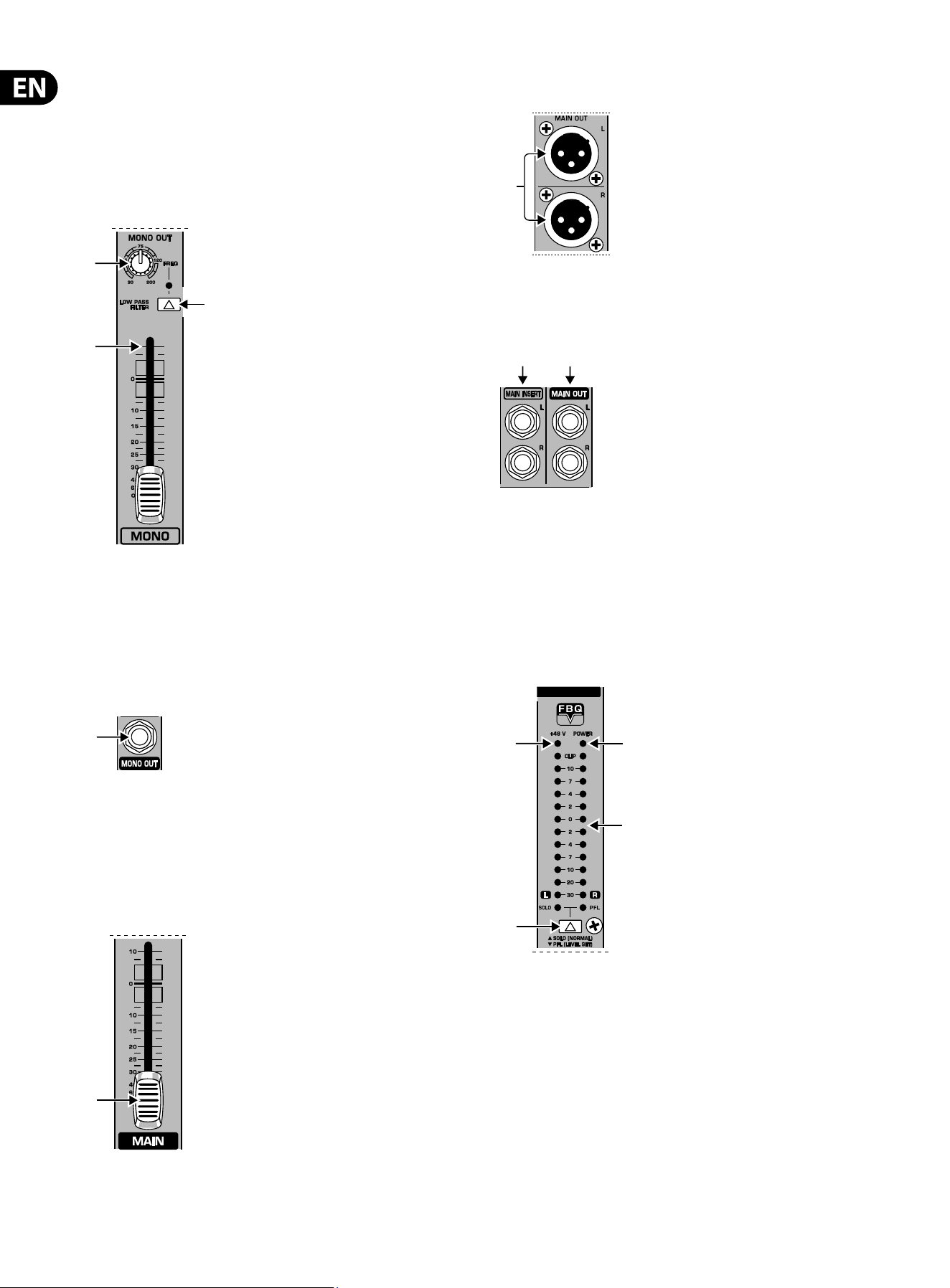
()
()
(
)
Fig. 2.11: Mono out fader and low-pass lter
(29) The MONO fader controls the volume of the signal present at the
MONO OUT (see
(32)).
(30) The FREQ control adjusts the cut-o frequency of the low-pass lter
(30 to 200 Hz). Frequencies above cut-o are ltered out when activated.
(31)
Use the LOW PASS FILTER switch to activate the lter function (LEDilluminates).
()
g. 2.12: Mono out connector
(32) The MONO OUT connector provides the line-level mono signal for
connection to the inputs of a power amp or active speaker. You can also use
this output as a monitor bus, e.g. to connect a headphone amplier. In this
case, thesignal should of course not be limited by the low-pass lter.
2.6 Main out section
()
Fig. 2.13: Main out fader
(33)
Use this high-precision MAIN fader to control the output level of the main mix.
()
Fig. 2.14: XLR main out connectors
(34) The MAIN OUT(puts) are balanced XLR connectors with a nominal operating
level of +4 dBu and provide the main mix signal.
()()
Fig. 2.15: Main out connectors and main insert
(35) The MAIN OUT ¼" TRS connectors outputs also provide the main mix signal.
(36) Like the channel inserts, the MAIN INSERT connectors can be used to
connect a dynamics processor or equalizer for further processing of the
mix signal. The MAIN INSERT refers to the Main Outs (XLR and ¼"TRS
connectors), theMONO OUT (see
(32)) and, if the MAIN switch in the
PHONES/CONTROL ROOM section is pressed, also to the PHONES/CTRL ROOM
output (see
(46)).
()
()
()
()
Fig. 2.16: Level meter
(37) The red “+48 V” LED illuminates when phantom power is on.
Phantompower is required for the operation of condenser microphones,
andcan be switched on with the corresponding switch on the rear of
theconsole.
(38) The POWER LED is illuminated when the console is switched on.
(39) The high-precision level meter accurately indicates the output signal level.
For example, when you press the SOLO switch on one of the input channels,
its signal level will be displayed here, either pre-fader (PFL) or post-fader
(SOLO), depending on the position of the SOLO/ PFL switch (see
(40)). In PFL
mode only the left display is active, because the PFL signals are mono.
9 EURODESK SX3242FX/SX2442FX User Manual
(40) The SOLO/PFL switch determines whether the monitored signal is pre
(PFL) or post-fader (SOLO) after pressing the SOLO/PFL switch (the LED
illuminates). The level meter indicates the corresponding signal (see
(39)).
When you adjust a signal with the GAIN control, it is advisable to select PFL
mode, so that the level shown is independent of the channel fader position.
2.6.1 Talkback
The talkback function of the EURODESK allows you to communicate with
the musicians in the recording room or on the stage. The talkback signal
is presentatthe AUXSEND outputs, which are particularly useful for
monitor/headphonemixes.
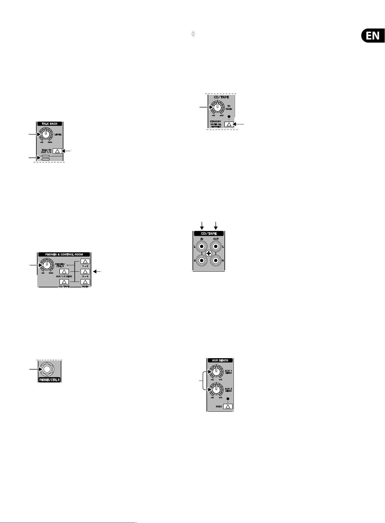
()
()
()
Fig. 2.17: Talkback section
(41) The LEVEL control determines the volume of the talkback signal at the
AUX1/2 outputs.
(42) Use the TALK TO AUX 1/2 switch to activate the built-in talkback
microphone. Its signal is sent to the AUX SEND jacks 1 and 2. Keep the
switchpressed while you’re speaking.
(43) This is the built-in talkback microphone.
2.6.2 Phones & control room
()
()
Fig. 2.18: Phones/control room section
(44) The PHONES/CTRL R control adjusts the volume of the headphones
connected to the PHONES/ CTRLROOMOUT jack (see
(46)). If you have an
active monitor speaker or power amp connected here, you can also control
the monitor volume.
(45) These switches select the signal sent to the PHONES/ CTRL ROOM jack.
Available sources are: MAIN, CD/TAPE, AUX 1/2 and subgroups 1 - 2 and 3 - 4.
()
Fig. 2.19: Phones/control room output
(46) Connect your headphones or monitor speaker to the PHONES/CTRL
ROOMOUT ¼" TRS connector.
◊ IMPORTANT! High volume levels may damage your hearing and/or
your headphones/loudspeakers. To avoid switch-on/off thumps from
the console and any downstream devices, always make sure that the
power amp(s) or active speaker(s) are the last components that are
switched on and the first to be switched off. Always make sure that the
appropriate volume is set.
2.7 CD/Tape
()
()
Fig. 2.20: CD/tape
(47) TO MAIN controls the volume of, for example, a CD player connected to the
CD/tape input connectors (see
(49)).
(48) When the STANDBY switch is pressed, all input channels are muted. Only the
CD/tape signal will be routed to the main mix. In this way, you can prevent
the microphones from pickung up unwanted sounds or noise that would
interfere with CD playback during a break. The main mix and channel faders
can remain in their normal positions while playing back music from CD
(using the CD/ TAPEINPUTs
(49)), so you don’t lose your mix.
()()
Fig. 2.21: CD/tape connectors
(49) The CD/TAPE INPUT RCA connectors are for the connection of CD players,
tape decks or other line-level sources. The signal volume is adjusted with
theTOMAINcontrol.
(50) The CD/TAPE OUTPUT RCA connectors provide the stereo main mix signal to
a tape deck or DAT recorder to record your mix. The signal is taken pre-fader,
so that it will not be inuenced by the fader positions.
2.8 Master Aux Send 1 and 2
()
Fig. 2.22: Master aux sends
10 EURODESK SX3242FX/SX2442FX User Manual
(51) These are the master AUX SEND controls 1 and 2 for adjusting the volume
level sent to the corresponding auxsend connectors (see
(52)). This way,
youcan control the mix of all AUX 1 or AUX 2 signals of the input channels.
The AUX SEND section also has a SOLO switch.
()
Fig. 2.23: Master aux send outputs
(52) Use the AUX SEND outputs 1 and 2 to take the master AUX SEND
signals and route them to an external eects device or your monitor
speakers. Subsequently, you can return the eect signal, e.g. via the
STEREOFXRETURN inputs (see
(67)) or specic inputchannels.
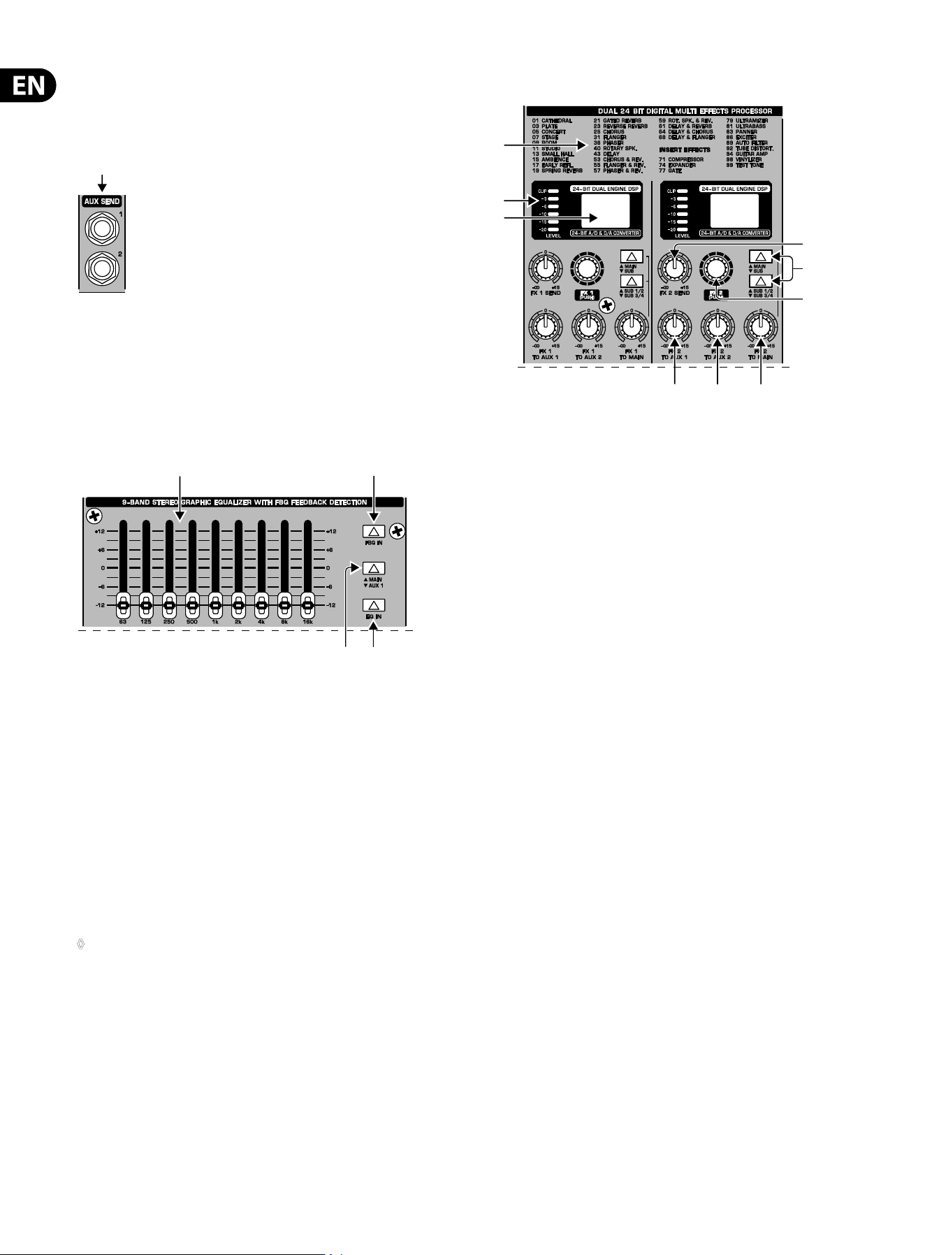
2.9 Graphic 9-band stereo equalizer
() ()
()
()
Fig. 2.24: The graphic stereo equalizer
(53) Your EURODESK is equipped with a graphic 9-band stereo equalizer
processing either the main or the AUX1 signal. Use the EQ to adapt the
soundto the room acoustics.
(54) Use the EQ IN switch to switch the equalizer on. In this case, the fader
LEDsilluminate.
(55) With the MAIN/AUX 1 switch you can determine the signal to be processed,
either main or AUX 1.
(56) Press the FBQ IN switch to activate the FBQ Feedback Detection System.
Thefrequencies causing feedback are indicated by the brightly lit fader
LEDs, while all other LEDs are darker. Simply lower the level of the brightly
litfaders until feedback disappears.
◊ When the switch is in the “AUX 1” position (see (55)), the EQ fader
LEDs show both the MAIN and the AUX 1 signal simultaneously.
However, if feedback occurs in one of the signals, those signals without
feedback will be faded out to enable clear identification of where
feedback is occurring. If the MAIN signal happens to be the one carrying
feedback, put the switch
(55) to “MAIN” and then use the 9-band EQ to
remove the feedback.
2.10 Eects section
() ()
()
()
()
()
()
()
()
Fig. 2.25: The digital eects processor
(57) Here you will nd a list of all multi-eects presets (seealso chapter 3
“Digital eects processor”).
(58) The FX LED level meters show the eects processor’s input signal.
Besure that the clip LED only illuminates with signal peaks. If it is lit
all the time, theeects processor is overloading and hence producing
unpleasantdistortion.
(59) The Eect displays show the currently selected presets.
(60) This is the master FX 1 (or 2) SEND control for adjusting the volume of all
FXsend signals at the corresponding FX send jacks (see
(66)) and at the
inputs of the built-in eects processor. Use it to control the master signal of
all FX 1/FX 2 signals from the input channels. Whenneither of the FX SEND
controls is turned up, the eects processor will not receive a signal.
(61) Turn the FX 1 (or FX 2) control to select an eects preset. Then, push it
briey to conrm your selection and activate the new eect.
(62) The FX 1 (or 2) TO AUX 1 controls allow you to add the eect signal from
the built-in eects processor (FX1orFX2) to the AUX 1 monitor signal.
Naturally,the eects processor must be provided with an input signal
(i.e. the FX controls in the channel strips plus the FXSENDcontrols and the
channel faders must be turnedup).
(63) This is the FX 1 (or 2) TO AUX 2 control adding the eect signal from the
eects processor to the AUX 2 monitor signal. See
(62) for further details.
(64) The FX 1 (or 2) TO MAIN control routes the eect signal either to the main
mix or the subgroups 1 and 2 (or3and4), depending on the position of the
selector switch (see
(65)). When it is hard left, no eect signal will be audible.
Here, too, the FX controls in the channel strips plus the FX SEND controls and
the channel faders must be turned up.

11 EURODESK SX3242FX/SX2442FX User Manual
(65) These selector switches route the eect signal to the main mix or to the
subgroups 1-2 or 3-4. If the MAIN/SUBswitch is not pressed, the eect
signal is sent to the main mix and the SUB 1/2 / SUB 3/4 switch below
is inoperative. If the upper switch is pressed (SUB), however, the lower
switchdetermines whether the eect signal is routed to subgroups 1 and 2
(SUB1/2) or 3 and4(SUB 3/4).
() ()
Fig. 2.26: FX send and return connectors
(66) The FX SEND 1 and 2 connectors also provide the masterFX send signals,
for example, to connect them to the inputs of an external eects device.
However, these are “dry” signals only with no “eect signals” from the
built-in eects processor!
(67) The Stereo FX RETURN inputs 1 and 2 return the eect signals from external
eects processors and add them to the main mix.
()
Fig. 2.27: Footswitch connectors
(68) The FOOTSW(ITCH) connector allows you to connect a standard dual
footswitch to separately enable/disable FX1 or FX 2. The tip of the ¼" plug
controls FX 1, the ring controls FX 2.
2.11 Rear panel
() () () () ()
Fig. 2.28: The rear panel of the EURODESK
(69) Use the POWER switch to put the mixer into operation. This switch should
always be in the “O” position when you connect your unit to the mains.
◊ Please note: The POWER switch does not fully disconnect the unit from
the mains. To disconnect the unit from the mains, pull out the main
cord plug or appliance coupler. When installing the product, ensure the
plug or appliance coupler is readily operable. Unplug the power cord
when the unit is not used for prolonged periods of time.
(70) With the PHANTOM switch you can activate the phantom power supply
for the XLR connectors of the mono channels for condenser microphones.
The +48 V-LED
(37) illuminates when phantom power is on. In most cases,
dynamic microphones can still be used as long as they are connected in
a balanced conguration. If in doubt, please contact the manufacturer of
yourmicrophone!
(71) The mains connection is a standard IEC receptacle. Anappropriate power
cord is supplied with the unit.
(72) FUSE HOLDER. Before connecting the unit to the mains, ensure that
the voltage setting matches your local voltage. Blown fuses should only
be replaced by fuses of the same type and rating. Please also read the
information given in chapter 6 “Specications”.
(73) SERIAL NUMBER.
3. Digital Eects Processor
Fig. 3.1: List of all eects presets
99 FIRST-CLASS PRESETS
Here is the list of all multi-eects presets. Thebuilt-in
eectsprocessor oers you various standard eects such as
reverb, chorus, anger, delay and a variety of combination
eects fromour renowned studio eects processor
VIRTUALIZERPRODSP2024P. Use the FX control on thechannels and the FX SEND
control to supply the eectsprocessor with signals. A built-in digital stereo
eectsprocessor has the benet of no external wiring, thusreducing the risk of
ground loops or level dierences. Handling is therefore much easier.
PARALLEL FX
The eects presets 1 to 70 provide classic “add-to-mix”eects. So, when you
turn up the FX 1 (or 2) TOMAINcontrol, you create a mix of the (dry) channel
signaland the eect signal. The balance between the twosignals can be set
withthe FX send and FX 1/2TOMAINcontrols.
This also applies to adding eect signals to the AUX1(or2) monitor mix, withthe
exception that the mix here is adjusted with the AUX 1 (or 2) control in the
channel strip and the FX TO AUX 1 (or 2) potentiometer. Of course, the eects
processor must receive a signal from the channel using the FX 1 (or 2) control.
Make sure that the PREswitch in the corresponding channel strip(s) is pressed.
Otherwise,theAUX buses will be set post-fader making the volume of the
AUXmonitor signal dependent on the position of the channel fader(s).
INSERT FX (channel is muted)
Eects presets #71 and higher process the entire signal, unlike the “add-to-
mix” eects. When you use an insert preset, be sure to separate the respective
channel from all buses (SUB button and MAIN button not pressed) and only
route the eect signal to the main mix (FX 1/2 control, FXSEND 1/2 control and
FXTOMAIN1/2 control).
◊ The channel fader of the corresponding channel remains active and
governs (in combination with the FX controls) the signal level sent to
the built-in effects processors.
12 EURODESK SX3242FX/SX2442FX User Manual
4. Wiring Examples
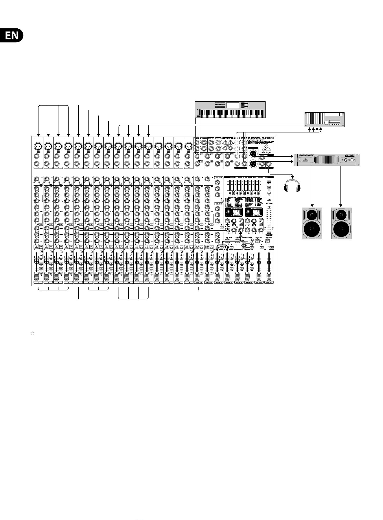
4.1 Studio set-up
The following wiring example shows a studio set-up for 4-track-recording:
thedrums are mixed down to two subgroups and then routed via the subgroup
outputs to two tracks of the multi-track recorder. The remaining two subgroups
are used to record the guitar, keyboard (stereo channel) and two vocal signals
on the remaining two tracks. The four return paths from the recorder are
connectedto four separate mono input channels on the EURODESK. Thebuilt-in
compressor is used only for the bass, which is why this input channel isseparate
from all buses (SUB and MAIN switch not pressed). The bass signal is directly
routed from the built-in eects processor to the respective subgroups
(FXTOMAIN control). The MAIN/SUB switch in the FX1 section is pressed,
butNOTthe SUB 1/2 SUB 3/4 button.
Fig. 4.1: Wiring the console for studio operation
◊ Please make sure that none of the subgroup routing switches
(1-2 and 3-4) is pressed in the channels connected to the recorder
returns. Otherwise, a feedback loop will be created as soon as you
start recording. Only press the MAIN switch on these input channels,
so that the tape return signals are routed to the main outs and
Phones/CTRL room outputs of the console.
Multi-track-
recorder
EUROPOWER EP1500
HPS3000
TRUTH B2030P
Bass
Guitar
Vocals 1
Vocals 2
Tape Returns
Keyboard
Subgroups Outs
SUB 3-4 switch
pressed
SUB 3-4 switch
pressed
MAIN switch
pressed
SUB 1-2 switch
pressed
SUB/MAIN switches
not pressed
LR
Drums
K
I
C
K
D
R
U
M
S
N
A
R
E
O
V
E
R
H
E
A
D
L
O
V
E
R
H
E
A
D
R
13 EURODESK SX3242FX/SX2442FX User Manual
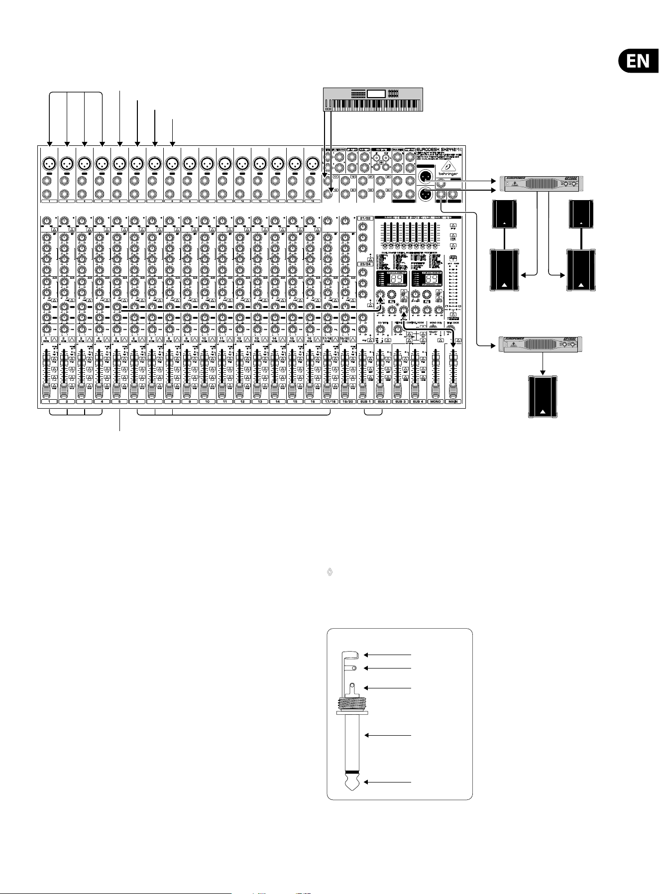
4.2 Live set-up
EUROLIVE PROFESSIONAL
B1220 PRO
EUROPOWER EP1500
EUROPOWER EP1500
2 x EUROLIVE PROFESSIONAL
Stack (B1800X PRO & B1220 PRO)
K
I
C
K
D
R
U
M
S
N
A
R
E
O
V
E
R
H
E
A
D
L
O
V
E
R
H
E
A
D
R
LR
Bass
Guitar
Vocals 1
Vocals 2
Keyboard
L/R switch
pressed
MAIN switch
pressed
SUB 1-2 switch
pressed
SUB/MAIN switches
not pressed
Drums
Fig. 4.2: Wiring the console for live operation
This example shows a classic live set-up. As in the studio example, fourdrum
microphones, bass, keyboard (stereo channel), guitar and two vocal microphones
are connected. The four drum channels (kick drum, snare, overhead L, overhead R)
are mixed down to two subgroups and then routed to the main mix. This way,
it is possible to conveniently control the volume of the entire drums in the main
mix with the two subgroup faders. The built-in compressor insert eect is used
for the bass. The corresponding input channel is separate from all buses and the
bass signalis routed directly from the internal eects processor to the main mix
bus. TheMAIN/SUB switch must not be pressed in this case and the position of the
SUB1/2 SUB 3/4 switch is irrelevant.
5. Audio Connectors
The inputs and outputs of the BEHRINGER EURODESK are designed as unbalanced
¼" TS connectors—except for the balanced line inputs of the mono and stereo
channels and the main out connectors. Of course, all inputs and outputs work
with both balanced and unbalanced connectors. The tape ins and outs are stereo
RCA connectors.
◊ Please ensure that only qualified personnel install and operate the
EURODESK. During installation and operation, the user must have
sufficient electrical contact to earth. Electrostatic charges might
affect the operation of the unit.
strain relief clamp
sleeve
tip
sleeve
(ground/shield)
Unbalanced ¼" TS connector
tip
(signal)
Fig. 5.1: ¼" TS connector
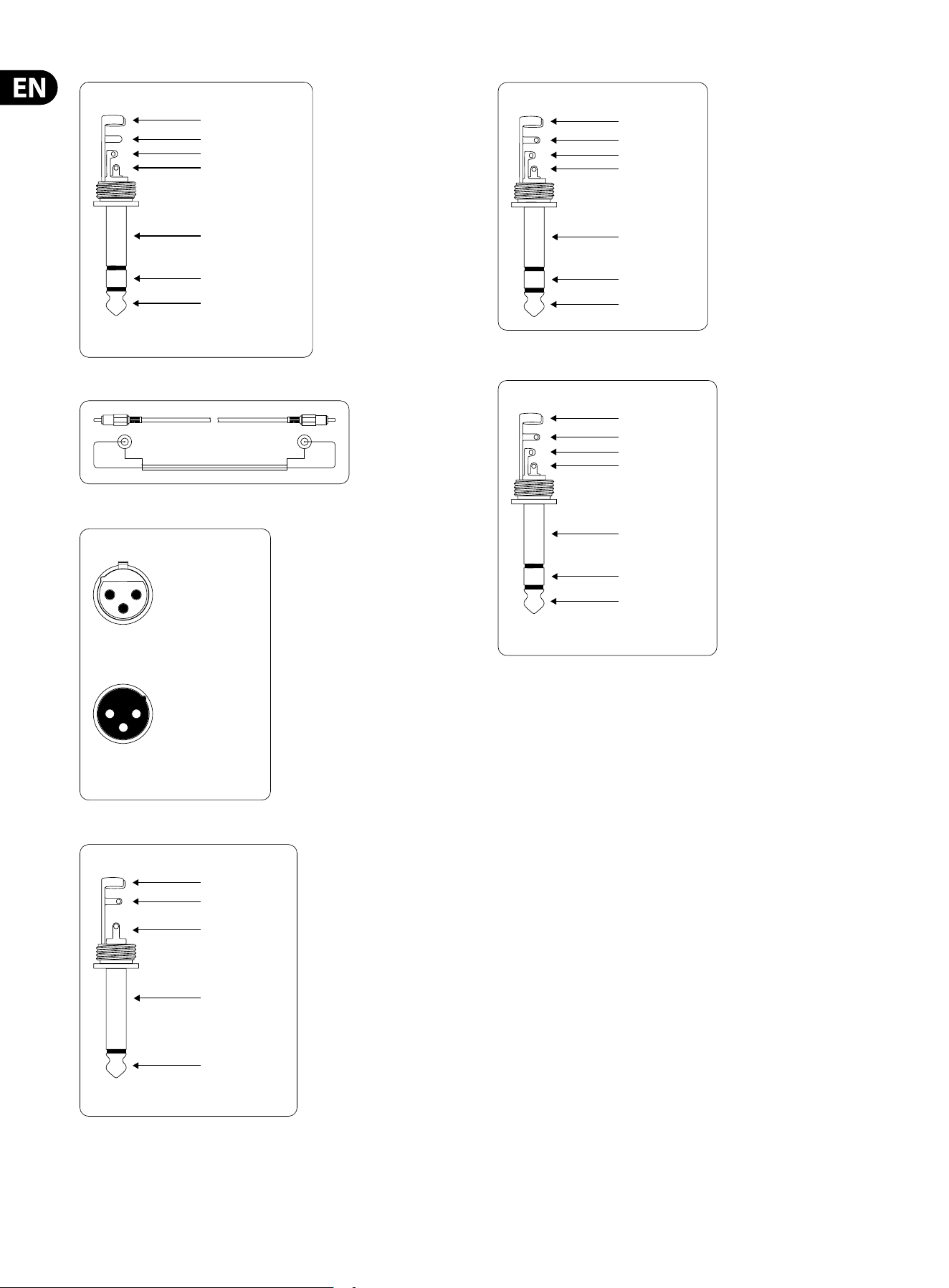
14 EURODESK SX3242FX/SX2442FX User Manual
strain relief clamp
sleeve
ring
tip
sleeve
ground/shield
For connection of balanced and unbalanced plugs,
ring and sleeve have to be bridged at the stereo plug.
Balanced ¼" TRS connector
ring
cold (-ve)
tip
hot (+ve)
Fig. 5.2: ¼" TRS connector
shield
sleevesleeve
tip tip
Fig. 5.3: RCA cable
output
For unbalanced use, pin 1 and pin 3
have to be bridged
1 = ground/shield
2 = hot (+ve)
3 = cold (-ve)
input
12
3
1
2
3
Balanced use with XLR connectors
Fig. 5.4: XLR connectors
strain relief clamp
sleeve
tip
sleeve
pole 1/ground
tip
pole 2
The footswitch connects both poles momentarily
¼" TS footswitch connector
Fig. 5.5: ¼" TRS footswitch connector
strain relief clamp
sleeve
ring
tip
sleeve
ground/shield
¼" TRS headphones connector
ring
right signal
tip
left signal
Fig. 5.6: ¼" TRS connector for headphones
strain relief clamp
sleeve
ring
tip
sleeve
ground/shield
Connect the insert send with the input and the
insert return with the output of the eects device.
Insert send return ¼" TRS connector
ring
return (in)
tip
send (out)
Fig. 5.7: Insert send and return ¼” TRS connector

15 EURODESK SX3242FX/SX2442FX User Manual
6. Presets
Eect Description Application examples
PARALLEL EFFECTS
C
athedral Very dense and long reverberation of a large cathedral. Solo instruments/vocals in slow pieces.
Plate Simulates the sound of early plate reverberators. A classic for drums (snare) and vocals.
Concert Simulates a small theater or large concert hall. Creates an “atmosphere” (e.g. radioplay voices).
Stage Very dense reverb, especially for live applications. Dissipates the sound of keyboard pads, for example.
Room You can clearly hear the walls of the room. Reverb eect that isn’t directly noticeable.
Studio Adds spaciousness to the sound; signals sound natural, not “at”. Gives a sound source more “class” in the mix.
Small Hall Simulates a small, lively (strongly reecting) hall. Perfect for processing drums.
Ambience Reproduces a middle-sized room without late reections. Extremely versatile eect.
Early Reections Very dense reverb with pronounced early reections. Drums, percussion, slap bass
Spring Reverb Simulates a classic spring reverberation. Extremely versatile eect.
Gated Reverb Reverb that is synthetically cut o Produces a very “crisp” snare sound.
Reverse Reverb Reverb with reversed envelope, i.e. it slowly gets louder. Produces a very spaced out vocal sound.
Chorus Slight detuning of the original signal. Extremely versatile eect (guitar, vocals, bass, keyboards etc.).
Flanger A slightly delayed signal is added to the original signal, producing phase shifting of the signals. Extremely versatile eect (guitar, vocals, bass, keyboards etc.).
Phaser Another phase-shift eect. Extremely versatile eect (guitar, vocals, bass, keyboards etc.).
Rotary Speaker Simulation of a classic eect for electronic organ. Organ/keyboards.
Delay Delay of the input signal with several repetitions. Extremely versatile eect.
Chorus & Reverb Combination of chorus and reverb. A classic eect for vocals.
Flanger & Reverb Flanger combined with a reverb eect. All-purpose eect.
Phaser & Reverb Phaser combined with a reverb eect. All-purpose eect.
Rotary Speaker & Reverb Rotary Speaker eect combined with reverb. Organ/keyboards/electric guitar.
Delay & Reverb Delay combined with reverb. The most common combination for vocals, solo guitar, etc.
Delay & Chorus Widens the signals and produces interesting repetition eects. Makes vocals stand out in the mix. Good intelligibility is preserved.
Delay & Flanger Similar to Delay & Chorus, but with audible up/downward modulation. Ideal for creating a slightly spaced out sound.
INSERT EFFECTS
Compressor Soft or loud passages are raised or lowered in level respectively. Single signals, especially from microphones.
Expander
No dynamics limitation (see Compressor), but quite the opposite:
interference(noise, hum, etc.) is reduced in level.
Single signals, especially from microphones.
Gate A gate opens for a specic period of time to make a specic signal pass, and then closes abruptly. “Controls” feedback-prone microphones/eliminates interference.
Ultramizer Extremely ecient compression through automatic adaptation of compression parameters. Gives mix signals a constant output level.
Ultrabass Combines sub-harmonics processor, bass exciter and limiter.
Gives keyboard sounds some special “class”/sound eect for
electric basses.
Panner The signal “wanders” between the sides of the stereo basis. Special eect, e.g. for radioplay soundtracking.
Exciter Adds synthetic harmonics to the signal, resulting in increased presence and “loudness”. Both mix and single signals. Improves intelligibility of vocal signals.
Auto Filter Level-dependent boost of a specic frequency band, similar to auto-wah eect for electric guitars. DJ-ing/sound eects for live events/electric guitar or bass.
Tube Distortion Simulates the tube distortion of classic guitar ampliers. Electric guitar/vocals/keyboards.
Guitar Amp Guitar amp simulation. Electric guitar or bass.
Vinylizer Adds the clicks and noise of old vinyl records. DJ-ing/sound eects for live events.
Test Tone 1-kHz test tone. Makes P.A. level setting easier.

16 EURODESK SX3242FX/SX2442FX User Manual
7. Specications
Mono Inputs
Microphone inputs (XENYX Mic preamp)
Type XLR connector, electronically
balanced, discrete input circuit
Mic E.I.N.
1
(20 Hz - 20 kHz)
@ 0Ω source resistance -134dB / 135.7dB A-weighted
@ 50Ω source resistance -131dB / 133.3dB A-weighted
@ 150Ω source resistance -129dB / 130.5dB A-weighted
Frequency Response
<10Hz - 160kHz -1dB
<10Hz - 200kHz -3dB
Gain range +10dB to +60dB
Max. input level +12dBu @+10dB GAIN
Impedance approx. 2.6kΩ balanced
Signal-to-noise ratio 110dB / 112dB A-weighted
(0dBu In @ +22dB GAIN)
Distortion (THD + N) 0.005% / 0.004% A-weighted
Line Input
Type ¼" TRS jack, electronically balanced
Impedance approx. 20kΩ balanced,
approx. 10kΩ unbalanced
Gain range -10dB to +40dB
Max. input level +22dBu @ 0dB GAIN
Fade-out attenuation
2
(Crosstalk attenuation)
Main fader closed 90dB
Channel muted 84dB
Channel fader muted 85dB
Frequency response (Mic In A Main Out)
<10Hz - 90kHz +0dB / -1dB
<10Hz - 160kHz +0dB / -3dB
Stereo Inputs
Type 2 x ¼" TRS jack, balanced
Impedance approx. 20kΩ balanced,
approx. 10kΩ unbalanced
Gain range -20dB to +20dB
Max. input level +22dBu @ 0dB GAIN
CD/Tape In
Type RCA connector
Impedance approx. 10kΩ
Max. input level +22dBu
Equalizer
EQ mono channels
LOW 80Hz / ±15dB
MID 100Hz to 8kHz / ±15dB
HIGH 12kHz / ±15dB
LOW CUT 80Hz, 18dB/oct.
EQ stereo channels
LOW 80Hz / ±15dB
LOW MID 500Hz / ±15dB
HIGH MID 3kHz / ±15dB
HIGH 12kHz / ±15dB
Channel Inserts
Type ¼" TRS jack, unbalanced
Max. input level +22dBu
AUX/FX Send
Type ¼" mono jack, unbalanced
Impedance approx. 120Ω
Max. output level +22dBu
FX Returns
Type ¼" mono jack, unbalanced
Impedance approx. 10kΩ
Max. input level +22dBu
Subgroup Outputs
Type ¼" mono jack, unbalanced
Impedance approx. 120Ω
Max. output level +22dBu
Main Outputs (XLR)
Type XLR connector,
electronically balanced
Impedance approx. 240Ω balanced,
approx. 120Ω unbalanced
Max. output level +28dBu

17 EURODESK SX3242FX/SX2442FX User Manual
Main Outputs (¼")
Type ¼" TRS jack, electronically balanced
Impedance approx. 240Ω balanced,
approx. 120Ω unbalanced
Max. output level +28dBu
Main Inserts
Type ¼" TRS jack, unbalanced
Max. input level +22dBu
Mono Output
Type ¼" mono jack, unbalanced
Impedance approx. 120Ω
Max. output level +22dBu
Low pass variable, 30Hz to 200Hz, 18dB/oct.
Phones/CTRL Room Output
Type ¼" TRS jack, unbalanced
Max. output level +19dBu / 150Ω (+25dBm)
CD/Tape Out
Type RCA connector
Impedance approx. 1kΩ
Max. output level +22dBu
DSP
Type Texas Instruments
Converter 24-bit delta-sigma,
64/128-times oversampling
Sampling rate 46kHz
Main Mix System Data
3
(Noise)
Main mix @ -∞, channel fader @ -∞ -100dB / -102.5dB A-weighted
Main mix @ 0dB, channel fader @ -∞ -82dB / -85dB A-weighted
Main mix @ 0dB, channel fader @ 0dB -72dB / -75dB A-weighted
Power Supply
Power consumption 50W
Fuse (100 - 240V~, 50/60Hz) T 2,0A H 250V
Mains connector Standard IEC receptacle
Physical/Weight
SX2442FX
Dimensions (H x W x D) 3.9 x 26.9 x 16.1"
100 x 682 x 410mm
Weight (net) 19lbs / 8.6kg
SX3242FX
Dimensions (H x W x D) 3.9 x 35.3 x 16.1"
100 x 896 x 410mm
Weight (net) 24.3lbs / 11.0kg
1
Equivalent Input Noise
2
Measuring conditions: 1 kHz rel. to 0 dBu; 20 Hz - 20 kHz; line input; main output; unity gain.
3
20 Hz - 20 kHz; measured at main output. Channels 1 - 4 unity gain; EQ flat; all channels on main mix;
channels 1/3 as far left as possible; channels 2/4 as far right as possible; reference = +6 dBu.
BEHRINGER is constantly striving to maintain the highest professional standards. As a result of these efforts,
modifications may be made from time to time to existing products without prior notice. Specifications and
appearance may differ from those listed or illustrated.

18 EURODESK SX3242FX/SX2442FX User Manual
FEDERAL COMMUNICATIONS
COMMISSION COMPLIANCE
INFORMATION
Responsible Party Name: MUSIC Group Services NV Inc.
Address: 5270 Procyon Street
Las Vegas, NV 89118
USA
Phone Number: +1 702 800 8290
EURODESK SX3242FX/SX2442FX
complies with the FCC rules as mentioned in the followingparagraph:
This equipment has been tested and found to comply with the limits for a ClassB
digital device, pursuant to part 15 of the FCC Rules. These limits are designed
to provide reasonable protection against harmful interference in a residential
installation. This equipment generates, uses and can radiate radio frequency
energy and, if not installed and used in accordance with the instructions, may cause
harmful interference to radio communications. However, there is no guarantee that
interference will not occur in a particular installation. If this equipment does cause
harmful interference to radio or television reception, which can be determined
by turning the equipment o and on, the user is encouraged to try to correct the
interference by one or more of the followingmeasures:
•
• Reorient or relocate the receiving antenna
•
• Increase the separation between the equipment and receiver
•
• Connect the equipment into an outlet on a circuit di erent from that to which the
receiver is connected
•
• Consult the dealer or an experienced radio/TV technician forhelp
This device complies with Part 15 of the FCC rules. Operation is subject to the
following two conditions:
(1) this device may not cause harmful interference, and
(2) this device must accept any interference received, including interference that may
cause undesired operation.
Important information:
Changes or modi cations to the equipment not expressly approved by MUSIC Group
can void the user’s authority to use the equipment.
EURODESK SX3242FX/SX2442FX

We Hear You