
BRK4T
BRK10T
Body Repair Kits
Model Capacity
BRK4T 4 Ton
BRK10T 10 Ton
Printed in China
BRK4T-M0_072017
Read this manual and follow all the Safety Rules and Operating Instructions before using this product.
This is the safety alert symbol. It is used to alert you to potential personal injury hazards.
Obey all safety messages that follow this symbol to avoid possible injury or death.
!
⒀⑾⑥⑾⒀⒆
⑩㈢
㙀䴷࣋㺘
03D
㙀䴷࣋㺘
03D
© July 2017
Operating Instructions & Parts Manual
MATCO TOOLS
http://www.matcotools.com
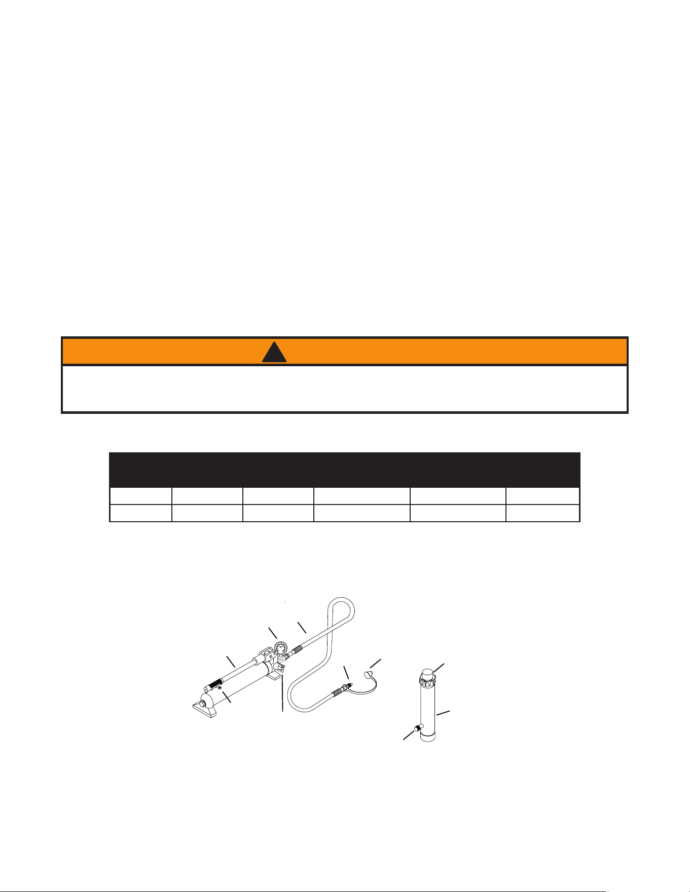
Figure 1 - BRK4T and BRK10T Components
2
Oil Filler
Screw
Handle
Release Valve
Plunger
Hose
Hose
Coupler
Ram Coupler
Ram
Dust Cover
Gauge
SAFETY AND GENERAL INFORMATION
Save these instructions. For your safety, read, understand, and follow the information provided with and on this
device before using. The owner and/or operator shall have an understanding of the device, its operating characteristics
and safety operating instructions before operating the equipment. The owner and/or operator shall be aware that use
and repair of this product may require special skills and knowledge. Instructions and safety information shall be read
to and discussed with the operator in the operator's native language, making sure that the operator comprehends
their contents, before use of this equipment is authorized. If any doubt exists as to the safe and proper use of this
device, remove from service immediately.
Inspect before each use. Do not use if abnormal conditions such as cracked welds, damaged, loose or missing
parts are noted. Any equipment that appears damaged in any way, is found to be worn, or operates abnormally shall
be removed from service until repaired. If the equipment has been or is suspected to have been subjected to an
abnormal load or shock, immediately discontinue use until inspected by a factory authorized repair facility (contact
distributor or manufacturer for list of authorized repair facilities). It is recommended that an annual inspection be
made by an authorized repair facility. Labels and Operator's Manuals are available from the manufacturer.
PRODUCT DESCRIPTION
Matco Tools Body Repair Kits are designed to be used for pushing, spreading, and pressing of vehicle body panels
as well as various component parts and assemblies. A variety of attachments are included.
SPECIFICATIONS
Model
Pump
Capacity
Ram
Capacity
Ram
Number of
Attachments
Closed Height Extended Height
BRK4T 8,000 psi 4 Ton 10-3/4” 15-5/8” 14
BRK10T 10,000 psi 10 Ton 13-3/4” 19-3/4” 13
When using extension tubes and/or offset attachments, reduce rated capacity by 50% for each tube or
offset attachment connected. See Replacement Parts VHFWLRQ RQ SDJHV IRU LGHQWL¿FDWLRQ RI RIIVHW
attachments.
WARNING
!

3
6WXG\XQGHUVWDQGDQGIROORZDOOLQVWUXFWLRQVEHIRUHRSHUDWLQJWKLVGHYLFH
:HDUH\HSURWHFWLYHWKDWPHHWV$16,=DQG26+$VWDQGDUGV
'RQRWH[FHHGWKHUDWHGFDSDFLW\
8VHDSUHVVXUHJDXJHWKDWLQGLFDWHVSRXQGVRIIRUFHDSSOLHG
:KHQXVLQJH[WHQVLRQWXEHVSRVLWLRQWKHVKRUWHVWWXEHIDUWKHVWIURPWKHF\OLQGHU
'RQRWVXEMHFWWKHKRVHWRH[WUHPHFROGKHDWVKDUSVXUIDFHVDEUDVLRQRULPSDFW
'RQRWDOORZWKHKRVHWRNLQNWZLVWFXUORUEHQGVRWLJKWO\WKDWLWUHVWULFWVÀXLGÀRZ
0DNHVXUHVHWXSLVVWDEOHDQGVHFXUHEHIRUHSHUIRUPLQJDQ\ZRUN
1RDOWHUDWLRQVRUPRGL¿FDWLRQVVKDOOEHPDGHWRWKLVSURGXFW
2QO\FRPSRQHQWVVXSSOLHGZLWKWKLVNLWVKDOOEHXVHGZLWKWKLVNLW
)DLOXUHWRKHHGWKHVHPDUNLQJVPD\UHVXOWLQSHUVRQDOLQMXU\DQGRUSURSHUW\GDPDJH
ADDITIONAL SAFETY MESSAGES
$YRLGVKRUWUXQVRIVWUDLJKWOLQHWXELQJ6WUDLJKWOLQHUXQVGRQRWSURYLGHIRUH[SDQVLRQDQGFRQWUDFWLRQGXHWR
pressure and/or temperature changes.
/RQJWXELQJUXQVVKRXOGEHVXSSRUWHGE\EUDFNHWVRUFOLSV%HIRUHRSHUDWLQJWKHSXPSDOOKRVHFRQQHFWLRQV
PXVWEHWLJKWHQHGZLWKWKHSURSHUWRROV'RQRWRYHUWLJKWHQ&RQQHFWLRQVVKRXOGRQO\EHWLJKWHQHGVHFXUHO\DQG
OHDNIUHH2YHUWLJKWHQLQJFDQFDXVHSUHPDWXUHWKUHDGIDLOXUHRUKLJKSUHVVXUH¿WWLQJVWREXUVW
6KRXOGDK\GUDXOLFKRVHUXSWXUHEXUVWRUQHHGWREHGLVFRQQHFWHGLPPHGLDWHO\VKXWRIIWKHSXPSDQGUHOHDVH
DOO SUHVVXUH 1HYHU DWWHPSW WR JUDVS D OHDNLQJ SUHVVXUL]HG KRVH ZLWK \RXU KDQGV 7KH IRUFH RI HVFDSLQJ
K\GUDXOLFÀXLGLVXQGHUKLJKSUHVVXUHDQGFDQLQÀLFWLQMXU\
'RQRWSXOOSRVLWLRQRUPRYHVHWXSE\WKHKRVH'RLQJVRFDQGDPDJHWKHKRVH
+RVHVDOVRPXVW QRW FRPHLQFRQWDFW ZLWKFRUURVLYHPDWHULDOV VXFKDV EDWWHU\DFLGFUHRVRWHLPSUHJQDWHG
REMHFWVDQGZHWSDLQW1HYHUSDLQWDFRXSOHURUKRVH
,QVSHFWHDFKUDPDQGFRXSOHUEHIRUHHDFKXVHWRSUHYHQWXQVDIHFRQGLWLRQVIURPGHYHORSLQJ,QVSHFWWKHKRVH
for wear.
'RQRWXVHUDPVLIWKH\DUHGDPDJHGDOWHUHGRULQSRRUFRQGLWLRQ
'RQRWXVHUDPVZLWKEHQWRUGDPDJHGFRXSOHURUGDPDJHGWKUHDGV
8QGHUFHUWDLQFRQGLWLRQVWKHXVHRIDQH[WHQVLRQZLWKDK\GUDXOLFUDPPD\QRWEHDGYLVDEOHDQGFRXOGSUHVHQW
a dangerous condition.
$YRLGSLQFKSRLQWVRUFUXVKSRLQWVWKDWFDQEHFUHDWHGE\WKHORDGRUSDUWVRIUDP
7RKHOSSUHYHQWPDWHULDOIDWLJXHLIWKHUDPLVWREHXVHGLQDFRQWLQXRXVDSSOLFDWLRQWKHORDGVKRXOGQRWH[FHHG
85% of the rated capacity.
5DPPXVWEHRQDVWDEOHEDVHFDSDEOHRIVXSSRUWLQJWKHORDGZKLOHSXVKLQJRUOLIWLQJ
(QVXUHUDPLVIXOO\HQJDJHGLQWRRQWRDGDSWHUVH[WHQVLRQDFFHVVRULHV
8VHVKLPVIULFWLRQPDWHULDORUFRQVWUDLQWVWRSUHYHQWVOLSSDJHRIWKHEDVHRUORDG
'RQRWRIIFHQWHUORDGVRQDUDP7KHORDGFDQWLSRUWKHUDPFDQ³NLFNRXW´DQGFDXVHSHUVRQDOLQMXU\
1HYHUWU\WRGLVDVVHPEOHDK\GUDXOLFF\OLQGHU5HIHUUHSDLUVWRTXDOL¿HGDXWKRUL]HGSHUVRQQHO
.HHSUDPFOHDQDWDOOWLPHV
:KHQQRWLVXVHNHHSUDPIXOO\UHWUDFWHG
8VHDQDSSURYHGKLJKJUDGHSLSHWKUHDGVHDODQWWRVHDODOOK\GUDXOLFFRQQHFWLRQV7HÀRQWDSHFDQEHXVHG
LIRQO\RQHOD\HURIWDSHLVXVHGDQGLWLVDSSOLHGFDUHIXOO\WZRWKUHDGVEDFNWRSUHYHQWWKHWDSHIURPEHLQJ
LQWURGXFHGLQWRK\GUDXOLFV\VWHP$SLHFHRIWDSHFRXOGWUDYHOWKURXJKWKHV\VWHPDQGREVWUXFWWKHÀRZRIÀXLG
and adversely affect function.
WARNING
!
WARNING
!
BEFORE USE
1. Before using this product, read the owner's manual completely and familiarize yourself thoroughly with the
product, its components and recognize the hazards associated with its use.
2. Inspect before each use. Do not use if bent, broken, leaking or damaged components are noted.
3. Ensure all parts of your kit are included (ref. illustrations and parts list).
4. Remove dust caps and plugs from hose coupler and ram coupler.
&RQQHFWKRVHFRXSOHUWRUDPFRXSOHUHQVXULQJWKHUHDUHQRÀXLGOHDNV
6. Locate and open release valve. Close release valve clockwise and pump handle until ram is fully extended, then
open release valve counter-clockwise until ram has fully retracted.
:LWKUDPIXOO\UHWUDFWHGDQGUHOHDVHYDOYHRSHQSODFHSXPSLQKRUL]RQWDOSRVLWLRQ2SHQRLO¿OOHUVFUHZORFDWHG
RQUHVHUYRLUERG\7KLVZLOOUHOHDVHDLUWUDSSHGZLWKLQWKHUHVHUYRLU5HLQVWDOORLO¿OOHUVFUHZ
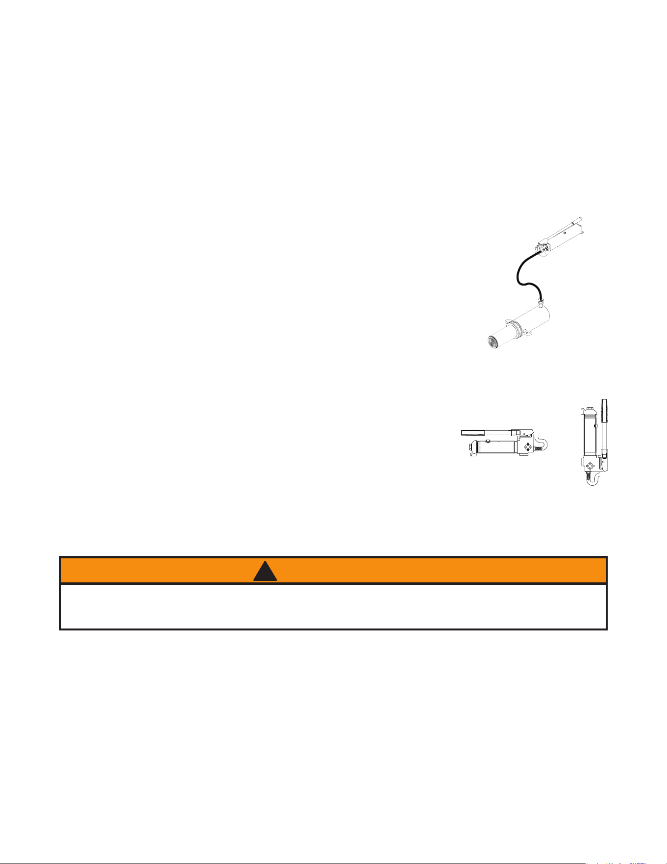
Bleeding Air from System
1. Bleed air from ram: Place pump at a higher elevation than the hose and ram
as shown in Figure 2. With the objective being to force air up stream to the
reservoir, close valve and extend ram as fast as possible. Open valve fully
allowing oil and air to return to reservoir. Repeat procedure two or three
times.
%OHHGDLUIURPSXPS:LWKUDPIXOO\UHWUDFWHGUHPRYHRLO¿OOHUVFUHZWROHW
SUHVVXUL]HGDLUHVFDSHWKHQUHLQVWDOORLO¿OOHUVFUHZ
General Instruction
1. Pump may be used in horizontal or vertical position as illustrated (ref. Figure.
3).
2. Attachments must be fully engaged before applying load.
3. Ensure load is centrally applied to attachment or ram saddle. Do not attempt
off-center loading.
4. Always monitor the force applied to work piece by using a load cell and indi-
cator, or monitor pressure developed in the ram by using an in-line pressure
gauge, then calculate the applied force using the formula:
F = P x A, where F = lbs force, P = pressure in psi, and A = effective
ram area in in
2
.
Ram Area of Model BRK4T is: 0.998 in
2
Ram Area of Model BRK10T is: 2.411 in
2
(ref. Load-Pressure Correlation chart on page 10)
5. If bowing or bending of ram or any attachment occurs during use, STOP IMMEDIATELY, release pressure and
reconsider application. Application may require higher capacity ram kit.
Basic Setup
7KHFDSDFLW\RIWKHERG\UHSDLUNLWFDQEHVLJQL¿FDQWO\DIIHFWHGE\WKHQXPEHURIDWWDFKPHQWVXVHGDQGWKHW\SH
of load applied. The approximate load capacity of each function setup is illustrated on page 5. When two or more
extension tubes are used together, be sure to position the shorter tube furthest from the ram.
OPERATION
Applying Pressure to Work Piece:
/RFDWHDQGFORVHUHOHDVHYDOYHE\WXUQLQJLWFORFNZLVHXQWLO¿UPO\FORVHG'RQRWRYHUWLJKWHQ
2SHUDWHE\SXPSLQJKDQGOH7KLVZLOOVHQGÀXLGIURPWKHSXPSUHVHUYRLULQWRWKHKLJKSUHVVXUHKRVHDVVHPEO\
and into the ram assembly.
3. Continue pumping until ram reaches desired position or overpressure situation is reached.
4
Figure 3 - Variable Position
Figure 2 - Pump/ram air bleed
When using extension tubes and/or offset attachments, reduce rated capacity by 50% for each tube or
offset attachment connected. See Replacement Parts VHFWLRQ RQ SDJHV IRU LGHQWL¿FDWLRQ RI RIIVHW
attachments.
WARNING
!
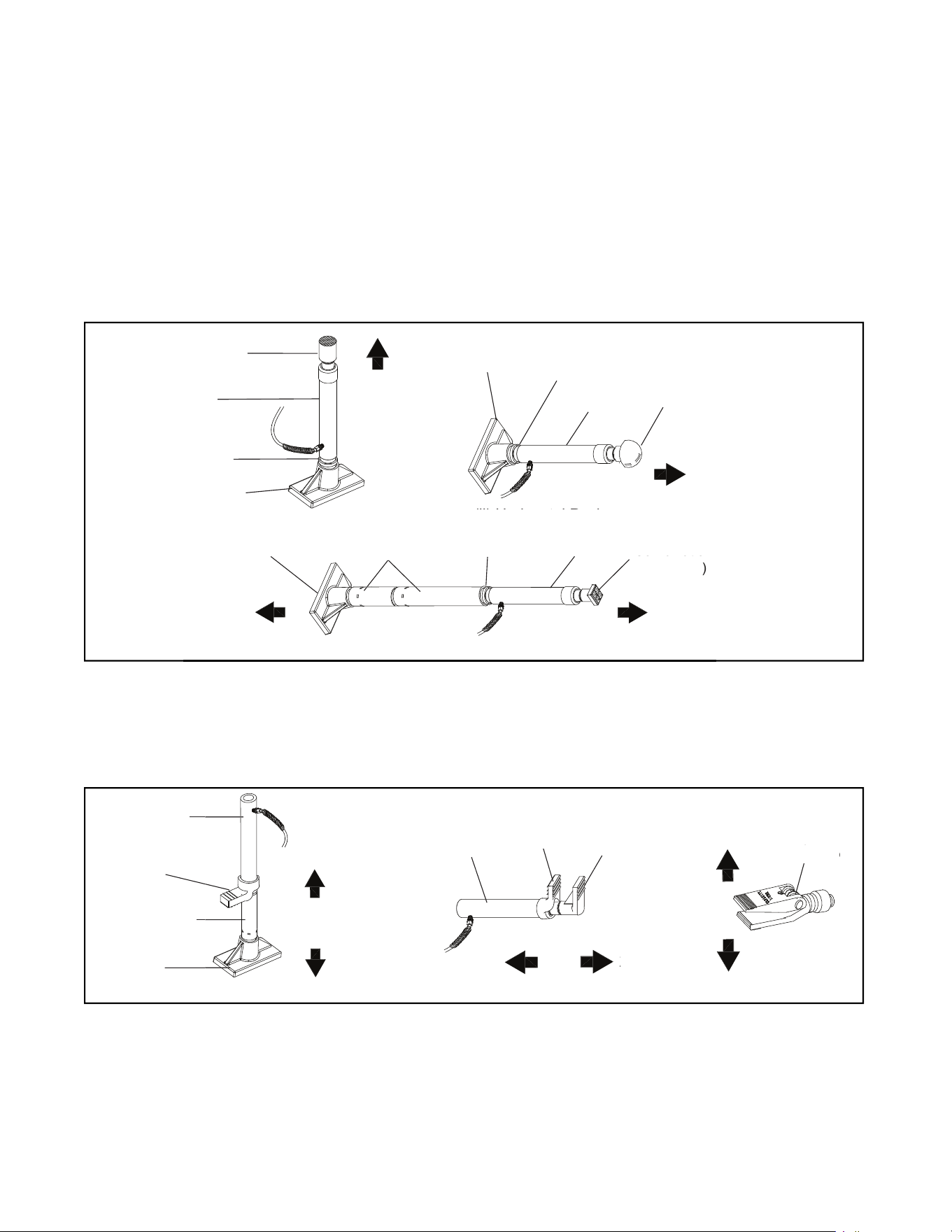
5
B. Spreading
(i) Vertical Spread
(ii) Horizontal Spread
(iii) Hydraulic Spreader
Ram Toe
Ram
Extension Tube
Flat Base
Ram Toe
Ram Toe
Ram
Plunger Toe
Hydraulic
Hydraulic
Spreader
Spreader
25%
25%
25%
25%
0.5 Ton
Flat Base
Male Connector
Ram
Combination
Extension Tube
Serrated Saddle
Ram
Male Connector
Flat Base
(i) Vertical Push
(ii) Horizontal Push
Rubber Head
100%
A. Pushing
(ii) Horizontal Push
Flat Base
Male Connector
Ram
Rubber Head
100%
Flat Base
Combination
Head (90
0
)
(iii) Horizontal Push with Extension
25%
Releasing Pressure on Work Piece:
Slowly, carefully turn the release valve counter-clockwise until ram retracts to desired position. Never turn release
valve more than 1/2 of a full turn. The ram return system is spring loaded and the release valve system is metered,
allowing controlled retraction of the ram.

6
MAINTENANCE
NOTICE: 8VHRQO\JRRGTXDOLW\K\GUDXOLFMDFNRLO$YRLGPL[LQJGLIIHUHQWW\SHVRIÀXLGDQG1(9(5XVHEUDNHÀXLG
WXUELQHRLOWUDQVPLVVLRQÀXLGPRWRURLORUJO\FHULQ,PSURSHUÀXLGFDQFDXVHSUHPDWXUHIDLOXUHRIWKHMDFNDQGWKH
SRWHQWLDOIRUVXGGHQDQGLPPHGLDWHORVVRIORDG3UHPLXPK\GUDXOLFMDFNRLOLVUHFRPPHQGHG
Adding oil
:LWKUDPIXOO\ORZHUHGVHWSXPSXQLWLQLWVQRUPDOOHYHOSRVLWLRQ/RFDWHDQGUHPRYHRLO¿OOHUVFUHZ
)LOOXQWLORLOLVZLWKLQRIWKHRLO¿OOHUVFUHZKROHRSHQLQJUHLQVWDOORLO¿OOHUVFUHZ
Changing oil
)RUEHVWSHUIRUPDQFHDQGLQFUHDVHGV\VWHPOLIHUHSODFHWKHFRPSOHWHÀXLGVXSSO\DWOHDVWRQFHSHU\HDU
:LWKUDPIXOO\ORZHUHGUHPRYHWKHRLO¿OOHUVFUHZIURPWKHSXPSUHVHUYRLUDVDERYH
/D\WKHSXPSRQLWVVLGHDQGGUDLQWKHÀXLGLQWRDVXLWDEOHFRQWDLQHU
NOTICE: 'LVSRVHRIK\GUDXOLFÀXLGLQDFFRUGDQFHZLWKORFDOHQYLURQPHQWDOUHJXODWLRQV
3. Set pump in its level upright position.
)LOOZLWKJRRGTXDOLW\MDFNRLOWRZLWKLQRIWKHRLO¿OOHUVFUHZKROHRSHQLQJ
5. Perform Bleeding/Air from SystemSURFHGXUHSDJH5HLQVWDOORLO¿OOHUVFUHZ
Lubrication
A coating of light lubricating oil to pivot points and hinges will help to prevent rust and assure that pump assemblies
move freely.
Cleaning
Periodically check the pump piston and ram for signs of rust or corrosion. Clean as needed and wipe with an oily
cloth.
NOTICE: 'RQRWXVHVDQGSDSHURUDEUDVLYHPDWHULDORQUDPRUSXPSSLVWRQVXUIDFHV
Storage
When not in use, store with the pump piston and ram fully retracted.

7
TROUBLESHOOTING GUIDE
The following information is intended as an aid in determining if problem exists. For repair service, contact Matco
Tools service center in your area.
Symptom Possible Causes Corrective Action
Ram will not extend, or respond to
SUHVVXUL]HGÀXLG
2YHUORDGFRQGLWLRQ
5HOHDVHYDOYHQRWFORVHG
5HPHG\RYHUORDGFRQGLWLRQ
(QVXUHUHOHDVHYDOYHFORVHG
Ram responds to pressurized
ÀXLGEXWV\VWHPGRHVQRWPDLQWDLQ
pressure
2YHUORDGFRQGLWLRQ
5HOHDVHYDOYHQRWFORVHG
+\GUDXOLFXQLWPDOIXQFWLRQ
5HPHG\RYHUORDGFRQGLWLRQ
(QVXUHUHOHDVHYDOYHFORVHG
&RQWDFW
Service Center
5DPZLOOQRWUHWXUQÀXLGWRSXPS
0DOIXQFWLRQLQJFRXSOHUGDPDJHG
application
5HVHUYRLURYHU¿OOHG
Secure load by other means. Open
release valve, depressurize pump
and hose, remove application and
replace coupler
6HFXUHORDGE\RWKHUPHDQVRSHQ
release valve, depressurize pump
and hose, remove application, then
GUDLQÀXLGWRSURSHUOHYHO
Ram will not fully extend (cylinder
or spreader)
)OXLGOHYHOORZ 6HFXUHORDGE\RWKHUPHDQVRSHQ
release valve, depressurize pump
and hose, remove application, then
DGGÀXLGWRSURSHUOHYHO
Poor performance
)OXLGOHYHOORZ
$LUWUDSSHGLQV\VWHP
(QVXUHSURSHUÀXLGOHYHO
3HUIRUPBleeding Air from System
procedure (page 4)
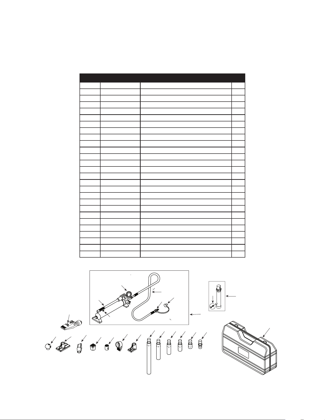
Figure 4 - Replacement Parts Illustration for Model BRK4T
REPLACEMENT PARTS
Not all components of the jack are replacement items, but are illustrated as a convenient reference of location and
position in the assembly sequence. When ordering parts, give Model number, serial number and description below.
Call or write for current pricing: Matco Tools 4403 Allen Road, Stow, OH 44224-1096, U.S.A.
Tel:(866)BUY-TOOL Matco Tools Website: http://www.matcotools.com
8
Model BRK4T
1
20
3
18
17 16
15
14 13
12
11
4
10
9
8
7
6
5
2
21
19
23
22
24
Item Part No. Description Qty
1 F040-90211-K01 Pump Assembly 1
2 F040-90009-K06 Ram Assembly 1
3 F040-22000-000 Hose Assembly (with coupler) 1
4 F040-00001-000 Blow Molded Case 1
5 F040-42000-000 Hydraulic Spreader (1000 lb. capacity) 1
6 F040-40002-000 Combination Head 1
7 F040-43000-000 Rubber Head 1
8 F040-40004-000 Ram Toe 1
9 F040-40005-000 Plunger Toe 1
10 F040-44000-000 Flat Base 1
11 F040-40003-000 Serrated Saddle 1
12 F040-40001-000 Wedge Head 1
13 F040-41600-000 Male connector 1
14 F040-41400-000 Extension Tube (3") 1
15 F040-41300-000 Extension Tube (6-1/8") 1
16 F040-41200-000 Extension Tube (8-1/2") 1
17 F040-41100-000 Extension Tube (16-1/2") 1
18 F040-41500-000 Extension Tube (19-1/2") 1
19 F040-22200-000 Release Valve Knob 1
20 F040-90009-K04 Ram Coupler Assy, Female 1
21 F040-20012-000 Dust Cover - Hose 1
22 F040-90009-K03 Pump Handle 1
23 F040-90107-K02 Oil Filler Screw 1
24 F100-80001-000 Gauge 1
- F0400S-85 Repair Kit -
- BRK4T-L0 Label 1
- BRK4T-M0 Manual 1
9
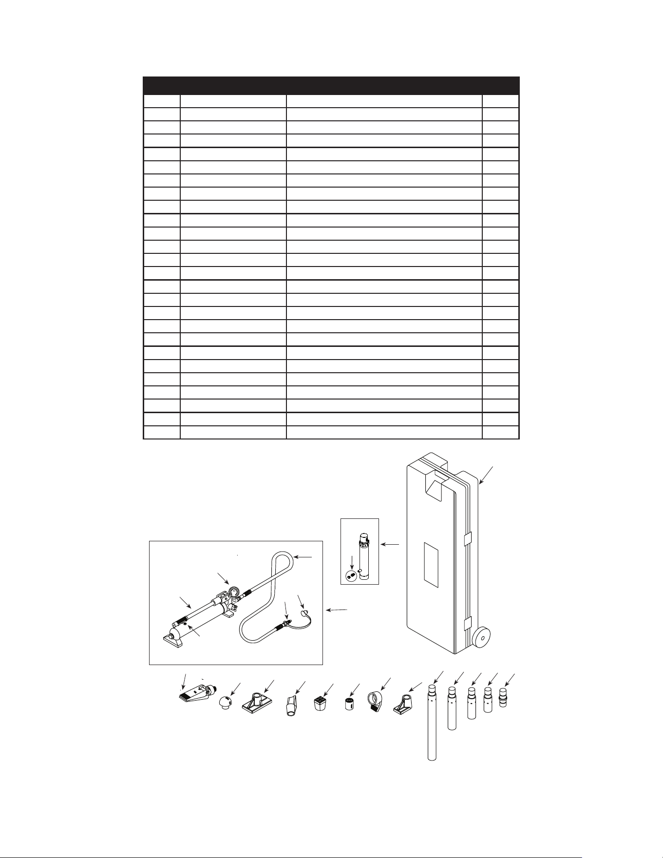
Figure 5 - Replacement Parts Illustration for Model BRK10T
Model BRK10T
1
3
17
16
15 14
13
12
11
10
4
9
8
7
6
5
2
21
19
18
22
⒀⑾⑥⑾⒀⒆
⑩㈢
23
20
Item Part No. Description Qty
1
F100-90211-K01
Pump Assembly 1
2 F100-30000-000 Ram Assembly 1
3 F040-22000-000 Hose Assembly 1
4 F100-00004-000 Blow Molded Case 1
5 F040-42000-000 Hydraulic Spreader (1000 lb. capacity) 1
6 F100-40003-000 Combination Head (90
o
) 1
7 F100-42000-000 Rubber Head 1
8 F100-40005-000 Ram Toe (offset) 1
9 F100-40006-000 Plunger Toe (offset) 1
10 F100-40001-000 Flat Base 1
11 F100-40004-000 Serrated Saddle 1
12 F100-40002-000 Wedge Head (offset) 1
13 F100-41500-000 Male Connector 1
14 F100-41400-000 Extension Tube (4") 1
15 F100-41300-000 Extension Tube (10") 1
16 F100-41200-000 Extension Tube (18") 1
17 F100-41100-000 Extension Tube (27") 1
18 F040-90107-K02 Oil Filler Screw 1
19 F040-90009-K05 Hose Coupler, Male 1
20 F040-90009-K04 Ram Coupler Assy, Female 1
21 F040-20012-000 Dust Cover - Hose 1
22 F100-90009-K01 Pump Handle 1
23
F100-80001-000 Gauge
1
- F1000S-85 Repair Kit -
- BRK10T-L0 Label ( not shown) 1
- BRK4T-M0 Manual 1

10
LOAD - PRESSURE CORRELATION CHART
Models BRK4T & BRK10T
Always monitor the force applied to work piece by using a load cell and indicator or you may monitor pressure
developed in the ram by using an in-line pressure gauge, then calculate the applied force using the formula:
F = P x A
where F = Force/ Load (lbs)
P = Hydraulic Working Pressure (psi) and
A = Ram Effective Area (in²)*
Load
(lbs)
Pressure (psi) of 4 Ton
Ram, where A = 0.998 in
2
Pressure (psi) of 10 Ton
Ram, where A = 2.411 in
2
1,000 1,002 415
2,000 2,004 830
3,000 3,006 1,244
4,000 4,008 1,659
5,000 5,010 2,074
6,000 6,012 2,489
7,000 7,014 2,903
8,000 8,016 3,318
9,000 3,733
10,000 4,148
11,000 4,562
12,000 4,977
13,000 5,392
14,000 5,807
15,000 6,221
16,000 6,636
17,000 7,051
18,000 7,466
19,000 7,881
20,000 8,295
*For Model BRK4T, A = 0.998 in²; For Model BRK10T, A = 2.411 in²
Example 1
Model BRK4T exerting 5,000 lbs of force will require what pressure?
Pressure = Force / Ram Effective Area = 5,000 lbs / 0.998 in² = 5,010 psi
Example 2
Model BRK10T operating at 6,000 psi will generate what force?
Force = Pressure x Ram Effective Area = 6,000 psi x 2.411 in
2
= 14,466 lbs

11
Matco Tools
4403, Allen Road, Stow, OH 44224-1096, U.S.A.
Tel: (866) BUY-TOOL
Matco Website: http://www.matcotools.com

12
Matco Tools
4403, Allen Road, Stow, OH 44224-1096, U.S.A.
Tel: (866) BUY-TOOL
Matco Website: http://www.matcotools.com
ONE YEAR LIMITED WARRANTY
For a period of one (1) year from date of purchase, Matco Tools will repair or replace, at its option, without
charge, any of its products, which fails due to a defect in material or workmanship under normal usage. This limited
warranty is a consumer's exclusive remedy.
Performance of any obligation under this warranty may be obtained by returning the warranted product,
freight prepaid, to Matco Tools Warranty Service Department, 4403 Allen Road, Stow, OH 44224-1096.
([FHSW ZKHUH VXFK OLPLWDWLRQV DQG H[FOXVLRQV DUH VSHFL¿FDOO\ SURKLELWHG E\ DSSOLFDEOH ODZ 7+(
CONSUMER'S SOLE AND EXCLUSIVE REMEDY SHALL BE THE REPAIR OR REPLACEMENT OF DEFECTIVE
PRODUCTS AS DESCRIBED ABOVE. (2) Matco Tools SHALL NOT BE LIABLE FOR ANY CONSEQUENTIAL
OR INCIDENTAL DAMAGE OR LOSS WHATSOEVER. (3) ANY IMPLIED WARRANTIES, INCLUDING WITHOUT
LIMITATION THE IMPLIED WARRANTIES OF MERCHANTABILITY AND FITNESS FOR A PARTICULAR
PURPOSE, SHALL BE LIMITED TO ONE YEAR, OTHERWISE THE REPAIR, REPLACEMENT OR REFUND AS
PROVIDED UNDER THIS EXPRESS LIMITED WARRANTY IS THE EXCLUSIVE REMEDY OF THE CONSUMER,
AND IS PROVIDED IN LIEU OF ALL OTHER WARRANTIES, EXPRESS OR IMPLIED. (4) ANY MODIFICATION,
ALTERATION, ABUSE, UNAUTHORIZED SERVICE OR ORNAMENTAL DESIGN VOIDS THIS WARRANTY AND
IS NOT COVERED BY THIS WARRANTY.
Some states do not allow limitations on how long an implied warranty lasts, so the above limitation may not
apply to you. Some states do not allow the exclusion or limitation of incidental or consequential damages, so the
DERYHOLPLWDWLRQRUH[FOXVLRQPD\QRWDSSO\WR\RX7KLVZDUUDQW\JLYHV\RXVSHFL¿FOHJDOULJKWVDQG\RXPD\DOVR
have other rights, which vary from state to state.