1
NOTICE TO THE USER:
IF YOU NEED ASSISTANCE
CONNECTING THIS NATURAL
GAS CONVERSION KIT TO
YOUR SERVICE, CONTACT
A LOCAL CERTIFIED GAS
PLUMBER TO ENSURE IT HAS
SAFELY BEEN CHANGED &
TESTED.
WARNING
MODEL NO: QG-2186
Propel+ Natural Gas Conversion Kit
DO NOT RETURN PRODUCT TO THE STORE
Before visiting your local retailer, please email
[email protected] or call our customer service
department at 1-866-994-6390 to chat with a representative.
To best serve you, our representatives are available to answer
calls Monday to Friday 9 AM to 5 PM EST.
Customer Service Hotline
1-866-994-6390
Outdoors
2
Table of Contents
Table of Contents 2
Safety Information 3
What’s In The Box 4
Assembly Instructions 5
Operating Instructions 16
Use and Care 19
Warranty & Replacement Parts Back Cover
3
SAFETY INFORMATION
Read Product Manual Guide completely before assembling the Propel+ 3-in-1 Propane
Gas Grill Model: (CGG-6331 & CGG-63311). Failure to follow instructions and safety
precautions in this guide could cause serious injury or property damage.
This product is for outdoor use only.
Place grill on a flat, level surface before
starting the conversion.
We recommend that you hire a qualified
technician to install this Natural Gas
Conversion Kit. Incorrect installation may
result in explosion and serious injury.
This conversion kit can be installed by a qualified
service agency if you so choose in accordance with
the manufacturer’s instructions and all applicable
codes and requirements of the authority having
jurisdiction. If the information in these instructions
is not followed exactly, a fire, an explosion, or
production of carbon monoxide can result, causing
property damage, personal injury, or loss of life. The
installation is not complete until the operation of the
converted appliance is checked as specified in the
manufacturer’s instructions supplied in this manual.
Risk of cancer from exposure to Carbon
Monoxide and reproductive harm from
Carbon Monoxide.
See www.P65Warnings.ca.gov
WARNING
WARNING
WARNING
WARNING
NOTE: Damage to grill as a result of incorrect conversion to natural gas is not covered by the grill or the
conversion kit warranty.
1. The outdoor cooking gas appliance must be isolated from the gas supply piping system by closing its individual
manual shut-off valve during any pressure testing of the gas supply piping system at test pressures equal to or less
than 1/2 psi (3.5 kPa).
2. WARNING: This NG conversion kit can only be installed to convert your Cuisinart Propel+ propane grill to natural
gas, follow the steps carefully by the manufacture. If you feel unsure or uncomfortable at any point, it’s best to
consult a licensed professional gas plumber. Safety is paramount when working with gas appliances, so if you have
any doubts about any part of the conversion process, seek professional assistance by a qualified gas service
company in accordance with the manufacturer’s instructions and all applicable codes and requirements of the
authority having jurisdiction. If the information in these instructions is not followed exactly, a fire, an explosion or
production of carbon monoxide can result, causing property damage, personal injury, or loss of life.
3. CURRENT - MODEL FOR THIS KIT:
Model CGG-6331 : Propel+ 3-in-1,
4-Burner
Grill performance on Liquid Propane Gas
Main Burner: 4 x 11,000 BTU/HR
Side Burner: 11,000 BTU/HR
Total Input Rating: 55,000 BTU/HR
4
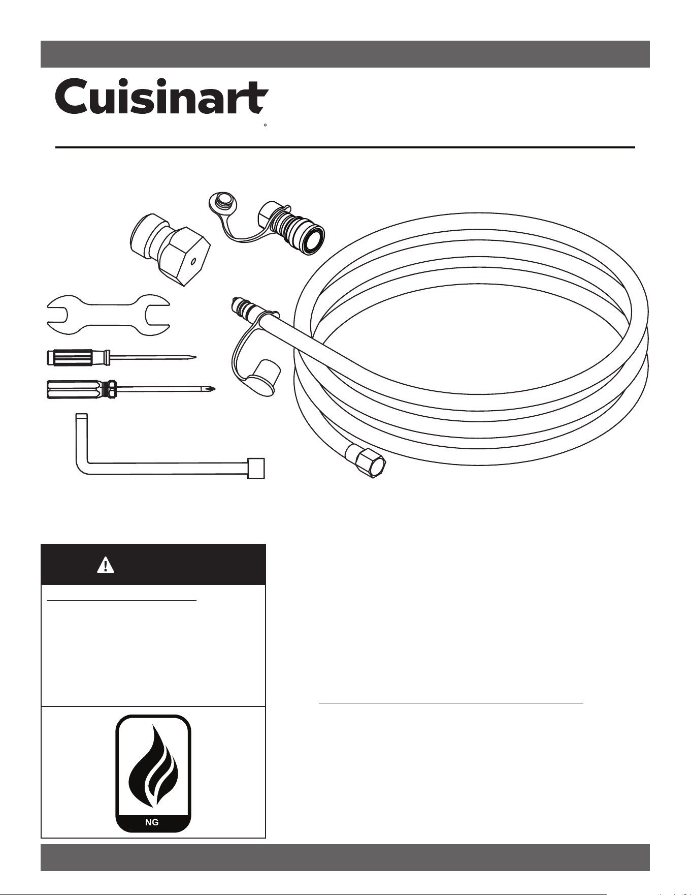
Before beginning assembly, installation or operation of product, make sure all parts are present. Compare parts
with the “what’s in the box” list. If any part is missing or damaged, do not attempt to assemble, install or operate
the product. Contact customer service for replacement parts.
Estimated assembly time:
1-hour or less to change
Tools you will need:
• NG Valve Kit Tools
(included)
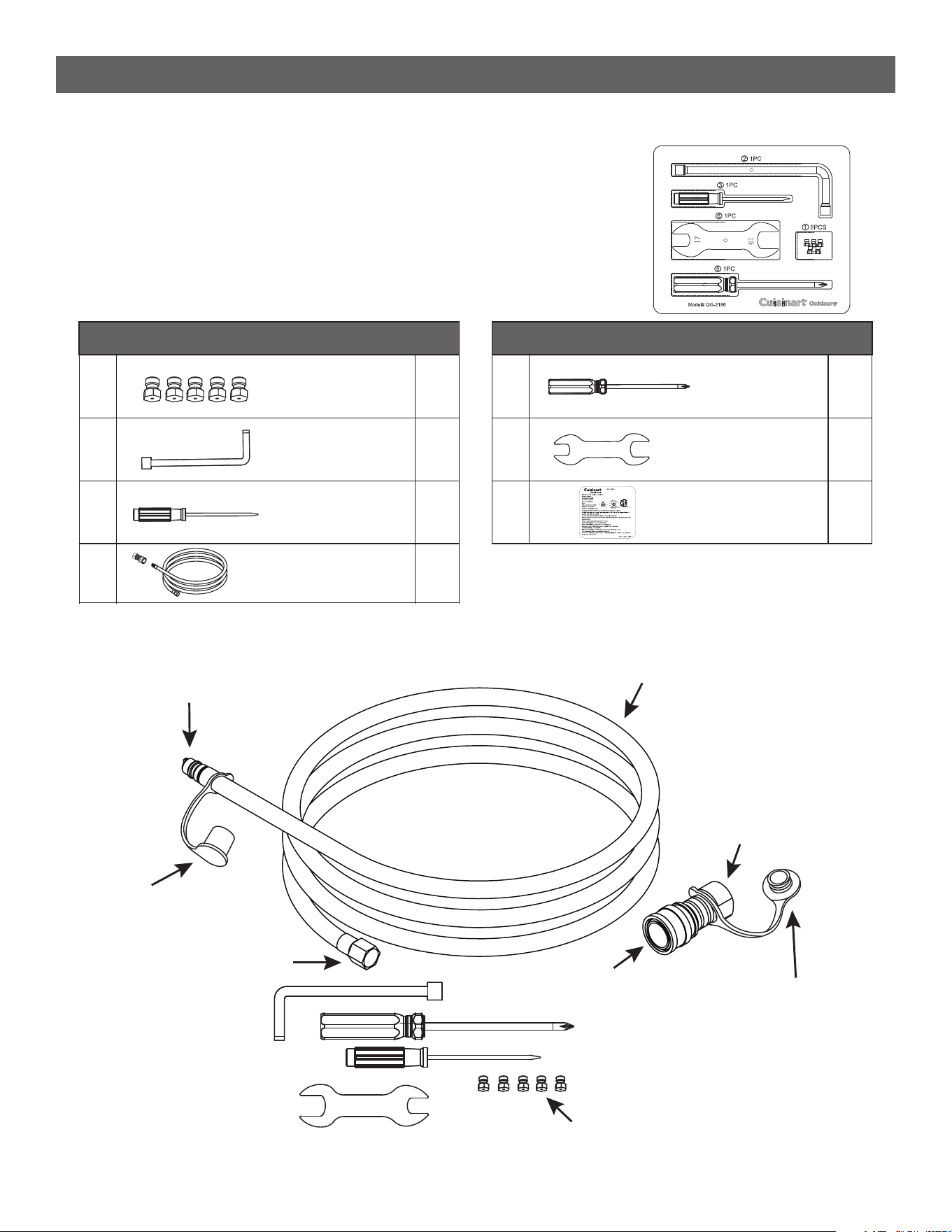
WHAT’S IN THE BOX
Orifice 1.34mm
Orifice Removal
Tool
1
Slotted
Screwdriver
5
1
2
3
1
4
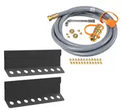
10ft. Hose & Quick
Disconnect Socket
1
PART PARTS DESCRIPTION QTY
Phillips
Screwdriver
Wrench
17mm-19mm
5
1
6
NG Label
1
7
1
PART PARTS DESCRIPTION QTY
12.5 mm (1/2”) x 10 Feet
Diameter Braided Flex Hose
1/2” Female
Pipe Thread
(NPT)
1/2” Female
Quick Connect
1/2” Female Flare
1/2” Male Quick
Disconnect
Male Disconnect
All-Weather Cover
Female Quick
Disconnect
All-Weather
Cover Plug
1.34mm Orifice Nozzle
5
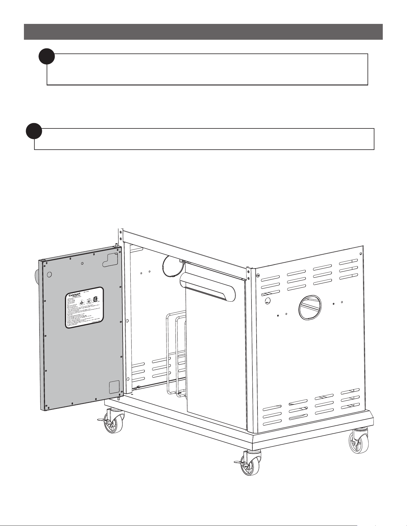
ASSEMBLY INSTRUCTIONS
STEP 1
--------------------------------------------------------------------------------------
• Paste the new NG label ( 7 ) over the original LP rating label that is adhered to the left side door of grill.
Natural Gas Conversion Instructions:
!
Note: When you open the package, consult the manual to ensure that there are no missing or
damaged parts. If anything is missing, please contact our customer service department at
866-994-6390 9am to 5pm EST Monday – Friday or email us at: [email protected]
!
Note: Before converting to natural gas, ensure that the propane tank is removed, with ALL knobs in
the OFF position and the cylinder valves are closed.
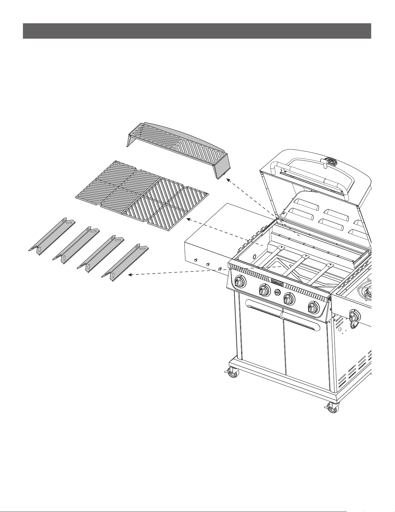
6
STEP 2
--------------------------------------------------------------------------------------
• Open grill lid.
• Remove the Warming Rack, both Grill Grates, and Flame Tamers and carefully place aside.
ASSEMBLY INSTRUCTIONS
7
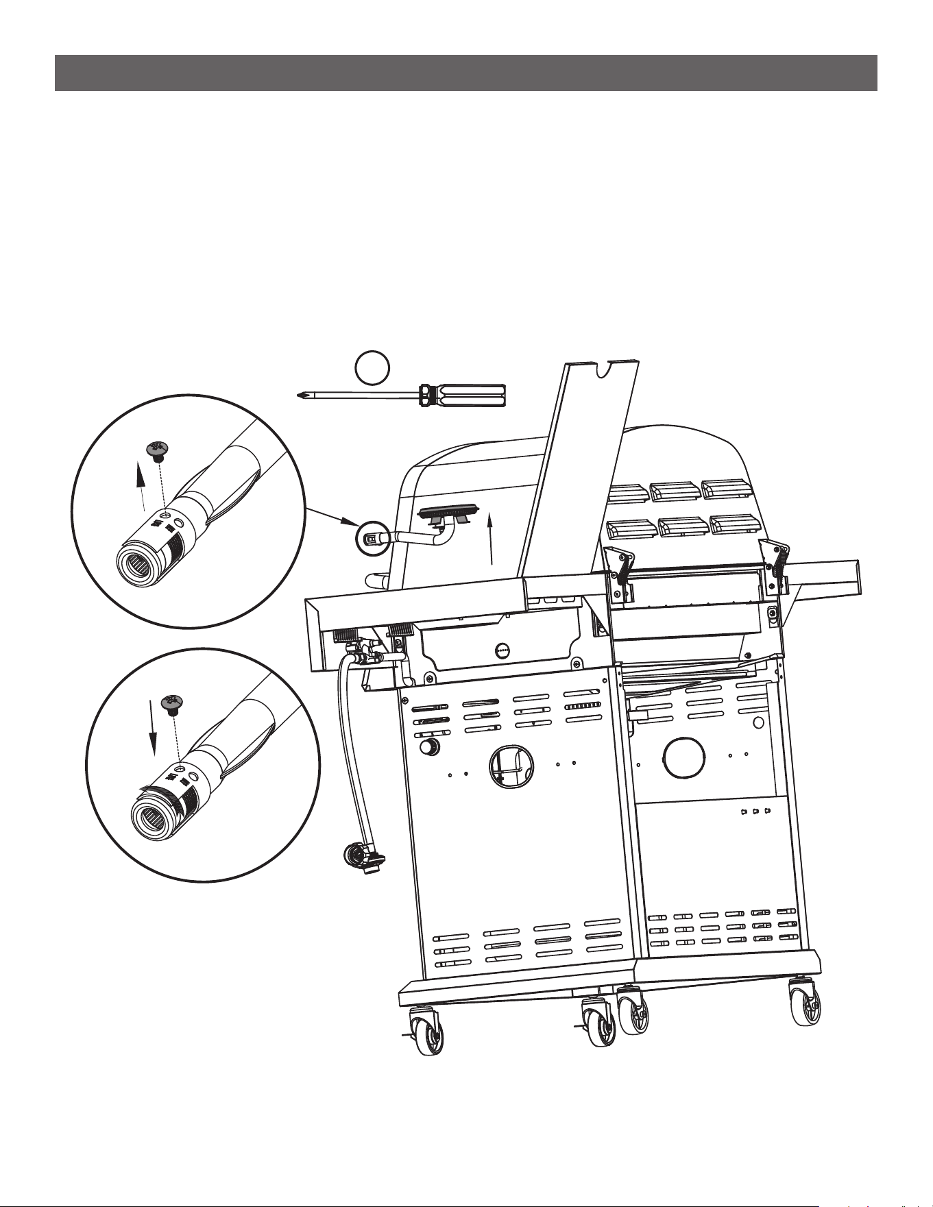
ASSEMBLY INSTRUCTIONS
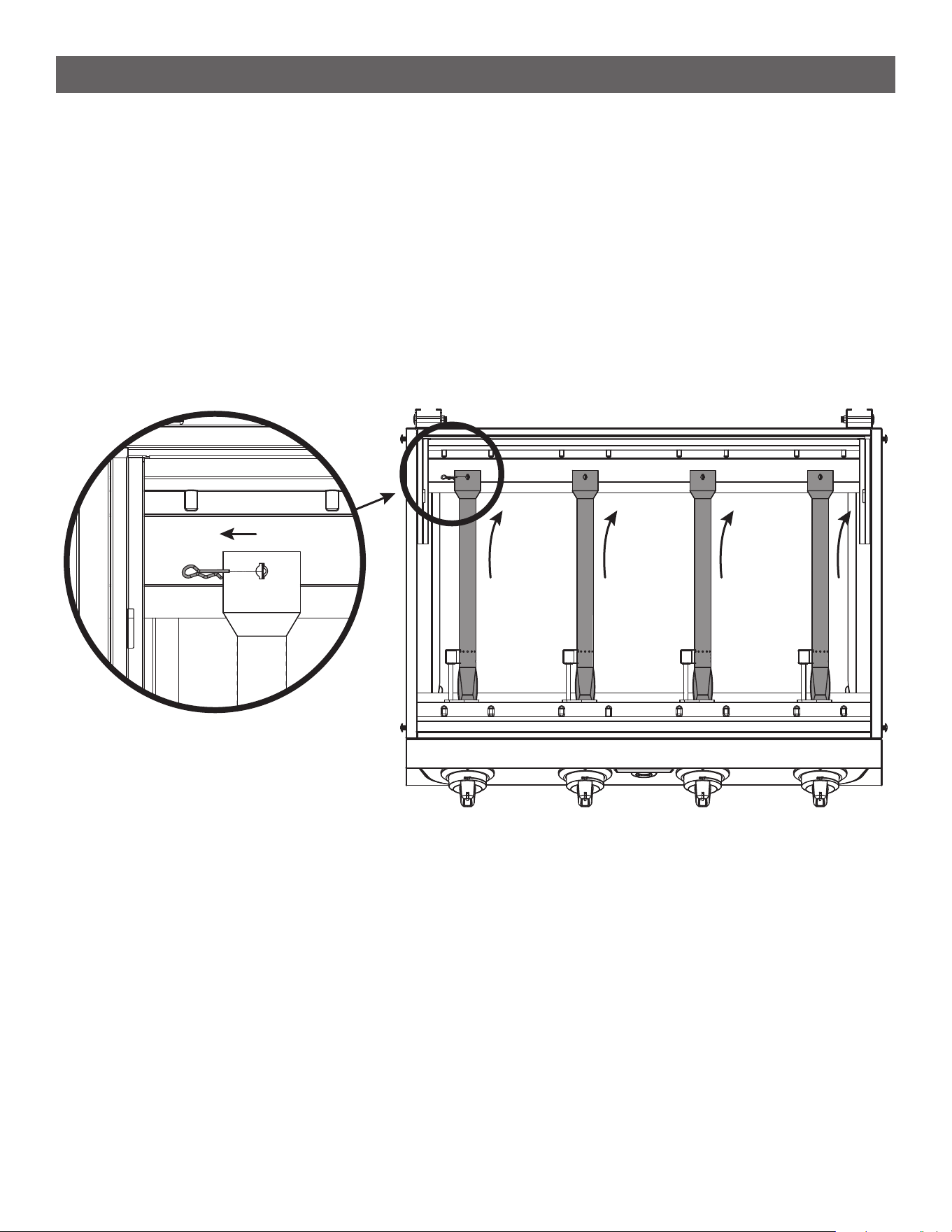
STEP 3
--------------------------------------------------------------------------------------
• Remove the cotter pins at the back of the 4 main burners [ l ].
• Lift burners off the back post in the firebox. Then slide burner tube backwards a few inches to allow tube to
disengage from the burner gas valves. [ II ]. (Note: Do not fully remove the burners from the firebox as an
ignition wire is connected to each tube. **Do not disconnect wire**.
• Set the burner tube down inside the firebox. Do the same to the remaining 3 burner tubes.
[ ll ]
[ l ]
8
ASSEMBLY INSTRUCTIONS
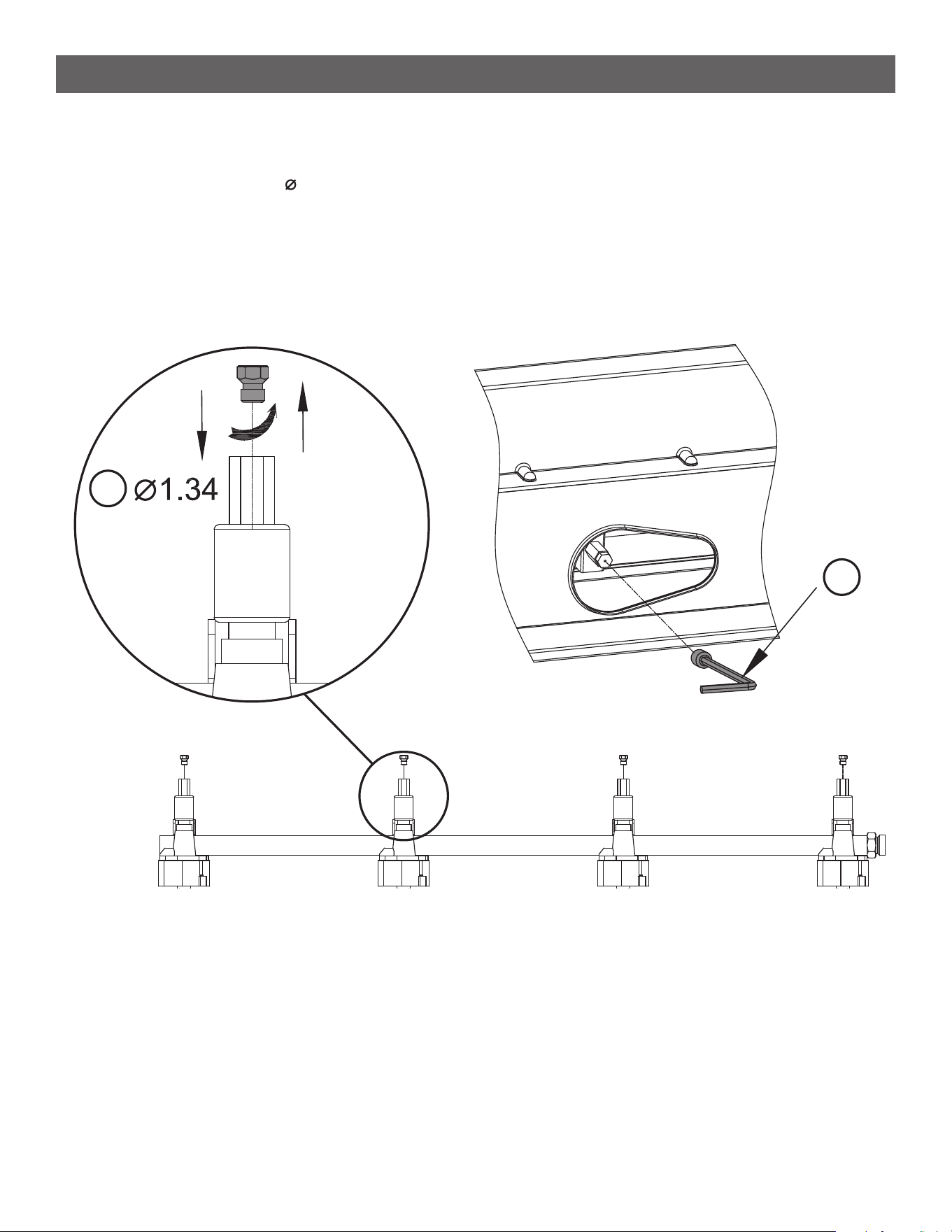
STEP 4
--------------------------------------------------------------------------------------
• Unscrew the old LP orifice from each gas valve with the orifice removal tool ( 2 ).
• Put a new NG orifice ( 1 ) [ 1.34] into the valve and tighten with tool ( 2 ). Repeat this step for all four main
burners.
[ ll ] [ l ]
1
2
9
ASSEMBLY INSTRUCTIONS
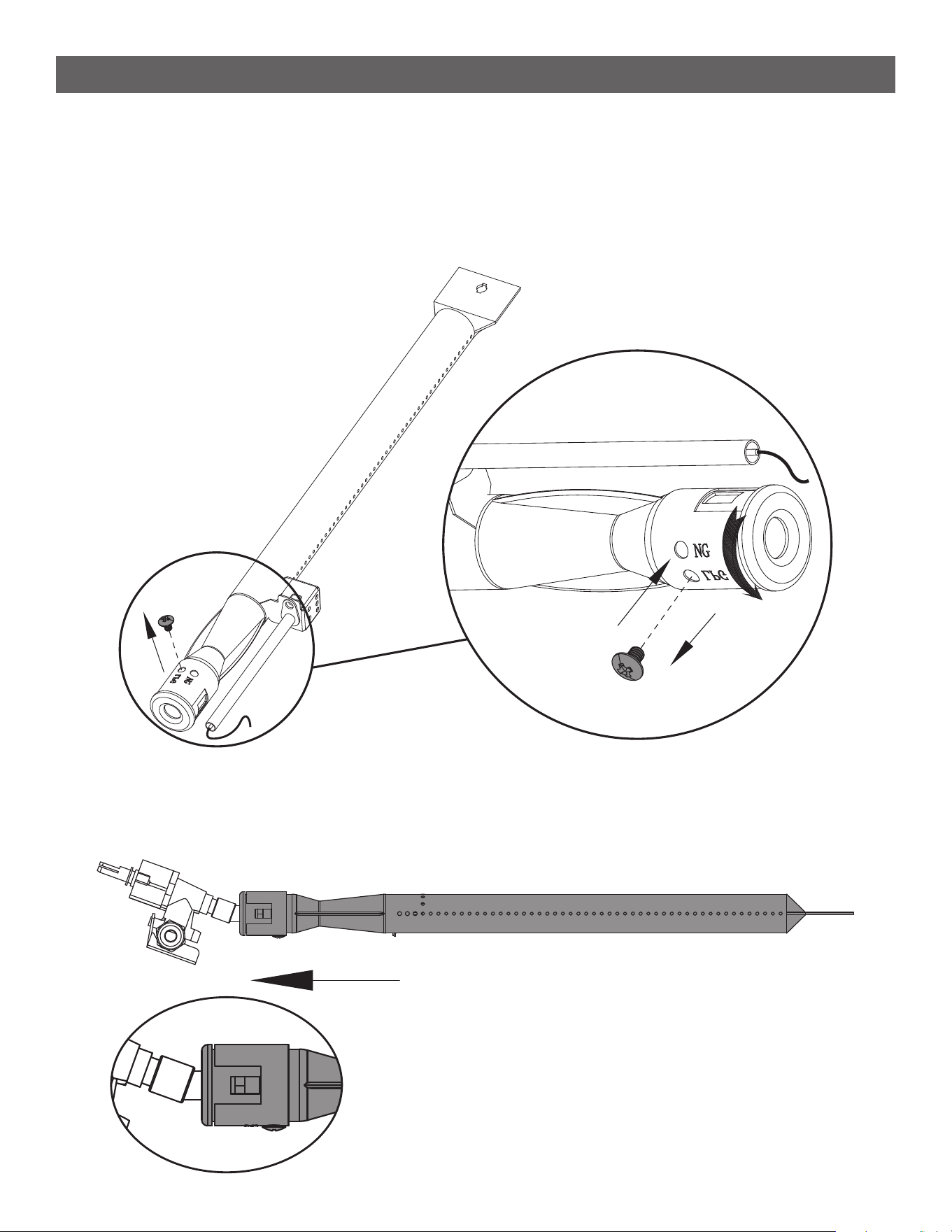
STEP 5
--------------------------------------------------------------------------------------
• Use the Phillips screwdriver supplied in the parts kit ( 5 ) to unscrew the M4 screw from each main burner
as shown [ l ].
• Rotate the burner air shutter opening counterclockwise, adjusting it from the LP setting to the NG
setting [ ll ].
• Replace and tighten the M4 screw to secure the air shutter opening in place [ lll ].
STEP 6
--------------------------------------------------------------------------------------
• Reinstall each of the four main burners and secure with previously removed cotter pin. Make sure to
engage each burner over the gas valve as shown.
[ ll ]
[ lll ]
[ l ]
10
ASSEMBLY INSTRUCTIONS
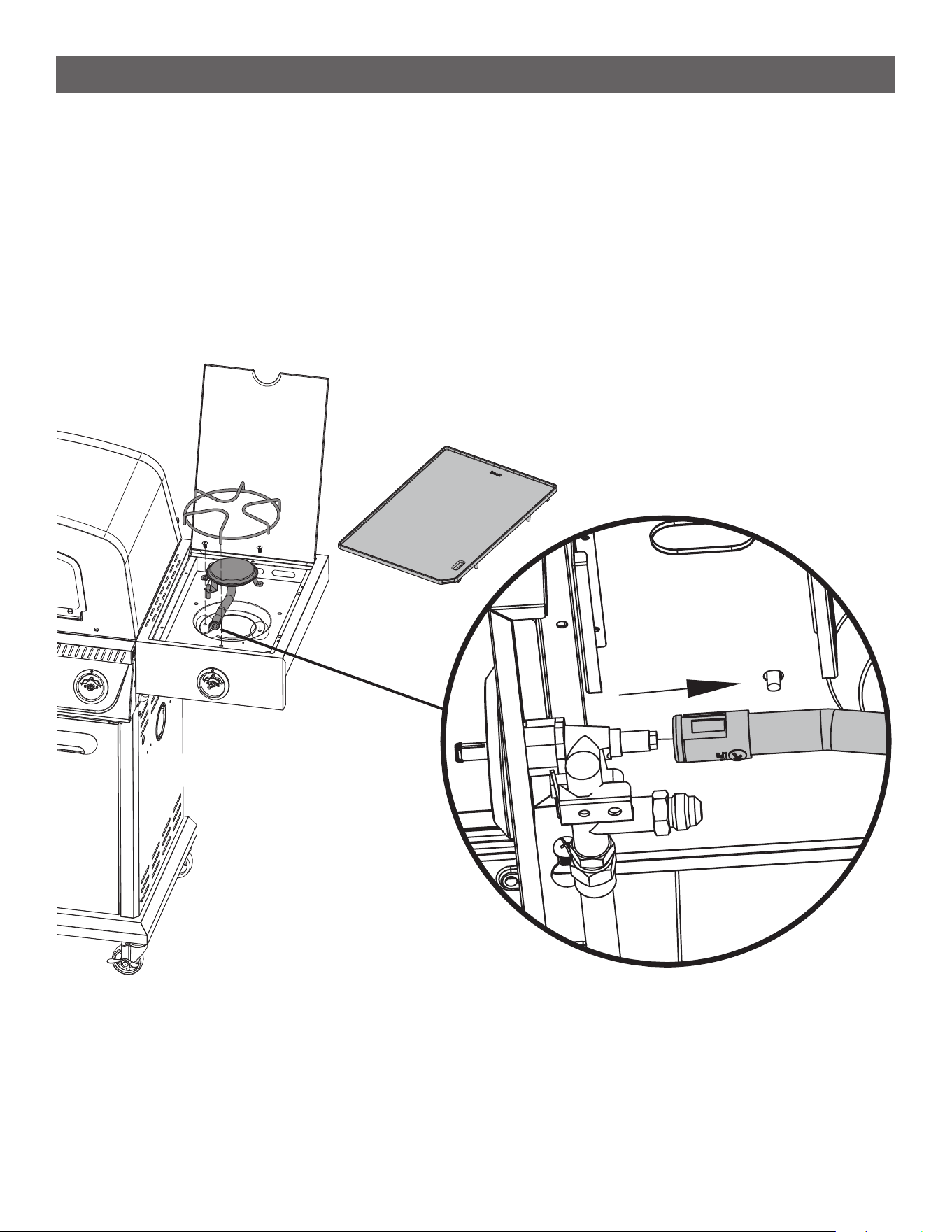
STEP 7
--------------------------------------------------------------------------------------
• Open side burner lid. Remove the Griddle plate and the Wire Rack for pots and set aside.
• Unscrew the 2 screws holding down the round burner and pull backwards and upwards valves as shown
and set aside.
• Note: The round burner tube has an ignition wire connected on the underside, it is recommended to leave
that wire connected and just keep the round burner on the top of the side table for now and save both
screws to reinstall.
11
STEP 8
--------------------------------------------------------------------------------------
• Use the Phillips screwdriver supplied in the parts kit ( 5 ) to unscrew the 2 screws under the side burner,
and take out the side burner.
• Use the Phillips screwdriver ( 5 ) to unscrew the M4 screw from the side burner as shown [ l ].
• Rotate the burner air shutter opening counterclockwise, adjusting it from the LP setting to the NG
setting [ ll ].
• Replace and tighten the M4 screw to secure the air shutter opening in place [ lll ].
ASSEMBLY INSTRUCTIONS
5
[ l ]
[ lll ]
[ ll ]
12
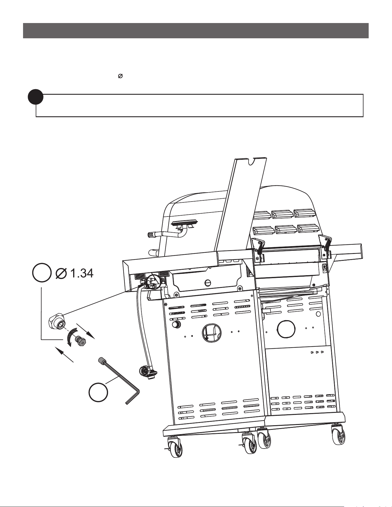
ASSEMBLY INSTRUCTIONS
STEP 9
--------------------------------------------------------------------------------------
• Unscrew the old LP orifice from the gas valve with the orifice removal tool ( 2 ).
• Put a new NG orifice ( 1 ) [ 1.34] into the valve [ lll ] and tighten with tool ( 2 ).
[ ll ]
[ lll ]
1
2
!
Note: Your grill may have a white sealant on the end of the burner valve orifice. When changing to
the NG nozzles, it is not required to add any sealant to the orifice threads.
13
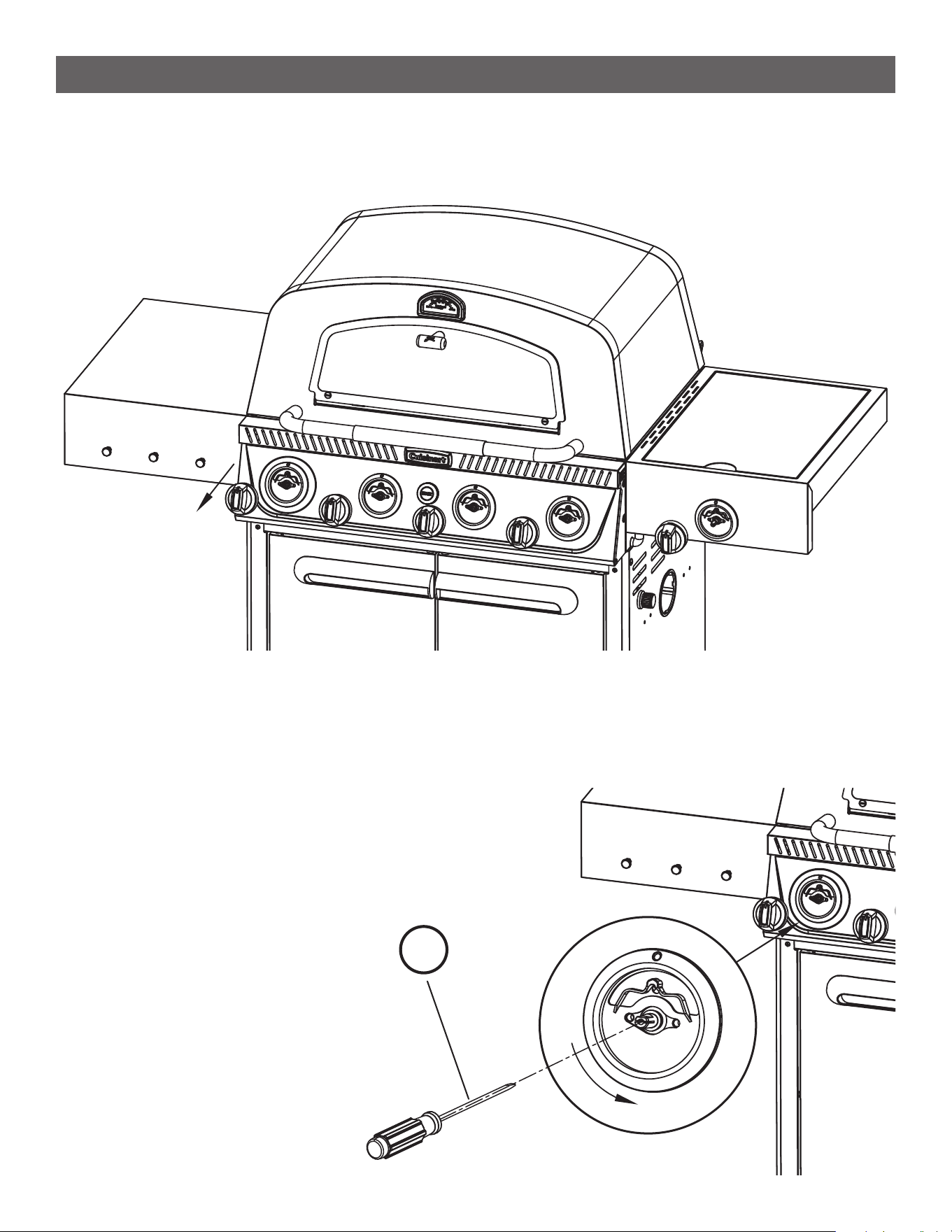
ASSEMBLY INSTRUCTIONS
STEP 10
--------------------------------------------------------------------------------------
• Remove all five control knobs by pulling them off the valve stem [ l ].
STEP 11
--------------------------------------------------------------------------------------
• Insert the supplied flathead screwdriver ( 3 ) into the hole of one of the five control valve stem as shown.
• Rotate the screw inside the center of each stem counterclockwise
as far as it will go (about 2 complete turns) until it stops [ ll ].
The valve will now be set in the NG position.
• Do this same step on the on the remaining three main burners
on the control panel plus the one side burner.
[ l ]
[ ll ]
3
14
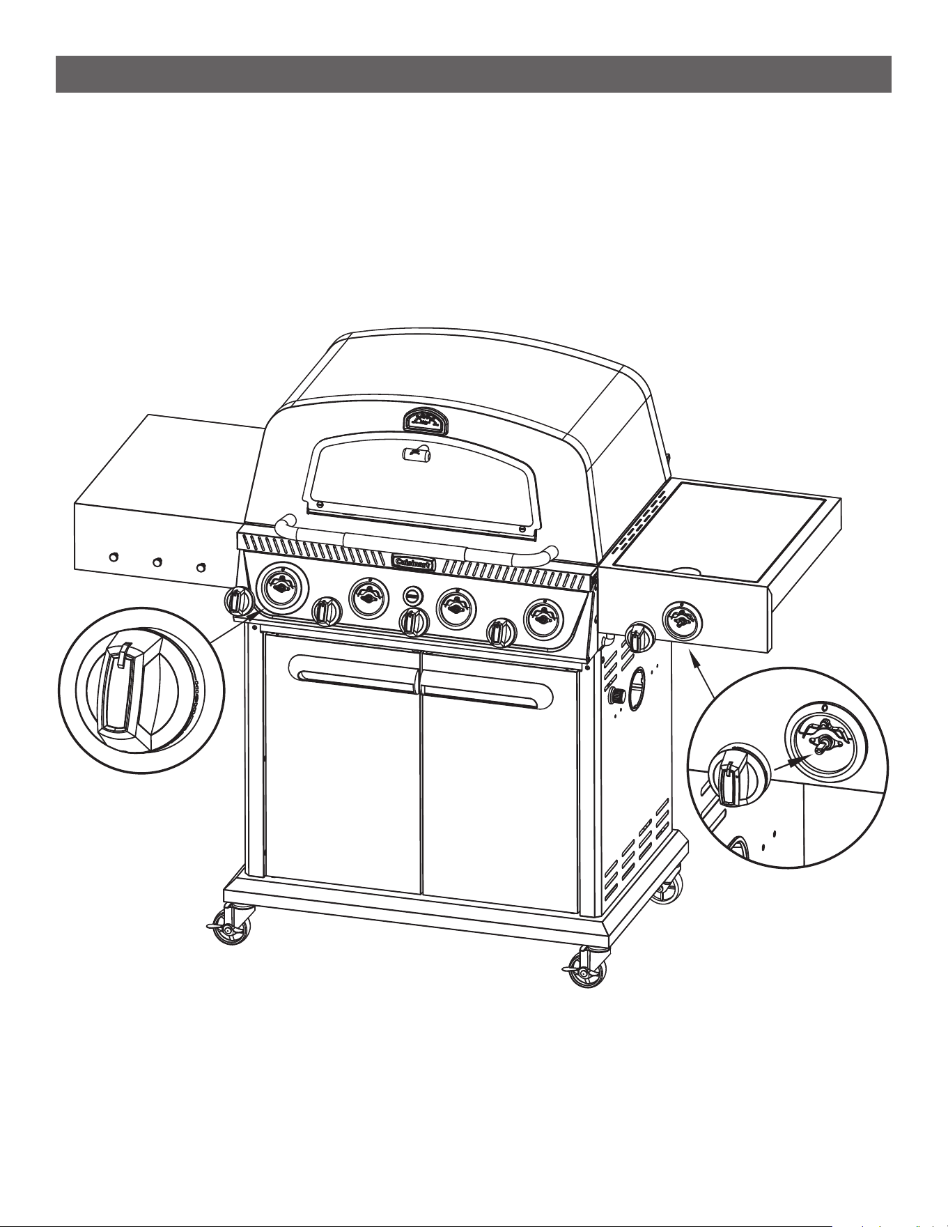
ASSEMBLY INSTRUCTIONS
STEP 12
--------------------------------------------------------------------------------------
• Reattach the four main burners and the one side burner control knobs by lining up the D-shape slot onto
the D-shaped stem and push in.
15
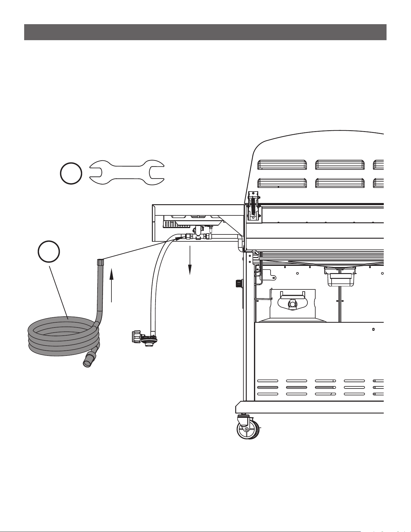
ASSEMBLY INSTRUCTIONS
STEP 13
--------------------------------------------------------------------------------------
• Use the wrench ( 6 ) to detach the LP regulator and hose from threaded fitting as shown [ l ].
• Replace with the NG hose ( 4 ) and use the wrench ( 6 ) to re-attach threaded end nut and tighten
snug [ ll ].
[ ll ]
[ l ]
6
4
16
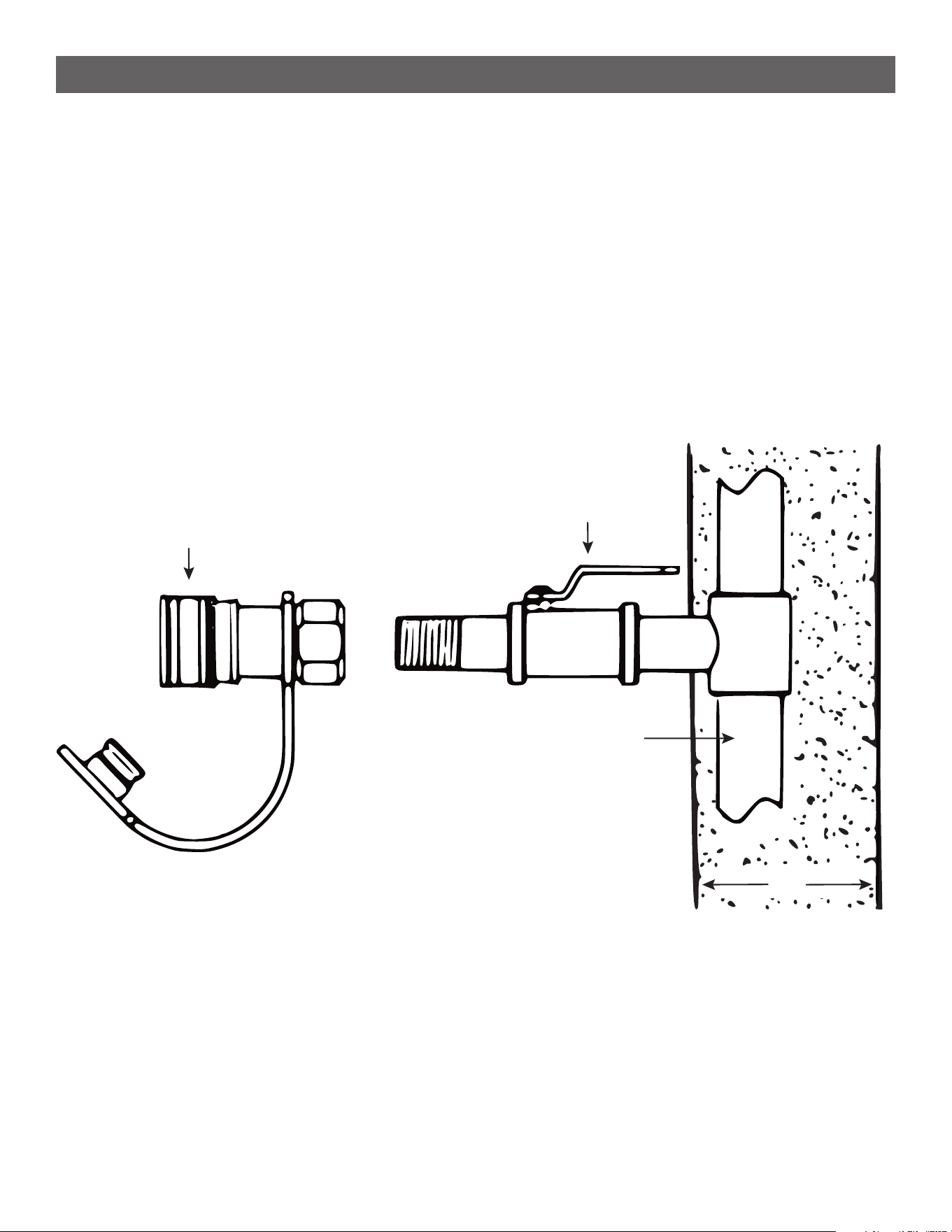
CONNECTION TO NATURAL GAS SUPPLY
Natural Gas Connection:
• IMPORTANT: When connecting or replacing gas pipe or fittings, all joints must be sealed with
approved leak-proof sealing compound or plumber’s tape. After making connections, pressurize
the system, then check all joints for leaks using a soapy water solution and a brush.
• Connect a Manual Shut-Off Valve to the gas supply line. Connect the Quick Disconnect Socket to the
Manual Shut-Off Valve at the gas supply. An easily available Manual Shut-Off Valve must be installed
upstream of and as close to the Quick Disconnect as possible.
• WARNING: The Quick Disconnect Socket must not be installed in an upward direction.
Quick Disconnect Socket
Manual Shut-Off Valve
(House) Natural Gas Piping
Wall
17
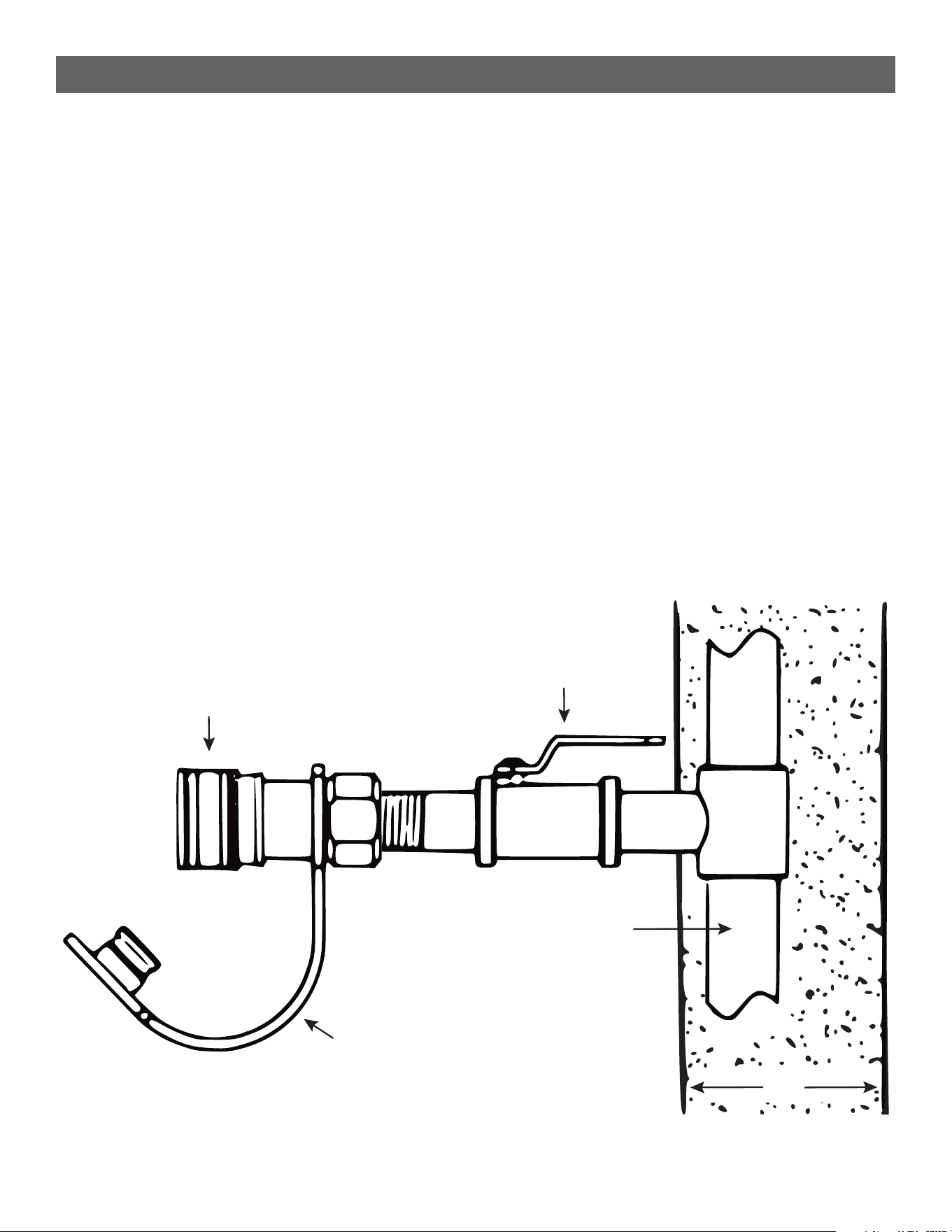
CONNECTION TO NATURAL GAS SUPPLY
CONNECTING THE GRILL TO THE NATURAL GAS SUPPLY
--------------------------------------------------------------------------------------
• The Quick Disconnect Socket and supply gas line must be installed by a qualified technician. The supply
connection must be made in accordance with local codes or, in the absence of local codes, with either the
National Fuel Gas Code, ANSI Z223.1/NFPA 54, in the USA, of the Natural Gas and Propane Installation
Code, CSA B149.1, in Canada. A properly sized manual shut-off valve must be installed between the grill
and the gas supply piping. The grill and its individual shut-off valve must be disconnected, check safety
valve from the gas supply piping system.
• The grill must be isolated from the gas supply piping system by closing its individual manual shut-off valve
during any pressure testing of the gas supply piping system at test pressures equal to or less than 0.5 PSI
(3.5 kPa).
Quick Disconnect Socket
Manual Shut-Off Valve
(House) Natural Gas Piping
Protective Rubber Cap
Wall
TO CONNECT
--------------------------------------------------------------------------------------
1. Ensure that the natural gas shut-off valve is closed.
2. Remove the protective rubber caps from the plug and sleeve ends of the Quick Disconnect fittings. Check
that the fittings are clean.

18
CONNECTION TO NATURAL GAS SUPPLY
Wall
TO CONNECT (continued)
--------------------------------------------------------------------------------------
3. Retract the sleeve on the coupling as illustrated.
4. Insert the plug and release the sleeve as illustrated.
5. Push the plug into the sleeve until the sleeve snaps forward to lock the plug in the coupling.
6. Open the natural gas shut-off valve.
TO DISCONNECT
--------------------------------------------------------------------------------------
1. Close natural gas supply at shut-off valve.
2. Pull the sleeve back and gently pull out the plug.
3. Replace the protective rubber caps on the plug and sleeve ends of the quick disconnect coupling and snap
into place.
Retract sleeve backwards
Release sleeve to connect
19
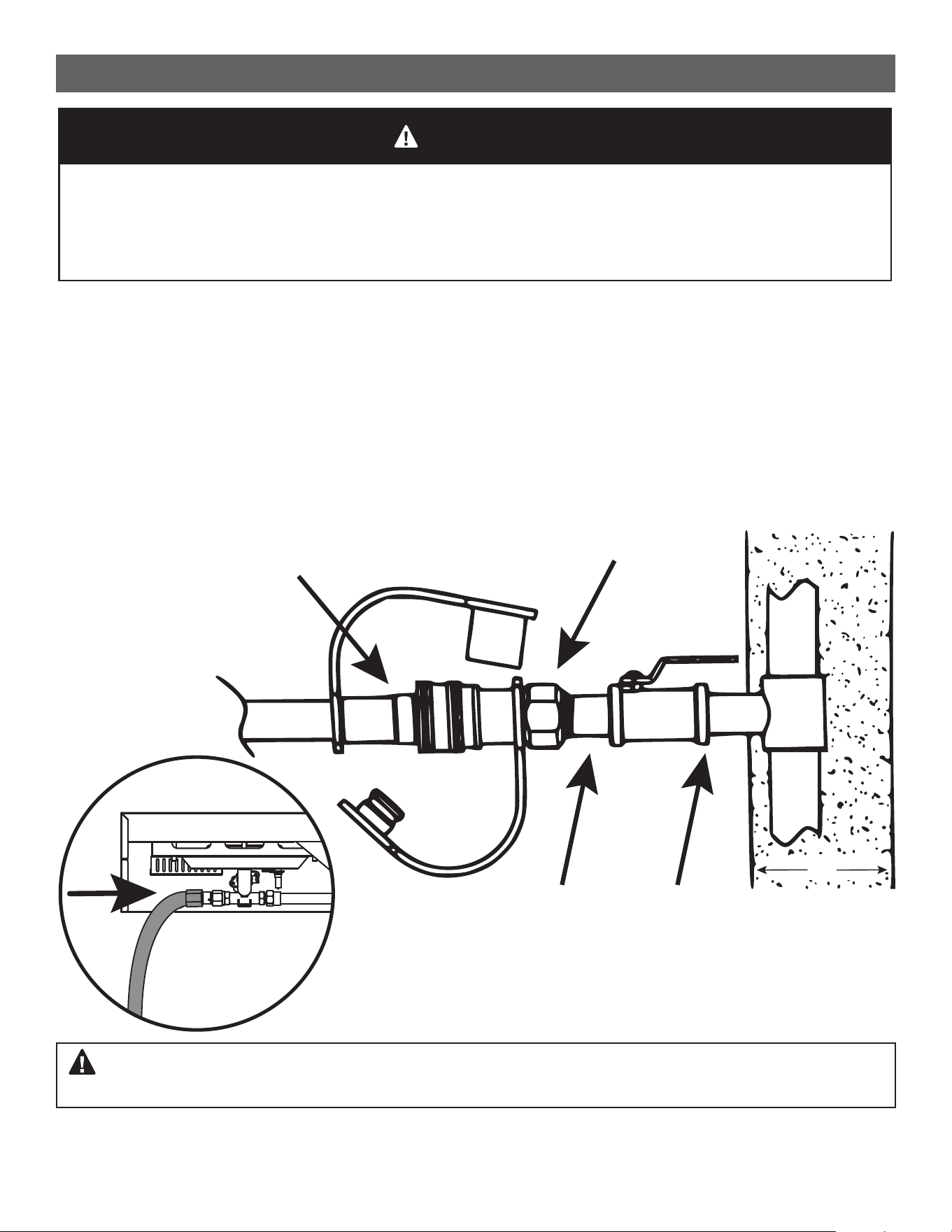
USE AND CARE
CHECKING FOR GAS LEAKS
--------------------------------------------------------------------------------------
1. Make 2-3 ounces of leak-solution by mixing liquid dishwashing soap with water.
2. Be certain all control knobs are in the “OFF” position.
3. Brush small amounts of the solution on all the fittings and turn the gas on.
4. If bubbles appear, there is a leak. Proceed to next steps.
5. Turn the gas off and tighten all connections.
6. If no bubbles appear, there are no leaks. If bubbles do appear, turn the gas valve to OFF. If leak is on the
House Supply side, contact a gas plumber, if leak is on the Quick Disconnect and hose side, please contact
our customer care team service.
7. Go back to Step 1 to retest the fittings. If bubbles continue to appear, turn the gas off. Contact customer
service.
Many areas of an outdoor gas grill generate extreme heat. We have taken every precaution to
protect you from the contact areas. However, it is impossible to isolate all high-temperature
areas. Therefore, use good judgment and caution when grilling on this product. We suggest
a covered, protected hand during operation of grill. Do not move your grill when it is in
operation or hot to the touch. Wait until your unit is turned off and properly cooled down
before moving it. Failure to follow this warning could result in personal injury.
WARNING
Wall
Possible leak areas
• IMPORTANT: When connecting or replacing gas pipe or fittings, all joints must be sealed with
approved leak-proof sealing compound or plumber’s tape. After making connections, check all
joints for leaks using a soapy water solution and a brush.
WARNING: Never use a match or open flame for leak detection. Use of an open flame could result in a fire,
explosion and bodily harm. Never store a spare tank under or near your grill when using Natural Gas fuel.
4

20
Outdoors
Questions, problems, missing parts? Before returning to your retailer,
call our customer service department at 866-994-6390, 9 a.m.-5 p.m.
EST, Monday-Friday or email [email protected]
Visit our website: www.cuisinart.com
2503
Model# QG-2186
Cuisinart Outdoors a division of Conair LLC
Glendale, AZ 85307
WARRANTY AND REPLACEMENT PARTS
• This warranty covers defects in parts and workmanship for a period of 3 years from the original purchase date.
• Any damage claim regarding the enameling must be submitted within 30 days of purchase to be covered by
the warranty.
The following conditions are NOT covered by this warranty:
• Unevenness and color variations in the coated surfaces.
• Damage caused by improper assembly or disregard of the manual.
• Use of spare parts not supplied by manufacturer.
• Damage resulting from modifications or inappropriate use.
• Abuse of the grill.
• Damage caused by improper maintenance or repairs by an unauthorized person.
Limitations and exclusions:
• This warranty applies only to the original purchaser and may not be transferred.
• If you can not verify the purchase date of the grill the warranty period will begin on the date the grill was
manufactured.
• Replacement or repair parts are warranted for the remaining period of the original part warranty.
Your obligations:
• This grill must be assembled, installed, operated and maintained in accordance with all applicable codes and
the instruction manual furnished with this grill. You must keep an invoice, cancelled check or payment record
to verify the purchase date of the grill.