
9b
(4x)
15c
15a
17
9a
(7)
7
8
3c
3b
3a
4
3d
5
6
16
12
2 1
15b
8
11
15a 15b
15c
15
8
11
13
7
8
14
3a 3b
3c 3d
3
9c
(4x)
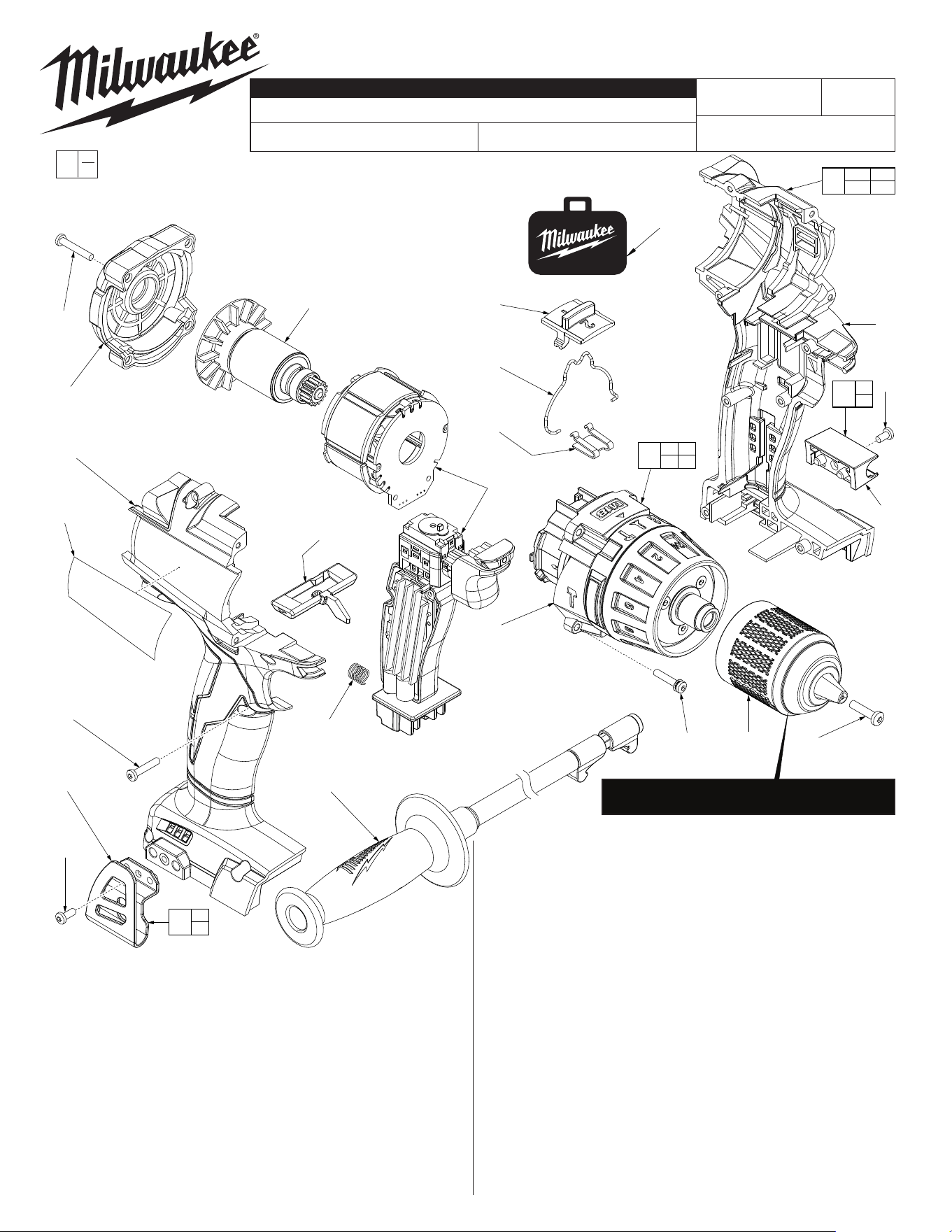
BULLETIN NO.
54-24-2740
SERVICE PARTS LIST
FIG. PART NO. DESCRIPTION OF PART NO. REQ.
1 05-88-0019 M8.0 x 1 LH T-40 Chuck Screw (1)
2 42-66-1006 1/2” Keyless Chuck with Carbide Jaws (1)
3 14-29-0037 Gearbox Assembly (1)
3a 40-50-0021 Detent Spring (1)
3b 45-24-0012 Speed Change Lever (1)
3c 44-10-0014 Speed Selector Slide (1)
3d --------------- Gearbox (1)
4 14-20-0032 Electronics Assembly
Consistsof:On-OSwitch,PCBA,Stator,
LEDAssembly,BatteryConnectorBlock (1)
5 16-07-0041 Rotor Assembly (1)
6 42-42-0052 Forward/Reverse Shuttle (1)
7 --------------- BeltClip (1)
8 06-82-5275 6-32x5/16”PanHd.TaptiteT-15Screw (2)
9a 06-82-6350 M3x16mmPanHd.STT-10Screw (7)
CATALOG NO. 2704-20
REVISEDBULLETIN
SPECIFY CATALOG NO. AND SERIAL NO. WHEN ORDERING PARTS
M18™ FUEL™ Hammer-Drill
STARTING
SERIALNO.
DATE
Feb. 2024
WIRINGINSTRUCTION
G73A
EXAMPLE:
ComponentParts(Small#)AreIncluded
WhenOrderingTheAssembly(Large#).
0
00
SEE PAGE 2
FIG. PART NO. DESCRIPTION OF PART NO. REQ.
9b 06-82-7336 M3x20mmPanHd.STT-10Screw (4)
9c 06-82-7337 M3x20mmPanHd.STT-10SemsScrew (4)
11 --------------- BitHolderwithClip (1)
12 42-62-0010 Side Handle Assembly (1)
13 43-72-0046 BitHolderAssembly (1)
14 42-70-0059 BeltClipAssembly (1)
15 31-44-2703 Housing/End Cap Assembly (1)
15a --------------- Right Housing Halve (1)
15b --------------- Left Housing Halve (1)
15c --------------- End Cap (1)
16 40-50-1090 Compression Spring (1)
17 12-20-0048 ServiceNameplate (1)
18 42-55-0027 BlowMoldedCarryingCase (1)
18
SEE PAGE TWO FOR INSTRUCTIONS ON HOW
TO REMOVE THE CHUCK SCREW AND CHUCK
MILWAUKEE TOOL
l
www.milwaukeetool.com
13135W.LISBONRD.,BROOKFIELD,WI53005
Drwg. 5
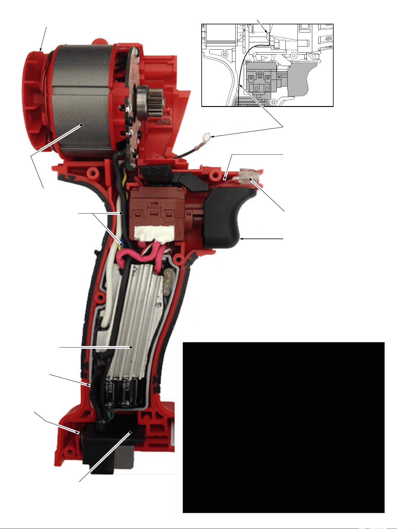
Ground with bottom right gearcase screw
Rotor Assembly
Stator Assembly
with Hall PCBA
High Voltage
Protection
Wire Assembly
LED Assembly
On-Off Switch
Main PCBA
Battery Connector
Block Assembly
Watch for pinched
wires here. Tuck leads
down in cavity behind
switch.
Watch for
pinched
wires here.
Route LED wires
down in cavity
behind forward/
reverse shuttle.
Compression
Spring
REMOVING THE CHUCK SCREW:
Set the Speed Selector Slide (3a) to the #1 setting.
With the aid of a small pencil tip torch (or use an air reduction
nozzle on a heat gun) apply heat into the chuck opening, directly
to the head of reversing screw just prior to removing the screw.
Place a T40 1/4” torx bit into the head of the reversing screw and
place a 1/4” boxed end wrench over the hex on the T40 bit. It is
recommended to use a 12”-18” metal tube or pipe as leverage
over the boxed wrench. In a clockwise direction apply a slow,
steady force on the ‘cheater bar’ to break the screw loose.
REMOVING THE KEYLESS CHUCK:
Tighten a 1/2” or 10mm Allen Key into the jaws of the chuck.
Place the tool into a vise with soft jaws (this will require that you
remove the belt clip from the tool). It is recommended to use a
12”-18” metal tube or pipe as leverage over the allen key. In a
counter-clockwise direction apply a slow, steady force on the
‘cheater bar’ to break the chuck loose.
INSTALLING NEW CHUCK AND SCREW:
Torque Chuck to 1095 kgf-cm (950.418 lb-in or 79.20 lb-ft)
Torque Screw to 400 kgf-cm (347 lb-in or 28.93 lb-ft)