
User Guide

Table of contents
Introduction. . . . . . . . . . . . . . . . . . . . . . . . . . . . . . . . . . . . . . . . . . . . . . . . . . . . . . . . . . . . . . . . . . . . . . . . . . . . . . . . . . . . . . Ê2
About dspMixFx UR-C . . . . . . . . . . . . . . . . . . . . . . . . . . . . . . . . . . . . . . . . . . . . . . . . . . . . . . . . . . . . . . . . . . . . . . . . . . Ê2
Connecting to an iOS Device (UR44C/URX44C/UR816C only) . . . . . . . . . . . . . . . . . . . . . . . . . . . . . . . . . . . . . . . . . Ê2
Startup. . . . . . . . . . . . . . . . . . . . . . . . . . . . . . . . . . . . . . . . . . . . . . . . . . . . . . . . . . . . . . . . . . . . . . . . . . . . . . . . . . . . . . . . . . Ê3
Before Using the Software . . . . . . . . . . . . . . . . . . . . . . . . . . . . . . . . . . . . . . . . . . . . . . . . . . . . . . . . . . . . . . . . . . . . . . Ê3
Opening dspMixFx . . . . . . . . . . . . . . . . . . . . . . . . . . . . . . . . . . . . . . . . . . . . . . . . . . . . . . . . . . . . . . . . . . . . . . . . . . . . . Ê3
Operating the Tool Area. . . . . . . . . . . . . . . . . . . . . . . . . . . . . . . . . . . . . . . . . . . . . . . . . . . . . . . . . . . . . . . . . . . . . . . . . Ê4
Operating the Main Window . . . . . . . . . . . . . . . . . . . . . . . . . . . . . . . . . . . . . . . . . . . . . . . . . . . . . . . . . . . . . . . . . . . . . Ê5
Operating the Setup Window . . . . . . . . . . . . . . . . . . . . . . . . . . . . . . . . . . . . . . . . . . . . . . . . . . . . . . . . . . . . . . . . . . . Ê15
Effect . . . . . . . . . . . . . . . . . . . . . . . . . . . . . . . . . . . . . . . . . . . . . . . . . . . . . . . . . . . . . . . . . . . . . . . . . . . . . . . . . . . . . . . . . . Ê21
Sweet Spot Morphing Channel Strip . . . . . . . . . . . . . . . . . . . . . . . . . . . . . . . . . . . . . . . . . . . . . . . . . . . . . . . . . . . . . Ê22
Guitar Amp Classics . . . . . . . . . . . . . . . . . . . . . . . . . . . . . . . . . . . . . . . . . . . . . . . . . . . . . . . . . . . . . . . . . . . . . . . . . . Ê27
PITCH FIX . . . . . . . . . . . . . . . . . . . . . . . . . . . . . . . . . . . . . . . . . . . . . . . . . . . . . . . . . . . . . . . . . . . . . . . . . . . . . . . . . . . Ê34
REV-X. . . . . . . . . . . . . . . . . . . . . . . . . . . . . . . . . . . . . . . . . . . . . . . . . . . . . . . . . . . . . . . . . . . . . . . . . . . . . . . . . . . . . . . Ê37
DELAY . . . . . . . . . . . . . . . . . . . . . . . . . . . . . . . . . . . . . . . . . . . . . . . . . . . . . . . . . . . . . . . . . . . . . . . . . . . . . . . . . . . . . . Ê40
GATE . . . . . . . . . . . . . . . . . . . . . . . . . . . . . . . . . . . . . . . . . . . . . . . . . . . . . . . . . . . . . . . . . . . . . . . . . . . . . . . . . . . . . . . Ê41
COMPRESSOR . . . . . . . . . . . . . . . . . . . . . . . . . . . . . . . . . . . . . . . . . . . . . . . . . . . . . . . . . . . . . . . . . . . . . . . . . . . . . . . Ê42
DUCKER. . . . . . . . . . . . . . . . . . . . . . . . . . . . . . . . . . . . . . . . . . . . . . . . . . . . . . . . . . . . . . . . . . . . . . . . . . . . . . . . . . . . . Ê44
MULTI-BAND COMPRESSOR . . . . . . . . . . . . . . . . . . . . . . . . . . . . . . . . . . . . . . . . . . . . . . . . . . . . . . . . . . . . . . . . . . . Ê46
DAW Software . . . . . . . . . . . . . . . . . . . . . . . . . . . . . . . . . . . . . . . . . . . . . . . . . . . . . . . . . . . . . . . . . . . . . . . . . . . . . . . . . . Ê49
Dedicated Windows for Cubase Series (DAW) . . . . . . . . . . . . . . . . . . . . . . . . . . . . . . . . . . . . . . . . . . . . . . . . . . . . . Ê49
Update . . . . . . . . . . . . . . . . . . . . . . . . . . . . . . . . . . . . . . . . . . . . . . . . . . . . . . . . . . . . . . . . . . . . . . . . . . . . . . . . . . . . . . . . . Ê55
Updating the Firmware . . . . . . . . . . . . . . . . . . . . . . . . . . . . . . . . . . . . . . . . . . . . . . . . . . . . . . . . . . . . . . . . . . . . . . . . Ê55
Table of contents
dspMixFx User Guide | 1

Introduction
About dspMixFx UR-C
This software is for operating the convenient built-in DSP mixer and DSP effects in UR-C/URX-C series devices.
dspMixFx allows you to mix input signals down to one stereo output.
A number of DSP effects for processing the input signals are provided.
Since the processing/mixing is hardware-based, there is no monitoring latency.
Connecting to an iOS Device (UR44C/URX44C/UR816C only)
You can use an iOS device to operate the built-in DSP mixer and DSP effects via Wi-Fi.
dspMixFx Remote Bridge must be installed on the Windows/Mac machine to which the iOS device is tethered via
Wi-Fi.
For details, refer to the “dspMixFx Remote Bridge User’s Guide.”
Introduction
2 | dspMixFx User Guide

Startup
Before Using the Software
dspMixFx is included in TOOLS for UR-C/URX-C.
For installation instructions, refer to the Setup Guide for UR-C/URX-C series devices.
Opening dspMixFx
Windows
[All Programs] or [All apps] → [dspMixFx UR-C]
Mac
[Application] → [dspMixFx UR-C]
Startup
dspMixFx User Guide | 3
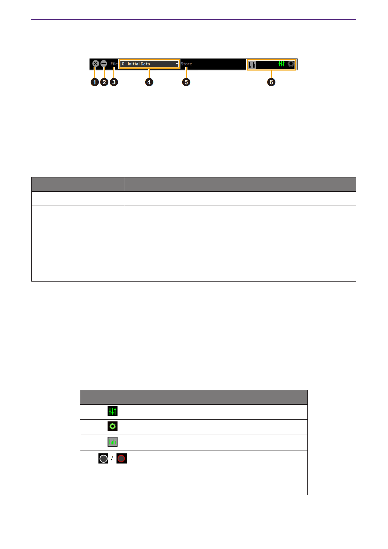
Operating the Tool Area
This is the area for configuring the overall common settings of dspMixFx UR-C.
➊ Quit
Quits dspMixFx UR-C.
➋ Minimize
Minimizes the dspMixFx UR-C window.
➌ File
Displays four different menus.
Menu Descriptions
Open Opens the settings file of dspMixFx UR-C.
Save Saves the settings file of dspMixFx UR-C to a computer.
Import Scene Imports a scene from a dspMixFx UR-C settings file. Select a file in the dialog
box. The [IMPORT SCENE] window is displayed. On the left side of the [IMPORT
SCENE] window, select the dspMixFx UR-C settings file and scene to import. On
the right side of the [IMPORT SCENE] window, select the import destination.
Click [OK] to import the scene.
Initialize All Scenes Initialize all the saved scenes.
➍ Scene
Indicates the scene name. You can change the scene name by clicking on it. Clicking the button on the
right (▼) opens the window for calling up other scenes.Call up the desired scene by clicking it.
➎ Store
Opens the Scene Store window. Enter the desired scene name into the STORE NAME field. Select the
destination for storing the scene in the No. NAME field. Click [OK] to store the scene.
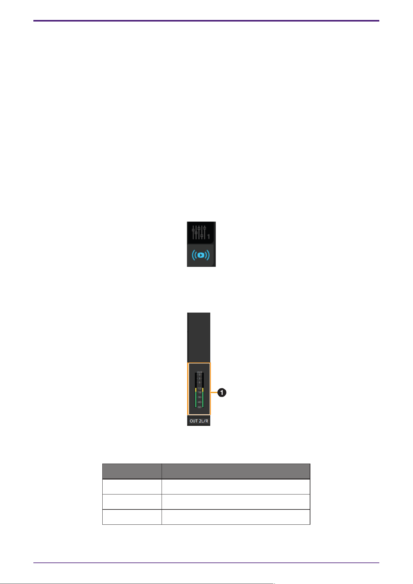
➏ Selecting windows
Selects the desired dspMixFx UR-C window. The selected window icon lights in green.
Menu Description
Main Window
Setup Window
Meter Window
(UR24C only)
Indicates the monitor mode settings.
DAW: white
DJ: red
Clicking this opens the Setup Window.
Startup
4 | dspMixFx User Guide
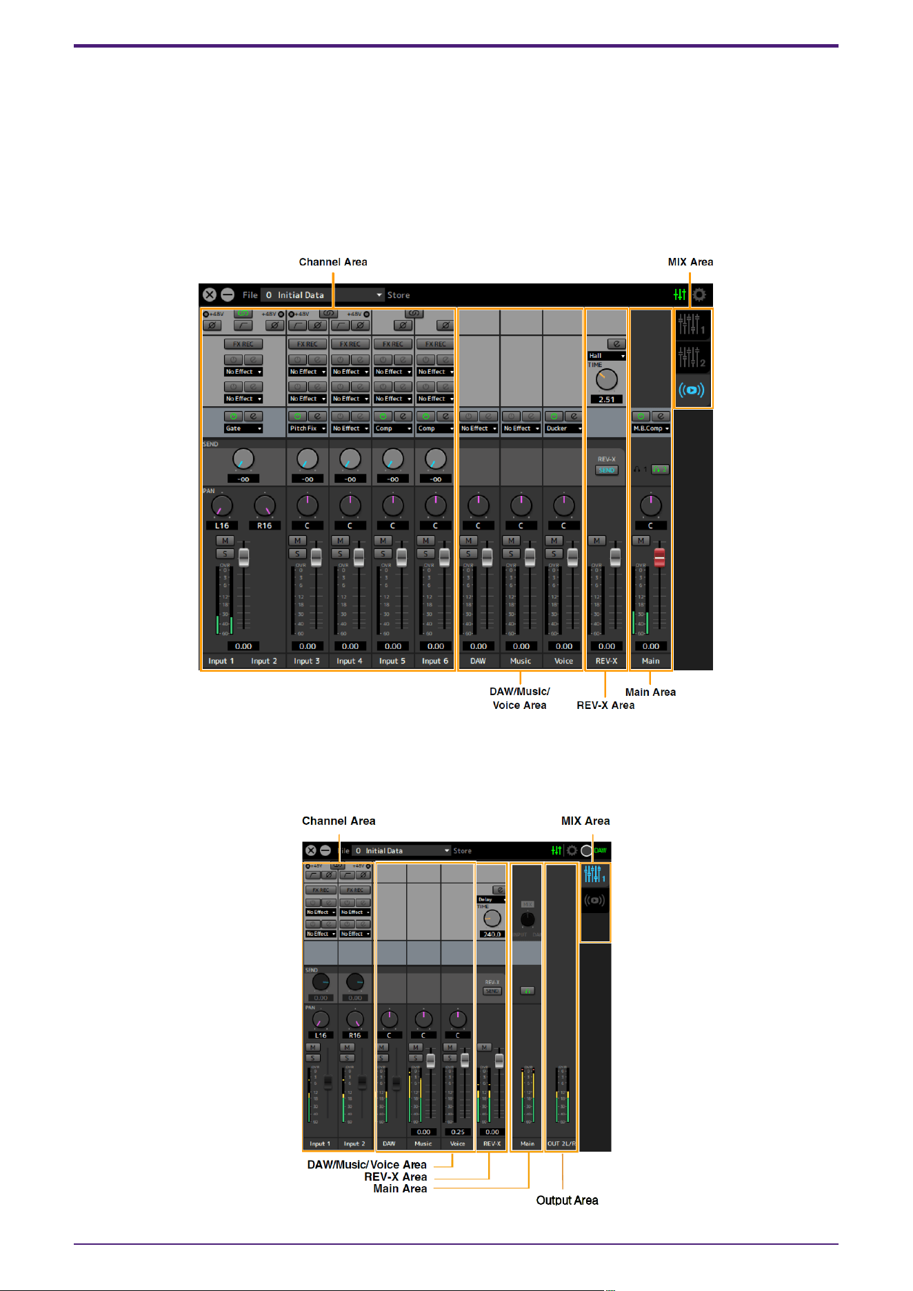
Operating the Main Window
This window is for configuring the entire signal flow. The Main Window consists of five areas.
・Channel Area
・DAW/Music/Voice Area
・REV-X Area
・Main Area
・MIX Area
UR24C only
The Main Window consists of six areas: the five areas mentioned above and an Output Area.
・Output Area (UR24C only)
Startup
dspMixFx User Guide | 5
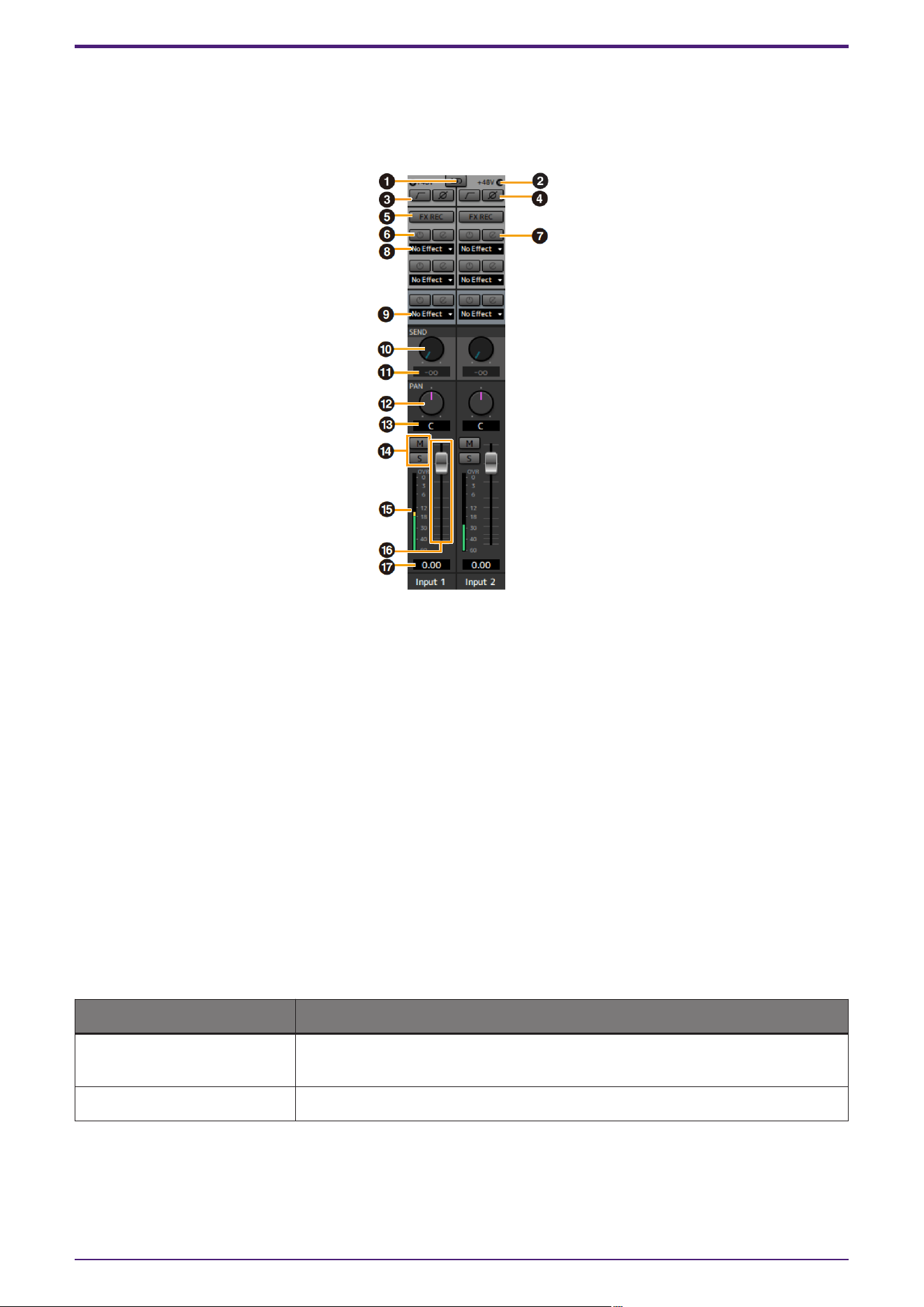
Channel Area
This is the area for configuring the input channel settings.
[Example when Streaming is selected (REV-X Send is turned on)]
➊ Channel Link
Turns on (lit) and off (unlit) the channel link function of two adjacent channels. When this is on, two mono
channels will become one stereo channel.
➋ +48V
Indicates the on (lit) and off (unlit) status of the phantom power function of the device.
➌ High Pass Filter
Turns on (lit) and off (unlit) the high pass filter. To select the cutoff frequency of the high pass filter, use
the “Setup Window.”
UR44C/URX44C: Not available on [LINE INPUT 5/6].
➍ Phase
Turns on (lit) and off (unlit) the phase inversion of the signal.
➎ FX REC
Turn the FX REC (effect recording) on and off.
Settings Description
On (lit) Applies an effect to both the monitor signal (sent to the device) and the
recording signal (sent to the DAW software).
Off (unlit) Applies an effect to only the monitor signal (sent to the device).
➏ Effect On/Off
Turns the Effect on (lit) and off (unlit).
Startup
6 | dspMixFx User Guide
➐ Effect Edit
Opens (lit) and closes (unlit) the selected effect setup window.
➑ Effect Type
Selects the effect type.
Settings: No Effect, Ch.Strip, Clean, Crunch, Lead, Drive, Pitch Fix
NOTE
The maximum number of effects that can be used simultaneously is limited. Refer to “Limitations on the
use of effects” in the User Guide for your UR-C/URX-C series device.
➒ Streaming Effects
Displayed only when Streaming mix has been selected in the MIX area.
SThis effect is applied only to the audio played in the streaming mix. It does not affect the output signal
from each channel to DAW.
No Effect, Gate, or Comp can be selected as the effect type.
➓ REV-X Send
Adjusts the signal level which is sent to REV-X. This setting can only be configured when REV-X Send is
enabled in the REV-X area.
Range: −∞ dB–+6.00 dB
⓫ REV-X Send Value
Displays and adjusts the REV-X send value. Enable editing of the value by double clicking the number.
This setting can only be configured when REV-X Send is enabled (lit) in the REV-X area.
⓬ Pan
Adjusts the Pan.
UR22C/URX22C: Displayed only when Streaming mix has been selected in the MIX area.
Range: L16–C–R16
⓭ Pan Value
Displays and adjusts the Pan value.Enable editing of the value by double clicking the number.
⓮ Mute & Solo
Turns the Mute (M) & Solo (S) on (lit) and off (unlit).
⓯ Level Meter
Indicates the signal level. Peak hold is normally set to on.
Display color Description
Green Up to −18 dB
Yellow Up to 0 dB
Red If Clipped
Startup
dspMixFx User Guide | 7

⓰ Fader
Adjusts the signal level.
On the UR22C, URX22C, and UR24C, this can be used only when Streaming mix has been selected in the
MIX area.
When the normal mix is selected, the level value set by the MIX knob on the front panel is displayed and
this cannot be operated.
Range: −∞ dB–+6.00 dB
⓱ Fader Value
Displays and adjusts the Fader Value.Enable editing of the value by double clicking the number.
Startup
8 | dspMixFx User Guide
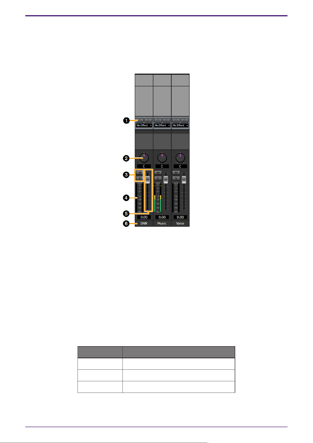
DAW/Music/Voice Area
This is the area for configuring the DAW channel settings.
When connected to a computer, a Music channel and a Voice channel have been added. (The Music channel and
Voice channel are not displayed when connected to iPad or iPhone.)
[Example when Streaming is selected]
➊ Streaming Effects
Displayed only when Streaming mix has been selected in the MIX area.
This effect is applied only to the audio played in the streaming mix.
No Effect and Ducker can be selected as the effect type.
➋ Balance
Adjusts the volume balance of the left and right channels.
Range: L16–C–R16
➌ Mute & Solo
Turns the Mute (M) & Solo (S) on (lit) and off (unlit).
➍ Level Meter
Indicates the signal level. Peak hold is normally set to on.
Display color Description
Green Up to −18 dB
Yellow Up to 0 dB
Red If Clipped
Startup
dspMixFx User Guide | 9

➎ Fader
Adjusts the signal level.
On the UR22C, URX22C, and UR24C DAW channel, this can be used only when Streaming mix has been
selected in the MIX area.
When the normal mix is selected, the level value set by the MIX knob on the front panel is displayed and
this cannot be operated.
Range: −∞ dB–+6.00 dB
➏ Channel Name
You can input text for each channel by double clicking on each channel.
Startup
10 | dspMixFx User Guide
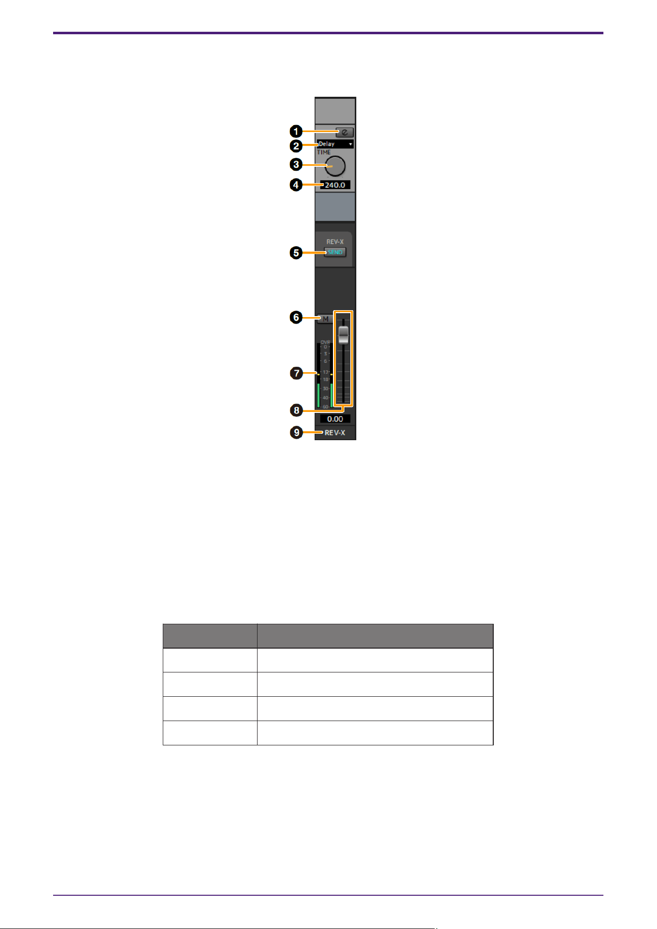
REV-X Area
This is the area for configuring the REV-X channel settings.
➊ REV-X Edit
Opens (lit) and closes (unlit) the “REV-X” setup window.
➋ REV-X Type
Selects the REV-X type.
Settings: Hall, Room, Plate, Delay
➌ REV-X Time
Adjusts the reverb time of REV-X. This parameter links to Room Size. The adjustable range varies
depending on REV-X type.
REV-X Type Range
Hall 0.289 sec–29.0 sec
Room 0.260 sec–26.0 sec
Plate 0.333 sec–33.3 sec
Delay 0.0001 sec–1.3 sec
➍ REV-X Time Value
Displays and adjusts the REV-X Time value. Enable editing of the value by double clicking the number.
➎ REV-X Send
Enables the REV-X send for the MIX you want to operate.
Startup
dspMixFx User Guide | 11
➏ Mute
Indicates the on (lit) and off (unlit) status of the Mute.
➐ Level Meter
Indicates the signal level. Peak hold is normally set to on.
Display color Description
Green Up to −18 dB
Yellow Up to 0 dB
Red If Clipped
➑ REV-X Return Fader
Adjusts the return level of REV-X.
➒ Channel Name
You can input text for each channel by double clicking on each channel.
Startup
12 | dspMixFx User Guide
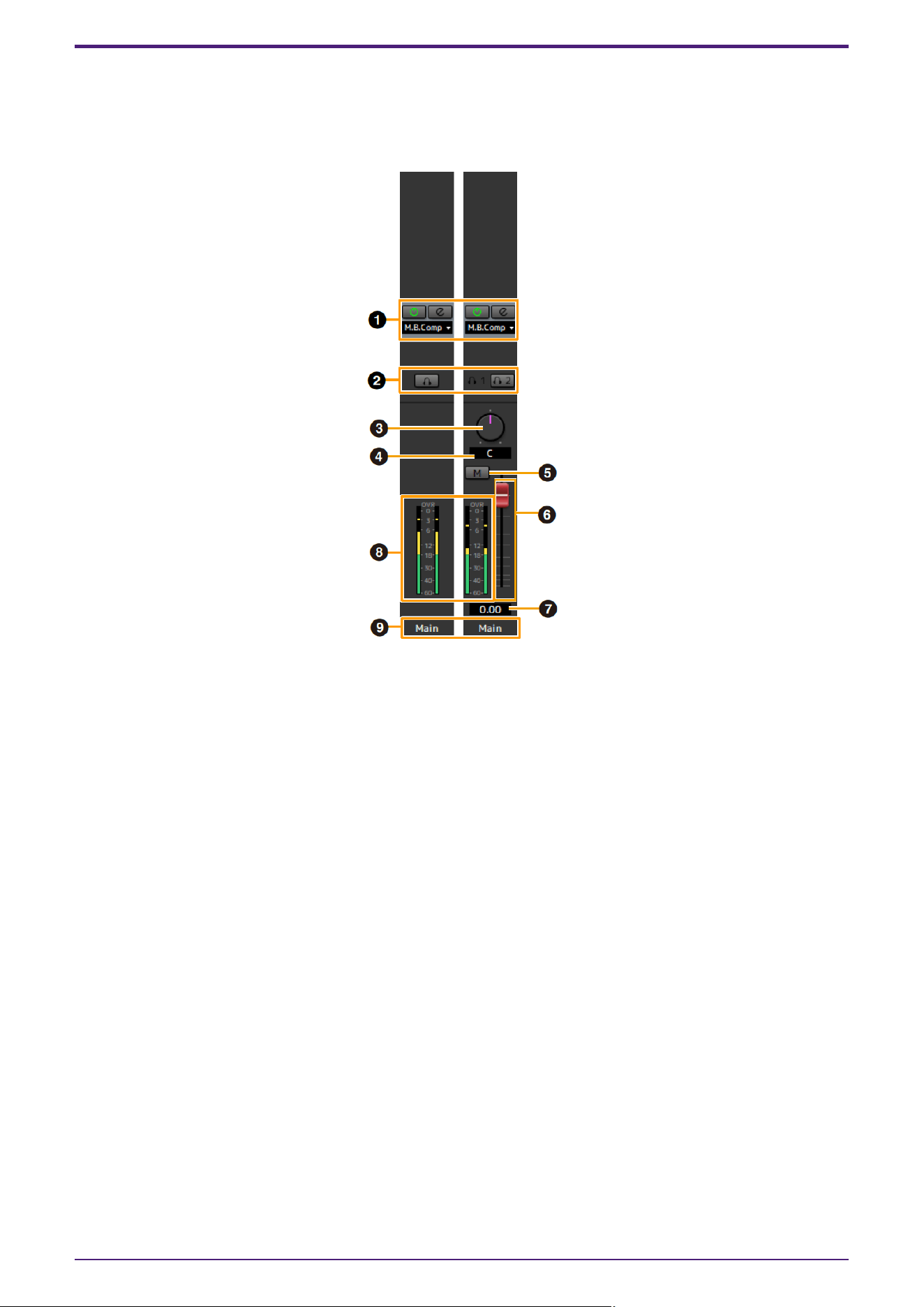
Main Area
This is the area for configuring the main channel settings.
[Example when Streaming is selected]
➊ Streaming Effects
Displayed only when Streaming mix has been selected in the MIX area.
This effect is applied only to final stage of the streaming mix.
No Effect and Multi-Band Compressor (M.B.Comp) can be selected as the effect type.
➋ MONITOR/PHONES
UR22C/URX22C/UR24C: Select the mix that will be output to the MAIN OUTPUT and the PHONES jack.
UR44C/URX44C/UR816C: Turns the two headphones output on (lit) or off (unlit). You can output the MIX
selected in the MIX area to the PHONES by turning this on.
NOTE
UR44C/URX44C: With [PHONES 2], either MIX 1 / MIX 2/Streaming can be selected.[PHONES 1] is fixed to
MIX 1 and cannot be changed.
UR816C: With [PHONES 1] / [PHONES 2], MIX 1, MIX 2, MIX 3, MIX 4, or Streaming can be selected.
➌ Balance
Adjusts the volume balance of the left and right channels.
Range: L16–C–R16
➍ Balance Value
Displays and adjusts the Balance value. Enable editing of the value by double clicking the number.
➎ Mute
Turn the mute function on (lit) and off (unlit).
Startup
dspMixFx User Guide | 13
➏ Master Fader
Adjusts the signal level.
Range: −∞ dB–+6.00 dB
➐ Master Fader Value
Displays and adjusts the Master Fader value. Enable editing of the value by double clicking the number.
➑ Level Meter
Indicates the signal level.
➒ Channel Name
You can input text for each channel by double clicking on each channel.
MIX Area
This is the area for selecting the MIX you want to configure.
You can copy the Main Window settings of the MIX by dragging and dropping.
On the UR816C, when Streaming is selected in GENERAL SETTINGS > Mix4 on the setup screen, Mix4 switches
to Streaming.
Output Area (UR24C only)
This section indicates the output signal level of the Output area.
➊ Level Meter
Indicates the signal level. Peak hold is normally set to on.
Display color Description
Green Up to −18 dB
Yellow Up to 0 dB
Red If Clipped
Startup
14 | dspMixFx User Guide
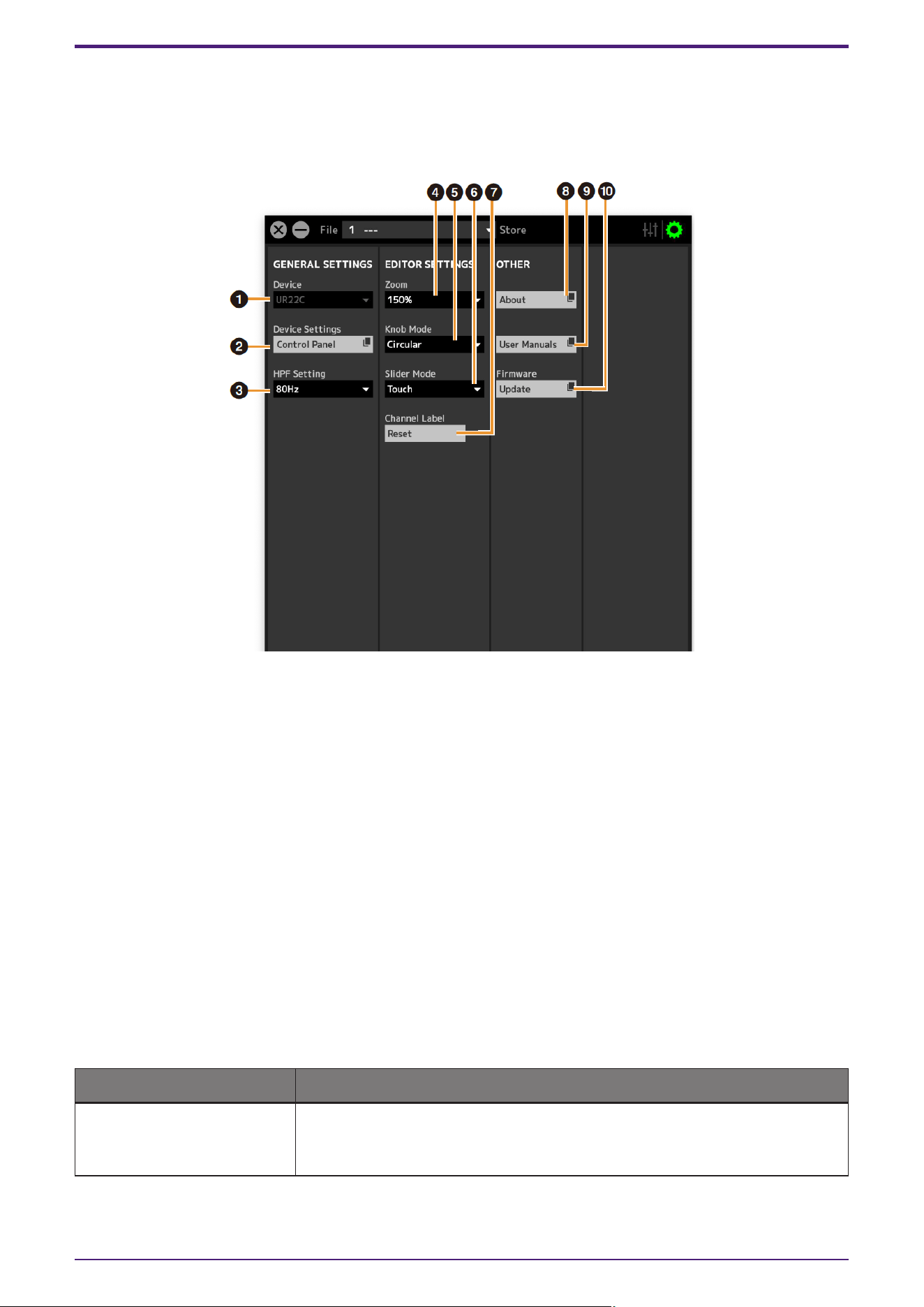
Operating the Setup Window
This window is for configuring the common settings of the device.
When Connected to a Computer
➊ Device
If multiple dspMixFx devices are connected, select the device you want to operate.
➋ Device Settings
Opens the Control Panel.
➌ HPF Setting
Selects the cutoff frequency of the high pass filter.
UR44C/URX44C: Not available on [LINE INPUT 5/6].
Options: 120 Hz, 100 Hz, 80 Hz, 60 Hz, 40 Hz
➍ Zoom
Changes the window size.
Options: 100%, 150%, 200%, 250%, 300%
➎ Knob Mode
Selects the method of operating the knobs on dspMixFx UR-C.
Settings Description
Circular Drag in a circular motion to increase and decrease the parameter. Drag on a
dial clockwise to increase, and counterclockwise to decrease. If you click any
point on the knob, the parameter will jump there instantly.
Startup
dspMixFx User Guide | 15
Settings Description
Linear Drag in a linear motion to increase and decrease the parameter. Drag upward
or rightward to increase, and downward or leftward to decrease. Even if you
click any point on the knob, the parameter will not jump there.
➏ Slider Mode
Selects the method of operating the sliders and faders on dspMixFx UR-C.
Settings Description
Jump Click any point on the slider and fader to increase and decrease the parameter.
If you click any point on the slider and fader, the parameter will jump there
instantly.
Touch Drag the handle of the slider and fader to increase and decrease the parameter.
Even if you click any point on the slider and fader, the parameter will not jump
there.
➐ Channel Label Reset
Resets all edited channel names at once.
➑ About
Indicates the version of the firmware and software.
➒ User Manuals
Clicks to open the “dspMixFx User Guide” (this guide) in your browser.
➓ Firmware
Updates the firmware of the device.
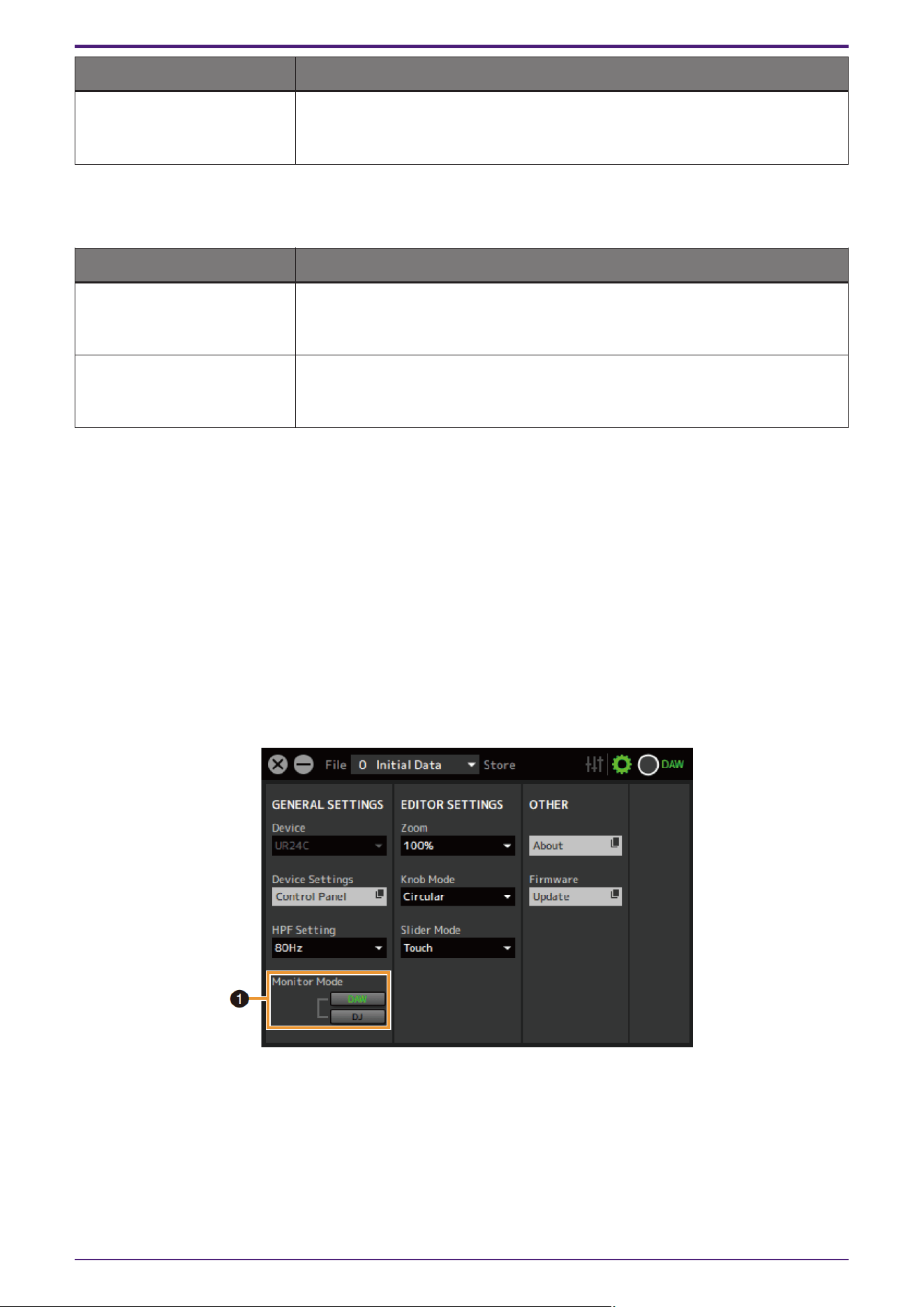
UR24C only
➊ Monitor Mode
Switches the mode settings.
Options: DAW, DJ
Startup
16 | dspMixFx User Guide
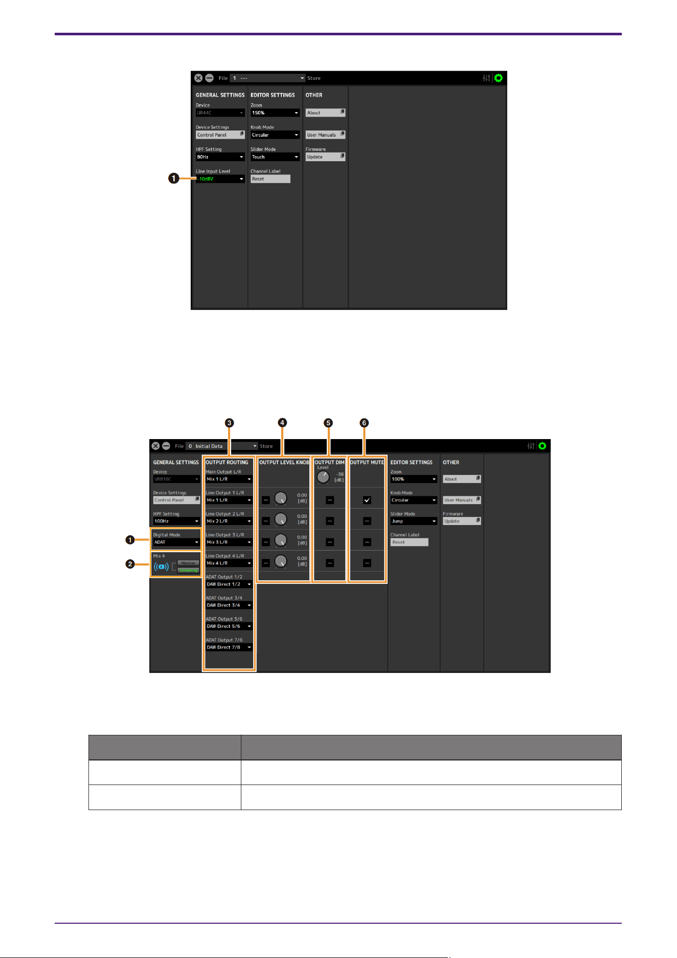
UR44C/URX44C only
➊ Line Input Level
Selects the input signal level of [LINE INPUT 5/6].
Options: +4 dBu, −10 dBV
UR816C only
➊ Digital Mode
Selects the input and output signal format of the [OPTICAL IN] and [OPTICAL OUT] jacks.
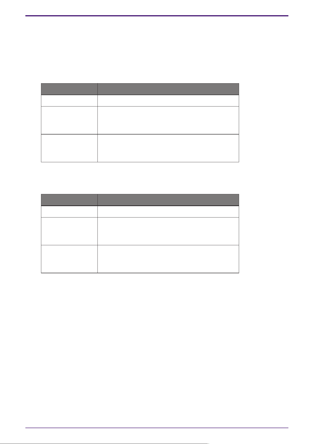
Option Description
ADAT Input and output signals of up to 8 channels.
S/PDIF Input and output of 2-channel (stereo) signals.
When ADAT is selected, the input and output signals of up to eight channels at 44.1 kHz and 48 kHz, or up
to four channels at 88.2 kHz and 96 kHz, or up to two channels at 176.4 kHz and 192 kHz.
When S/PDIF is selected, the input and output signals of up to two channels at any available sample rate.
Startup
dspMixFx User Guide | 17
➋ Mix4
Selects whether to use Mix4 as either a streaming mix or as a monitor mix.
➌ OUTPUT ROUTING
Selects the MIX of the output jacks on the device. The number of OUT options displayed here varies
depending on the sample rate or DIGITAL MODE setting.
ADAT
Output jack Options
Main Output L/R MIX1 to MIX4
Line Output 1 L/R to 4
L/R
MIX1 to MIX4
DAW Direct 1/2 to 7/8*
ADAT 1/2 to 7/8*
ADAT Output 1/2 to
7/8*
MIX1 to MIX4
DAW Direct 1/2 to 7/8
Input 1/2 to 7/8
*The number of channels differs depending on the sample rate.
S/PDIF
Output jack Options
Main Output L/R MIX1 to MIX4
Line Output 1/2 to 7/8
MIX1 to MIX4
DAW Direct 1/2 to 7/8*
S/PDIF In L/R
S/PDIF Output L/R
MIX1 to MIX4
DAW Direct 1/2 to 7/8
Input 1/2 to 7/8
*The number of channels differs depending on the sample rate.
➍ OUTPUT LEVEL KNOB
Determines the [LINE OUTPUT] jack which is to be affected by the [OUTPUT] knob on the front panel.
➎ OUTPUT DIM
Determines the [LINE OUTPUT] jack which is to be affected by the [DIM] switch on the front panel. Also,
this adjusts the attenuation level when the [DIM] switch is on.
➏ OUTPUT MUTE
Determines the [LINE OUTPUT] jack which is to be affected by the [MUTE] switch on the front panel.
Startup
18 | dspMixFx User Guide
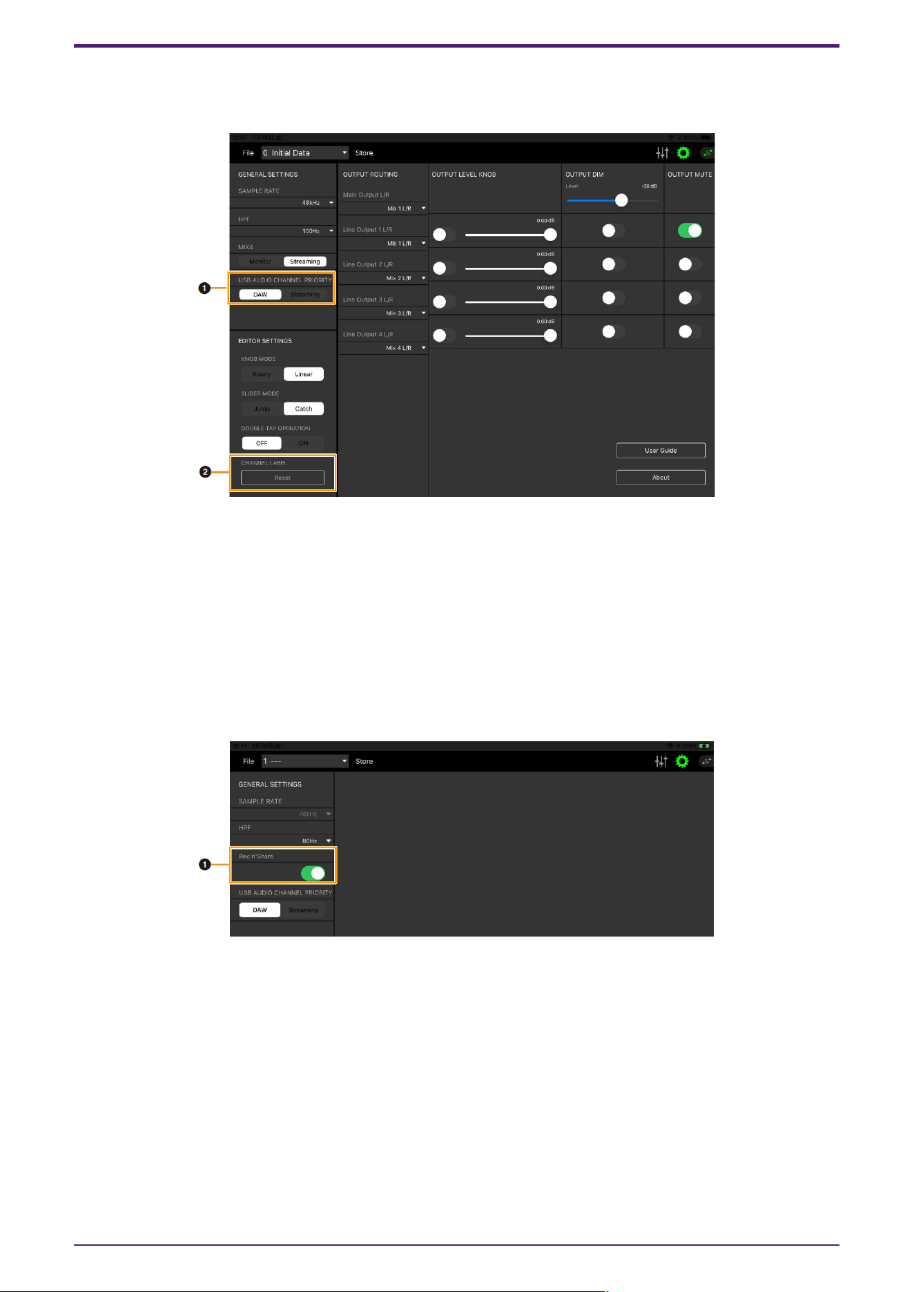
When Connected to an iPad/iPhone
This section describes how to operate the dspMixFx app for iPad/iPhone.
➊ USB AUDIO CHANNEL PRIORITY
Selects the order of the channels to be output from the UR-C to the iPad/iPhone. If DAW is selected, the
signals will be arranged in the order of signals output directly to the DAW from the input channels and the
output from the streaming mix will be added to the end. If Streaming is selected, the output from the
streaming mix is arranged first. When used for streaming, it is recommended that you select “Streaming.”
➋ CHANNEL LABEL
Resets all edited channel names at once.
UR22C/URX22C only
➊ Rec’n’Share
Please turn this parameter on when using the Rec’n’Share application. There are 2IN/2OUT send & receive
channels for the iPad/iPhone and USB audio, which allows audio to be sent to and received from the
Rec’n’Share application.
Startup
dspMixFx User Guide | 19
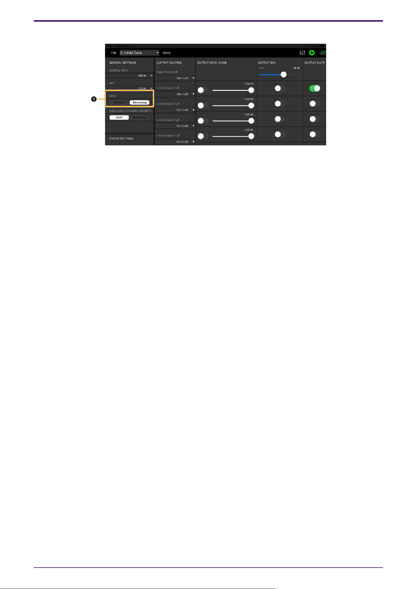
UR816C only
➊ Mix4
Selects whether to use Mix4 as either a streaming mix (Streaming) or as a monitor mix (Monitor).
Startup
20 | dspMixFx User Guide

Effect
There are two categories of dspMixFx effects, based on their intended use.
1. Standard Effect
These effects are suitable for general purposes such as music production and instrument performance. They are
categorized as follows in each area of the Main Window.
Channel Effect
・Sweet Spot Morphing Channel Strip
・Guitar Amp Classics (Clean, Crunch, Lead, Drive)
・PITCH FIX
REV-X Area Effect
・REV-X (Hall, Room, Plate)
・Delay
2. Streaming Effect
These effects are applied to the streaming mix. They are categorized as follows in each area of the Main
Window.
Channel Effect
・GATE
・COMPRESSOR
DAW/Music/Voice Effect
・DUCKER
Main Area Effect
・MULTI-BAND COMPRESSOR
Effect
dspMixFx User Guide | 21
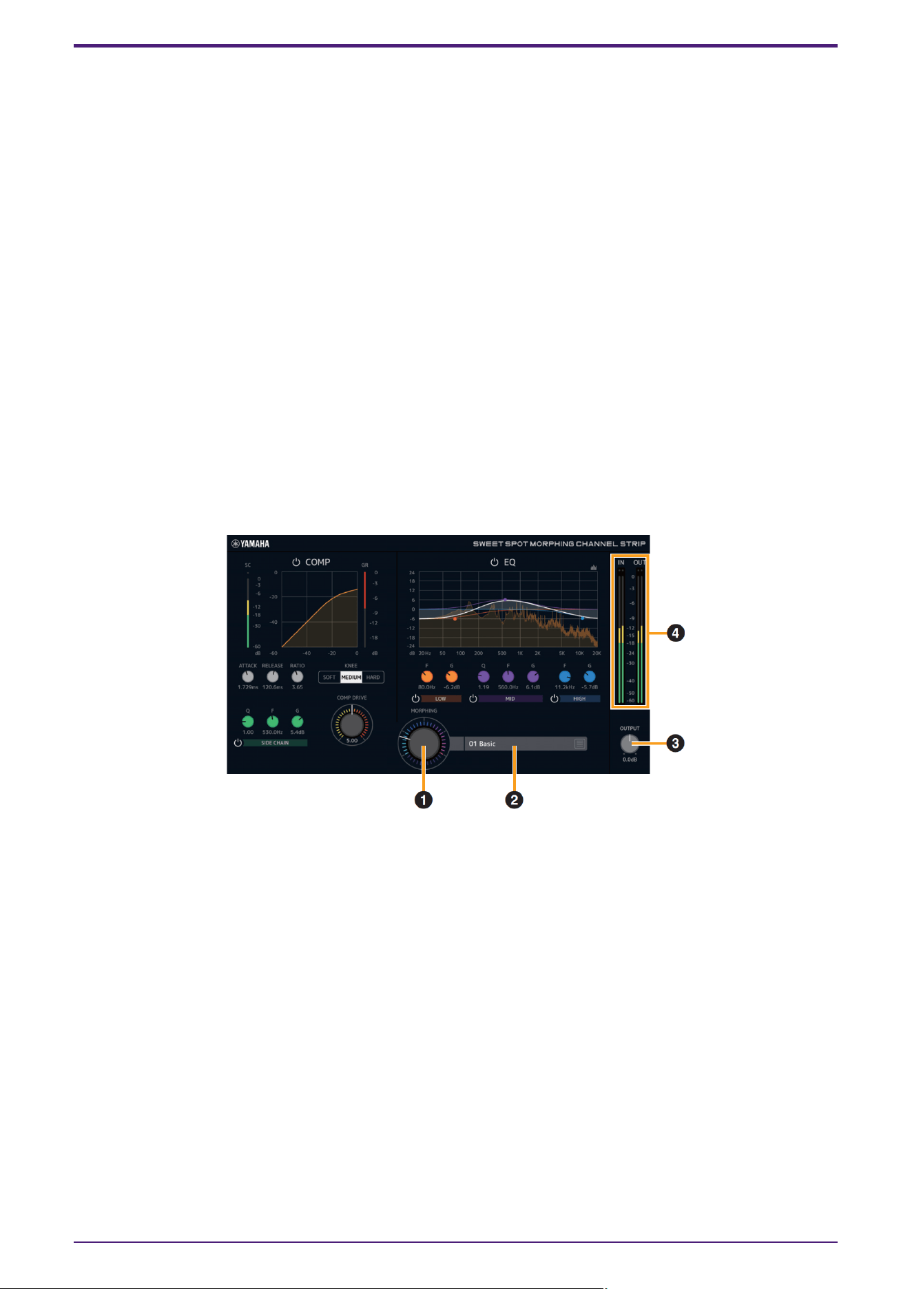
Sweet Spot Morphing Channel Strip
The Sweet Spot Morphing Channel Strip (“Channel Strip” for short) is a multi-effect that combines compression
and EQ. Advanced sound engineering know-how is condensed into a number of convenient presets that can be
simply and instantly recalled, for professional results.
Six channel strips are provided, and each can be assigned to the monitor sound only, or to both the monitor and
recorded sound.
The Channel Strip equipped with the device and the Channel Strip of the VST Plug-in version have the same
parameters. When using the Channel Strip on Cubase series programs, you can share the settings between the
built-in Channel Strip and the Channel Strip of the VST Plug-in version as a preset file.
Also, when assigning the Channel Strip of the VST Plug-in version to the effect slot on Cubase series programs,
select it from the [Dynamics] category (in the case of the default settings).
For more information about the VST Plug-in version, refer to the “Basic FX Suite Operation Manual.”
How to Open the Window
・From dspMixFx UR-C
Select the “Channel Strip” from the “Effect Type”, then click “Channel Strip Edit” in the section “Channel Area.”
・From Dedicated Windows for Cubase Series
Select the “Channel Strip” from the “Effect Type”, then click “Channel Strip Edit” in the section “Input Settings
Window.”
[Common to Compressor and Equalizer]
➊ MORPHING
Adjusts the parameter of the Sweet Spot Data.
You can simultaneously adjust the compressor and equalizer settings which are set to five points around
this knob by turning this knob. When you set the knob between two adjacent points, the compressor and
equalizer settings will be set to an intermediate value.
➋ Sweet Spot Data
Selects the Sweet Spot Data.
➌ OUTPUT
Adjusts the total gain of the Channel Strip.
Range: −18.0 dB–+18.0 dB
➍ Level Meters
Indicates the input and output levels of the Channel Strip.
Effect
22 | dspMixFx User Guide
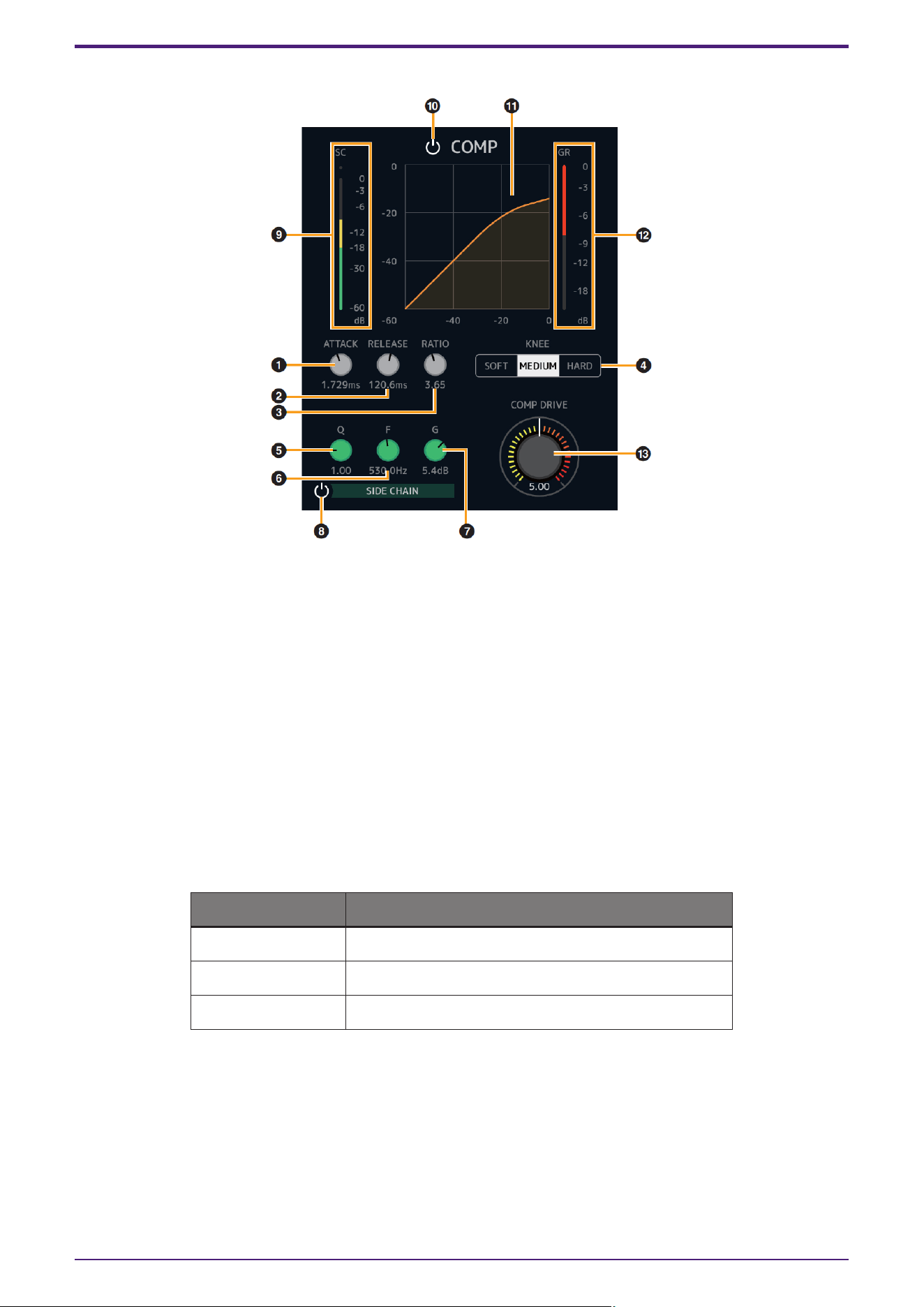
[Compressor]
➊ ATTACK
Adjusts the attack time of the compressor.
Range: 0.092 msec–80.00 msec
➋ RELEASE
Adjusts the release time of the compressor.
Range: 9.3 msec–999.0 msec
➌ RATIO
Adjusts the ratio of the compressor.
Range: 1.00–∞
➍ KNEE
Selects the knee type of the compressor.
Options Description
SOFT Produces the most gradual change.
MEDIUM Results in a setting midway between SOFT and HARD.
HARD Produces the sharpest change.
➎ SIDE CHAIN Q
Adjusts the band width of the side chain filter.
Range: 0.50–16.00
➏ SIDE CHAIN F
Adjusts the center frequency of the side chain filter.
Range: 20.0 Hz–20.0 kHz
Effect
dspMixFx User Guide | 23
➐ SIDE CHAIN G
Adjusts the gain of the side chain filter.
Range: −18.0 dB–+18.0 dB
➑ SIDE CHAIN On/Off
Turns the side chain on (lit) and off (unlit).
➒ SC Meter
Indicates the trigger signal level for the side chain.
➓ COMPRESSOR On/Off
Turns the compressor on (lit) and off (unlit).
⓫ Compressor Curve
This graph indicates the approximate compressor response. The vertical axis indicates the output signal
level, and the horizontal axis indicates the input signal level.
⓬ Gain Reduction Meter
Indicates the gain reduction.
⓭ COMP DRIVE
Adjusts the degree to which the compressor is applied. The higher the value, the greater the effect.
Range: 0.00–10.00
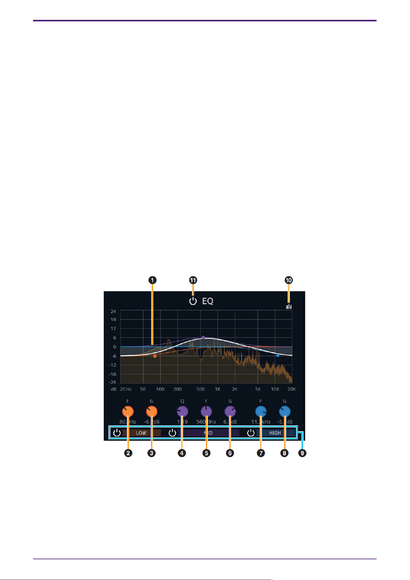
[Equalizer]
➊ Equalizer Curve
This graph indicates the characteristics of the 3-band equalizer.
The vertical axis indicates the gain, and the horizontal axis indicates the frequency. You can adjust LOW,
MID, and HIGH by dragging each handle in the graph.
➋ LOW F
Adjusts the center frequency of the low band.
Range: 20.0 Hz–1.00 kHz
Effect
24 | dspMixFx User Guide

➌ LOW G
Adjusts the gain of the low band.
Range: −18.0 dB–+18.0 dB
➍ MID Q
Adjusts the band width of the middle band.
Range: 0.50–16.00
➎ MID F
Adjusts the center frequency of the middle band.
Range: 20.0 Hz–20.0 kHz
➏ MID G
Adjusts the gain of the middle band.
Range: −18.0 dB–+18.0 dB
➐ HIGH F
Adjusts the center frequency of the high band.
Range: 500.0 Hz–20.0 kHz
➑ HIGH G
Adjusts the gain of the high band.
Range: −18.0 dB–+18.0 dB
➒ EQ Band On/Off
Turns each EQ band on (lit) and off (unlit) individually.
➓ Spectrum Display On/Off
Turns the Spectrum Display of the Equalizer Curve on (lit) and off (unlit).
⓫ EQ On/Off
Turns the equalizer on (lit) and off (unlit).
Effect
dspMixFx User Guide | 25
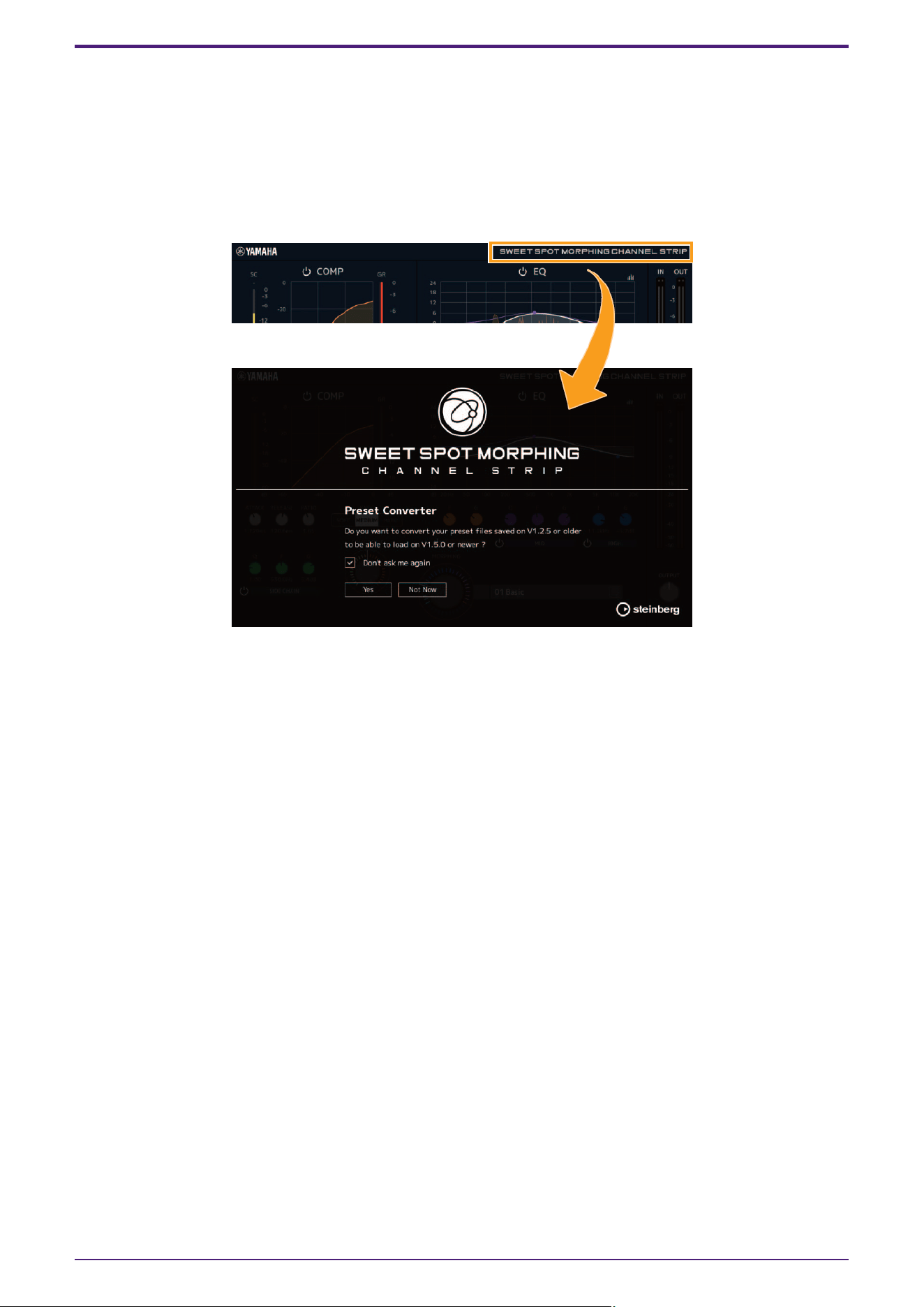
If you are using Sweet Spot Morphing Channel Strip V1.2.5 or earlier
Added the Preset Converter window to convert Presets made by Sweet Spot Morphing Channel Strip V1.2.5 or
earlier to be compatible with V1.5.0 or later.
The Preset Converter window automatically appears when opening the Sweet Spot Morphing Channel Strip. If
you want to prevent it from appearing, check “Don’t ask me again” and will not open the next time.
If the Preset Converter does not appear automatically or if you want to display it manually, click the logo in the
upper right corner of the Sweet Spot Morphing Channel Strip window.
Click the “Yes” button to enable use of Presets saved in previous versions.
Click the “Not Now” button to open the plug-in without converting the previous Presets.
NOTICE
* Presets created by V1.5.0 or later are not compatible with V1.2.5 or earlier.
* When V1.5.0 or later has been installed to the computer that was using V1.2.5 or earlier, the Mono version of
the V1.2.5 or earlier will remain. If you open a project file with V1.2.5 or earlier in this state, the plug-in V1.2.5 or
earlier will be loaded to the channel to which the Mono version has been assigned. If you want to replace it to
one of V1.5.0 or later, re-select the appropriate channel plug-ins to V1.5.0 or later.
Effect
26 | dspMixFx User Guide
Guitar Amp Classics
Guitar Amp Classics are guitar amp simulations that make extensive use of advanced Yamaha modeling
technology.
Four amp types with different sonic characteristics are provided.
The Guitar Amp Classics equipped with the device and the Guitar Amp Classics of the VST Plug-in version have
the same parameters. When using the Guitar Amp Classics on Cubase series programs, you can share the
settings between the built-in Guitar Amp Classics and the Guitar Amp Classics of the VST Plug-in version as a
preset file. Also, when assigning the Guitar Amp Classics of the VST Plug-in version to the effect slot on Cubase
series programs, select it from the [Distortion] category (in the case of the default settings). Note that Guitar
Amp Classics equipped with the device cannot be used when the sample rate is set to 176.4 kHz or 192 kHz.
For more information about the VST Plug-in version, refer to the “Basic FX Suite Operation Manual.”
How to Open the Window
・From dspMixFx UR-C
Select the “Guitar Amp Classics” from the “Effect Type”, then click “Effect Edit” in the section “Channel Area.”
・From Dedicated Windows for Cubase Series
Select the “Guitar Amp Classics” from the “Effect Type”, then click “Effect Edit” in the section “Input Settings
Window.”
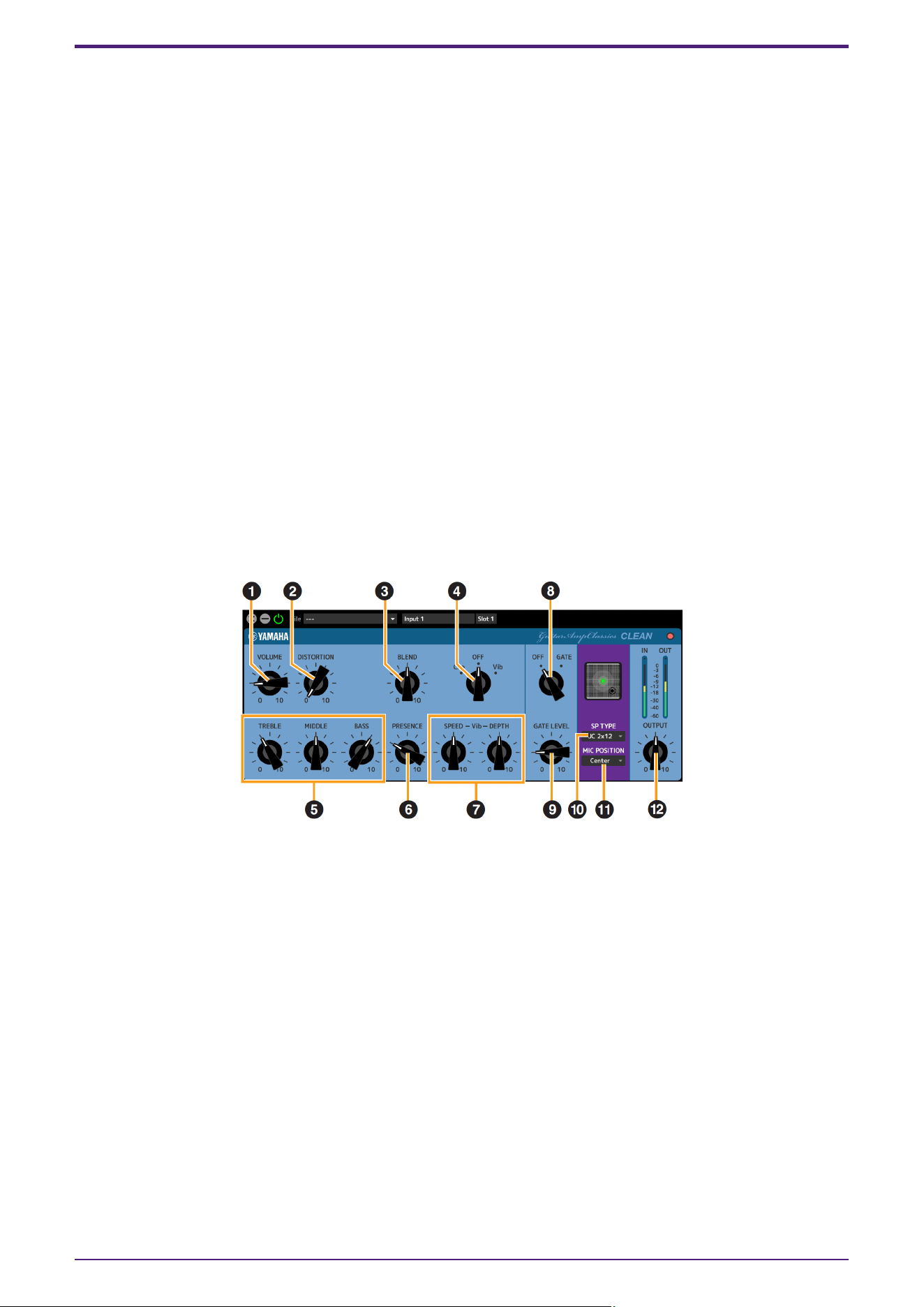
CLEAN
This amp type is optimized for clean tones, effectively simulating the tight brilliance of transistor amplifiers. The
tonal character of this amp model provides an ideal platform for recording with multi-effects. It also features
built-in chorus and vibrato effects.
➊ VOLUME
Adjusts the amplifier’s input level.
➋ DISTORTION
Adjusts the depth of distortion produced.
➌ BLEND
Adjusts the balance between the direct and effect sound.
➍ Cho/OFF/Vib
Turns the Chorus or Vibrato effect on or off. Set to [Cho] to turn the Chorus effect on, or to [Vib] to turn the
Vibrato effect on.
➎ TREBLE/MIDDLE/BASS
These three controls adjusts the amplifier’s tonal response in the high, middle, and low frequency ranges.
➏ PRESENCE
Can be adjusted to emphasize the high frequencies and overtones.
Effect
dspMixFx User Guide | 27
➐ SPEED/DEPTH
These controls adjust the speed and depth of the Vibrato effect when it is on.
The SPEED and DEPTH controls only work with the Vibrato effect, and are disengaged when the
Cho/OFF/Vib control, above, is set to “Cho” or “OFF.”
➑ OFF/GATE
Turns the noise gate on and off.
➒ GATE LEVEL
Adjusts the gate level.
➓ SP TYPE
Selects the type of cabinet.
For more information about the characteristics of each type, refer to the Guitar Amp Classics Reference
section “Cabinet types and characteristics.”
Type and configuration: BS 4×12", AC 2×12", AC 1×12", AC 4×10", BC 2×12", AM 4×12", YC 4×12", JC 2×12"
⓫ MIC POSITION
Selects the position of the virtual microphone for placement in front of the cabinet. You can also select
the microphone position by clicking on the speaker image.
Position Description
Center Microphone placement aiming at the center of the speaker cone.
Edge Microphone placement aiming at the edge of the speaker cone.
⓬ OUTPUT
Adjusts the final output level.
Effect
28 | dspMixFx User Guide
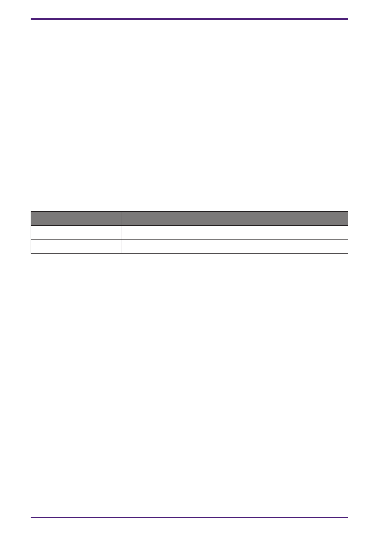
CRUNCH
This is the amp type to use when you want lightly overdriven crunch tones. The CRUNCH model simulates the
type of vintage tube amplifiers that are favored for blues, rock, soul, R&B, and similar styles.
➊ Normal/Bright
Selects a normal or bright tonal character. The [Bright] setting emphasizes the high-frequency overtones.
➋ GAIN
Adjusts the input level applied to the preamp stage. Rotate clockwise to increase the amount of overdrive
produced.
➌ TREBLE/MIDDLE/BASS
These three controls adjust the amplifier’s tonal response in the high, middle, and low frequency ranges.
➍ PRESENCE
Can be adjusted to emphasize the high frequencies and overtones.
➎ OFF/GATE
Turns the noise gate on and off.
➏ GATE LEVEL
Adjusts the gate level.
➐ SP TYPE
Selects the type of cabinet.
For more information about the characteristics of each type, refer to the Guitar Amp Classics Reference
section “Cabinet types and characteristics.”
Type and configuration: BS 4×12", AC 2×12", AC 1×12", AC 4×10", BC 2×12", AM 4×12", YC 4×12", JC 2×12"
➑ MIC POSITION
Selects the position of the virtual microphone for placement in front of the cabinet. You can also select
the microphone position by clicking on the speaker image.
Position Description
Center Microphone placement aiming at the center of the speaker cone.
Edge Microphone placement aiming at the edge of the speaker cone.
➒ OUTPUT
Adjusts the final output level.
Effect
dspMixFx User Guide | 29
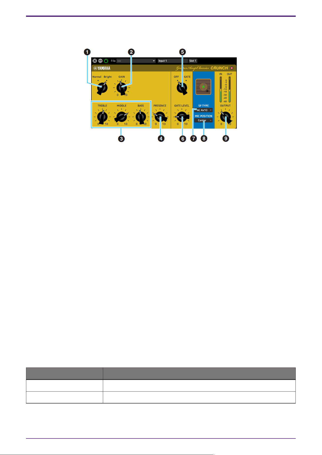
DRIVE
The DRIVE amp type provides a selection of distortion sounds that simulate the tonal character of various
highgain tube amplifiers. From mildly overdriven crunch to heavy distortion suitable for hard rock, heavy metal, or
hardcore styles, this model offers a wide range of sonic capabilities.
➊ AMP TYPE
Six amplifier types are provided.
Types 1 and 2 feature relatively mild distortion that allows picking nuances to come through naturally.
Types 3 and 4 have more pronounced overtones, resulting in a fat, soft tone. Types 5 and 6 deliver wilder,
aggressive distortion with a tight attack.
The even-numbered amp types have greater presence and range than the odd-numbered types.
➋ GAIN
Adjusts the input level applied to the preamp stage. Rotate clockwise to increase the amount of distortion
produced.
➌ MASTER
Adjusts the output level from the preamp stage.
➍ TREBLE/MIDDLE/BASS
These three controls adjust the amplifier’s tonal response in the high, middle, and low frequency ranges.
➎ PRESENCE
Can be adjusted to emphasize the high frequencies and overtones.
➏ OFF/GATE
Turns the noise gate on and off.
➐ GATE LEVEL
Adjusts the gate level.
➑ SP TYPE
Selects the type of cabinet.
For more information about the characteristics of each type, refer to the Guitar Amp Classics Reference
section “Cabinet types and characteristics.”
Type and configuration: BS 4×12", AC 2×12", AC 1×12", AC 4×10", BC 2×12", AM 4×12", YC 4×12", JC 2×12"
Effect
30 | dspMixFx User Guide

➒ MIC POSITION
Selects the position of the virtual microphone for placement in front of the cabinet. You can also select
the microphone position by clicking on the speaker image.
Position Description
Center Microphone placement aiming at the center of the speaker cone.
Edge Microphone placement aiming at the edge of the speaker cone.
➓ OUTPUT
Adjusts the final output level.
Effect
dspMixFx User Guide | 31
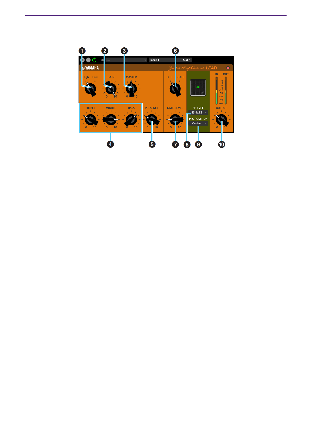
LEAD
The LEAD amp type simulates a high-gain tube amp that is rich in overtones. It is ideally suited to playing lead
guitar lines that will project well in an ensemble, but it can also be set up for crisp accompaniment tones as well.
➊ High/Low
Selects the amp output type. The [High] setting simulates a high-output amp, and allows the creation of
more distorted tones.
➋ GAIN
Adjusts the input level applied to the preamp stage. Rotate clockwise to increase the amount of distortion
produced.
➌ MASTER
Adjusts the output level from the preamp stage.
➍ TREBLE/MIDDLE/BASS
These three controls adjust the amplifier’s tonal response in the high, middle, and low frequency ranges.
➎ PRESENCE
Used to emphasize the high frequencies and overtones.
➏ OFF/GATE
Turns the noise gate on and off.
➐ GATE LEVEL
Adjusts the gate level.
➑ SP TYPE
Selects the type of cabinet.
For more information about the characteristics of each type, refer to the Guitar Amp Classics Reference
section “Cabinet types and characteristics.”
Type and configuration: BS 4×12", AC 2×12", AC 1×12", AC 4×10", BC 2×12", AM 4×12", YC 4×12", JC 2×12"
Effect
32 | dspMixFx User Guide
➒ MIC POSITION
Selects the position of the virtual microphone for placement in front of the cabinet. You can also select
the microphone position by clicking on the speaker image.
Position Description
Center Microphone placement aiming at the center of the speaker cone.
Edge Microphone placement aiming at the edge of the speaker cone.
➓ OUTPUT
Adjusts the final output level.
Guitar Amp Classics Reference
Using the GAIN, MASTER, and OUTPUT Controls
The tonal character of the DRIVE and LEAD amp types can be adjusted over a wide range via the GAIN, MASTER,
and OUTPUT controls.
GAIN adjusts the level of the signal applied to the preamp stage, affecting the amount of distortion produced.
MASTER adjusts the output level from the preamp stage that is then fed to power amp stage. The GAIN and
MASTER control settings have a large effect on the final sound, and the MASTER control may need to be turned
up fairly high in order to drive the power stage sufficiently for optimum tone.The OUTPUT control adjusts the
final output level from the amp model without affecting the distortion or tone, and is useful for adjusting the
guitar’s volume without changing any other aspects of the sound.
Cabinet types and characteristics
The following table shows the cabinet characteristics that are common to each of the four types: CLEAN,
CRUNCH, DRIVE, and LEAD.
SP TYPE Characteristics Speaker
configuration
BS 4×12 British flat stack type with rich cabinet resonance. 4×12"
AC 2×12 American combo type cabinet, featuring a clear tone for versatile
use in various music genres.
2×12"
AC 1×12 American combo type cabinet, featuring a clear tone for ensemble
use.
1×12"
AC 4×10 American combo type cabinet, featuring a bright tone reminiscent
of more traditional guitar sounds.
4×10"
BC 2×12 British combo type cabinet, ideal for distortion sounds and
featuring a wide range with broad treble response.
2×12"
AM 4×12 American stack type cabinet, ideal for matching with high-power
amplifiers and featuring a clear sound contour.
4×12"
YC 4×12 Yamaha F series combo type cabinet, featuring a rich midrange
and a mild high range.
4×12"
JC 2×12 Japanese combo type cabinet, ideal for clean sounds, and
featuring a rich mid-high range plus modulation effects.
2×12"
Effect
dspMixFx User Guide | 33
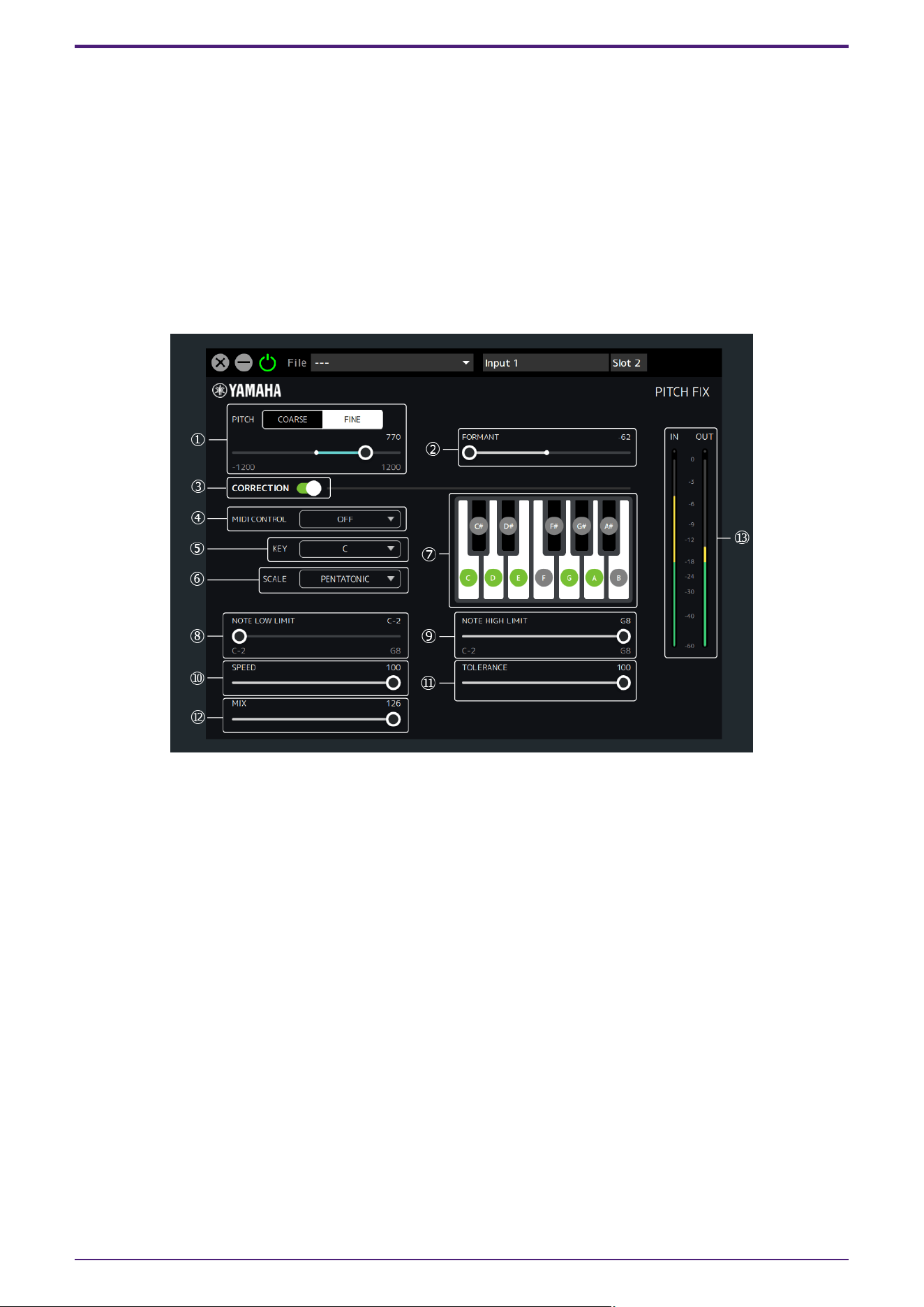
PITCH FIX
Adjusts the pitch and formant, and processes the microphone sound. It can also correct to a specified pitch.
This unit has one Pitch Fix available. Sampling frequencies of 44.1 kHz or 48 kHz can be used. This cannot be
used for channels with Channel Link turned on.
How to Open the Screen
・From dspMixFx UR-C
In the MIX area, after selecting Pitch Fix from “Effect Type” in the channel area, click “Edit effect.”
・From Dedicated Windows for Cubase Series
Select Pitch Fix from “Effect Type” in the effect setting area.Click “Edit effect” to start dspMixFx UR-C, and the
dspMixFx UR-C PITCH FIX screen will open.
➊ PITCH
Adjusts the pitch within a range of one octave up or down. Select the pitch adjustment unit from COARSE
(semitones) or FINE (cents).
When COARSE is selected: −12–+12 (semitones)
When FINE is selected: −1200–+1200 (cents)
➋ FORMANT
Adjusts the formants.
A low value gives a deeper voice quality, and a high value gives a higher voice quality.
Range: −62–+62
➌ CORRECTION
Turns the function to correct to the specified scale ON/OFF. When CORRECTION is OFF, parameters ➍
and after are unavailable.
➍ MIDI CONTROL
Uses MIDI note messages to set the scale correction. It supports both the MIDI IN connector on the main
unit and USB MIDI.
Effect
34 | dspMixFx User Guide
Setting Description
OFF The MIDI setting function is disabled.
SETTING
In this setting, ➏ SCALE can be set to CUSTOM or anything other than
CHROMATIC. If CHROMATIC is selected as SCALE already, it will be changed to
CUSTOM.
・When SCALE is set to CUSTOM:
The scale is specified instead of using the ➐ Keyboard buttons. When a Note
On message of the same scale as the specified scale is received, the specified
scale will be cancelled. Also, this sets ➑ NOTE LOW LIMIT / ➒ NOTE HIGH
LIMIT to the range of the entered scale. Note Off is not supported.
・When SCALE is not set to CUSTOM:
The key of the last note entered is set to the ➎ KEY.
REAL TIME
Specifies the scale correction in real time using Note On/Off. In this setting, ➏
SCALE can be set to CUSTOM or SINGLE. If something other than SINGLE is
selected as SCALE already, it will be changed to CUSTOM.
・When SCALE is set to CUSTOM:
This specifies all of the scales with Note On.
・When SCALE is set to SINGLE:
This specifies the last Note On scale.
➎ KEY / ➏ SCALE
Selects Key and Scale to specify the scale to be corrected. The specified scale is reflected in the ➐
Keyboard buttons.
KEY Range: C, C#, D, …, A#, B
SCALE Setting: CUSTOM, SINGLE, MAJOR, NATURAL MINOR, HARMONIC MINOR, MELODIC MINOR,
PENTATONIC, CHROMATIC
➐ Keyboard buttons
The selected ➎ KEY and ➏ SCALE are displayed. You can select the sound to be corrected by operating
the Keyboard buttons (SCALE will change to CUSTOM). When ➍ MIDI CONTROL is set to SETTING or
REAL TIME, the Keyboard buttons cannot be operated.
➑ NOTE LOW LIMIT / ➒ NOTE HIGH LIMIT
Specifies the upper and lower limits of the input pitch to be corrected. (For example, if you want to always
correct the scale from C3 to B3 even if the octave of the input sound is different, set NOTE LOW LIMIT to
C3 and NOTE HIGH LIMIT to B3.)
Range: C−2, C#−2, …, F#8, G8
NOTE
Pitch correction is only enabled when at least one key on the keyboard within the specified pitch range is
played.For example, if NOTE LOW LIMIT is set to C3 and NOTE HIGH LIMIT is set to E3, pitch correction is
not applied if only the F key is played on the keyboard.
➓ SPEED
Sets the speed at which the input sound is corrected to the target scale.
Range: 0–100
⓫ TOLERANCE
Sets the sensitivity to pitch changes.
Range: 0–100
Effect
dspMixFx User Guide | 35
⓬ MIX
Adjusts the volume balance before and after scale correction. The higher the value, the louder the volume
after scale correction.
Range: 0–126
⓭ Level Meter
Displays the signal level. The Peak Hold is always ON.
Display Color Description
Green Up to −18 dB
Yellow Up to 0 dB
Red If Clipped
Effect
36 | dspMixFx User Guide
REV-X
REV-X is a digital reverb platform developed by Yamaha for pro audio applications.
One REV-X effect is included in this unit. Input signals can be sent to the REV-X effect, and the REV-X effect is
applied only to the monitor outputs. Three types of REV-X are available: Hall, Room, and Plate.
The hardware REV-X equipped with the device and REV-X of the VST Plug-in version have essentially the same
parameters. However, the [OUTPUT] and [MIX] parameters are only available in the VST Plug-in version.When
using REV-X on Cubase series programs, you can share the settings between the built-in REV-X and REV-X of the
VST Plug-in version as a preset file. Also, when assigning REV-X of the VST Plug-in version to the effect slot on
Cubase series programs, select it from the [Reverb] category (in the case of the default settings).
For more information about the VST Plug-in version, refer to the “Basic FX Suite Operation Manual.”
The built-in REV-X is equipped with an “FX Bus” that is used for sending the signal from DAW software to REV-X
(UR44C/URX44C/UR816C only). To send the recorded audio data to REV-X, you can check the sound with REV-X,
which is used for monitoring while recording.
How to Open the Window
・From dspMixFx UR-C
Click “REV-X Edit” in the section “REV-X Area.”
・From Dedicated Windows for Cubase Series
Click “REV-X Edit” in the section “Reverb Routing Window.”
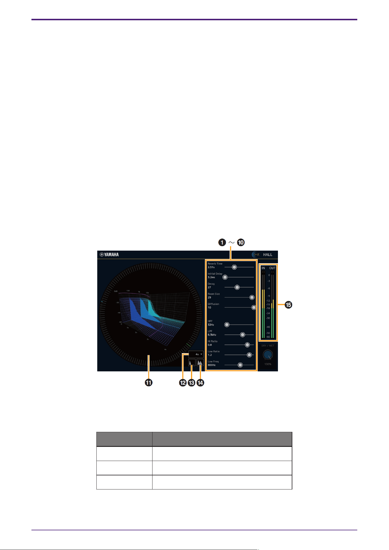
REV-X
This section uses the Hall type of REV-X as an example.
➊ Reverb Time
Adjusts the reverb time. This parameter links to Room Size.
The adjustable range varies depending on the REVX type.
REV-X type Range
Hall 0.289 sec–29.0 sec
Room 0.260 sec–26.0 sec
Plate 0.333 sec–33.3 sec
Effect
dspMixFx User Guide | 37

➋ Initial Delay
Adjusts the time that elapses between the direct, original sound and the initial reflections that follow it.
Range: 0.1 msec–200.0 msec
➌ Decay
Adjusts the characteristic of the envelope from the moment the reverberation starts to the moment it
attenuates and stops.
Range: 0–63
➍ Room Size
Adjusts the size of the simulated room. This parameter links to Reverb Time.
Range: 0–31
➎ Diffusion
Adjusts the spread of the reverberation.
Range: 0–10
➏ HPF
Adjusts the cutoff frequency of the high pass filter.
Range: 20 Hz–8.0 kHz
➐ LPF
Adjusts the cutoff frequency of the low pass filter.
Range: 1.0 kHz–20.0 kHz
➑ Hi Ratio
Adjusts the duration of reverberation in the high frequency range by using a ratio relative to the Reverb
Time. When you set this parameter to 1, the actual specified Reverb Time is fully applied to the sound. The
lower the value, the shorter the duration of reverberation in the high frequency range.
Range: 0.1–1.0
➒ Low Ratio
Adjusts the duration of reverberation in the low frequency range by using a ratio relative to the Reverb
Time. When you set this parameter to 1, the actual specified Reverb Time is fully applied to the sound. The
lower the value, the shorter the duration of reverberation in the low frequency range.
Range: 0.1–1.4
➓ Low Freq
Adjusts the frequency of the Low Ratio.
Range: 22.0 Hz–18.0 kHz
⓫ Graph
Indicates the characteristics of reverberation. The vertical axis indicates the signal level, the horizontal
axis indicates the time, and the Z-axis indicates the frequency. You can adjust the characteristics of
reverberation by dragging the handles in the graph.
⓬ Time Axis Setting
Selects the display range of the time (horizontal axis) on the graph.
Display range: 500 msec–50 sec
⓭ Zoom Out
Zooms out the display range of the time (horizontal axis) on the graph.
Effect
38 | dspMixFx User Guide

⓮ Zoom In
Zooms out the display range of the time (horizontal axis) on the graph.
⓯ Level Meters
Displays the input/output level from REV-X.
Software operation
• You can reset certain parameters to their default values by holding the [Ctrl]/[Command] key while you click on
the appropriate knobs, sliders, and faders.
• You can adjust the parameters more finely by holding the [Shift] key while you drag on the appropriate knobs,
sliders, and faders.
Effect
dspMixFx User Guide | 39
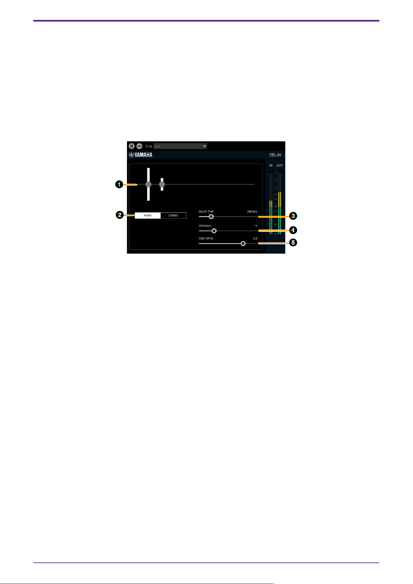
DELAY
You can select Delay as an effect type in the REV-X area.
These can be used with all sampling frequencies.
How to Open the Screen
・From dspMixFx UR-C
After Delay is selected in the REV-X area, click “REV-X Edit.”
・From Dedicated Windows for Cubase Series
Select Delay for “REV-X Type” in the effect setting area.Click “REV-X Edit” to start dspMixFx UR-C, and the
dspMixFx UR-C Delay screen will open.
➊ Graph
Visually displays Delay settings and their effects. Cannot be operated.
➋ MONO/STEREO switching
Switches the delay type.
MONO: The left and right delay times will be the same.
STEREO: This effect applies a delay alternately to the left and right. This cannot be selected when the
sampling frequency is 176.4 kHz or 192 kHz.
➌ DELAY TIME
Sets the delay time.
Range: 0.1 ms–1300.0 ms
➍ FEEDBACK
Sets the amount of delay feedback.
Range: 0–63
➎ HIGH RATIO
Sets the amount of high frequency component included in the feedback.
Range: 0.1–1.0
Effect
40 | dspMixFx User Guide
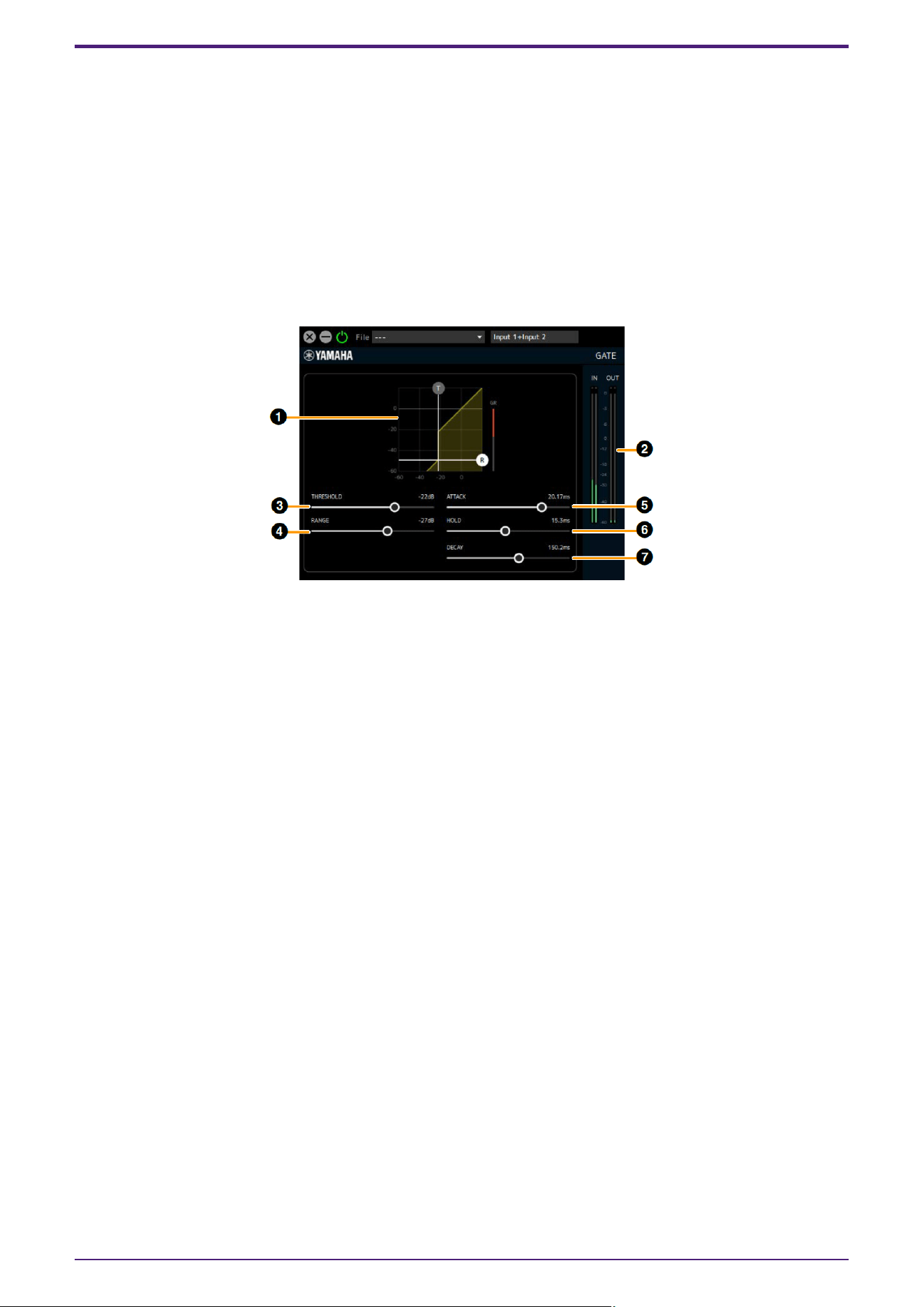
GATE
If a signal that is lower than the THRESHOLD is input, this reduces the output by a fixed value (RANGE). Use this
when you do not want environmental noise to be added to the stream. This can be used as a streaming effect in
the path from the input channel to the streaming mix, but does not affect the recording signal sent from the
channel to the DAW.
This unit has two Gates available. These can be used with all sampling frequencies.
How to Open the Screen
This is displayed when Streaming mix is selected in the dspMixFx UR-C’s MIX area, select Gate in the channel
area’s “Streaming Effect Type”, and then click “Edit effect.”
Operations cannot be performed from the Cubase series dedicated screen.
➊ Graph
This visually displays the gate’s THRESHOLD and
RANGE settings. You can also operate the (T) handle for THRESHOLD and the (R) handle for RANGE.
➋ Gain Reduction Meter
This displays the amount of gain reduction for the gate.
➌ THRESHOLD
Sets the threshold level at which the gate effect is applied.
Range: −72 dB–0 dB
➍ RANGE
Sets the amount of attenuation when the gate effect is applied.
Range: −∞, −72 dB–0 dB
➎ ATTACK
Sets how quickly the gate opens after the input signal level exceeds the THRESHOLD.
Range: 0.092 ms–80.00 ms
➏ HOLD
Sets the time to wait before the gate begins to close after the input signal level drops below THRESHOLD.
Range: 0.02 ms–1960.0 ms
➐ DECAY
Sets how quickly the gate closes after the input signal has passed the HOLD wait time.
Range: 9.3 ms–999.0 ms
Effect
dspMixFx User Guide | 41
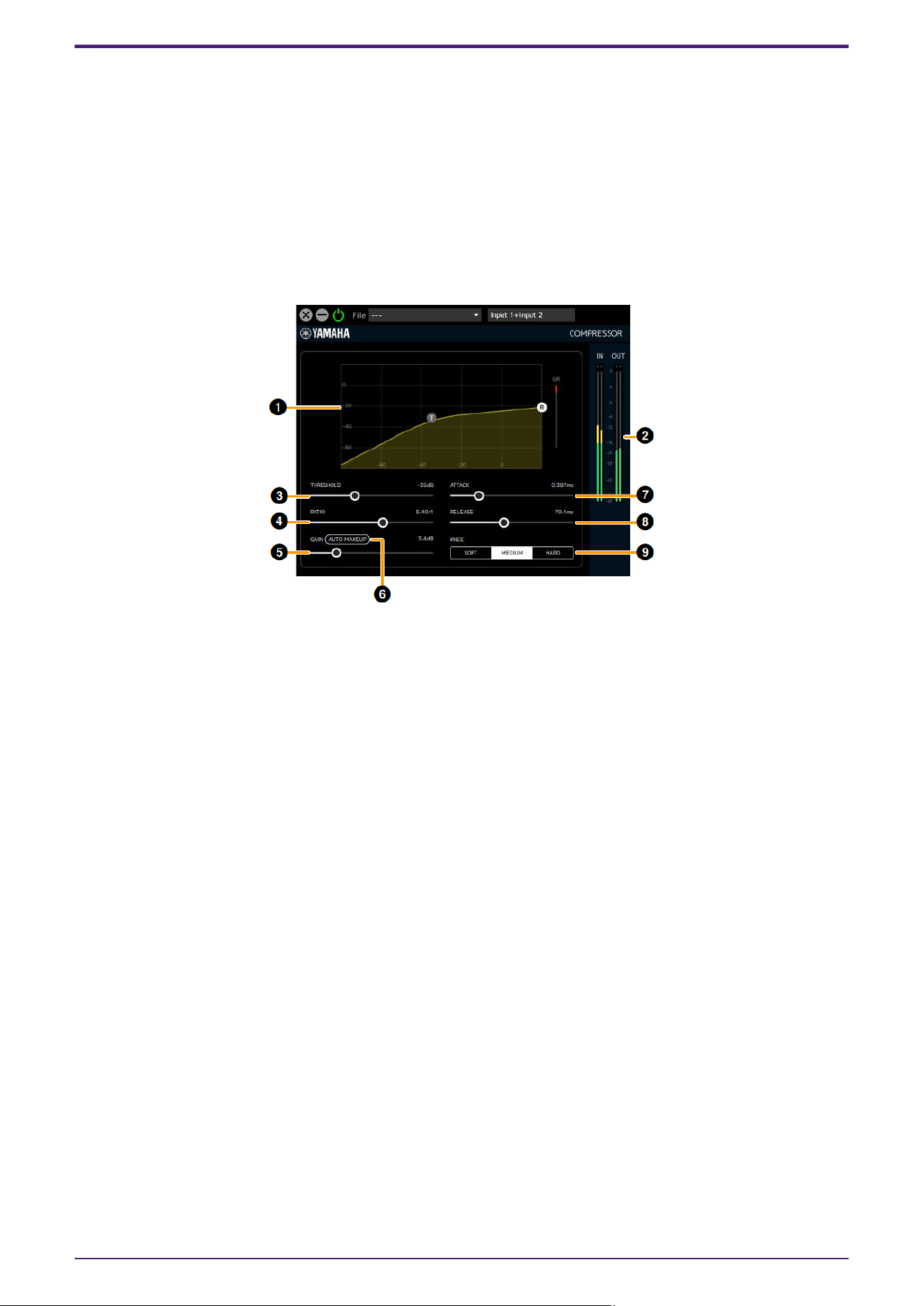
COMPRESSOR
Volume changes can be adjusted by compressing the portion of the signal level that exceeds the THRESHOLD.
This can be used as a streaming effect in the path from the input channel to the streaming mix, but does not
affect the recording signal sent from the channel to the DAW.
This unit has two Compressors available. These can be used with all sampling frequencies.
How to Open the Screen
This is displayed when Streaming mix is selected in the dspMixFx UR-C’s MIX area, select Comp in the channel
area’s “Streaming Effect Type”, and then click “Edit effect.”
Operations cannot be performed from the Cubase series dedicated screen.
➊ Graph
Visually displays the compressor’s THRESHOLD, RATIO and GAIN settings. You can also operate the (T)
handle for THRESHOLD and the (R) handle for RATIO.
➋ Gain Reduction Meter
Displays the amount of gain reduction for the compressor.
➌ THRESHOLD
Sets the threshold level at which the compressor effect is applied.
Range: −54 dB–0 dB
➍ RATIO
Sets the amount of compression for the compressor.
Range: 1.00:1–INF:1
➎ GAIN
Sets the output level of the compressor. When Auto Makeup is on, this will be set automatically and
cannot be operated.
Range: 0.0 dB–18.0 dB
➏ Auto Makeup
When set to ON, the GAIN is automatically set using the THRESHOLD and RATIO settings.
➐ ATTACK
Automatically sets the speed at which the compressor effect reaches its maximum once the input signal
level exceeds the THRESHOLD.
Range: 0.092 ms–80.00 ms
Effect
42 | dspMixFx User Guide
➑ RELEASE
This is the time it takes for the compressor effect to disappear after the input signal falls below the
THRESHOLD.
Range: 9.3ms–999.0ms
➒ KNEE
Sets the smoothness (sharpness) of volume changes near the THRESHOLD setting level.
Options Description
SOFT The volume changes naturally.
MEDIUM Between Hard and Soft.
HARD The volume changes are noticeable.
Effect
dspMixFx User Guide | 43
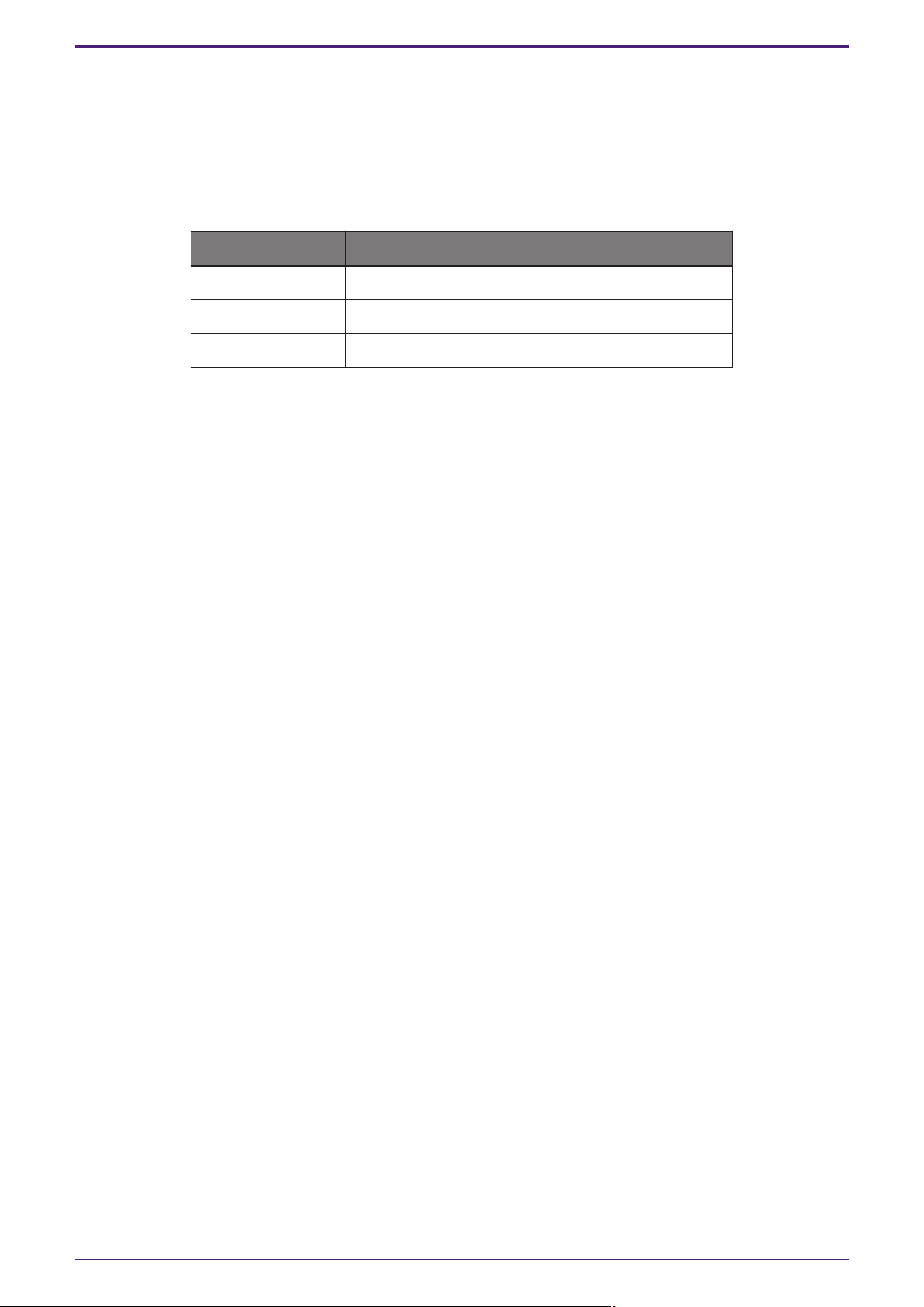
DUCKER
Automatically attenuates the sound of the DAW/Music/Voice channel for the input audio from the Input1/2 and
Voice channels. You can create an environment in which the background music is played at a low volume while
you are talking on the microphone or while you are talking from the chat application, and then the background
music is played at the original volume in all other cases.
It can be used as a streaming effect for routes from the DAW/Music/Voice channels to the streaming mix.
This unit has 2 duckers available. These can be used with all sampling frequencies.
How to Open the Screen
This is displayed when Streaming mix is selected in the dspMixFx UR-C’s MIX area, select Ducker in the
DAW/Music/Voice area’s “Streaming Effect Type”, and then click “Edit effect.”
Operations cannot be performed from the Cubase series dedicated screen.
➊ Graph
Visually displays the change in output level over time from the beginning of the Ducker effect to the end of
effect. You can also operate the (A) handle for ATTACK, the (D) handle for DECAY, and the (R) handle for
RANGE.
➋ Gain Reduction Meter
Displays the amount of gain reduction for the ducker.
➌ DUCKER SOURCE
Sets the signal used to determine the strength of the ducker.
You can configure the settings for multiple signals.
INPUT1: Signal from Input1 channel to Streaming mix (post-fader)
INPUT2: Signal from Input2 channel to Streaming mix (post-fader)
VOICE: Signal from Voice channel to Streaming mix (postfader)
➍ THRESHOLD
Sets the threshold level at which the ducker effect is applied.
Range: −60 dB–0 dB
➎ RANGE
Sets the amount of attenuation when the ducker effect is applied.
Range: −70 dB–0 dB
Effect
44 | dspMixFx User Guide

➏ ATTACK
Sets how quickly the volume lowers after the input signal level exceeds the THRESHOLD.
Range: 0.092 ms–80.00 ms
➐ DECAY
Sets how quickly the volume returns after the input signal level falls below the THRESHOLD.
Range: 1.3 ms–5.0 s
Effect
dspMixFx User Guide | 45
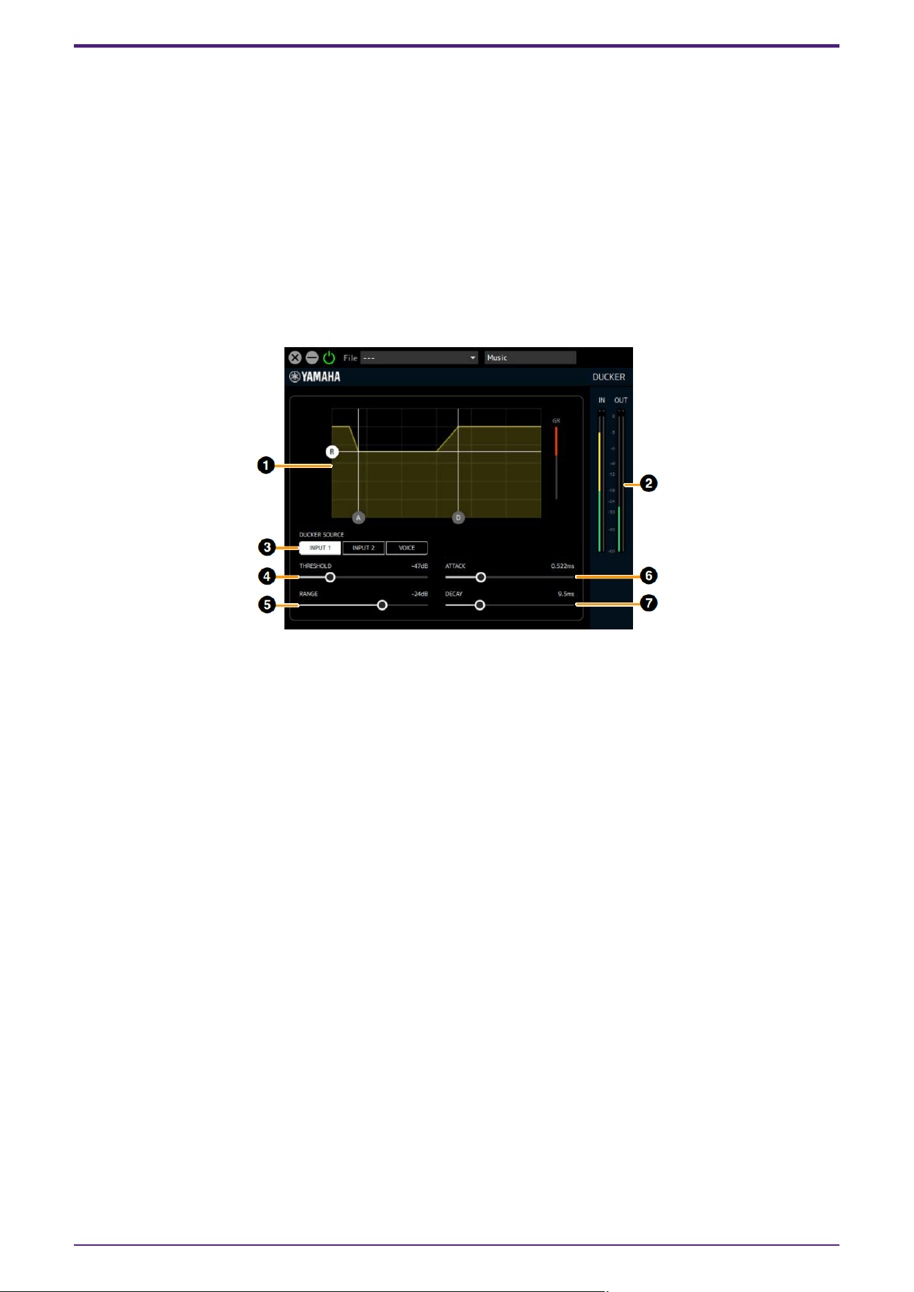
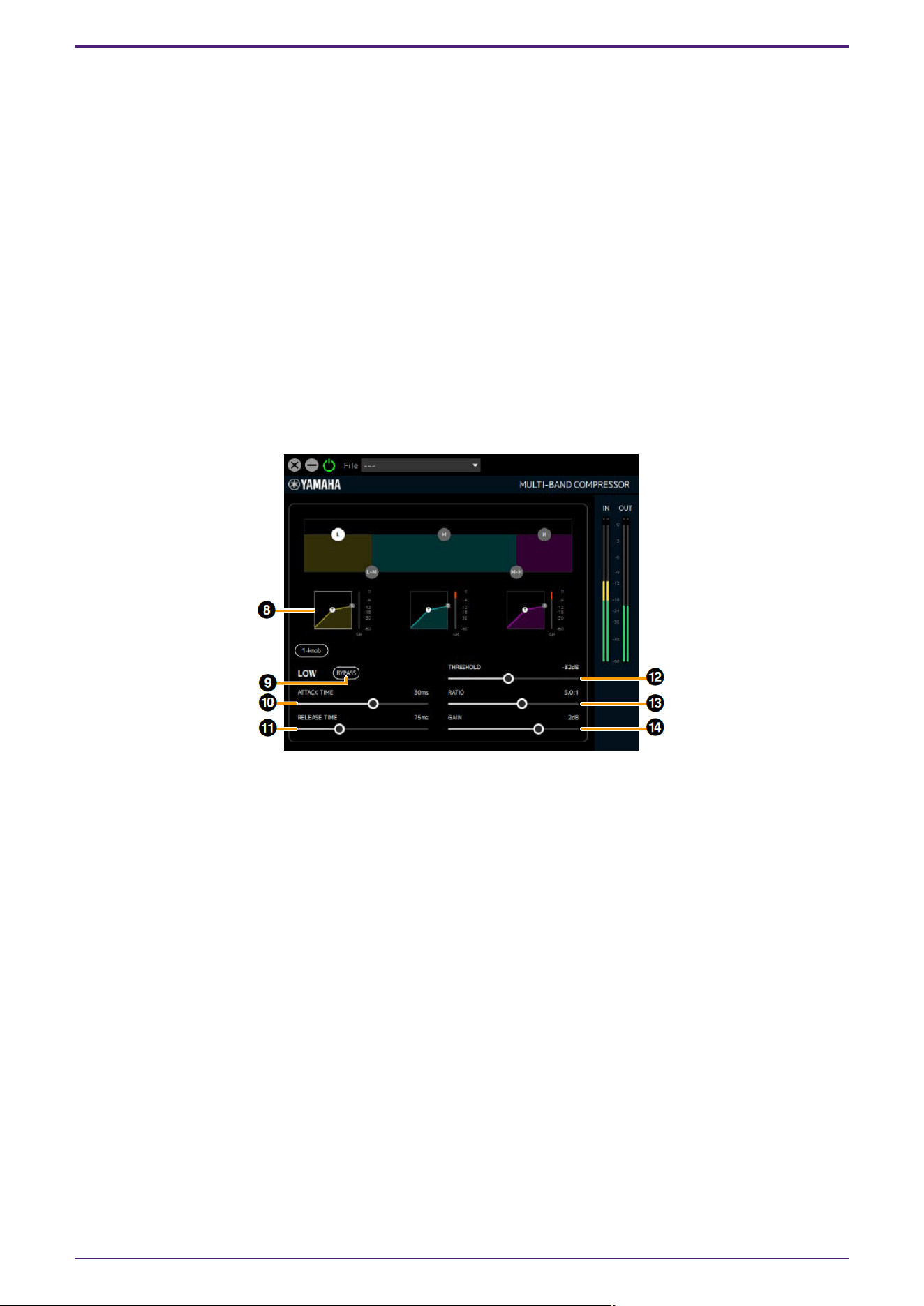
MULTI-BAND COMPRESSOR
By using a multi-band compressor algorithm and setting the compressor for each LOW/MID/HIGH band, you can
suppress changes in the stream volume and increase the sound pressure.
Can be used at the final output stage of a streaming mix.
This can be used when the sampling frequency is 44.1 kHz, 48 kHz, 88.2 kHz or 96 kHz.
How to Open the Screen
This is displayed when Streaming mix is selected in the dspMixFx UR-C’s MIX area, then select M.B. Comp in the
channel area’s “Streaming Effect Type”, and then click “Edit effect.”
Operations cannot be performed from the Cubase series dedicated screen.
[When Graph (Band Division Overview) is clicked]
➊ Graph (Band Division Overview)
Sets the band division for each of the LOW/MID/HIGH bands and displays the level of each band in
simplified form.
Use the (L) handle to set LOW GAIN, the (M) handle to set MID GAIN, and the (H) handle to set HIGH GAIN.
The L-M XOVER settings can be operated using the (L-M) handle and the M-H XOVER settings can be
operated using the (M-H) handle.
Click this area to display the parameters for ➌-➐ below.
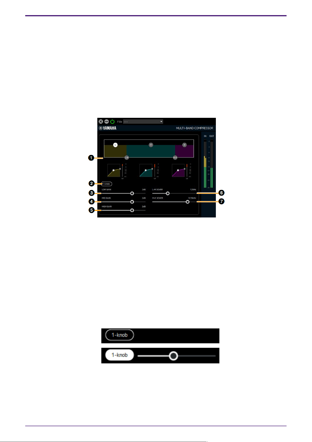
➋ 1-knob
This function controls the effect of Multi-Band Compressor with a single slider. When 1-knob is turned on,
a slider will appear, and you can operate the slider to control THRESHOLD, RATIO, and GAIN of each band.
ATTACK, RELEASE and XOVER frequencies are fixed values. 1-knob will be displayed when you click on
any graph.
[When 1-knob is off]
[When 1-knob is on]
➌ LOW GAIN
Sets the volume of the LOW band.
Range: −∞, −60 dB–+18 dB
Effect
46 | dspMixFx User Guide
➍ MID GAIN
Sets the volume of the MID band.
Range: −∞, −60 dB–+18 dB
➎ HIGH GAIN
Sets the volume of the HIGH band.
Range: −∞, −60 dB–+18 dB
➏ L-M XOVER
Sets the crossover frequency between the LOW band and MID band.
Range: 21.2 Hz–4.00 kHz
➐ M-H XOVER
Sets the crossover frequency between the MID band and HIGH band.
Range: 42.5 Hz–8.00 kHz
[When LOW band graph is clicked]
➑ LOW Band Graph
Visually displays the LOW band compressor’s THRESHOLD, RATIO and GAIN settings. You can also
operate the (T) handle for THRESHOLD and the (R) handle for RATIO. Also displays a gain reduction meter
to the right of the graph. Also displays a gain reduction meter to the right of each graph. Click this area to
display the parameters for ➒–⓮ below.
➒ BYPASS (LOW)
Turns the LOW band compressor bypass on or off.
➓ ATTACK TIME (LOW)
Sets the LOW band compressor attack time.
Range: 1 ms–200 ms
⓫ RELEASE TIME
Sets the compressor (Common to all bands) release time.
Range: 10 ms–3000 ms
⓬ THRESHOLD (LOW)
Sets the LOW band compressor THRESHOLD.
Range: −54 dB–−6 dB
Effect
dspMixFx User Guide | 47
⓭ RATIO (LOW)
Sets the LOW band compressor RATIO.
Range: 1.0:1–20.0:1
⓮ GAIN (LOW)
Same as ➌.
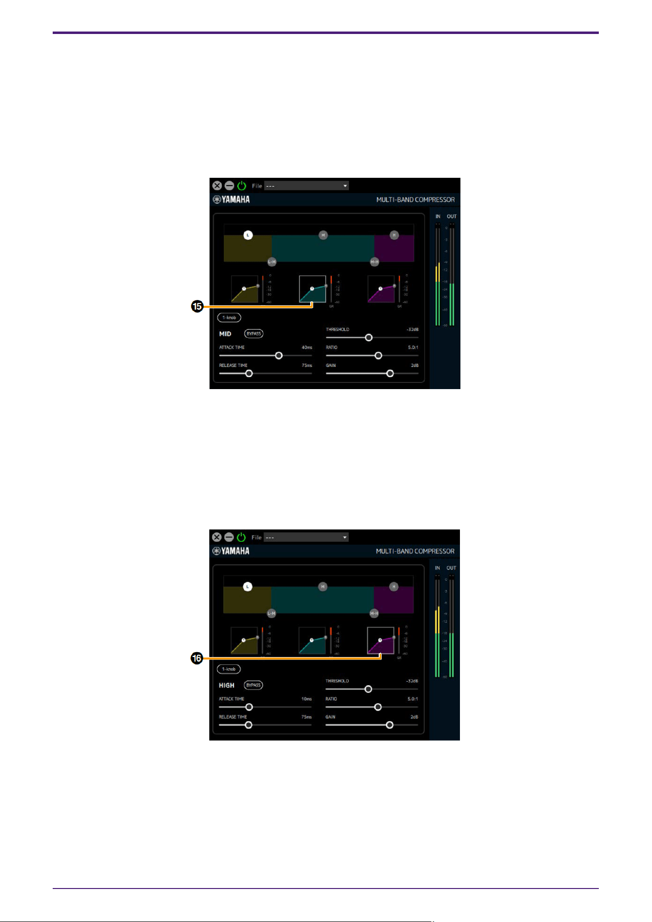
[When MID band graph is clicked]
⓯ MID Band Graph
Visually displays the MID band compressor’s THRESHOLD, RATIO and GAIN settings. You can also
operate the (T) handle for THRESHOLD and the (R) handle for RATIO. Also displays a gain reduction meter
to the right of the graph. Also displays a gain reduction meter to the right of each graph. Clicking on this
area displays the parameters of the MID band compressor. (The details for each parameter are the same
as for the LOW band.)
[When HIGH band graph is clicked]
⓰ HIGH Band Graph
Visually displays the HIGH band compressor’s THRESHOLD, RATIO and GAIN settings. You can also
operate the (T) handle for THRESHOLD and the (R) handle for RATIO. Also displays a gain reduction meter
to the right of the graph. Clicking on this area displays the parameters of the HIGH band compressor. (The
details for each parameter are the same as for the LOW band.)
Effect
48 | dspMixFx User Guide
DAW Software
Cubase AI allows you to record and edit audio through dspMixFx. For detailed instructions, refer to the “Cubase
AI Operation Manual” on the Steinberg website.
If you are using DAW software other than the Cubase series, refer to the User Guide for your UR-C/URX-C series
device for setup instructions.
Dedicated Windows for Cubase Series (DAW)
These are the windows for configuring the device settings from Cubase series software. The dedicated windows
for Cubase series allow you to configure the parameters which are configured by dspMixFx UR-C. Two types of
windows are available: Input Settings and Hardware Setup.
Input Settings Window Hardware Setup Window
How to Open the Window
Input Settings Window
In the Cubase series menu, select [Project] → [Add Track] → [Audio] to create an audio track, and then click the
[URxxC] tab displayed in the inspector on the left side of the screen. (xx will be replaced with the model name of
your device.)
Hardware Setup Window
・ From the Cubase series menu
Select [Studio] → [Studio Setup], then select the [Steinberg UR-C] on the [Steinberg I/O] on the left side.
・ From Input Settings Window
Open the Input Settings Window and click [Hardware Setup] in the header area.
DAW Software
dspMixFx User Guide | 49
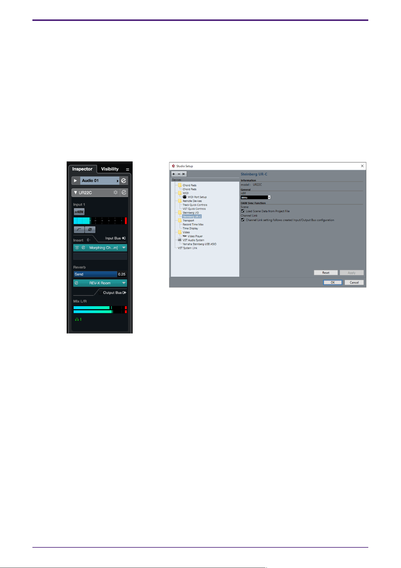
Input Settings Window
This window is for configuring the input settings of the device. The signal flow is from top to bottom. The
settings on this window (except for the +48V indicator) are saved to the Cubase project file.
The Input Settings Window is displayed on the audio track routing as URxxC. (xx will be replaced with the model
name of your device.)
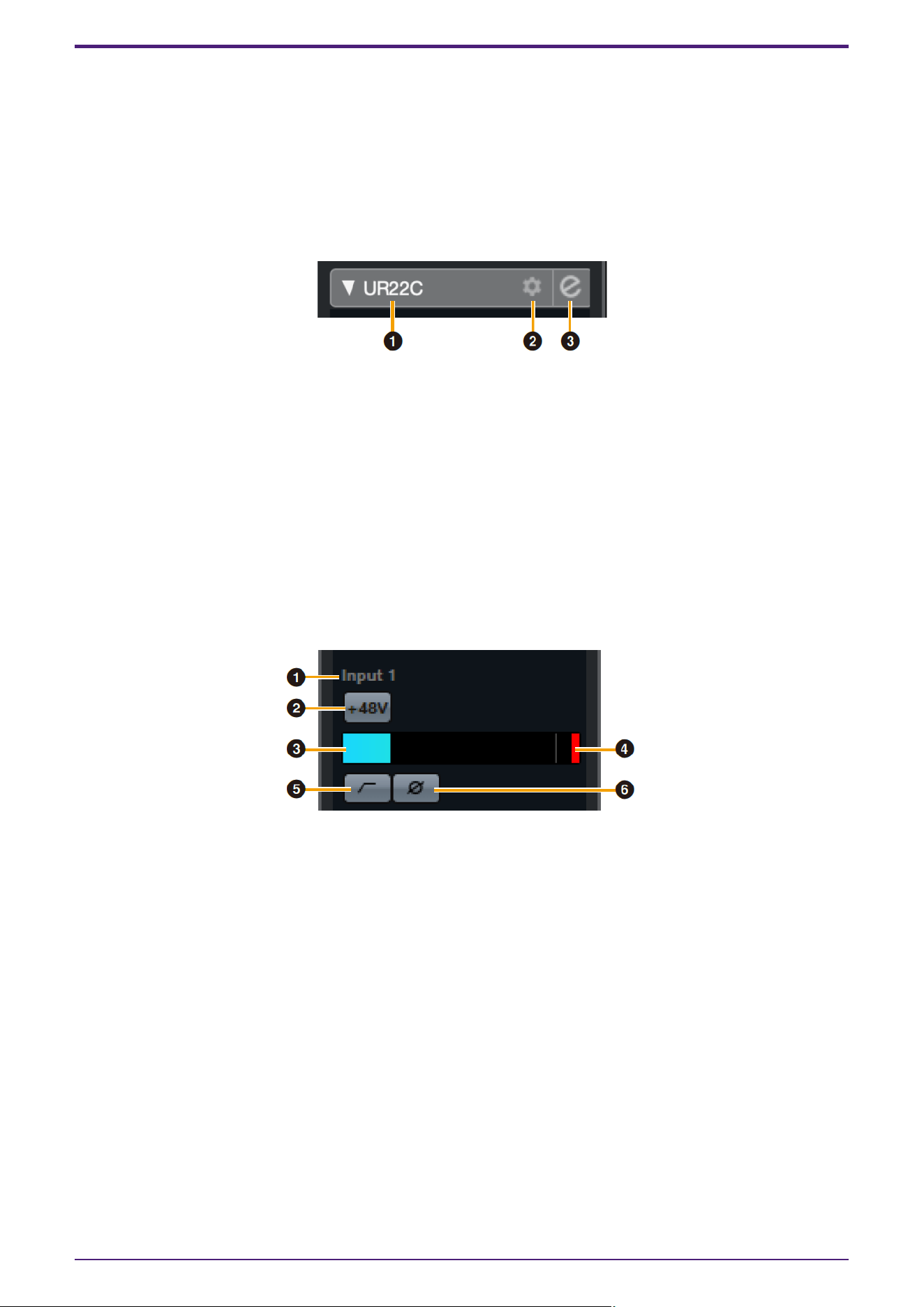
Header Area
Displays the names of connected devices and opens/closes the Editor.
➊ model
Displays the model name (URxxC) in use. Switch between displayed or not displayed for the Input Settings
Window by clicking it.
➋ Hardware setup
Opens the Hardware Setup Window.
➌ Editor Active
Opens dspMixFx UR-C.
Hardware Inputs Settings area
This area is used to set parameters related to the UR44C inputs.
➍ Port name
Displays the name of the port which is being used for input to the track of the device.
➎ +48V
Indicates the on (lit) and off (unlit) status of the phantom power function of the device.
➏ Input meter
Displays input levels.
➐ Meter Clip
Displays the input meter clip when clipping occurs. Click this to stop this display.
➑ High Pass Filter
Turns on (lit) and off (unlit) the high pass filter (URX44C: Not available on [LINE INPUT 5/6]).
To select the cutoff frequency of the high pass filter, use the “Hardware Setup Window” in the section
“dspMixFx UR-C.”
DAW Software
50 | dspMixFx User Guide
➒ Phase
Switches phase inversion on (lit) and off (unlit). Shows L, R when stereo is selected.
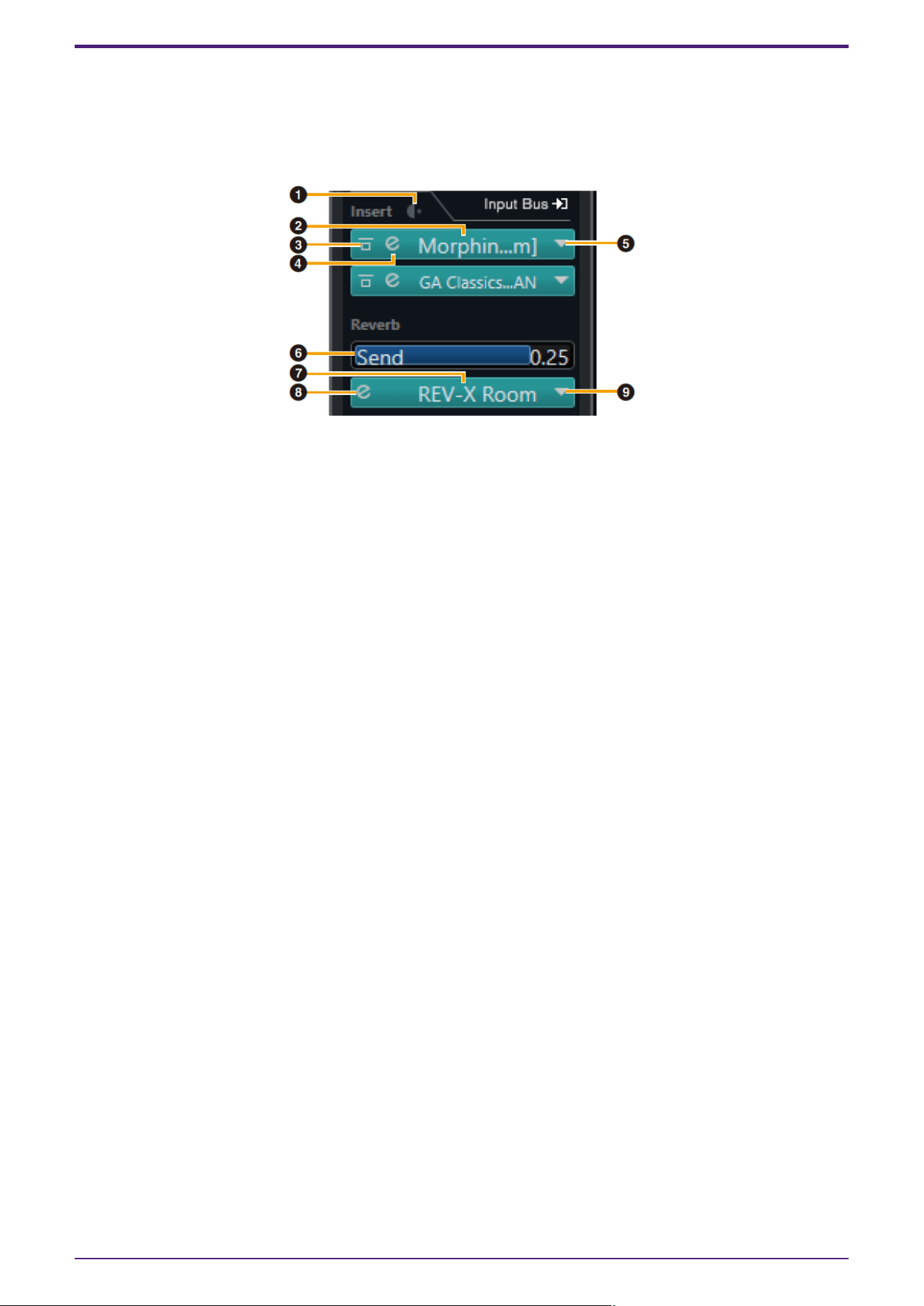
Effect Settings area
This area is used to set parameters related to the UR44C input/output port effects.
➊ Pre/Post
Used to select the insertion point for the effect.
➋ Effect Name
Displays the names of the applied effects.
➌ Effect Bypass
Enables/bypasses the effect.
➍ Effect Edit
Displays the Effect Edit window.
➎ Effect Type
Selects the effect type.
Settings: No Effect, Ch.Strip, Clean, Crunch, Lead, Drive, Pitch Fix
NOTE
The maximum number of effects that can be used simultaneously is limited.Refer to “Limitations on the
use of effects” in the User Guide for your UR-C/URX-C series device.
➏ REV-X Send
Adjusts the signal level which is sent to REV-X.
Range: −∞ dB–+6.00 dB
➐ REV-X Name
Displays the selected REV-X type.
➑ REV-X Edit
Opens the “REV-X” setup window.
➒ REV-X Type
Selects the REV-X type.
Settings: Hall, Room, Plate, Delay
DAW Software
dspMixFx User Guide | 51
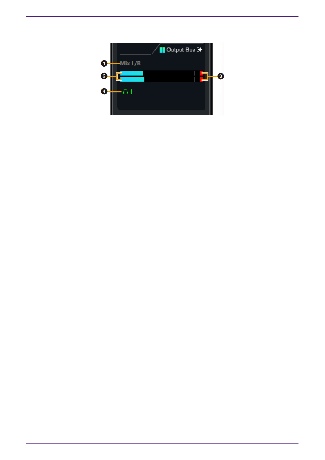
Outputs area
This area is used to set parameters related to hardware outputs.
➊ Mix Bus name
Displays the Mix Bus name of the hardware output. The output bus of the track must be connected to this
Mix bus.
➋ Output meter
Displays meters for the hardware Mix Bus connected to hardware outputs.
➌ Meter Clip
Displays the input meter clip when clipping occurs. Click this to stop this display.
➍ Headphones
UR22C/URX22C: Headphone 1 is on at all times.
UR44C/URX44C/UR816C: Patches headphones to the hardware Mix Bus connected to hardware outputs.
DAW Software
52 | dspMixFx User Guide
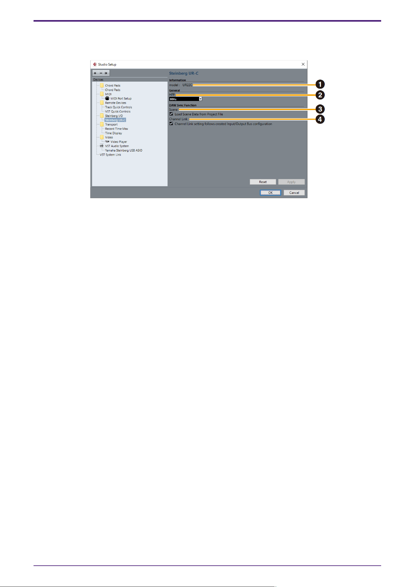
Hardware Setup Window
This window allows you to configure general hardware settings and Cubase-linked function settings.
➊ model
Displays the name of the device.
➋ HPF
Selects the cutoff frequency of the high pass filter (URX44C: Not available on [LINE INPUT 5/6]).
Settings: 120 Hz, 100 Hz, 80 Hz, 60 Hz, 40 Hz
➌ Scene
When a Cubase project file that includes scenes for the device is imported, the scene information is
automatically applied to the device.
NOTICE
Data saved to the device will be overwritten.
➍ Channel Link
Automatically configures stereo links based on the bus configuration in use.
DAW Software
dspMixFx User Guide | 53
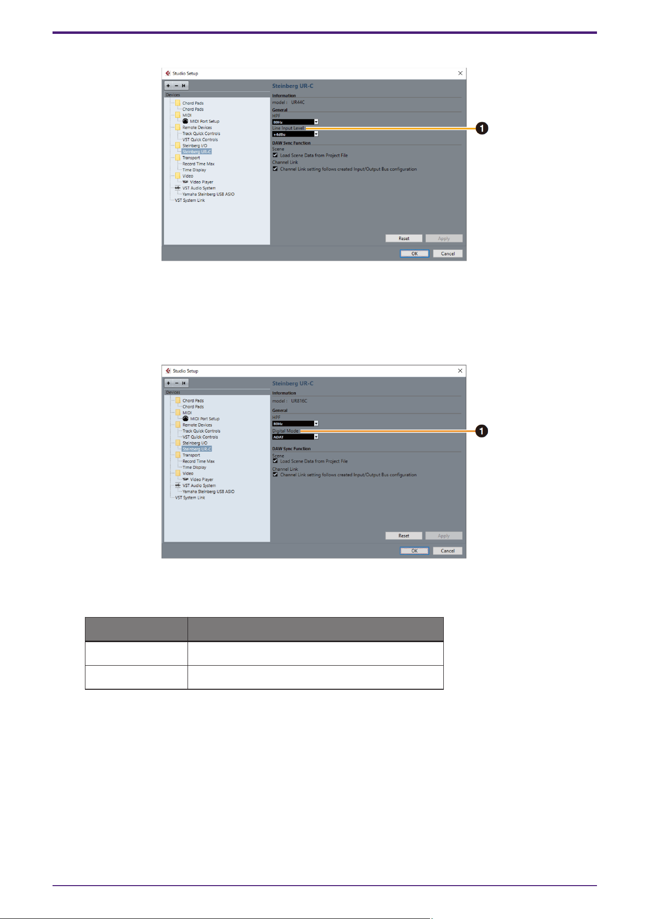
UR44C/URX44C only
➊ LINE Input Level
Selects the input signal level of [LINE INPUT 5/6].
Options: +4 dBu, −10 dBV
UR816C only
➊ Digital Mode
Selects the input and output signal format of the [OPTICAL IN] and [OPTICAL OUT] jack.
Options Description
ADAT Input and output signals of up to 8 channels.
S/PDIF Input and output 2 channel signals.
With the ADAT format, the number of channels for input and output signals varies depending on the
sampling frequency.
44.1 kHz/48 kHz: 8 channels
88.2 kHz/96 kHz: 4 channels
176.4 kHz/192 kHz: 2 channels
With the S/PDIF format, a 2-channel signal is input and output at all sampling frequencies.
DAW Software
54 | dspMixFx User Guide
Update
Updating the Firmware
You can update the firmware for a UR-C/URX-C device from dspMixFx UR-C.
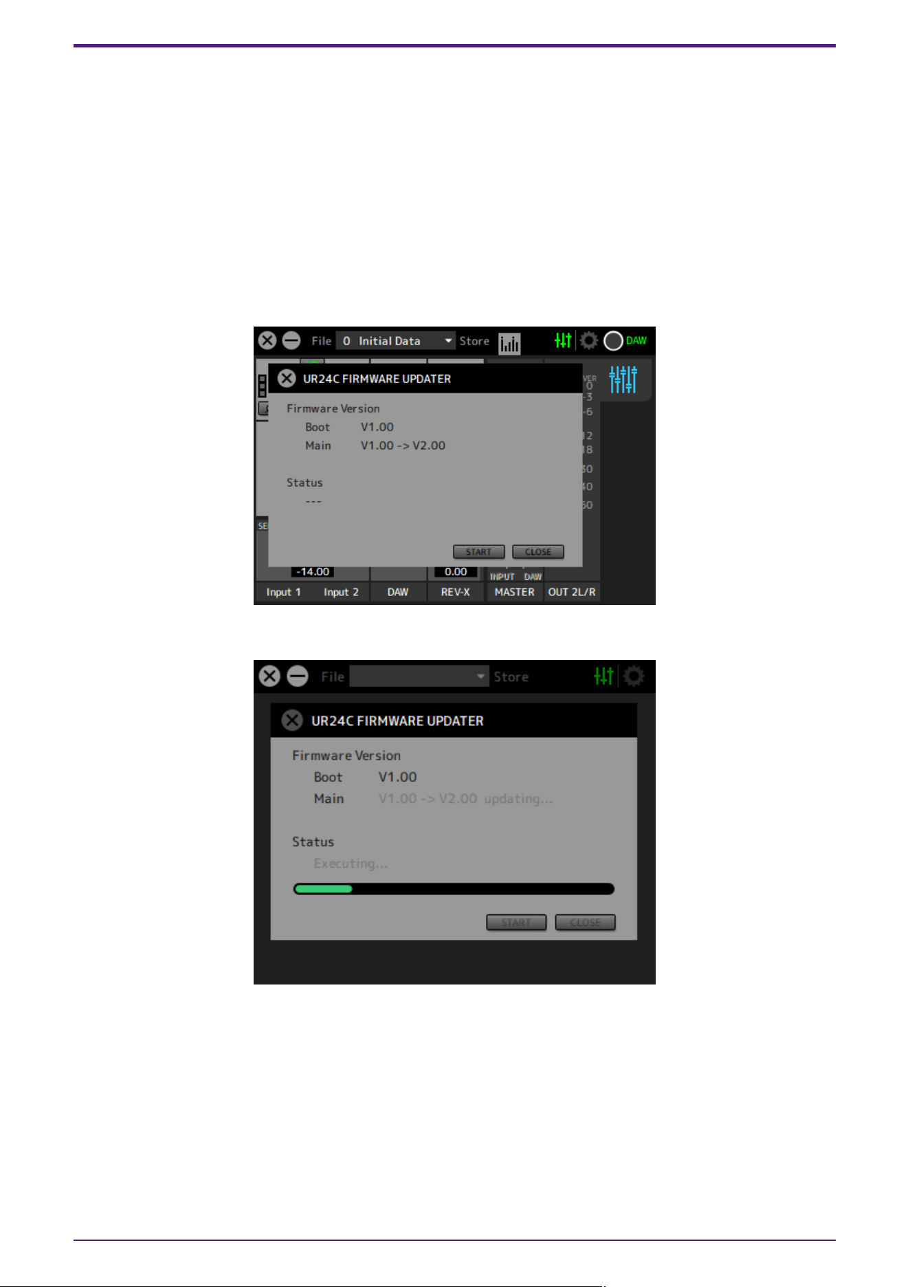
1. Connect a UR-C/URX-C device with a firmware version older than the firmware version for dspMixFx UR-C
installed on your computer. After connecting the device, the FIRMWARE UPDATER window will open
automatically.
NOTE
If you want to cancel the update, click the [CLOSE] button.
2. Click the [START] button to start the firmware update.
Update
dspMixFx User Guide | 55
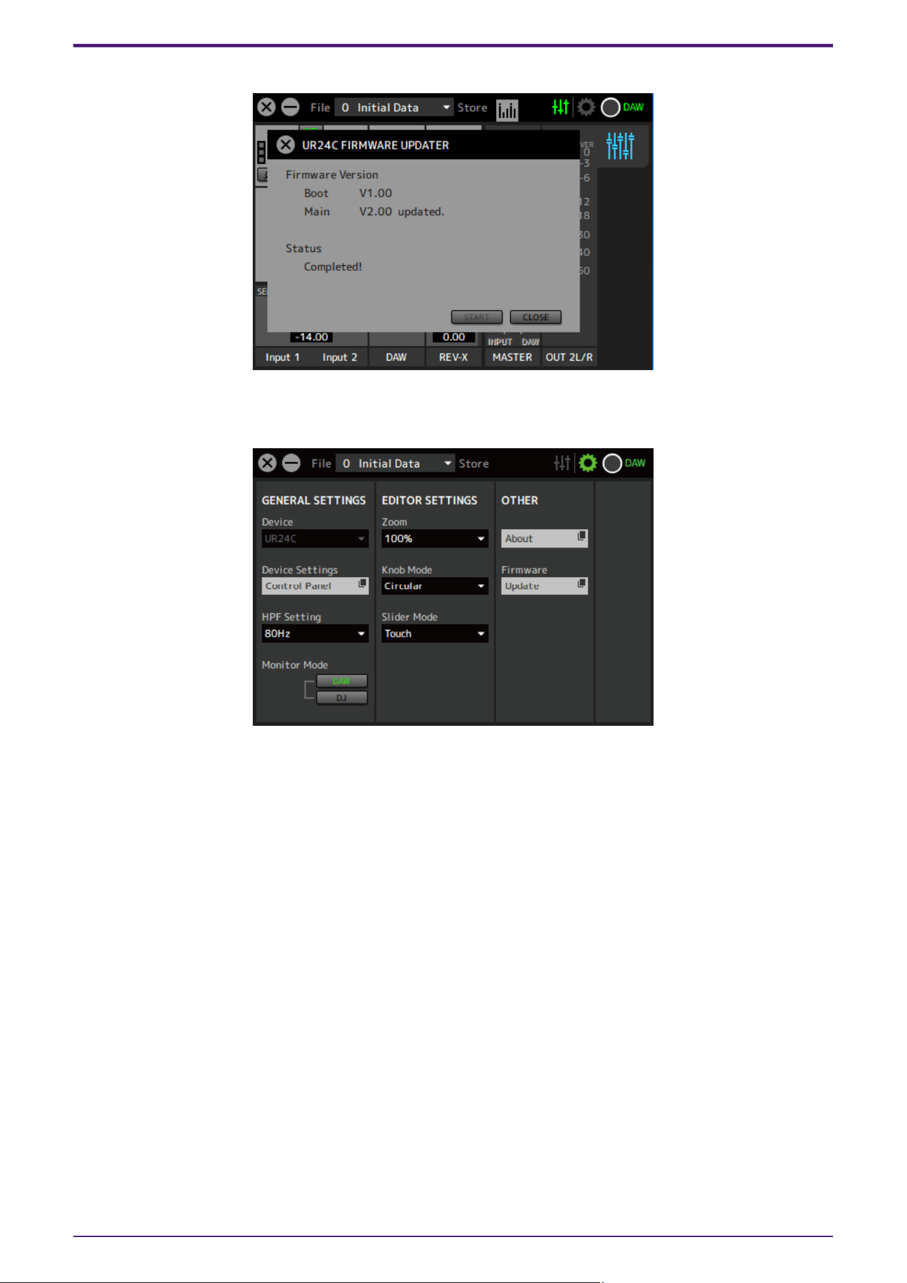
3.After the update is complete, press the [CLOSE] button to close the screen.
NOTE
If you cancel in step 1, you can always update the firmware from [Firmware] on the setup screen.
Update
56 | dspMixFx User Guide

© 2025 Yamaha Corporation
Published 09/2025
YJ-A0