EN
Original Instructions
Version 1
CAN BUS 13 AND 7 PIN
TOWBAR
SOCKET
TESTER
27198
1. Preface
– 2 –
EN
These are the original product instructions. This document is part of the product; retain it for the life of the
product, passing it on to subsequent holders. Read this manual in full before attempting to assemble,
operate or maintain this product.
1.1 Product Reference
User Manual for: CAN Bus 13 and 7 Pin Towbar
Socket Tester
Stock No: 27198
Part No: TST13C
1.2 Revisions
Version 1: April 2024
First release
As our manuals are continually updated, always ensure
that the latest version is used.
Please visit drapertools.com/manuals for the latest
version of this manual and the associated parts list,
if applicable.
1.3 Understanding the Safety Content
of This Manual
WARNING!
– Situations or actions that may
result in personal injury or death.
CAUTION! – Situations or actions that may
result in damage to the product or surroundings.
Important: – Information or instructions of particular
importance.

– 3 –
EN
Stock No. 27198
Part No. TST13C
Power Supply 12V DC
Test System CAN BUS
Connection 7-pin & 13-pin
Cable Length 5m
Cable Diameter 9mm
Dimensions (LxWxH) 140 x 90 x 35mm
Net Weight 1kg
2.2 Specication
2.1 Intended Use
This towing socket tester is designed to test bulbs,
indicators and diagnose wiring faults on 12 volt
controller network (CAN BUS) systems on towing
vehicles. Suitable for quickly and easily testing 7 pin
and 13 pin sockets tted to the rear of vehicles.
Compatible with cars, 4x4’s, caravans, trailers and light
commercial vehicles.
Any other application beyond the conditions established
for use will be considered misuse. Draper Tools accepts
no responsibility for improper use of this product.
This product is intended for domestic and infrequent
light-duty trade use.
2. Product Introduction

– 4 –
EN
Important: Read all the Health and Safety instructions
before attempting to operate, maintain or repair this
product. Failure to follow these instructions may result in
injury or damage to the user, the product or the vehicle.
• Ensure all Health and Safety, Local Authority and
general workshop regulations are followed when
using this tester.
• DO NOT connect or disconnect the tester when the
ignition is turned on or the engine is running.
• ALWAYS remove the tester after use and ensure all
wiring is reconnected correctly.
• Keep this product in good working order and
condition. DO NOT operate if any parts are
damaged or missing as this may cause failure
and/or personal injury.
• DO NOT modify any parts and only use accessories
and spare parts supplied by Draper Tools.
• Keep this product out of reach of children and keep
children and unauthorised persons away from the
work area.
• Keep the work area clear and ensure that there is
adequate lighting.
• DO NOT immerse this device in water or expose it to
wet or damp conditions.
• DO NOT use the tester to perform a task for which it is
not designed.
• DO NOT expose the tester to strong sunlight or dust.
• Take care when using the tester and avoid strong
impacts or shocks.
• DO NOT disassemble the tester. The tester must be
checked by qualied service personnel only.
3.1 Explanation of symbols
Read the instruction manual
Warning!
WEEE –
Waste Electrical & Electronic Equipment
Do not dispose of this product with domestic waste
European conformity
UK Conformity Assessed
3. Health and Safety Information
– 5 –
EN
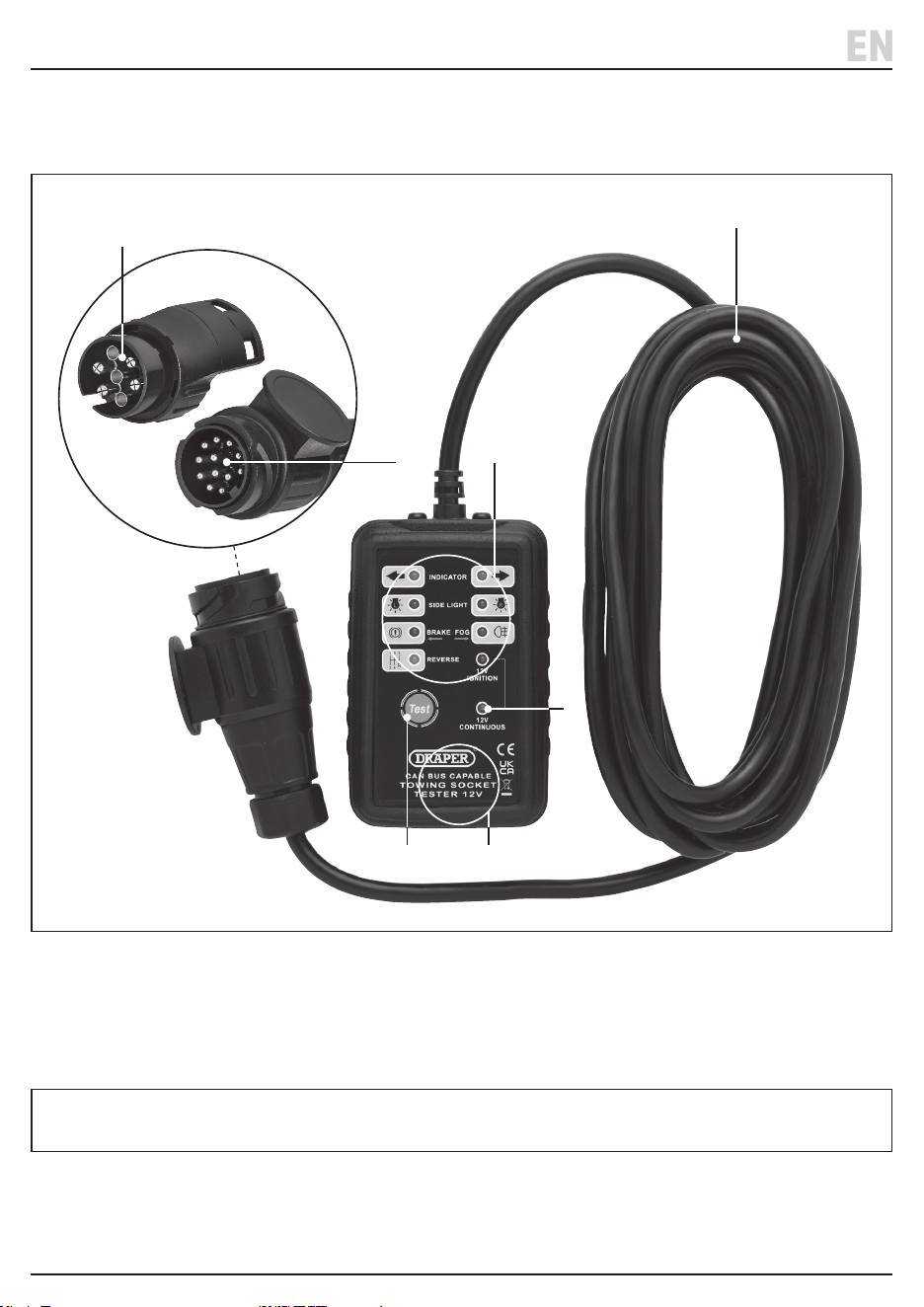
Please visit drapertools.com for our full range of accessories and consumables.
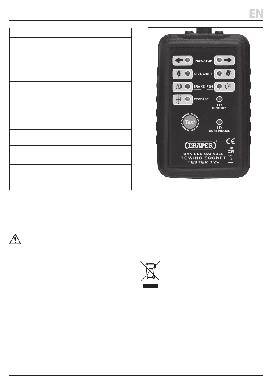
(1) Test button
(2) 13-pin connector
(3) 7-pin connector
(4) Test indicator lights
(5) Connector cable
(6) Resistive load area
(7) 12V continuous indicator light
Carefully remove the product from the packaging and examine it for any signs of damage that may have occurred
during shipment. If any part is damaged or missing, do not attempt to use the product. Please contact the Draper
Helpline; contact details can be found at the back of this manual.
4. Product Overview
(3)
(5)
(4)
(2)
(7)
(1) (6)
– 6 –
EN
5. Operating Instructions
Important: Before operating this product, read and
understand all the safety instructions listed in this
manual. Ensure that the product is fully assembled and
correctly prepared for use.
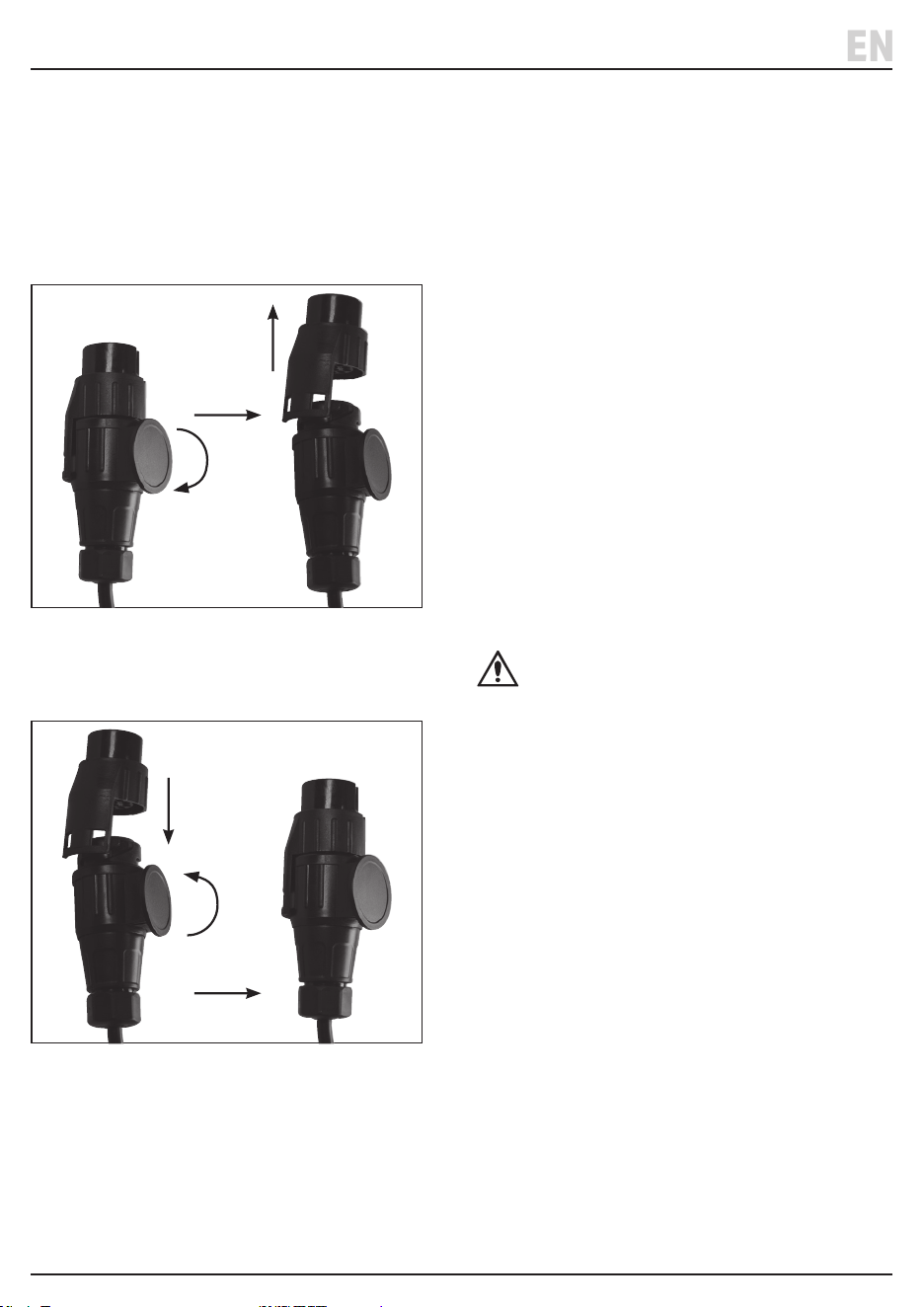
5.1 Selecting the Connector Adaptor
• To select the 13-pin adaptor – twist the outer ring
clockwise and lift o the 7-pin adaptor.
1 Fig.
• To select the 7-pin adaptor – t the 7-pin adaptor
to the 13-pin adaptor and twist the outer ring
anti-clockwise to lock in place.
2 Fig.
5.2 Operating the Tester
• Ensure the ignition and engine is switched o
before attaching the connector.
• The tester has a resistive tester internally load area (6)
which generates some heat during operation.
DO NOT hold this area for a long time and allow the
tester to cool down after 15 minutes of operation.
1. Connect the tester to the vehicle towing socket.
Take care to align the connector with the socket
before insertion.
2. Twist the outer plug ring clockwise to lock the
adaptor plug in place.
• Note: The cable supplied should be long enough
to allow the test to be carried out while sitting in
the vehicle.
• When the tester socket is correctly connected,
the vehicle’s self-test may operate and the LED lights
turn on sequentially. Carry out the manual test once
this is completed.
3. If the 12V power supply of the socket is working
correctly, the ‘12V Continuous’ indicator light (7)
will come on.
4. Then press the ‘TEST’ button (1) to carry out the
self-test to check the tester’s circuit and LED
indicators are working correctly.
CAUTION!
• The self-test only operates with the 13-pin socket.
The self-test is not available with the 7-pin adaptor as
there in no continuous feed via the 7-pin socket.
• If the vehicle has a towbar electrics self-test function,
the tester indicators may ash during the self-test
process. However, when carrying out the test with the
ignition on the indicators will function correctly.
• The tester when connected will draw the same power
from the vehicle’s battery as a vehicle light. Do not
connect the tester for longer than necessary to avoid
draining the battery.
5. Turn the vehicle’s ignition to the ‘ON’ position,
but DO NOT start the engine. The ‘12V IGNITION’
indicator will come on.
6. The indicator and lights can be operated and checked
in turn. The corresponding indicators will come on if
functioning correctly.
7. When testing is complete turn o the ignition.
Remove the tester by twisting the outer ring
anticlockwise to unlock the plug.
– 7 –
EN
5. Operating Instructions
WARNING! Do not attempt to repair or service
this product. Any servicing or repairs must be
carried out by a qualied person.
• Clean the tester frequently to maintain the tester in
good condition.
• Clean the case with a dry cloth.
• Store the tester in a safe and dry area out of the reach
of children.
• At the end of its working life, dispose of the product
responsibly and in line with local regulations.
Recycle where possible.
• DO NOT dispose of this product with domestic waste;
most local authorities provide appropriate
recycling facilities.
6. Maintenance, Storage and Disposal
Lifetime warranty - Visit drapertools.com/warranty for full details.
7. Warranty
13-Pin & 7-Pin Function Table
Wiring Description/function 13-Pin 7-Pin
1
Left hand indicator
✓ ✓
2
Fog light
✓ ✓
3
Earth (terminal 1-6
return path)
✓ ✓
4
Right hand indicator
✓ ✓
5
Right hand side/tail light
✓ ✓
6
Brake light
✓ ✓
7
Left hand side/tail light
✓ ✓
8
Reversing light
✓ ✗
9
VBAT/Permanent light
(CONTINOUS)
✓ ✗
10
Ignition indicator
✓ ✗
11
Earth for terminal 10
✓ ✗
12
Not normal used
✓ ✗
13
Earth for terminal 9
(terminal 10 return path)
✓ ✗
3 Fig.

© Published by Draper Tools Limited© Published by Draper Tools Limited
Delta International
Delta International BV
Oude Graaf 8
6002 NL
Weert
Netherlands
Contact Details
Draper Tools
Draper Tools Limited
Hursley Road
Chandler’s Ford
Eastleigh
Hampshire
SO53 1YF
UK
Website: drapertools.com
Email: [email protected]
Product Helpline: +44 (0) 23 8049 4344
Telephone Sales Desk: +44 (0) 23 8049 4333
General Enquiries: +44 (0) 23 8026 6355
General Fax: +44 (0) 23 8026 0784
Please contact the Draper Tools Product Helpline for repair and servicing enquiries.
