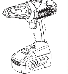
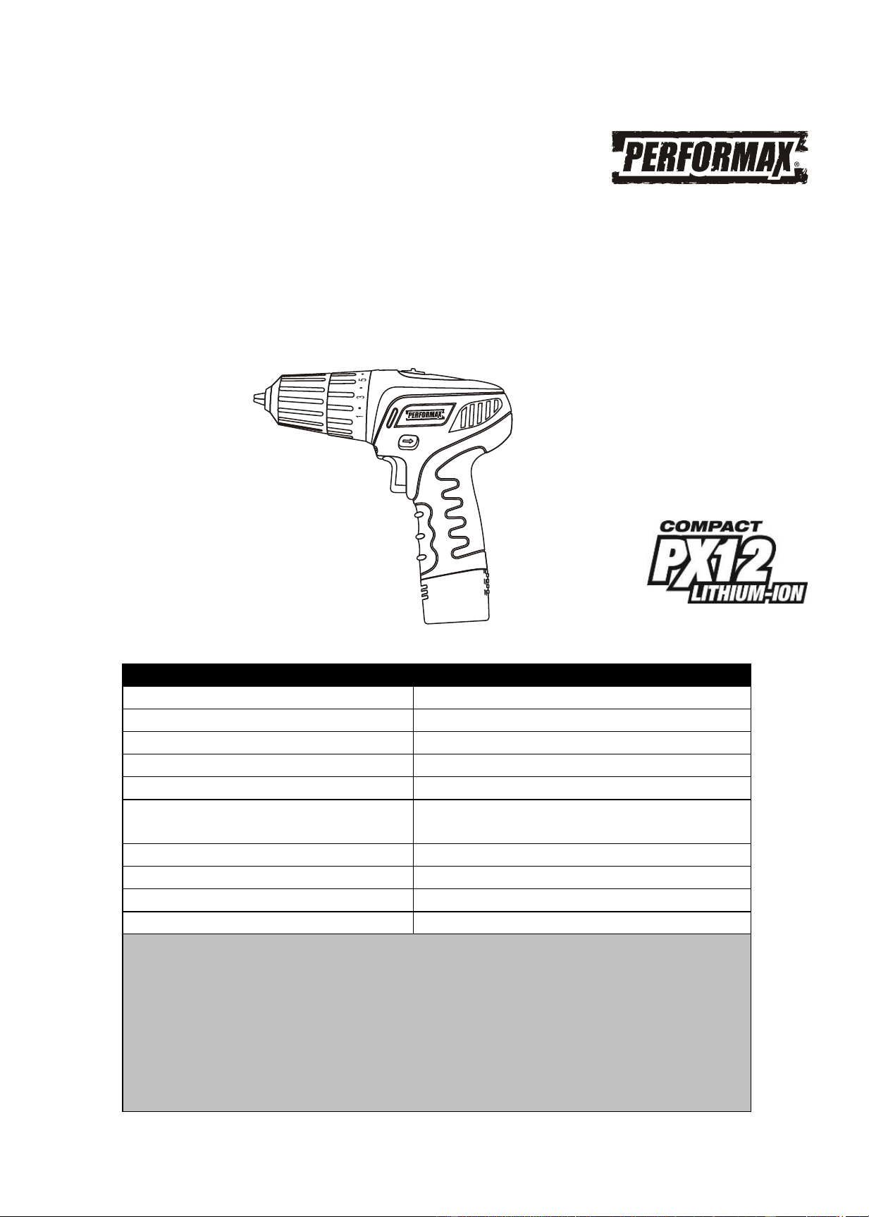
12-volt 3/8" Cordless Compact Drill
241-0502
Owner’s Manual
PRODUCT SPECIFICATIONS
Battery:
12 V, 1.5 Ah Li-ion
Maximum torque:
150 in-lb
Variable speed ranges
0–350 & 0–1050 RPM (no load)
Torque clutch positions:
16 + drill mode
Keyless chuck:
3/8" (10 mm) single sleeve
Maximum drilling depth:
1/8" (3 mm) in steel
17/32" (20 mm) in wood
Charger:
50 minute diagnostic, Class 2
Charger input:
120 V AC, 60 Hz
Charger output:
12 V DC, 2.2 A (maximum)
Weight:
2 lb 6 oz (1.1 kg) with battery
Need Assistance?
Call us on our toll free customer support line:
1-866-349-8665
Technical questions
Replacement parts
Parts missing from package
Downloaded from www.ManualsFile.com manuals search engine

2
Product specifications ………….…………………………………………………….
1
Table of contents ……………………………………………………………………...
2
General safety warnings ……………………………………………………………..
3–4
Eye, ear & lung protection ……………………………………………………………
3–4
Electrical safety ……………………………………………………………………….
4
Power tool safety ……………………………………………………………………...
5–7
General safety rules …………………………………………………………………..
5
Work area ………………………………………………………………….…………..
5
Electrical safety ……………………………………………………………………….
5
Personal safety ………………………………………………………………………..
5–6
Power tool use and care .…………………………………………………………….
6
Battery tool use and care …………………………………………………………….
7
Service …………………………………………………………………………………
7
Specific safety rules …………………………………………………………………..
8
Battery & charger safety ………………………………………………………….….
9
Battery pack recycling ………………………………………………………………..
10
Symbols ………………………………………………………………………………..
11
Know your cordless drill ……………………………………………………………..
12
Accessories ……………………………………………………………………………
12
Contents ……………………………………………………………………………….
13
Assembly and operating ……………………………………………………………..
14–26
Charging the battery pack ……………………………………………………………
14
Charger LED functions ……………………………………………………………….
15
Checking the battery charge status …………………………………………………
16
Installing a battery in the drill ………………………………………………………...
17
Adjusting the torque ………..…………………………………………………………
17–18
Forward/reverse switch ………………………………………………………………
18
Two speed gear box switch ………………………………………………………….
18
Variable-speed trigger switch ………………………………………………………..
19
LED worklight ………………………………………………………………………….
19
Installing drill bits ……………………………………………………………………...
19–21
Removing bits …………………………………………………………………………
21
Drilling ………………………………………………………………………………….
22–24
Driving screws …………………………………………………………………………
24
Removing the chuck ………………………………………………………………….
25
Retightening a loose chuck ………………………………………………………….
26
Maintenance …………………………………………………………………………..
27
Exploded view …………………………………………………………………………
28
Parts list ………………………………………………………………………………..
29–30
Warranty ……………………………………………………………………….………
31
TABLE OF CONTENTS
Downloaded from www.ManualsFile.com manuals search engine
3
EYE, EAR & LUNG PROTECTION
This instruction manual includes the following:
General Safety Rules
Specific Safety Rules and Symbols
Functional Description
Assembly
Operation
Maintenance
Accessories
!
ALWAYS WEAR EYE PROTECTION THAT CONFORMS WITH CSA
REQUIREMENTS or ANSI SAFETY STANDARD Z87.1
FLYING DEBRIS can cause permanent eye damage. Prescription
eyeglasses ARE NOT a replacement for proper eye protection.
WARNING: Non-compliant eyewear can cause serious injury if
broken during the operation of a power tool.
SAVE THESE INSTRUCTIONS FOR REFERENCE
WARNING: Use hearing protection, particularly during extended
periods of operation of the tool, or if the operation is noisy.
!
GENERAL SAFETY WARNINGS
CAUTION: Before using this tool or any of its accessories, read this
manual and follow all Safety Rules and Operating Instructions.
!
Downloaded from www.ManualsFile.com manuals search engine
4
ELECTRICAL SAFETY
WARNING: To avoid electrical hazards, fire hazards or damage to the
tool, use proper circuit protection.
This tool is wired at the factory for 120 V operation. It must be connected to
a 120 V, 15 A circuit that is protected by a time-delayed fuse or circuit
breaker. To avoid shock or fire, replace power cord immediately if it is worn,
cut or damaged in any way.
GENERAL SAFETY WARNINGS
WEAR A DUST MASK THAT IS DESIGNED TO BE USED WHEN
OPERATING A POWER TOOL IN A DUSTY ENVIRONMENT.
WARNING: Dust that is created by power sanding, sawing, grinding,
drilling, and other construction activities may contain chemicals that are
known to cause cancer, birth defects, or other genetic abnormalities. These
chemicals include:
Lead from lead-based paints
Crystalline silica from bricks, cement, and other masonry products
Arsenic and chromium from chemically treated lumber
The level of risk from exposure to these chemicals varies, according to how
often this type of work is performed. In order to reduce exposure to these
chemicals, work in a well-ventilated area, and use approved safety
equipment, such as a dust mask that is specifically designed to filter out
microscopic particles.
!
Downloaded from www.ManualsFile.com manuals search engine

5
WARNING Read all safety warnings
and instructions. Failure to follow the
warnings and instructions may result in
electric shock, fire and/or serious injury.
Save all warnings and instructions for
future reference.
Work area safety
Keep work area clean and well lit.
Cluttered or dark areas invite accidents.
Do not operate power tools in explosive
atmospheres, such as in the presence
of flammable liquids, gases or dust.
Power tools create sparks which may
ignite the dust or fumes.
Keep children and bystanders away
while operating a power tool.
Distractions can cause you to lose control.
Electrical safety
Power tool plugs must match the outlet.
Never modify the plug in any way. Do
not use any adapter plugs with earthed
(grounded) power tools. Unmodified
plugs and matching outlets will reduce risk
of electric shock.
Avoid body contact with earthed or
grounded surfaces such as pipes,
radiators, ranges and refrigerators.
There is an increased risk of electric shock
if your body is earthed or grounded.
Do not expose power tools to rain or
wet conditions. Water entering a power
tool will increase the risk of electric shock.
Do not abuse the cord. Never use the
cord for carrying, pulling or unplugging
the power tool. Keep cord away from
heat, oil, sharp edges or moving parts.
Damaged or entangled cords increase the
risk of electric shock.
When operating a power tool outdoors,
use an extension cord suitable for
outdoor use. Use of a cord suitable for
outdoor use reduces the risk of electric
shock.
If operating a power tool in a damp
location is unavoidable, use a residual
current device (RCD) protected supply.
Use of a ground fault circuit interrupter
(GFCI) reduces the risk of electric shock.
Personal safety
Stay alert, watch what you are doing
and use common sense when operating
a power tool. Do not use a power tool
while you are tired or under the
influence of drugs, alcohol or
medication. A moment of inattention while
operating power tools may result in serious
personal injury.
Use personal protective equipment.
Always wear eye protection. Protective
equipment such as dust mask, non-skid
safety shoes, hard hat, or hearing
protection used for appropriate conditions
will reduce personal injuries.
Prevent unintentional starting. Ensure
the switch is in the off-position before
connecting to power source and/or
battery pack, picking up or carrying the
tool. Carrying power tools with your finger
on the switch or energising power tools
that have the switch on invites accidents.
POWER TOOL SAFETY
!
Downloaded from www.ManualsFile.com manuals search engine

6
Personal safety – cont’d
Remove any adjusting key or wrench
before turning the power tool on. A
wrench or a key left attached to a rotating
part of the power tool may result in
personal injury.
Do not overreach. Keep proper footing
and balance at all times. This enables
better control of the power tool in
unexpected situations.
Dress properly. Do not wear loose
clothing or jewellery. Keep your hair,
clothing and gloves away from moving
parts. Loose clothes, jewellery or long hair
can be caught in moving parts.
If devices are provided for the
connection of dust extraction and
collection facilities, ensure these are
connected and properly used. Use of
dust collection can reduce dust-related
hazards.
Power tool use and care
Do not force the power tool. Use the
correct power tool for your application.
The correct power tool will do the job
better and safer at the rate for which it was
designed.
Do not use the power tool if the switch
does not turn it on and off. Any power
tool that cannot be controlled with the
switch is dangerous and must be repaired.
Disconnect the plug from the power
source and/or the battery pack from the
power tool before making any
adjustments, changing accessories, or
storing power tools. Such preventive
safety measures reduce the risk of starting
the power tool accidentally.
Store idle power tools out of the reach
of children and do not allow persons
unfamiliar with the power tool or these
instructions to operate the power tool.
Power tools are dangerous in the hands of
untrained users.
Maintain power tools. Check for
misalignment or binding of moving
parts, breakage of parts and any other
condition that may affect the power
tool’s operation. If damaged, have the
power tool repaired before use. Many
accidents are caused by poorly maintained
power tools.
Keep cutting tools sharp and clean.
Properly maintained cutting tools with
sharp cutting edges are less likely to bind
and are easier to control.
Use the power tool, accessories and
tool bits etc. in accordance with these
instructions, taking into account the
working conditions and the work to be
performed. Use of the power tool for
operations different from those intended
could result in a hazardous situation.
Hold power tools by insulated gripping
surfaces when performing an operation
where the cutting tool may contact
hidden wiring or its own cord. Contact
with a “live“ wire will make exposed metal
parts of the tool “live“ and shock the
operator.
Hold power tool by insulated gripping
surfaces, when performing an operation
where the fastener may contact hidden
wiring or its own cord. Fasteners
contacting a “live“ wire may make exposed
metal parts of the power tool “live“ and
could give the operator an electric shock.
POWER TOOL SAFETY
Downloaded from www.ManualsFile.com manuals search engine

7
Battery tool use and care
Recharge only with the charger
specified by the manufacturer. A charger
that is suitable for one type of battery pack
may create a risk of fire when used with
another battery pack.
Use power tools only with specifically
designated battery packs. Use of any
other battery packs may create a risk of
injury and fire.
When battery pack is not in use, keep it
away from other metal objects, like
paper clips, coins, keys, nails, screws
or other small metal objects that can
make a connection from one terminal to
another. Shorting the battery terminals
together may cause burns or a fire.
Under abusive conditions, liquid may
be ejected from the battery; avoid
contact. If contact accidentally occurs,
flush with water. If liquid contacts eyes,
additionally seek medical help. Liquid
ejected from the battery may cause
irritation or burns.
Service
Have your power tool serviced by a
qualified repair person using only
identical replacement parts. This will
ensure that the safety of the power tool is
maintained.
POWER TOOL SAFETY
Downloaded from www.ManualsFile.com manuals search engine

8
WARNING: Know your cordless
drill. Do not plug in the charger or
install the battery in the tool until you
have read and understand this
Instruction Manual. Learn the tool’s
applications and limitations, as well as
the specific potential hazards related to
this tool. Following this rule will reduce the
risk of electric shock, fire, or serious injury.
Always wear eye protection.
Any power tool can throw
foreign objects into your eyes
and cause permanent eye
damage. ALWAYS wear safety goggles
(not glasses) that comply with ANSI safety
standard Z87.1. Everyday glasses have
only impact resistant lenses. They ARE
NOT safety glasses.
WARNING: Glasses or goggles
not in compliance with ANSI Z87.1
could cause serious injury when they
break.
WARNING: Always use a safety
shield, hearing protection and dust
mask when drilling concrete.
Do not drill material too small to be
securely held.
Always keep hands out of the path of the
drill bit. Avoid awkward hand positions
where a sudden slip could cause your
hand to move into the path of the drill bit.
Secure the workpiece. Use clamps or a
vice to hold the workpiece. It is safer than
using your hand and it frees both hands to
operate the tool.
Make sure there are no nails or foreign
objects in the part of the workpiece to be
drilled.
To avoid injury from accidental starting,
always remove the battery from the tool
before installing or removing a drill bit.
Do not install or use any drill bit that
exceeds 7” (17.5 cm) in length or extends
more than 6” (15 cm) beyond the chuck
jaws. They can bend or break suddenly.
Before starting the operation, jog the drill
switch to make sure the drill bit does not
wobble or vibrate.
Do not use fly cutters or multiple-part hole
cutters, because they can come apart or
become unbalanced during use.
Make sure the spindle has come to a
complete stop before touching the chuck
or attempting to change the drill bit.
Always make sure the chuck is tight and
the drill bit firmly tightened in the chuck
before starting drill.
SPECIFIC SAFETY RULES
!
!
SAVE THESE INSTRUCTIONS FOR REFERENCE
!
Downloaded from www.ManualsFile.com manuals search engine

9
WARNING: Only use the
diagnostic charger supplied with this kit
to charge the 12 V Li-ion battery.
Charging any other batteries may
damage the charger and possibly cause
serious injury.
Do not store or carry the battery in a
manner in which metal objects could
contact the exposed metal end. Do not
place the battery in aprons, pockets,
drawers, etc. with loose nails, screws, keys
etc. The battery could short circuit causing
a fire, personal injury or damage to the
battery.
Never attempt to open the battery for any
reason. If the housing of the battery breaks
or cracks, immediately discontinue use
and do not recharge.
Do not charge the battery if it is wet or
shows any evidence of corrosion.
A small leakage from the battery may
occur under extreme usage, charging or
temperature conditions. This does not
indicate a failure. However, if the outer
seal is broken and this leakage gets on
your skin, follow these steps:
1. Wash immediately with soap and
water.
2. Neutralize with a mild acid such as
lemon juice or vinegar.
3. If liquid gets into your eyes, flush
immediately with clean water for a
minimum of 10 minutes and seek
medical attention.
NOTE: The battery liquid is slightly acidic.
Do not incinerate the battery. It can
explode in a fire.
Do not use an extension cord. Plug the
charger cord directly into an electrical
outlet.
Use the charger only in a standard
120 V, 60 Hz electrical outlet.
Do not use the charger in wet or damp
conditions. It is intended for indoor use
only. Do not use the charger near sinks or
tubs. Do not immerse the charger in water.
Do not allow the cord to hang over the
edge of a table or counter or touch hot
surfaces. The charger should be placed
away from sinks and hot surfaces.
Do not use the charger to charge any
batteries other than the cordless drill
batteries. Other batteries may explode.
Do not operate charger if the cord or plug
is damaged. Replace the damaged cord
and plug immediately.
Do not operate the charger if it has
received a sharp blow, been dropped or
otherwise damaged in any way. Have a
qualified technician examine the charger
and repair it if necessary. Do not
disassemble the charger.
Do NOT charge the batteries when the
work area or the battery temperature is at
or below 0° C (32° F) or above
45° C (113° F).
Unplug the charger when not in use and
before cleaning or maintenance.
BATTERY & CHARGER SAFETY
!
Downloaded from www.ManualsFile.com manuals search engine

10
BATTERY PACK RECYCLING
To preserve our natural resources, please
recycle or dispose of batteries properly.
The batteries charged by this charger may
contain chemicals and metals that are
harmful to the environment. Never dispose
of re-chargeable batteries in your normal
household garbage or in landfill sites as
they will add to the pollution of the
environment.
Please call 1-800-822-8837 for the location
of your nearest RBRC battery recycling
location.
BATTERY & CHARGER SAFETY
R B R C
Li - i on
1
.
8
0
0
.
8
2
2
.
8
8
3
7
Downloaded from www.ManualsFile.com manuals search engine
11
This symbol designates that this tool is
listed with U.S. requirements by
ETL Testing Laboratories, Inc.
Conforms to UL Std. 60745-1, 60745-2-1,
and 60745-2-2.
3042597
JD6238
LISTED
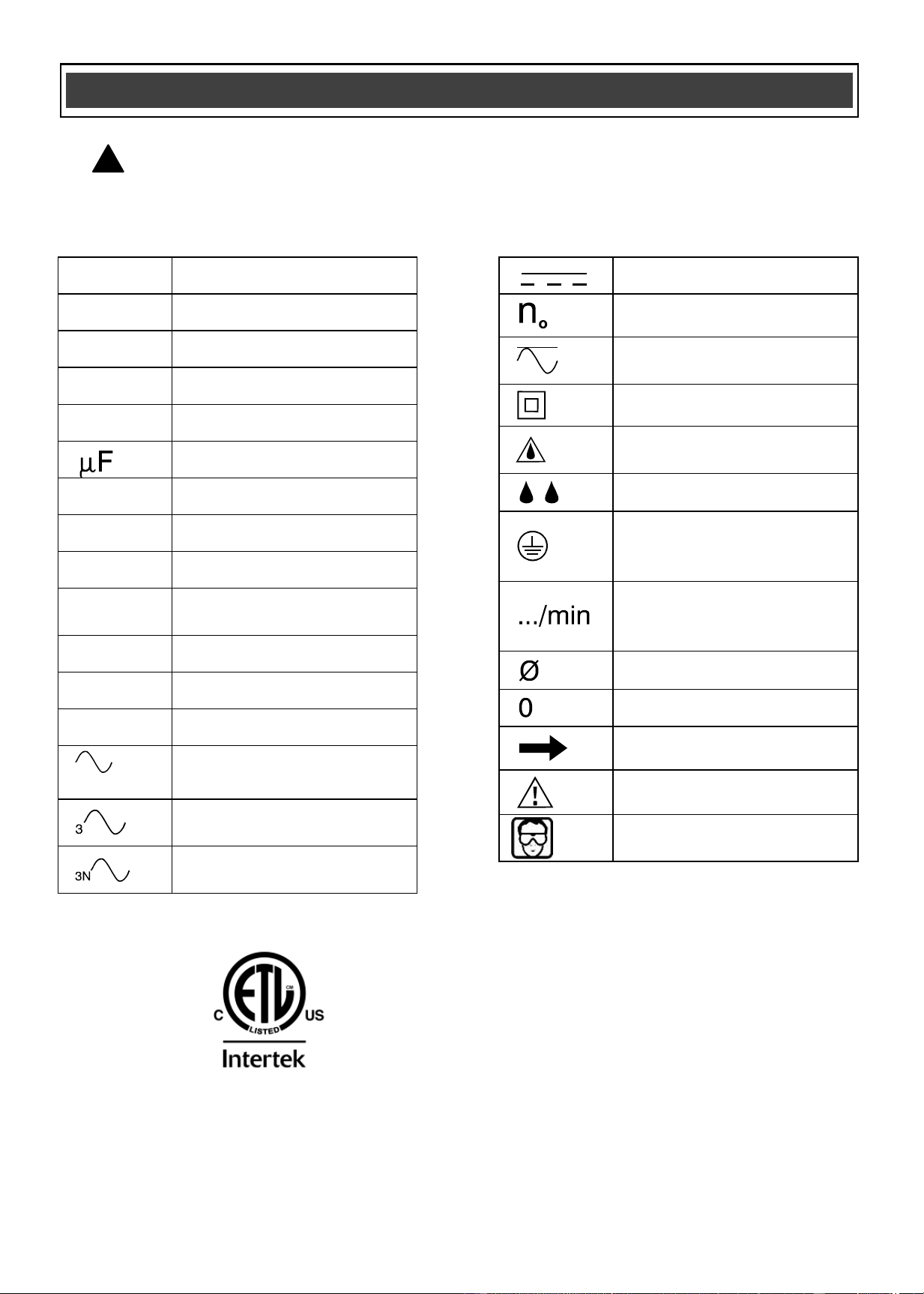
V
Volts
A
Amperes
Hz
Hertz
W
Watts
kW
Kilowatts
Microfarads
L
Litres
kg
Kilograms
H
Hours
N/cm
2
Newtons per square
centimetre
Pa
Pascals
Min
Minutes
S
Seconds
or a.c.
Alternating current
Three-phase alternating
current
Three-phase alternating
current with neutral
Direct current
No load speed
Alternating or direct
current
Class II construction
Splash-proof
construction
Watertight construction
Protective grounding at
grounding terminal,
Class I tools
Revolutions or
reciprocations per
minute
Diameter
Off position
Arrow
Warning symbol
Wear your safety
glasses
SYMBOLS
WARNING: Some of the following symbols may appear on the cordless
drill. Study these symbols and learn their meaning. Proper interpretation of
these symbols will allow for more efficient and safer operation of this tool.
!
Downloaded from www.ManualsFile.com manuals search engine
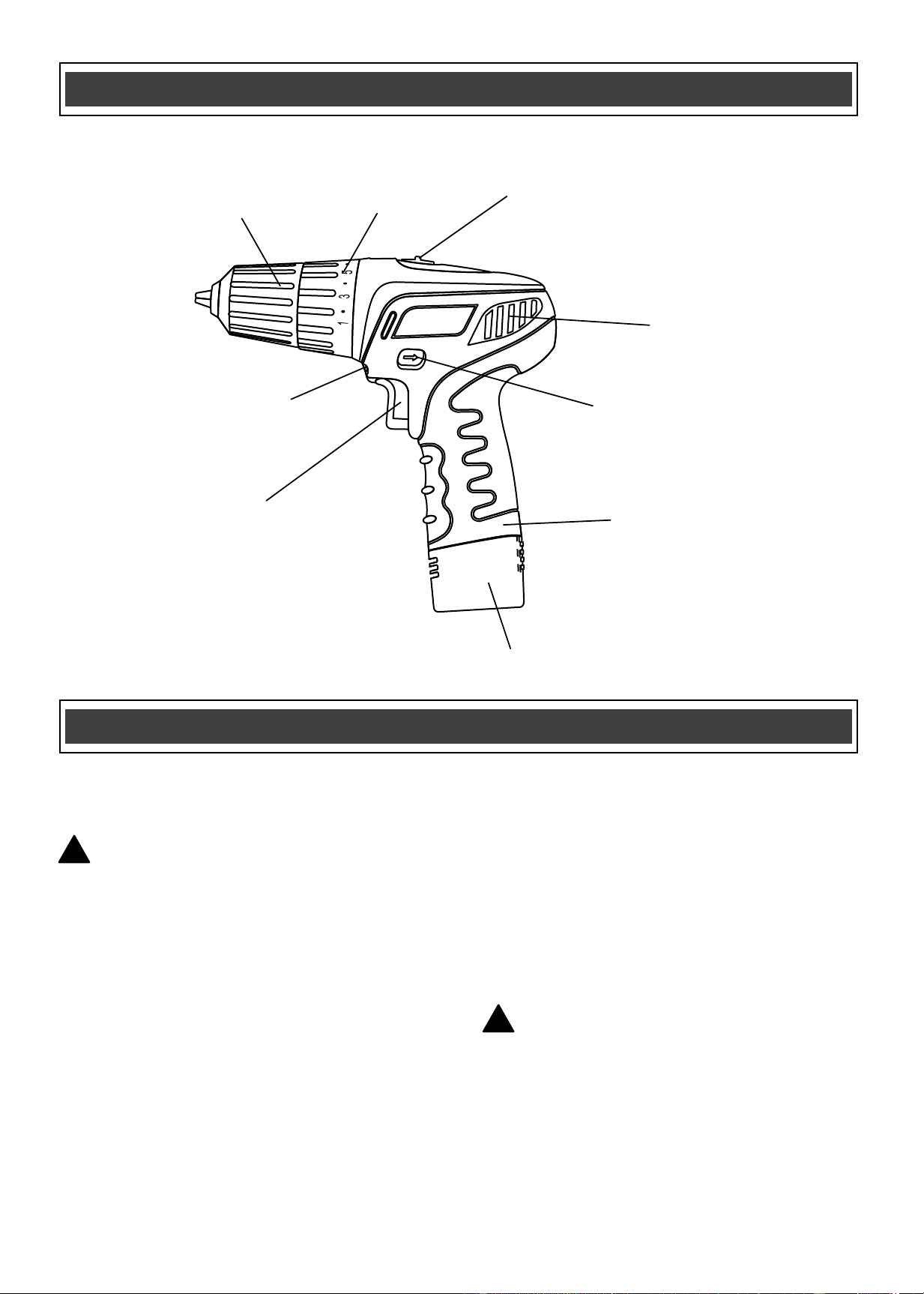
12
Chuck
Variable speed
trigger switch
Forward/reverse
button
Torque
clutch
Air vents
Battery
cavity
LED light
Speed selection
switch
Battery
AVAILABLE ACCESSORIES
WARNING: Use only accessories
that are recommended for this cordless
drill. Follow the instructions that
accompany the accessories. The use of
improper accessories may result in
injury to the operator or damage to the
cordless drill.
Before using any accessory, carefully read
the instructions or the owner’s manual for
the accessory.
Replacement 12V battery 252-0512
Replacement 12V charger 252-0510
Drill bits
Screwdriver bits
Nut drivers
WARNING: If any part is missing or
damaged, do not plug charger into the
power source or install the battery in the
tool until the missing or damaged part is
replaced.
KNOW YOUR CORDLESS DRILL
ACCESSORIES
!
!
Downloaded from www.ManualsFile.com manuals search engine
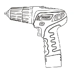
13
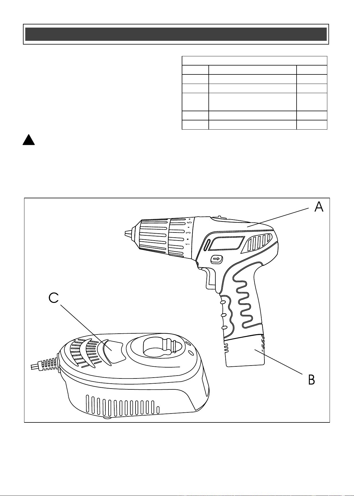
CONTENTS
Carefully unpack the cordless drill.
Compare the contents against the
“CORDLESS DRILL COMPONENTS”
chart at right.
NOTE: See illustration of cordless drill
below.
WARNING: To avoid fire or toxic
reaction, never use gasoline, naphtha,
acetone, lacquer thinner or similar
highly volatile solvents to clean the
tool.
!
CONTENTS
CORDLESS DRILL COMPONENTS
KEY
DESCRIPTION
QTY
A
Cordless drill
1
B
12V Li-ion battery
1
C
30–40 min. LED
diagnostic charger
1
Tote (not illustrated)
1
Owner’s Manual
1
Downloaded from www.ManualsFile.com manuals search engine
14
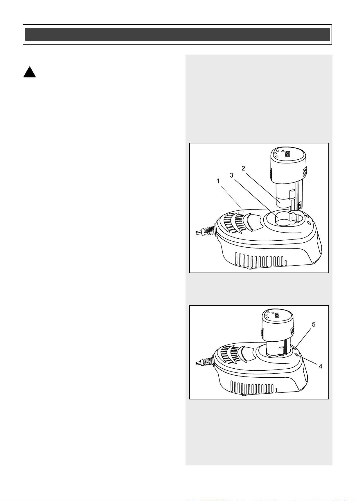
CHARGING THE BATTERY PACK
WARNING: Use only the
diagnostic charger supplied with the
tool to charge the 12 V Li-ion battery
supplied with the tool. Charging any
other batteries with this charger may
damage the charger, and possibly
cause serious injury.
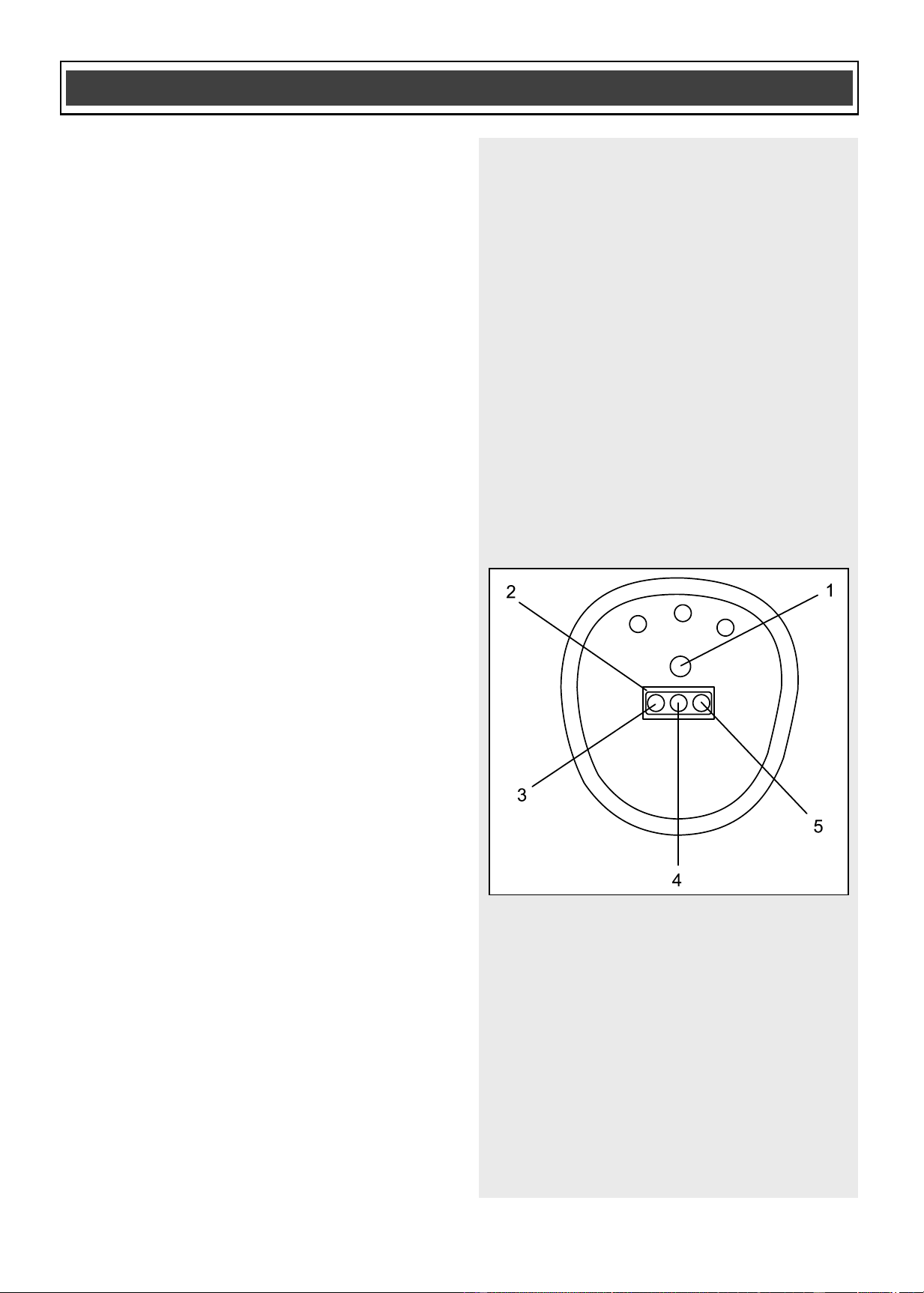
1. To charge the battery, place the
charger (1) in a dry location near a
120 V AC, 60 Hz electrical outlet
(Fig. 1).
2. Place the battery stem (2) into the
matching cavity (3) in the top of the
charger.
NOTE: Make sure the battery is pressed
fully onto the charger as far as it will go.
3. Plug the battery charger into the
120 V AC, 60 Hz wall receptacle.
NOTE: Do NOT charge batteries when the
work area or the battery temperature is at
or below 0°C (32° F) or above
45°C (113° F).
When the battery charger is plugged into a
“live” receptacle, the battery charger will
begin charging the battery. The red LED
(4) and the green LED (5) on the top of the
charger will indicate the charging status
(Fig. 2).
ASSEMBLY AND OPERATING
!
Fig. 1
Fig. 2
Downloaded from www.ManualsFile.com manuals search engine
15
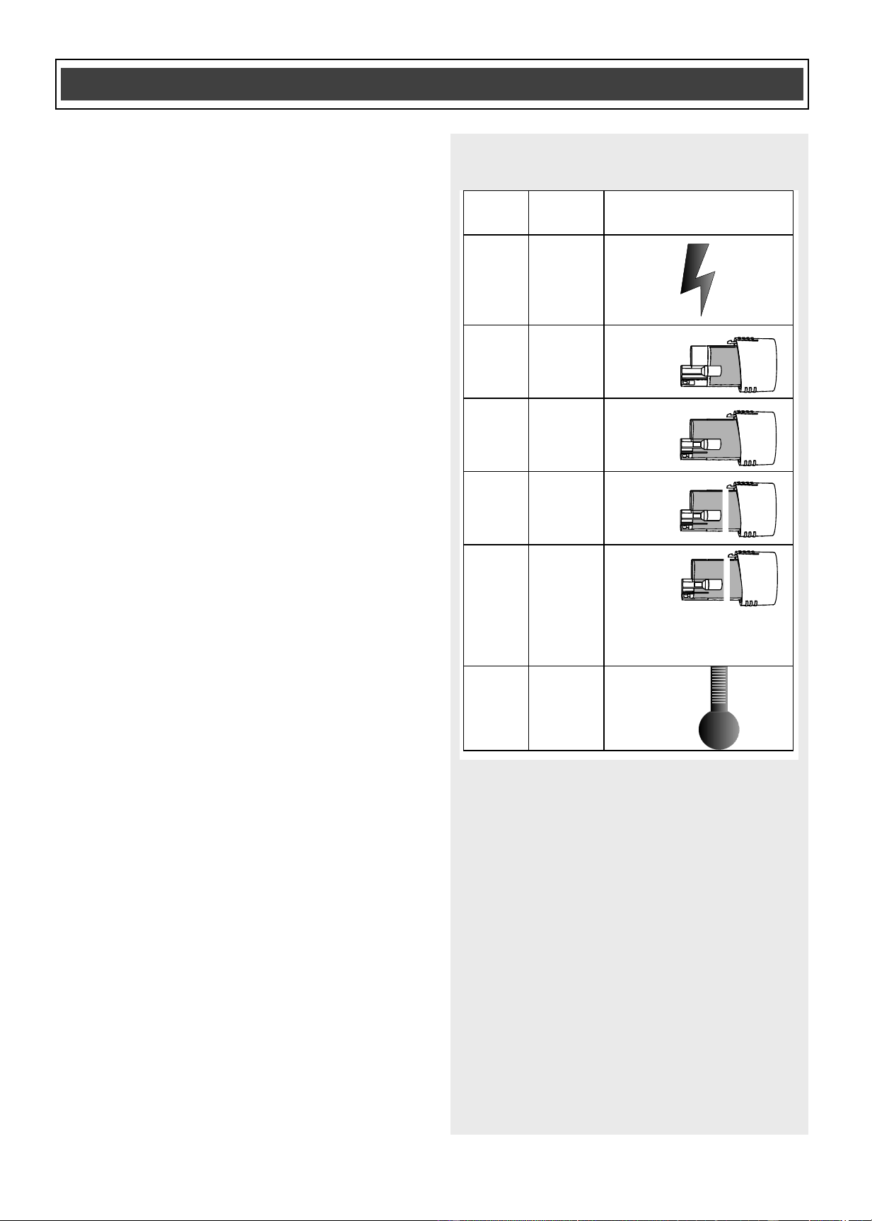
CHARGER LED FUNCTIONS (Fig. 3)
Power ON
The green LED will stay ON when the
charger is plugged into a ”live” power
source.
Battery partially charged
The red LED will flash during charging.
Battery fully charged
When the battery is approximately 100%
charged, the red LED will turn OFF and the
green LED will blink for a short period of
time. The blinking green LED indicates the
charger is in trickle charge mode while
completing the charging cycle.
Under normal circumstances, the battery
will be fully charged in approximately
50 minutes.
NOTE: You may use the battery as soon
as the green LED begins to flash, as the
battery will be at least 98% charged.
Defective battery
The red LED will stay ON when a defective
battery is detected and it should be
replaced. Both the red and green LED’s
will stay ON when a defective battery is
detected and the battery is within the
normal charging temperature range.
NOTE: For additional help, call the
customer support toll free number
1-866-349-8665.
Too hot or too cold
Both the red LED and the green LED will
stay ON when the work area or battery
temperature is either too high or too low.
Remove the battery from the charger and
let it sit at room temperature 21° C (70° F)
for about one hour, and resume charging.
ASSEMBLY AND OPERATING
Red
light
Green
light
Function
—
On
---
---
—
—
—
—
—
Battery
charging
Trickle
charging
Defective
battery
Too hot or
too cold
Flashing
Flashing
On
On
On
Defective
Battery
(when battery is within
normal charging
temperature range)
On
On
Fig. 3
Downloaded from www.ManualsFile.com manuals search engine
16
CHECKING THE BATTERY CHARGE
STATUS (if your battery is equipped with
the charge indicator system)
The level of charge remaining in the
battery can be checked by using the
battery charge indicator system that is
contained in the end of the battery.
NOTE: The battery charge remaining may
be checked while the battery is installed in
the tool with the ON/OFF switch turned
OFF. It may also be checked while the
battery is removed from the tool. DO NOT
check the battery charge remaining while
the battery is in the charger. You will get a
false reading and you may also damage
the battery status system.
1. Press and hold the battery status
button (1) located in the end of the
battery (Fig. 4).
2. One or more of the three LED lights in
the LED window (2) will come ON to
indicate the amount of charge that is
remaining in the battery as follows:
Red + Amber + Green (3, 4 & 5) – 2/3 to
full capacity
Red + Amber (3 & 4) – 1/3 to 2/3 capacity
Red (3) – less than 1/3 capacity
3. Release the battery status button to
turn the LED’s OFF.
ASSEMBLY AND OPERATING
Fig. 4
Downloaded from www.ManualsFile.com manuals search engine
17
INSTALLING A BATTERY IN THE DRILL
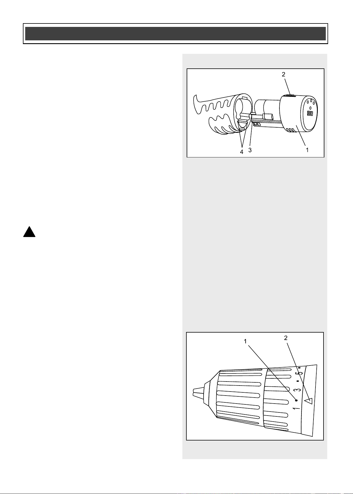
1. Remove the discharged battery (1)
from the tool by pressing on the
battery release button (2) on the top of
the battery (Fig. 5).
2. Pull the battery out of the tool handle.
3. Slide the fully charged battery into the
matching cavity in the tool handle
where the discharged battery has
been removed.
NOTE: Make sure the two keys (3) in the
battery stem align with the matching key
ways (4) in the handle. The battery release
button will “click” into place when the
battery is fully installed.
WARNING: Do not immerse the
battery pack in water. Sudden cooling
could cause the hot battery to explode or
leak.
ADJUSTING THE TORQUE
Your drill is equipped with an adjustable
torque clutch for driving different types of
screws into different types of materials. It
also has a setting for “drilling”. The proper
setting depends upon the type of material
and size of screw being used and the
function required.
Adjust the torque setting as follows:
1. Identify the torque settings located on
the torque adjustment ring (1) (Fig. 6).
2. Rotate adjustment ring to align the
correct torque setting number with the
torque indicator arrow (2). See the
chart on the following page for correct
torque settings.
ASSEMBLY AND OPERATING
!
Fig. 5
Fig. 6
Downloaded from www.ManualsFile.com manuals search engine
18
ADJUSTING THE TORQUE – cont’d
1–4 For driving small screws
5–7 For driving medium sized screws
into soft materials
8–10 For driving screws into soft &
medium-density materials
9–13For driving screws into hardwood
14–16 For driving large screws
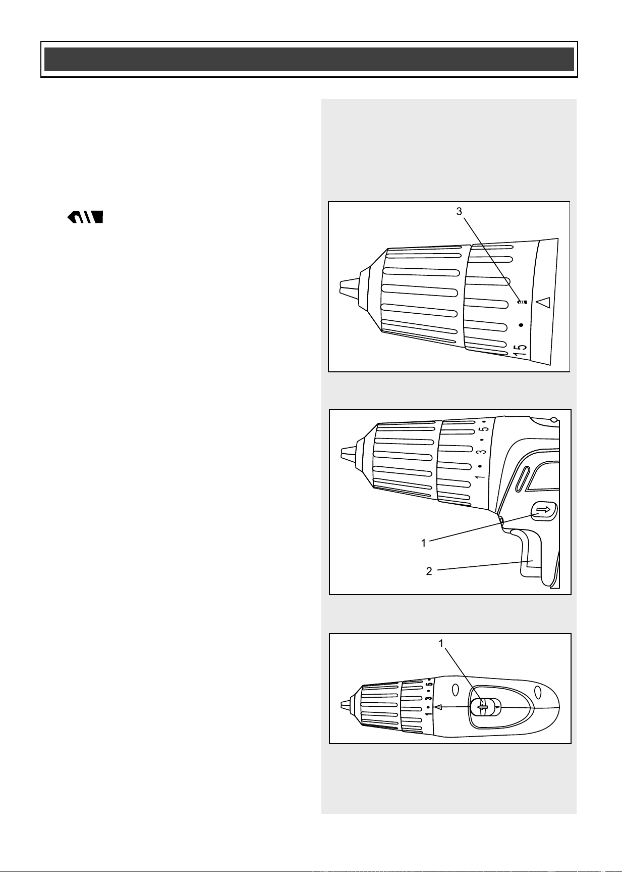
For drilling. This position is
marked with a drill bit icon (3) on the
torque adjustment ring (Fig. 7).
FORWARD/REVERSE SWITCH
The forward/reverse switch (1) is
conveniently mounted above the trigger
switch (2) (Fig. 8). To make the drill rotate
clockwise for drilling or driving screws,
push the forward/reverse switch to the left.
To make the drill rotate counter-clockwise
for removing screws, push the
forward/reverse switch to the right.
NOTES:
a) Never change the position of the
forward/reverse switch while chuck is
turning.
b) The trigger switch will NOT function with
the forward/reverse switch in the middle
position.
TWO-SPEED GEAR BOX SWITCH
Set the speed-control switch (1) to the
desired speed (Fig. 9). Slide the speed-
control switch FORWARD for low-speed
operation. Slide the speed control-switch
BACK for high-speed operation.
NOTES:
a) Use low-speed setting for drilling large
holes and for driving screws.
b) Use high-speed setting for drilling
smaller holes.
c) Do NOT change the speed-control
switch position while drill is turned ON.
Damage to the gears may result.
ASSEMBLY AND OPERATING
Fig. 7
Fig. 8
Fig. 9
Downloaded from www.ManualsFile.com manuals search engine
19
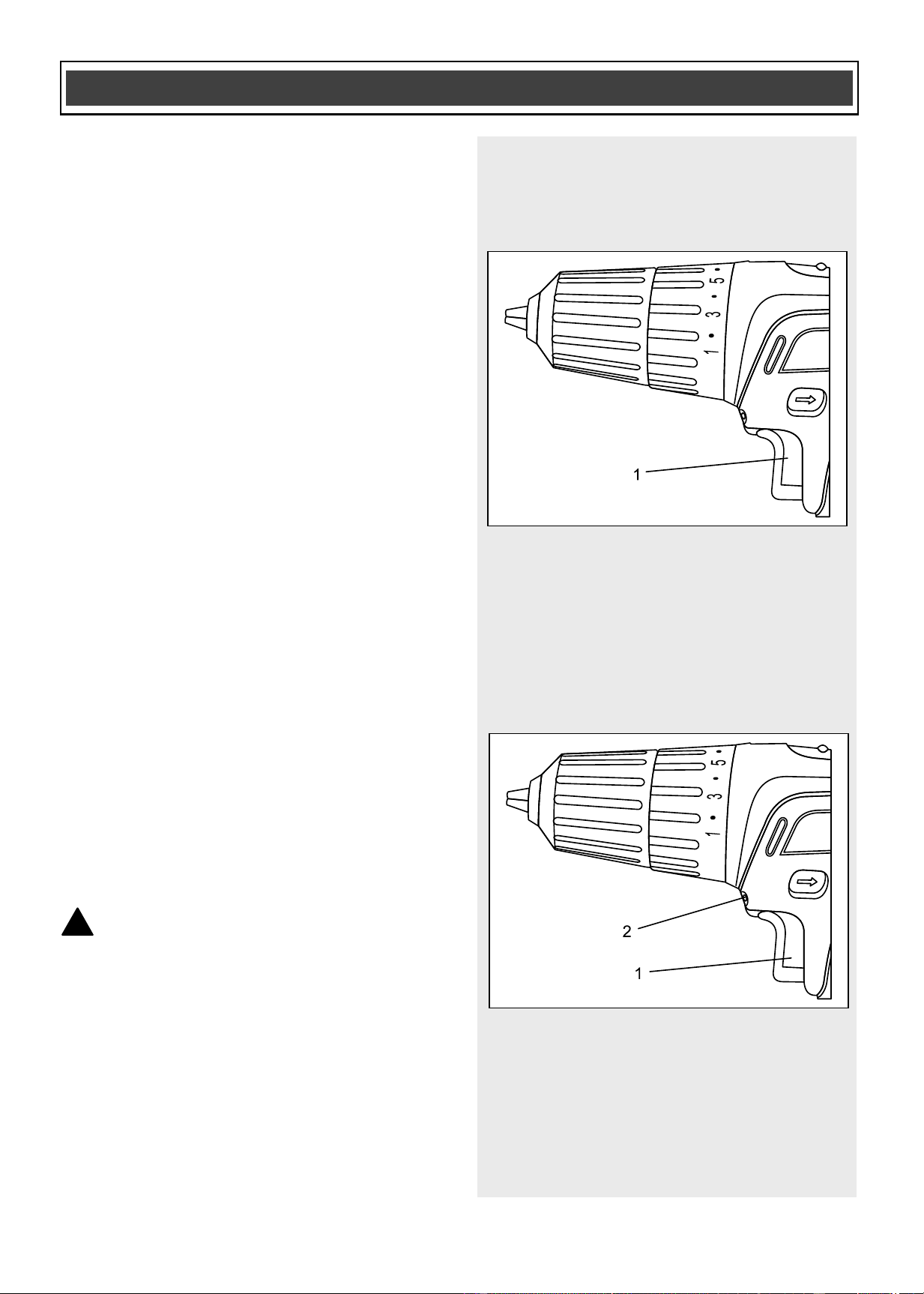
VARIABLE-SPEED TRIGGER SWITCH
This drill is equipped with a variable-speed
ON/OFF trigger switch.
1. To start drill, gently squeeze the
trigger switch (1) (Fig. 10).
NOTE: The drill will turn at its slowest
speed when the trigger switch is
depressed slightly. The drill will turn at its
fastest speed when the trigger switch is
fully depressed.
2. To stop the drill, release the trigger
switch.
NOTE: Drilling at a slow speed for an
extended period of time may cause the drill
motor or the battery pack to overheat. If
either the drill or the battery get hot, stop
drilling and allow them to cool for at least
15 minutes.
LED WORK LIGHT
The LED work light (2) will automatically
turn ON when the trigger switch (1) is
squeezed (Fig. 11). It will automatically
turn OFF when the trigger switch is
released.
INSTALLING DRILL BITS
WARNING: Never hold the chuck
body with one hand and use the drill
power to rotate the drill body to loosen
or tighten bits. Serious injury may
result.
This drill is equipped with a keyless chuck.
This chuck is designed to provide easy
one-handed tightening and loosening of
the chuck jaws.
ASSEMBLY AND OPERATING
!
Fig. 10
Fig. 11
Downloaded from www.ManualsFile.com manuals search engine
20
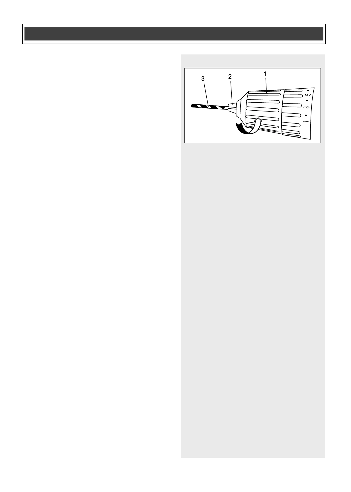
INSTALLING DRILL BITS – cont’d
1. To open the keyless drill chuck, grasp
and hold the chuck body (1) and
rotate it in a counter-clockwise
direction until the chuck jaws (2) open
wide enough to accept the bit (3)
(Fig. 12).
NOTE: The drill spindle will automatically
lock when the drill is stopped.
2. Insert the bit into the chuck the full
length of the jaws. Raise the front of
your drill slightly to prevent the bit from
falling out of the chuck jaws.
3. Tighten the chuck jaws onto the bit by
turning the chuck body in a clockwise
direction.
NOTE: Make sure the bit is properly
aligned in the jaws and NOT at an angle.
An improperly aligned bit could be thrown
from the chuck when the drill is started.
Make sure the chuck jaws grasp the flat
sides of a screwdriver bit.
4. Finish tightening the chuck jaws.
Firmly grasp the chuck body with your
hand and rotate it in a clockwise
direction.
NOTES:
a) The automatic spindle lock will prevent
the spindle from rotating while the chuck
body is being tightened.
b) Continue to rotate the chuck body until
the clicking stops and you can no longer
turn it any further BY HAND.
c) Hand-tighten the chuck body. Do NOT
use pliers. You will damage the chuck.
ASSEMBLY AND OPERATING
Fig. 12
Downloaded from www.ManualsFile.com manuals search engine

21
INSTALLING DRILL BITS – cont’d
WARNING: Do not insert drill bit
into chuck and tighten as shown in
Fig. 13. The drill bit MUST be properly
inserted with all three of the chuck jaws
holding the bit centred in the chuck. Failure
to properly insert drill bit could cause the
drill bit to be thrown from the chuck,
resulting in possible serious injury or
damage to the chuck.
REMOVING BITS
1. To open the keyless drill chuck, grasp
and hold the chuck collar and rotate it
in a counter-clockwise direction until
the chuck jaws open and release the
bit.
2. Remove the bit.
!
ASSEMBLY AND OPERATING
Fig. 13
Downloaded from www.ManualsFile.com manuals search engine
22
DRILLING
When drilling into smooth, hard surfaces
such as metal, use a centre punch to mark
the desired hole location. This will prevent
the drill bit from slipping off centre as the
hole is started.
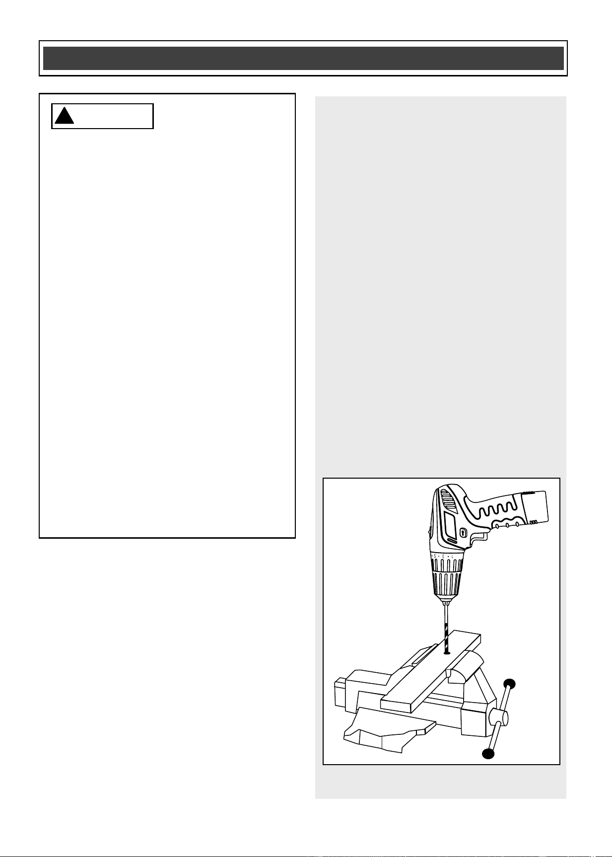
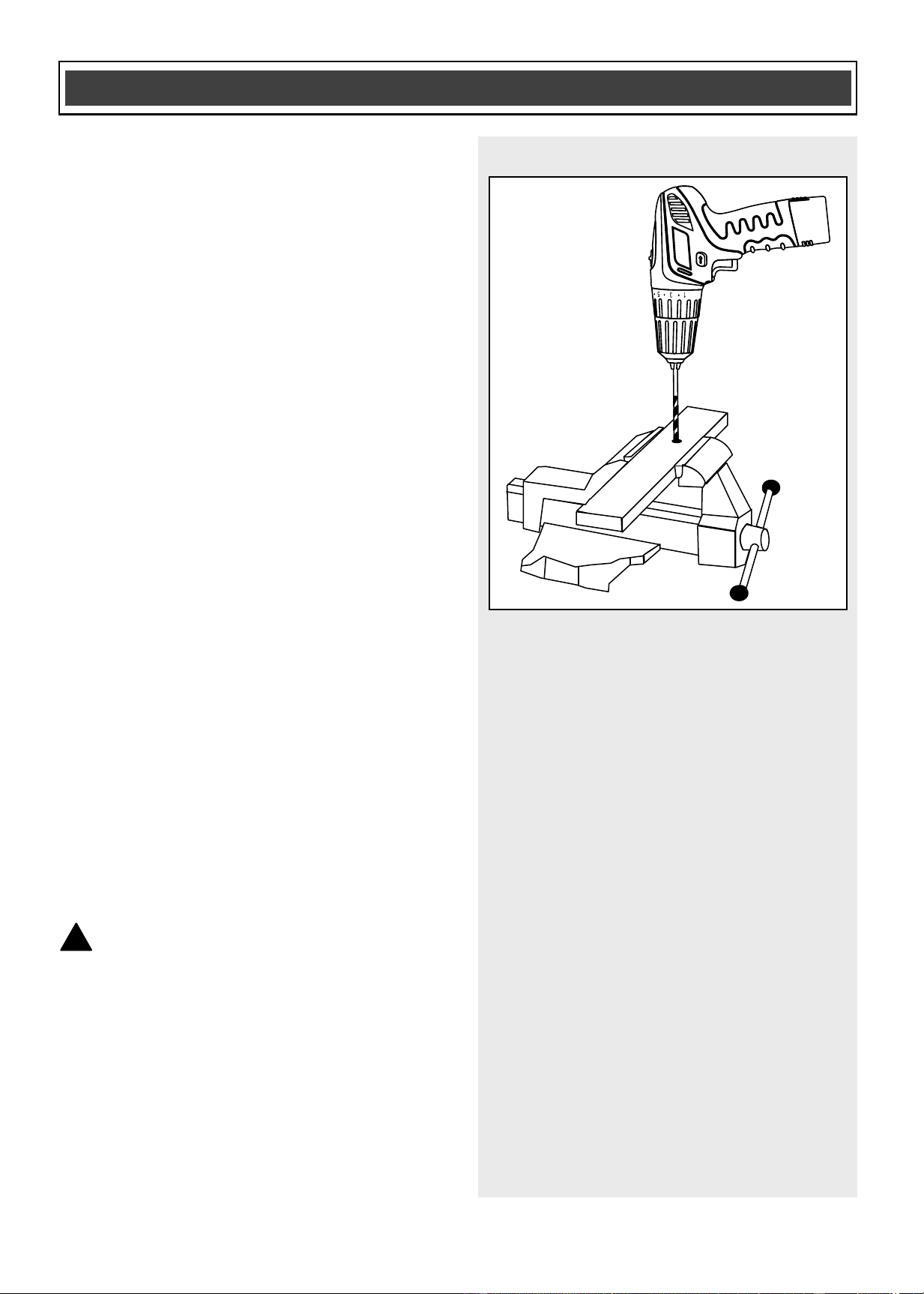
The workpiece to be drilled should be
secured in a vice or with clamps to keep it
from turning as the drill bit rotates
(Fig. 14).
ASSEMBLY AND OPERATING
For safety reasons, the operator
must read the sections of this
Owner’s Manual entitled “GENERAL
SAFETY WARNINGS”, “POWER
TOOL SAFETY”, “SPECIFIC SAFETY
RULES”, “BATTERY & CHARGER
SAFETY” and “SYMBOLS” before
using this cordless drill.
Verify the following every time the
drill is used:
1. Safety glasses, safety goggles,
or face shield is being worn.
2. Hearing protection and dust
mask are being worn when
drilling in concrete.
3. The chuck has not worked loose
on the spindle.
4. The bit is in good condition, and
is properly tightened into the
chuck.
Failure to observe these safety rules
will significantly increase the risk of
injury.
WARNING
!
Fig. 14
Downloaded from www.ManualsFile.com manuals search engine
23
DRILLING – cont’d
1. Check the drill bit to make sure it is
firmly locked into the drill chuck, and
verify that the forward/reverse switch
is in the forward position.
2. Set torque clutch to the drilling
position.
3. Hold the drill firmly with both hands
whenever possible. Use one hand to
grasp the handle and switch.
NOTE: Make sure the hand placed on the
body of the drill does not cover the air
vents. Covering these air vents will reduce
motor cooling, and possibly lead to
overheating the motor.
4. While holding the drill firmly, place the
point of the drill bit at the point to be
drilled. Squeeze the switch trigger to
start the drill.
NOTES: Always use a higher drill speed
when drilling small holes. Use a slower drill
speed when drilling large holes.
5. Move the drill bit into the workpiece
applying only enough pressure to
keep the bit cutting. Do not force the
drill bit or apply sideways pressure to
elongate the hole.
WARNING: Be prepared for
binding and bit breakthrough. When
these situations occur, the drill bit has a
tendency to grab the workpiece. This
action will kick the drill opposite to the
direction of drill bit rotation, and could
cause loss of control when breaking
through material as you complete
drilling the hole. If you are not prepared,
this loss of control can result in serious
injury.
!
ASSEMBLY AND OPERATING
Fig. 14
Downloaded from www.ManualsFile.com manuals search engine

24
DRILLING – cont’d
When drilling metals, use a light oil on the
drill bit to keep it from overheating. The oil
will prolong the life of the drill bit and
improve the cutting action. If the bit jams in
the workpiece, or if the drill stalls, release
the trigger switch immediately. Remove the
bit from the workpiece and determine the
reason for jamming.
DRIVING SCREWS
When driving screws, care must be taken
to use the bit that correctly fits the screw
being driven. Make sure you use the
largest bit size that will properly fit into the
head of the screw.
1. Select the correct screwdriver bit for
the screw being driven.
2. Fasten the screwdriver bit into the
chuck, making sure the flat sides of
the bit are gripped by the chuck jaws.
3. Set the torque clutch to the
appropriate setting, based on the
chart on Pages 17 & 18.
NOTE: If material is particularly soft or
porous, set the torque clutch to a lower
setting to avoid overdriving the screw.
4. If the screw is driven too far into the
workpiece before the clutch releases,
set the clutch to a lower setting, and
do not pull the trigger switch fully
back. If the screw is not driven far
enough into the workpiece, set the
clutch to a higher setting.
NOTE: Do not continue to drive the screw
once the clutch has released. This causes
unnecessary wear of the clutch.
ASSEMBLY AND OPERATING
Downloaded from www.ManualsFile.com manuals search engine
25
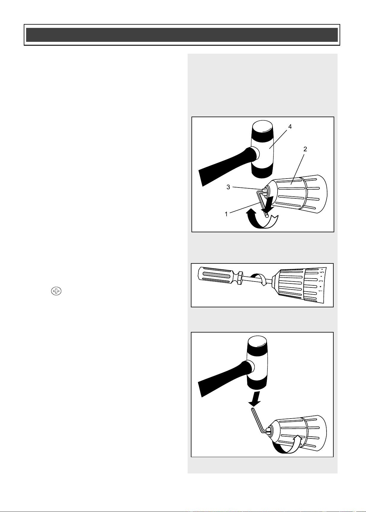
REMOVING THE CHUCK
To remove the chuck:
1. Remove the battery pack from the
drill.
2. Insert a 5/16” (8 mm) or larger hex key
(1) into the chuck (2) and tighten the
chuck jaws securely (Fig. 15). Make
sure each of the chuck jaws (3) is
seated on the flat surfaces of the hex
key.
3. Tap the hex key sharply with a mallet
(4) in a clockwise direction. This action
will loosen the screw in the chuck for
easy removal.
4. Open chuck jaws and remove the hex
key.
5. Open the chuck jaws as far as
possible.
6. Remove the chuck screw using a
#2 screwdriver (Fig. 16).
NOTE: Turn the screw CLOCKWISE to
remove it. This screw has a left-handed
thread.
7. Insert the hex key into the chuck and
tighten jaws of chuck securely
(Fig. 17). Tap the hex key sharply with
a mallet in a COUNTER-CLOCKWISE
direction. This will loosen the chuck on
the spindle. The chuck can now be
unscrewed and removed from the
spindle by hand.
ASSEMBLY AND OPERATING
Fig. 15
Fig. 16
Fig. 17
Downloaded from www.ManualsFile.com manuals search engine
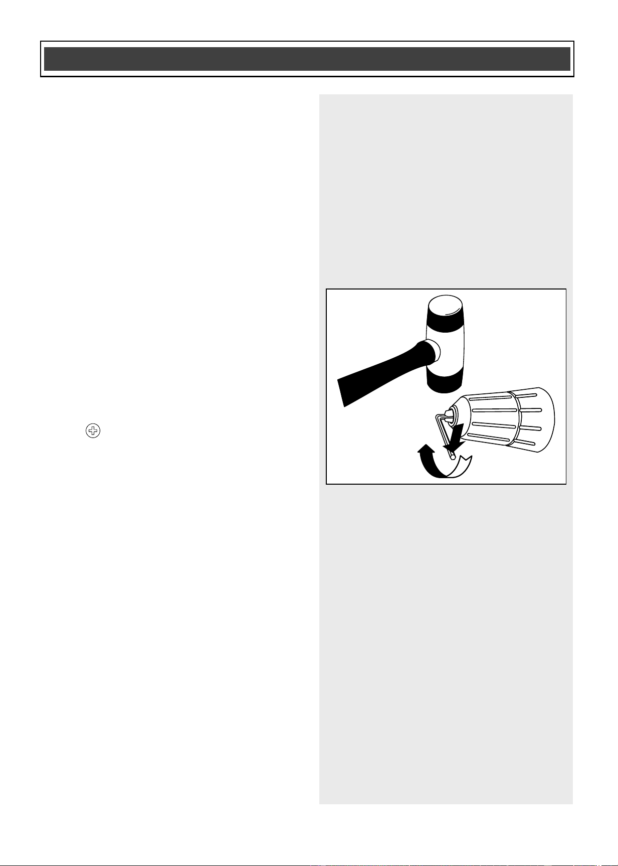
26
RETIGHTENING A LOOSE CHUCK
After installing a chuck that has previously
been removed, the chuck may become
loose on the spindle and develop a
wobble. Also, the chuck screw may
become loose, causing the chuck jaws to
bind and preventing them from closing. To
tighten the chuck, follow these steps:
1. Insert the hex key into the chuck and
tighten the chuck securely.
2. Tap the hex key sharply with a mallet
in a CLOCKWISE direction (Fig. 18).
This will tighten the chuck on the
spindle.
3. Open the chuck jaws and remove the
hex key.
4. Tighten the chuck screw using a
#2 screwdriver.
NOTE: Turn screw COUNTER-
CLOCKWISE to tighten it. This screw has
a left-handed thread.
ASSEMBLY AND OPERATING
Fig. 18
Downloaded from www.ManualsFile.com manuals search engine

27
GENERAL
WARNING: When servicing, use
only identical replacement parts. The
use of any other part may create a
hazard or cause product damage.
DO NOT use solvents when cleaning
plastic parts. Plastics are susceptible to
damage from various types of commercial
solvents and may be damaged by their
use. Use a clean cloth to remove dirt, dust,
oil, grease etc.
WARNING: Do not allow brake
fluids, gasoline, petroleum-based
products, penetrating oils, etc. to come
into contact with plastic parts. They
contain chemicals that can damage,
weaken or destroy plastic.
DO NOT abuse power tools. Abusive
practices can damage the tool and the
workpiece.
WARNING: DO NOT attempt to
modify tools or create accessories. Any
such alteration or modification is
misuse and could result in a hazardous
condition leading to possible serious
injury. It will also void the warranty.
LUBRICATION
All of the bearings in this tool are
lubricated with a sufficient amount of high-
grade lubricant for the life of the unit under
normal conditions. Therefore, no further
lubrication is required.
!
!
!
MAINTENANCE
Downloaded from www.ManualsFile.com manuals search engine
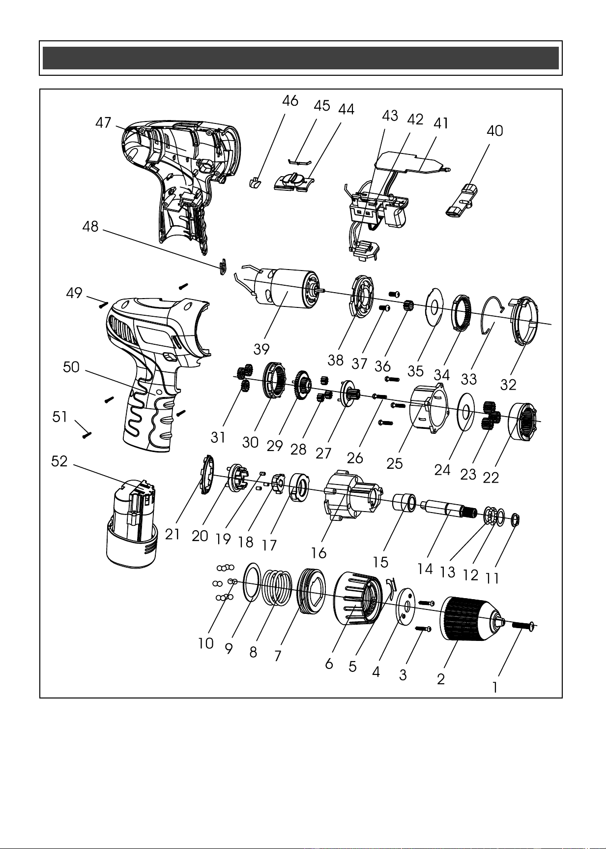

29
WARNING: When servicing, use only original equipment replacement parts. The
use of any other parts may create a safety hazard or cause damage to the cordless drill.
Any attempt to repair or replace electrical parts on this cordless drill may create a safety
hazard unless repairs are performed by a qualified technician. For more information, call
the Toll-free Helpline, at 1-866-349-8665.
Always order by PART NUMBER, not by key number.
Key #
Part #
Part Name
Quantity
1
4020030001
Chuck screw
1
2
1140030015
Chuck
1
3
1140030015
Tapping screw
2
4
4030010034
Compressing plate
1
5
205007000
Positioning spring
1
6
3120080016
Torque setting ring
1
7
3120080016
Inner threaded ring
1
8
2050060050
Spring
1
9
2050060050
Washer
1
10
2030020009
Ball group
18
11
4080060001
Fixing ring
1
12
4100020008
Washer
2
13
2030020010
Small ball group
15
14
4080020002
Shaft
1
15
2040050048
Shaft bushing
1
16
2010080040
Gear box
1
17
3150070003
Shaft locking ring
1
18
2010240001
Driving block
1
19
2010230001
Needle roller
6
20
4110020019
Planetary carrier
1
PARTS LIST
!
Downloaded from www.ManualsFile.com manuals search engine

30
Key #
Part #
Part Name
Quantity
21
2010240003
Limit position ring
1
22
2010090007
Gearing ring
1
23
2010010009
Planetary gear
3
24
2030020007
Washer
1
25
3150080002
H/L speed gear box
1
26
4030010029
Tapping screw
4
27
4030010029
Planetary carrier
1
28
2010010008
Planetary gear
3
29
1170070006
Planetary carrier
1
30
1170070006
Moveable ring gear
1
31
2010010012
Planetary gear
3
32
2010010012
Timing point ring
1
33
2050080037
2-speed lever
1
34
2010090010
Fixed ring gear
1
35
2010090010
Washer
1
36
2030020006
Motor gear
1
37
2010180003
Screw
2
38
4020010028
Motor flange
1
39
3150090003
Motor assembly
1
40
3120030024
FWD/REV lever
1
41
3120030024
PCB
1
42
1130050007
Switch assembly
1
43
1060190001
Contact plate
1
44
3120120102
Speed selector button
1
45
2050070002
Lever
1
46
2050070002
LED lens
1
47
3160060024
Left housing
1
48
2030030083
Clip
1
49
4030010031
Tapping screw
5
50
3010010147
Right housing
1
51
4030010012
Tapping screw
2
52
1070060003
Battery pack
1
PARTS LIST
Downloaded from www.ManualsFile.com manuals search engine

31
Rev 1.9 17/06/2011
PERFORMAX
®
12 V CORDLESS DRILL WARRANTY
30-DAY MONEY BACK GUARANTEE:
This PERFORMAX
®
brand power tool carries our 30-Day Money Back
Guarantee. If you are not completely satisfied with your PERFORMAX
®
brand
power tool for any reason within thirty (30) days from the date of purchase, return
the tool with your original receipt to any MENARDS® retail store, and we will
provide you a refund – no questions asked.
2-YEAR LIMITED WARRANTY:
This PERFORMAX
®
brand power tool carries a 2-Year Limited Warranty to the
original purchaser. If, during normal use, this PERFORMAX
®
power tool breaks
or fails due to a defect in material or workmanship within two (2) years from the
date of original purchase, simply bring this tool with the original sales receipt
back to your nearest MENARDS® retail store. At its discretion, PERFORMAX
®
agrees to have the tool or any defective part(s) repaired or replaced with the
same or similar PERFORMAX
®
product or part free of charge, within the stated
warranty period, when returned by the original purchaser with original sales
receipt. Not withstanding the foregoing, this limited warranty does not cover any
damage that has resulted from abuse or misuse of the Merchandise. This
warranty: (1) excludes expendable parts including but not limited to blades,
brushes, belts, bits, light bulbs, and/or batteries; (2) shall be void if this tool is
used for commercial and/or rental purposes; and (3) does not cover any losses,
injuries to persons/property or costs. This warranty does give you specific legal
rights and you may have other rights, which vary from state to state. Be careful,
tools are dangerous if improperly used or maintained. Seller’s employees are
not qualified to advise you on the use of this Merchandise. Any oral
representation(s) made will not be binding on seller or its employees. The rights
under this limited warranty are to the original purchaser of the Merchandise and
may not be transferred to any subsequent owner. This limited warranty is in lieu
of all warranties, expressed or implied including warranties or merchantability
and fitness for a particular purpose. Seller shall not be liable for any special,
incidental, or consequential damages. The sole exclusive remedy against the
seller will be for the replacement of any defects as provided herein, as long as
the seller is willing or able to replace this product or is willing to refund the
purchase price as provided above. For insurance purposes, seller is not allowed
to demonstrate any of these power tools for you.
For questions / comments, technical assistance or repair parts –
Please Call Toll Free at: 1-866-349-8665 (M-F 8am – 6pm)
SAVE YOUR RECEIPTS. THIS WARRANTY IS VOID WITHOUT THEM.
Distributed by: Menard, Inc., Eau Claire, WI 54703
Downloaded from www.ManualsFile.com manuals search engine