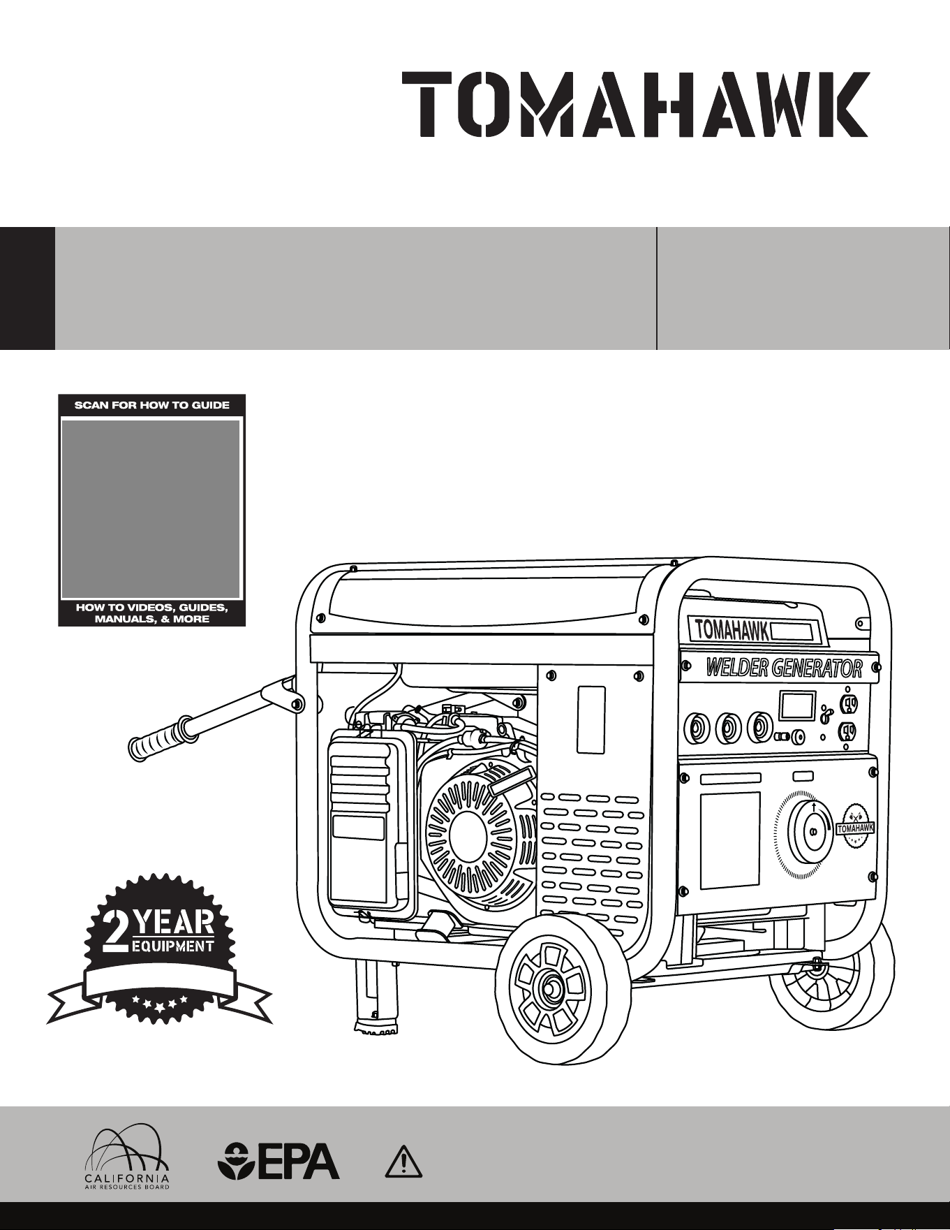
Operation Manual
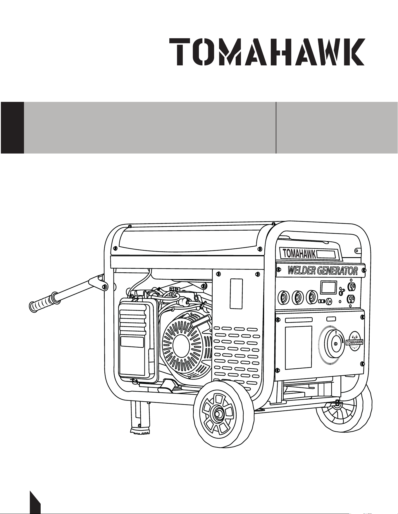
WELDER GENERATOR
MODEL NUMBER: TWG210A
To reduce the risk of injury, the user must read and understand the Operator’s
Manual before using this product. Save these instructions for future reference.
W
A
R
R
A
N
T
Y
TWG120A
WELDER GENERATOR
TWG210A

2
TABLE OF CONTENTS
1. SAFETY INFORMATION
1.1 Operating Safety
1.2 Arc Welding Safety
1.3 Service Safety
2. TECHNICAL PERFORMANCE
3. SPECIFICATIONS
3.1 Welding Generator Parts
3.2 Unpacking the Unit
4. ASSEMBLY
4.1 Wheel and Handle Kit Assembly
4.2 Cable Assembly
5. OPERATION
5.1 Oil and Fueling
5.2 Starting instructions
5.3 Recommended Battery Information
5.4 Welder Generator Panel Display
6. SELECTING CABLE SIZES
6.1 Weld Cable Size and Total Cable
7. ELECTRODE SELECTION CHART
8. TIG TORCHES
8.1 Technical Specifications
8.2 Torch Diagram
9. KNOW YOUR CROSS VALVE (+)
10. TIG TORCH INSTALLATION
11. STORAGE
11.1 Clean and Inspect
11.2 Prepare the Fuel System
11.3 Lubricate and Store Correctly
12. WELDING 101
12.1 Stick Welding Guideline
13. TYPES OF GROOVE JOINTS
13.1 Single Groove Welds
13.2 Double Groove Welds
14. WELDING TEE JOINTS
14.1 Steps to Weld Tee Joints
14.2 Types of Welds for Tee Joints
15. WELD TEST
15.1 Destructive Testing
15.2 Non-Destructive Testing
16. REPLACEMENT PARTS
17. TROUBLESHOOTING
18. MAINTENANCE RECORD
19. EQUIPMENT WARRANTY
20. SERVICE CENTERS
21. PARTS MANUAL
4
5
6
9
10
11
12
12
13
13
14
14
14
14
15
16
17
17
17
18
18
19
20
21
22
22
22
22
22
22
23
23
24
24
24
25
25
25
25
26
27
29
29
29
30
3
Register Your Equipment
Thank you for purchasing TOMAHAWK equipment! Your product is covered by the
TOMAHAWK Warranty policy, but in order to activate your warranty, we need you to register
your product. In addition to activating your equipment warranty, product registration will
grant you access to important product updates, streamlined customer service and more.
INCLUDED WITH YOUR REGISTRATION
☑ Equipment Warranty Activation
☑ Product Updates
☑ Streamlined Customer Service
☑ Exclusive Discounts and Sales
STEPS TO REGISTER YOUR EQUIPMENT
1. Visit www.tomahawk-power.com
2. Choose “Product Registration” at the bottom of the page
3. Enter your equipment’s serial number to get started
4. Provide all required information
5. Submit Registration
Equipment Resources
Tomahawk Customer Service doesn’t stop at checkout. We understand to keep a job-site
running smoothly - the proper equipment, spare parts, instruction manuals, and more are
needed at the drop of a hat. Visit www.tomahawk-power.com to gain access to the incredible
resources below.
How To Video Library
More of a visual person? Visit our Video Library for equipment
assembly instructions, troubleshooting tips, and more!
Found on each product listing or the Service Videos Page
Manual and Assembly Guide Library
Visit our Manual Library if you are looking for a lost
operations manual or a particular spare part?
Found on each product listing or the Tomahawk Manuals Page
Service Requests
In need of a quick fix or a service center referral? Submit a
Service Request and a Tomahawk Technician will respond
shortly to get you the help you need.
Choose “Service Request” at the bottom of www.tomahawk-power.com
TWG210A

4
This manual provides information and procedures to safely operate and maintain this
equipment. For your own safety and protection from injury, carefully read, understand, and
observe the safety instructions described in this manual.
Keep this manual or a copy of it with the equipment. If you lose this manual or need an
additional copy, please contact Tomahawk Power, LLC or visit www.tomahawk-power.com
This equipment is built with user safety in mind; however, it can present hazards if
improperly operated or serviced. Follow operating instructions carefully. If you have
questions about operating or servicing this equipment, contact TOMAHAWK®.
The information contained in this manual is based on equipment’s production at the time of
publication. TOMAHAWK® reserves the right to change any portion of this information
without notice.
No part of this publication may be reproduced in any form or by any means,
electronic or mechanical, including photocopying, without express written permission
from TOMAHAWK®.
Any type of reproduction or distribution not authorized by TOMAHAWK® represents an
infringement of valid copyrights and will be prosecuted. We expressly reserve the right to
make technical modifications, even without due notice, which aim at improving our
machines or their safety standards.
1. SAFETY INFORMATION
This manual contains DANGER, WARNING, CAUTION, and NOTE callouts which must be
followed to reduce the possibility of personal injury, damage to the equipment,
or improper service.
This is the safety alert symbol. It is used to alert you to potential personal injury
hazards. Obey all safety messages that follow this symbol to avoid possible injury
or death.
DANGER indicates an imminently hazardous situation which, if not avoided, will
result in death or serious injury.
WARNING indicates a potentially hazardous situation which, if not avoided, could
result in death or serious injury.
CAUTION indicates a potentially hazardous situation which, if not avoided, may
result in minor or moderate injury.
DANGER
WARNING
CAUTION

5
1.1 Operating Safety
Familiarity and proper training are required for the safe operation of equipment!
Equipment operated improperly or by untrained personnel can be dangerous! Read the
operating instructions contained in both this manual and the engine manual and
familiarize yourself with the location and proper use of all controls. Inexperienced
operators should receive instruction from someone familiar with the equipment before
being allowed to operate the machine.
1.1.1 NEVER allow anyone to operate this equipment without proper training. People
operating this equipment must be familiar with the risks and hazards associated with it.
1.1.2 ALWAYS Be safety-conscious by dressing appropriately during operation. Always
wear protective footwear, safety glasses/eyeware, and a hard hat.
1.1.3 NEVER touch live electrical parts on the welder generator.
1.1.4 ALWAYS wear body protection.
1.1.5 ALWAYS wear dry, hole-free insulating gloves.
1.1.6 NEVER touch electrode holders if you are in contact with the work, ground it
directly with a separate cable.
1.1.7 DO NOT start operating without completing daily maintenance checks.
1.1.8 DO NOT connect more than one electrode or work cable to any single
weld output terminal.
1.1.9 DO NOT drape cables over your body.
1.1.10 DO NOT use AC output in damp areas.
1.1.11 NEVER use accessories or attachments that are not recommended by
Tomahawk Power. Damage to equipment and injury to the user may result.
1.1.12 NEVER leave machine running unattended.
1.1.13 ALWAYS be sure operator is familiar with proper safety precautions and operation
techniques before using machine.
1.1.14 ALWAYS wear ANSI Z87.1-approved safety goggles or safety glasses with side
shields, or when needed, a face shield. Use a dust mask in dusty work conditions. Also use
non-skid safety shoes, hardhat, gloves, dust collection systems, and hearing protection
when appropriate. This applies to all persons in the work area.
1.1.15 ALWAYS store equipment properly when it is not being used. Equipment should be
stored in a clean, dry location out of the reach of children.
1.1.16 DO NOT modify or remove safety devices. DO NOT operate machine if any safety
devices or guards are missing or inoperative.
1.1.17 ALWAYS read, understand, and follow procedures in Operator's Manual before
attempting to operate equipment

6
1.2 Arc Welding Safety
1.2.1 DO NOT touch live electrical parts.
1.2.2 ALWAYS wear dry, hole-free insulating gloves and body protection.
1.2.3 ALWAYS avoid contact with live electrical components.
1.2.4 ALWAYS use dry, intact insulating gloves and appropriate body protection.
1.2.5 ALWAYS isolate yourself from the workpiece and ground using dry insulating mats or
covers that are large enough to prevent any physical contact with the work or ground.
1.2.6 DO NOToperate AC output in wet areas, confined spaces, or if there's a risk of falling.
1.2.7 ONLY use AC output if it is necessary for the welding operation.
1.2.8 ALWAYS confirm the grounding of the power supply — ensure the ground wire of the
input power cord is properly connected to the ground terminal in the disconnect box, or
that the plug is connected to a properly grounded outlet.
1.2.9 ALWAYS double-check all connections, when making input connections. Always
connect the proper grounding conductor first.
1.2.10 ALWAYS keep cables dry, free from oil and grease, and shielded from hot metal and
sparks.
1.2.11 ALWAYS regularly inspect the input power cord for any damage or exposed wires —
replace the cord immediately if damaged — exposed wires are dangerous.
1.2.12 ALWAYS turn o all equipment when not in use.
1.2.13 DO NOT use cables that are worn, damaged, undersized, or poorly spliced.
1.2.14 ALWAYS avoid draping cables over your body.
NOTE: If grounding the workpiece is necessary, ground it directly with a separate cable.
1.2.15 DO NOT touch the electrode if you are in contact with the workpiece, ground, or
another electrode from a dierent machine.
1.2.16 ONLY use equipment that is in good condition. Repair or replace damaged parts
immediately. Maintain the unit as per the manual.
1.2.17 DO NOT touch electrode holders connected to two dierent welding machines
simultaneously, as this will result in double open-circuit voltage.
WARNING Arc rays can cause burns to the eyes and skin.
DANGER Contact with live electrical parts can result in fatal shocks or severe
burns. The electrode and work circuit are live whenever the output is active. The
input power circuit and internal machine circuits are also live when the power is
on. In wire welding, the wire, wire reel, drive roll housing, and all metal parts in
contact with the welding wire are live. Equipment that is improperly installed or
not properly grounded is hazardous.
WARNING
DANGER

7
1.2.18 ALWAYS use a safety harness when working above ground level.
1.2.19 ALWAYS ensure all panels and covers are securely in place.
1.2.20 ALWAYS secure the work cable with good metal-to-metal contact to the workpiece
or worktable as close to the weld as possible.
1.2.21 ALWAYS insulate the work clamp when it is not connected to the workpiece to avoid
contact with any metal object.
1.2.22 DO NOT connect more than one electrode or work cable to a single weld output
terminal. Disconnect cables for processes that are not in use.
NOTE: Inverter power sources retain significant DC voltage aer the engine is stopped.
1.2.23 STOP the engine on the inverter and discharge input capacitors.
1.2.24 AVOID touching hot parts with bare hands.
1.2.25 Allow time for cooling before working on equipment.
1.2.26 Use appropriate tools and/or wear heavy, insulated welding gloves and clothing to
handle hot parts and prevent burns.
NOTE: Welding, chipping, wire brushing, and grinding create sparks and flying metal.
Cooling welds can expel slag.
1.2.27 ALWAYS wear approved safety glasses with side shields, even under your welding
helmet.
1.2.28 ALWAYS keep your head away from the fumes. Do not inhale the fumes.
1.2.29 ALWAYS ensure proper ventilation in the workspace and/or use local forced
ventilation at the arc to remove welding fumes and gases.
1.2.30 ALWAYS wear an approved air-supplied respirator, if ventilation is inadequate,
1.2.31 ONLY work in a confined space only if it is well-ventilated or while wearing an
air-supplied respirator. Always have a trained watch person nearby. Welding fumes and
gases can displace air and lower oxygen levels, causing injury or death. Ensure the
breathing air is safe.
WARNING Flying metal or dirt can cause eye injuries.
WARNING Hot areas. May result in burns.
WARNING
WARNING
WARNING
WARNING Fumes and gases can pose a serious life hazards.
Welding produces hazardous fumes and gases.
4
5
6
9
10
11
12
12
13
13
14
14
14
14
15
16
17
17
17
18
18
19
20
21
22
22
22
22
22
22
23
23
24
24
24
25
25
25
25
26
27
29
29
29
30

8
1.2.32 AVOID welding near degreasing, cleaning, or spraying activities.
1.2.33 The heat and light from the arc can interact with vapors to create highly toxic and
irritating gases.
1.2.34 DO NOT weld on coated metals, such as galvanized, lead, or cadmium-plated steel,
unless the coating is removed from the welding area, the area is well-ventilated, and you
are wearing an air-supplied respirator. The coatings and any metals containing these
elements can release toxic fumes when welded.
1.2.35 ALWAYS turn o the compressed gas supply when not in use.
1.2.36 ALWAYS ventilate confined spaces or use an approved air-supplied respirator.
NOTE: The arc rays from welding produce intense visible and invisible (ultraviolet and
infrared) rays that can burn eyes and skin. Sparks are also emitted from the weld. Arc rays
can cause eye and skin burns.
1.2.37 ALWAYS wear an approved welding helmet with the proper shade of filter lenses to
protect your face and eyes from arc rays and sparks when welding or observing. Also, wear
approved safety glasses with side shields under your helmet.
1.2.38 ALWAYS use protective screens or barriers to shield others from the flash, glare, and
sparks; inform others not to look at the arc.
1.2.39 ALWAYS wear protective clothing made from durable, flame-resistant materials
(leather, heavy cotton, or wool) and appropriate foot protection.
1.2.40 ALWAYS keep your hands away from the engine fan. Do not attempt to override the
governor or idler by pushing on the throttle control rods while the engine is running.
Electric and Magnetic Fields (EMF) May Be Hazardous
NOTE: Localized EMFs can occur. Welders with pacemakers should consult their physician
before welding.
1.2.41 ALWAYS keep the electrode and work cables together. Secure them with tape when
possible.
1.2.42 NEVER coil the electrode lead around your body.
1.2.43 DO NOT position your body between the electrode and work cables. If the electrode
cable is on your right side, the work cable should also be on your right side.
1.2.44 ALWAYS connect the work cable to the workpiece as close as possible to the welding
area.
1.2.45 AVOID working near the welding power source.
DANGER Gas build up can cause serious injury or death.
DANGER

1.3 Service Safety
Poorly maintained equipment can become a safety hazard! In order for the equipment to
operate safely and properly over a long period of time, periodic maintenance and
occasional repairs are necessary.
1.3.2 NEVER operate a generator inside a home or garage, even if doors and
windows are open.
1.3.3 ONLY use the generator outside, far from windows, doors, and vents.
1.3.4 ALWAYS be aware of other generator hazards.
NOTE: The electrode and work (or ground) circuits are electrically live when the welder is on.
1.3.5 DO NOT touch these live parts with bare skin or wet clothing.
1.3.6 ONLY Wear dry, hole-free gloves to protect your hands.
1.3.7 ALWAYS insulate yourself from the workpiece and ground using dry insulation.
1.3.8 ALWAYS ensure the insulation is large enough to cover your entire contact area with
the workpiece and ground.
NOTE: If welding must be performed under electrically hazardous conditions (in damp
locations, wearing wet clothing, on metal structures such as floors, gratings, or scaolds, in
cramped positions such as sitting, kneeling, or lying down, or if there is a high risk of
accidental contact with the workpiece or ground), use the following equipment:
• Semiautomatic DC Constant Voltage (Wire) Welder
• DC Manual (Stick) Welder
• AC Welder with Reduced Voltage Control
1.3.8 ALWAYS use a safety harness to prevent falls when working above ground level, in
case of electric shock.
1.3.10 ALWAYS take special precautions when using compressed gases at the job site to
avoid hazardous situations.
1.3.11 DO NOT heat, cut, or weld tanks, drums, or containers until proper safety measures
are taken to prevent the release of flammable or toxic vapors.
NOTE: Tanks, drums, or containers can explode even if they have been cleaned.
1.3.12 ALWAYS vent hollow castings or containers before heating, cutting, or welding,
as they may explode.
DANGER Using a generator indoors can be fatal within minutes.
Generator exhaust contains carbon monoxide, a deadly, odorless gas.
9
DANGER

10
NOTE: Sparks and spatter are emitted from the welding arc. Wear oil-free protective
clothing such as leather gloves, a heavy shirt, culess trousers, high shoes, and a cap to
cover your hair. Use earplugs when welding in confined spaces or out of position. Always
wear safety glasses with side shields in a welding area.
1.3.13 ALWAYS attach the work cable to the workpiece as close to the welding area as
possible. Connecting work cables to the building framework or other locations away from
the welding area increases the risk of the welding current passing through liing chains,
crane cables, or other alternate paths. This can create fire hazards or cause liing chains or
cables to overheat and fail.
1.3.14 DO NOT attempt to clean or service machine while it is running.
1.3.15 ALWAYS replace worn or damaged components with spare parts designed and
recommended by Tomahawk Power.
1.3.16 ALWAYS keep machine clean and labels legible. Replace all missing and
hard-to-read labels. Labels provide important operating instructions and warn of dangers
and hazards.
1.3.17 ALWAYS check for damaged parts before each use. Carefully check that the
equipment will operate properly and perform its intended function. Replace damaged or
worn parts immediately. Never operate the buggy with a damaged part.
1.3.18 ALWAYS inspect the machine prior to placing in storage and before re-use. Store the
machine in a dry, secure place out of the reach of children.
1.3.19 ALWAYS use only accessories that are recommended by the manufacturer for use
with the machine. Accessories that may be suitable for one machine may create a risk of
injury when used with the machine.
2. TECHNICAL PERFORMANCE
The Tomahawk TWG210A Generator / Welder is designed for high power and durability.
Ideal for farms, construction sites, or any job that requires electrical power and CC
(constant current) stick welding. Producing up to 210 Amps with a 60% duty cycle, it is
suitable for welding from 6010 rods up to 7024 rods. Convenient back wheels allow for
maneuverability for portable onsite welding and can also be used for emergency back-up
power when necessary.
DANGER Cylinder may explode if damaged.
DANGER

11
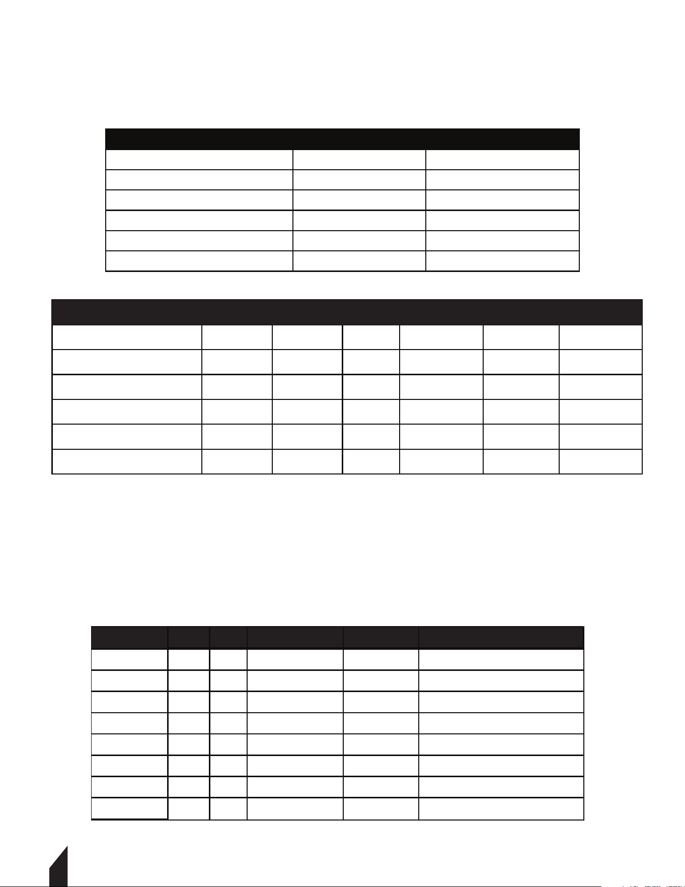
3. SPECIFICATIONS
Mode
Welding Current
Rod Types
Welding Rod Length
Diameter
Duraon of Load
Connector Type
MMA and TIG 210
40 - 120
6010- 7024
2.0 - 3.2 mm
3/32 - 1/4
60%
Dinse: DKJ 16-55
TWG210A WELDER
TWG210A GENERATOR
Engine
Horsepower
Voltage
Max Power
Rated Power
Generator Type
TOMAHAWK
15
120v
2200 Was AC
2000 Was AC
Inverter (PMG)
TWG210A ENGINE
Fuel Tank Capacity
Oil Tank Capacity
Fuel Type
Oil Type
6.34 qt
0.6 qt
91+ Octane
SAE10W-30
TWG210A DIMENSIONS
Length
Width
Height
Weight
28 in.
21 in.
23 in.
202 lbs.
NOTE: Tools runs simultaneously as welding
12
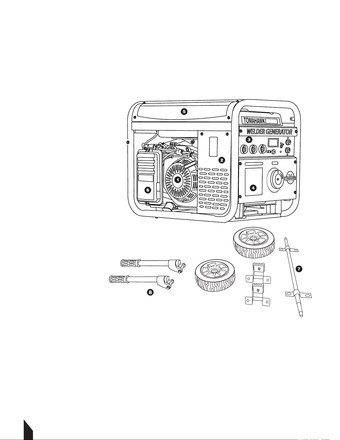
3.1 Welding Generator Parts
1. Engine
2. Generator
3. Welding Terminals
4. Control Panel
5. Fuel Tank
6. Air Filter
7. Wheel Kit Attachment
8. Handle Attachment
Tools Required
1. 10 mm Wrench
2. 13 mm Socket Wrench
3. 19 mm Socket Wrench
4. 04 mm Allen Wrench
3.2 Unpacking the Unit
Make sure to carefully remove all parts and accessories from the box. Ensure all parts listed
in the manual are in the box. Do not throw away the packaging or packing material until
you have inspected all parts and successfully operated the machine. Do not discard this
operations manual.
If any parts are missing or damaged, please contact TOMAHAWK® customer support by
email at support@tomahawk-power.com or call (866) 577-4476.
TWG210A
4. ASSEMBLY
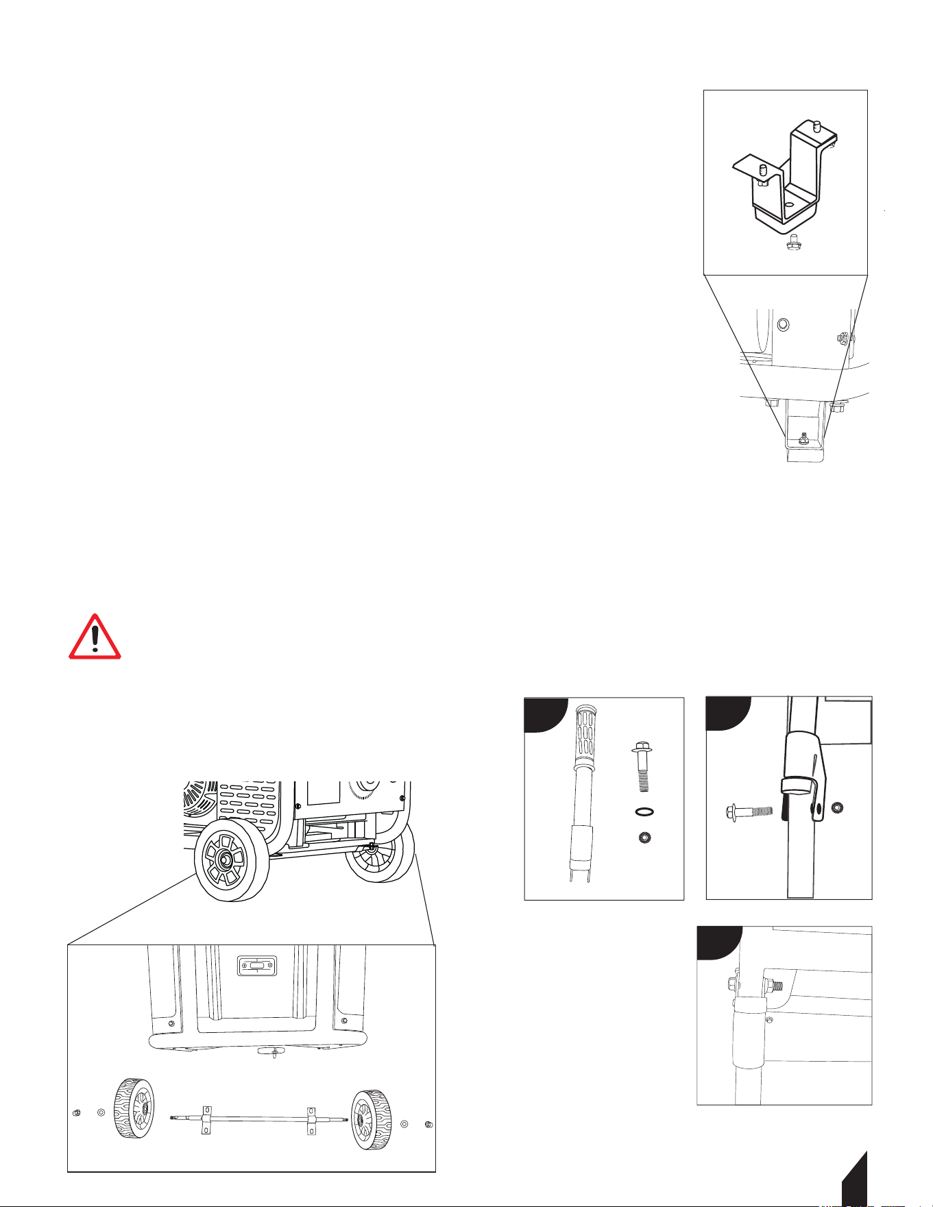
4.1 Wheel and Handle Kit Assembly
4.1.1 Attach the Feet(FIGURE 1):
• Align the studs on the foot bracket assembly with the holes
on the bottom of the generator frame.
• Secure in place with two hex flange nuts.
• Repeat for the other foot bracket assembly.
4.1.2 Assemble the Wheels(FIGURE 2):
• Insert the wheel axle through the bracket on the bottom of
the generator frame, secure in place with the pin.
• Slide one wheel onto a wheel axle and secure all-in place
with a washer and cap nut.
• Repeat steps for the other wheel.
4.1.3 Attach the Handle(FIGURE 3):
• Align the holes in the brackets on the handle with the holes
on the generator frame.
• Fasten in place using a bolt and a nut, one set on each side
of the handle.
13
WARNING Ensure all nuts and bolts are tightened
properly to avoid accidents. Do not over-tighten
screws as it may strip the threads.
WARNING
FIGURE 1
FIGURE 2
FIGURE 3
a
b
c
TWG210A
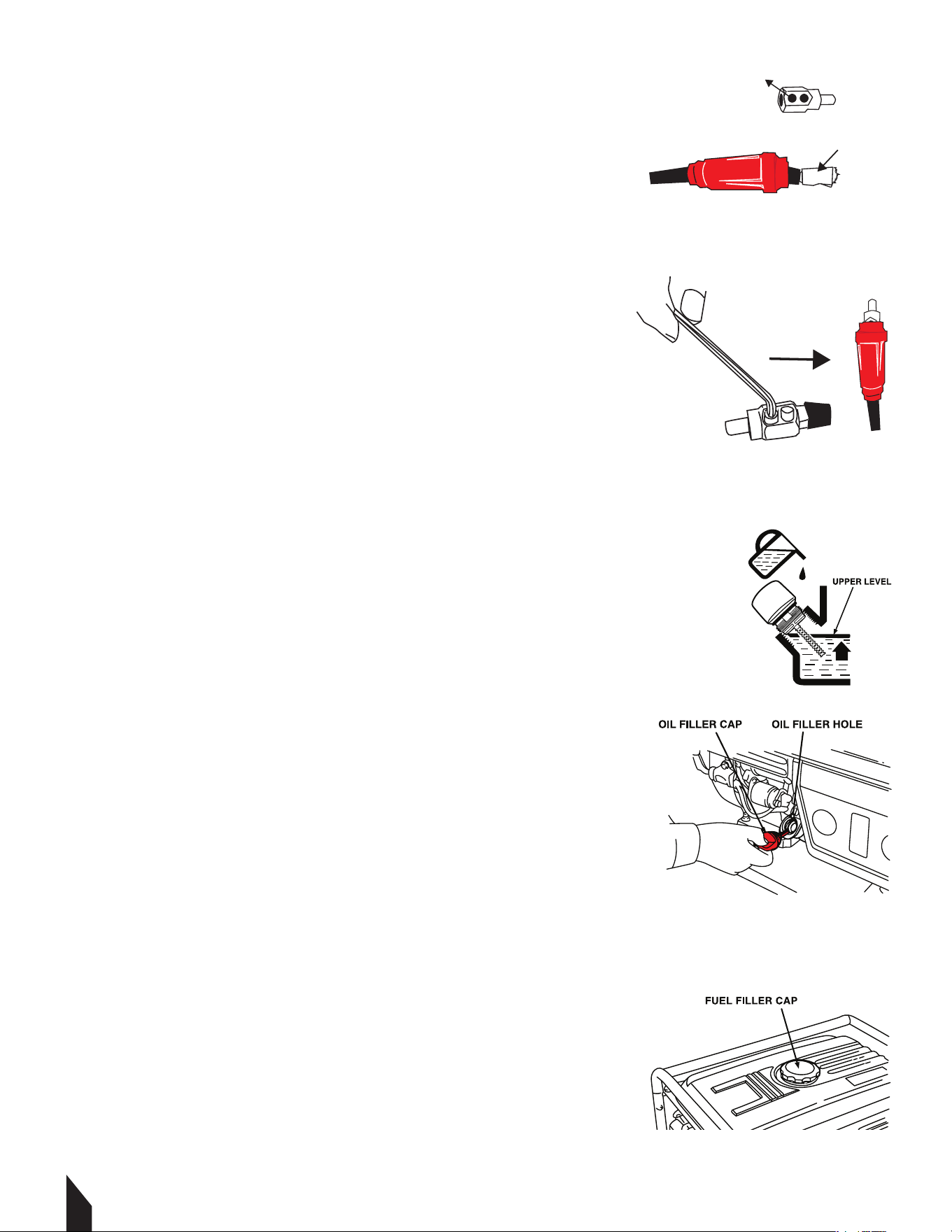
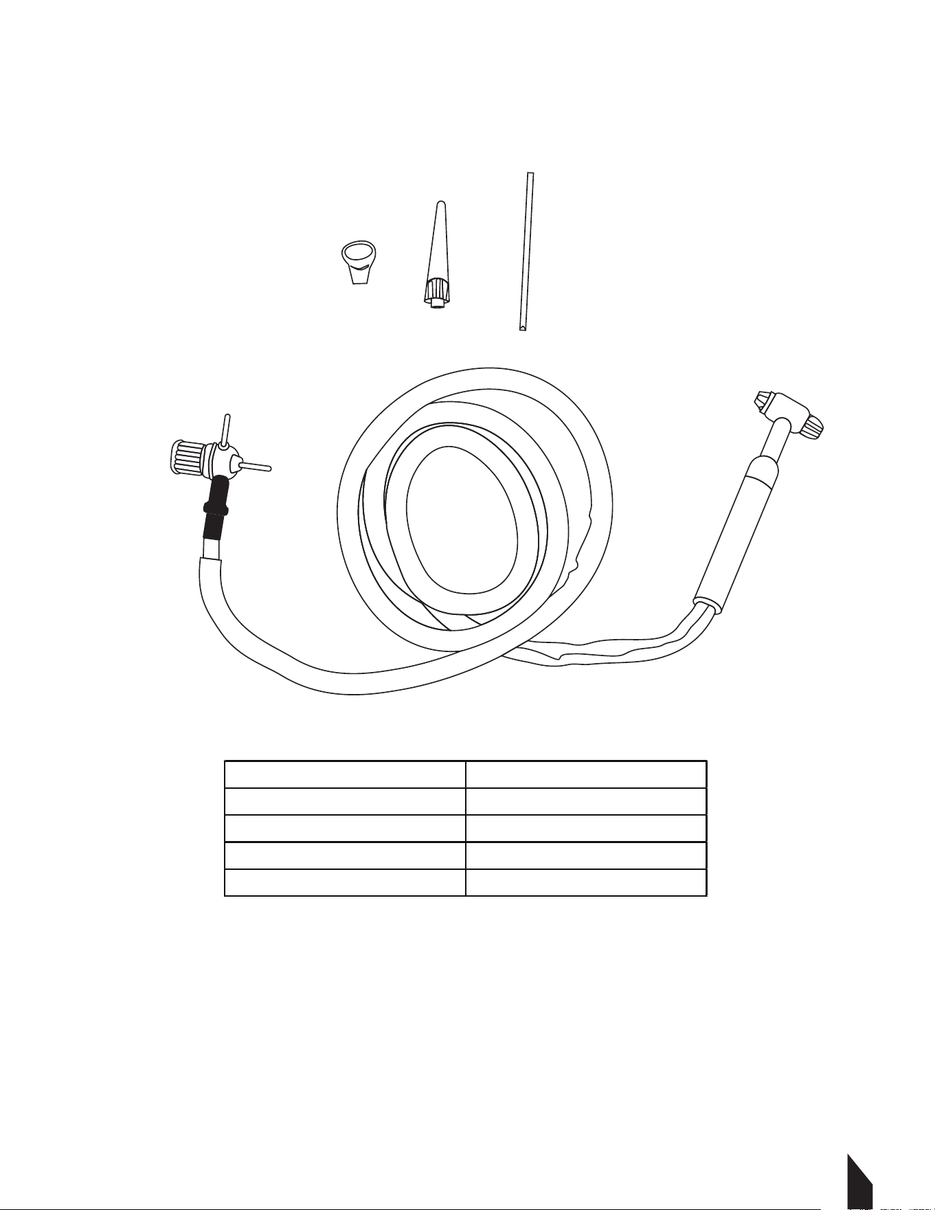
4.2 Cable Assembly
4.2.1 To connect the welding leads, begin by stripping
1” of rubber off the electrode holder cable. FIGURE 4.
4.2.2 Slide the red rubber guard over the top of the cable.
4.2.3 Wrap the exposed cable in a copper casing then insert
into the welding plug. FIGURE 4.
4.2.4 Tighten the cable in place with a 4 mm allen wrench.
4.2.5 Slide up the rubber guard to snugly cover up the plug.
FIGURE 5.
4.2.6 Repeat for the black rubber guard.
5. OPERATION
NOTE: Ensure both black and red rubbers are on before the
plug is attached.
5.1 Oil and Fueling
5.1.1 Remove oil filter cap. Then check the dipstick. If this is
your first time using the welder, fill the oil tank to the upper
limit with SAE10W30 4-Stroke motor oil. FIGURE 6.
NOTE: The oil tank capacity on this unit is 0.6 gallons
(0.56 liters). Do not overfill. FIGURE 6.
5.1.2 Reinstall oil cap securely.
5.1.3 Next, remove the fuel cap on top of the welder and
fill to the upper level with unleaded gasoline with a pump
octane rating of 89 or higher. FIGURE 7.
NOTE: The fuel tank capacity on this unit is
1.6 gallons (6 liters). Do not overfill.
5.1.4 Reinstall fuel cap securely.
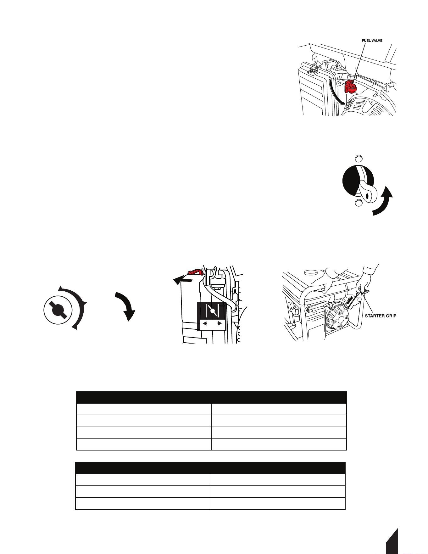
5.2 Starting Instructions
5.2.1 To start the welder, disconnect any tools or appliances
from the terminals or outlets.
5.2.2 Open the fuel valve. FIGURE 8.
14
FIGURE 7
FIGURE 6
FIGURE 5
FIGURE 4
WELDING PLUG
COPPER CASING
15
5.2.3 For a cold start, the choke will be in the CLOSED
position. To OPEN, pull on the choke lever ring firmly
position. FIGURE 9.
5.2.4 Turn the circuit breaker switch to the ON position.
FIGURE 10.
5.2.5 Turn the engine switch to START. Once the generator
is running turn it to the ON position.
FIGURE 11.
5.2.6 If the battery does not start. Hold the top handle
securely and pull the recoil starter grip until you feel
resistance, then pull briskly. FIGURE 12.
5.1.7 Once the welder is running smoothly, connect your
leads or devices to the proper outlets.
NOTE: Insert the ground lead into the negative terminal
and the electrode lead into either the 80 amp positive
terminal on the le or the 120 amp positive terminal on the right.
5.3 Recommended Information
DIMENSIONS
Length
Width
Height
197 mm (7 3/4 in) minimum
132 mm (6 3/18 in) minimum
188 mm (7 8/18O minimum
Nominal Voltage
BCI Group Size
Cold Crank Rang
Reserve Capacity
12V
U1
195 Amperee Minimum
8.8 Minutes Minimum
RECOMMENDATIONS
FIGURE 12
FIGURE 11
FIGURE 9
FIGURE 8
FIGURE 10
START RUN
OFF
ON
START
Engine Switch
OFF
Circuit Breaker
ON
NOTE: Turn Engine Switch to OFF. Connect Negative (-) cable last.
16
120 V DC Outlets
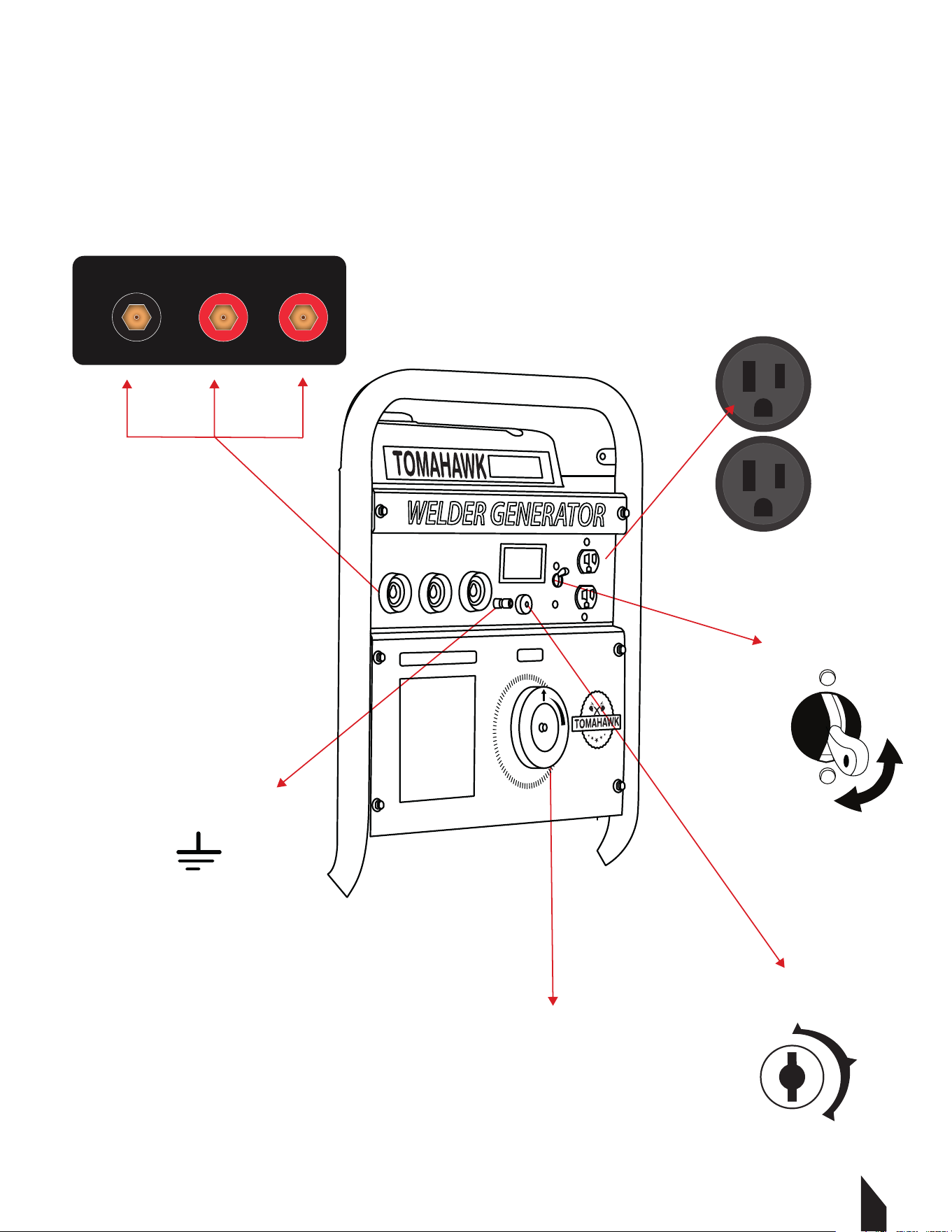
5.4 Welder Generator Panel Display
TWG210A
OFF
Circuit Breaker
ON
Earth Terminal
Engine Switch
Amperage Dial
Connections for ARC WELDING
+- +
50-130 AMP130-210 AMP
OFF
ON
START
17
6. SELECTING CABLE SIZES
6.1 Weld Cable Size and Total Cable (copper) Length in Weld Circuit Not Exceeding:
NOTE: These charts are a general guideline and may not apply to all applications. If cables
overheat, use the next larger size cable.
7. ELECTRODE SELECTION CHART
EP = Electrode Positive (Reverse Polarity)
EN = Electrode Negative (Straight Polarity)
ELECTRODE DC AC POSITION PENETRATION USAGE
6010
EP
ALL DEEP MIN PREP, ROUGH HIGH SPATTER
6011
EP X
ALL DEEP MIN PREP, ROUGH HIGH SPATTER
6013
EP, EN X
ALL LOW GENERAL
7014
EP, EN X
ALL MED SMOOTH EASY, FAST
7018
EP X
ALL MED LOW HYDROGEN, STRONG
7024
EP, EN X
FLAT HORIZ FILLET LOW SMOOTH, EASY, FASTER
NI-CL
EP X
ALL LOW CAST IRON
308L
EP X
ALL LOW STAINLESS
Welding Amperes
150 200 250 300 350 400
100
4 (20)
3 (30) 2(35)
1 (50)
1/0 (60)
1/0 (60)
150
2 (35)
1 (50) 1/0 (60)
2/0 (70) 3/0 (95) 3/0 (95)
200
1 (50) 1/0 (60)
2/0 (70)
3/0 (95) 4/0 (120)
4/0 (120)
250
1/0 (60) 2/0 (70) 3/0 (95)
4/0 (120) 2x2/0 (2x70) 2x2/0 (2x70)
300
2/0 (60) 3/0 (95)
4/0 (120)
2x2/0 (2x70) 2x3/0 (2x95) 2x3/0 (2x95)
10-100% AWG
100 FT OR LESS
Welding Amperes
100
150
200
250
300
4 (20)
3 (30)
2 (35)
1 (50)
1/0 (60)
4 (20)
3 (30)
3 (30)
2 (35)
1 (50)
10-60% AWG
60-100% AWG
1718
8. TIG TORCHES
8.1
Technical Specifications
Model
TIG300A
Max Amperage 300 Amps
Cooling Method Air-Cooled
Torch Cable Length 10 (3.3m)
Torch Style 17V
19
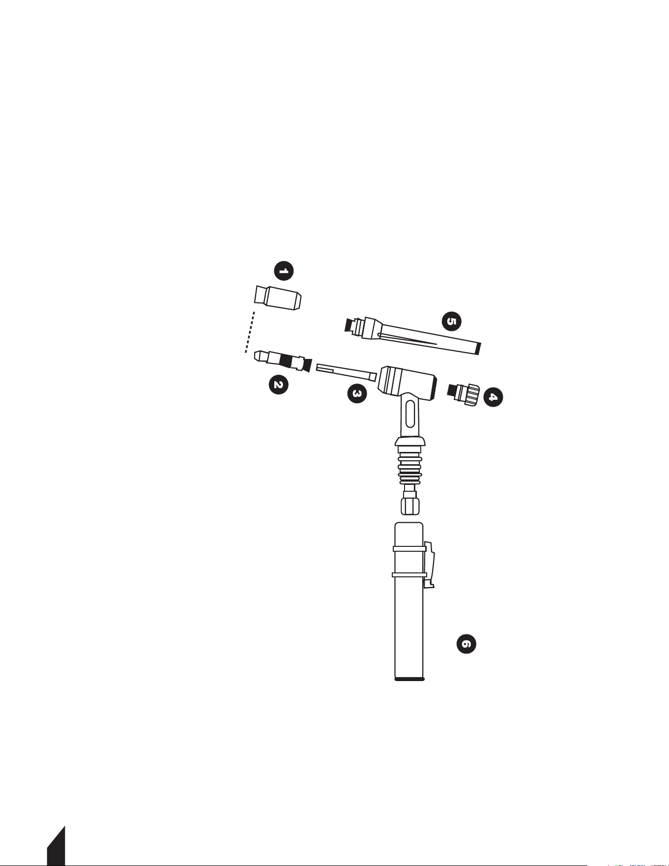
8.2
Torch Diagram
Қч Ceramic Nozzle
Ҡч Collect Body
Ңч Collect
Ҫч Short Back Cap
Үч Long Back Cap
Ұч TIG Torch Handle
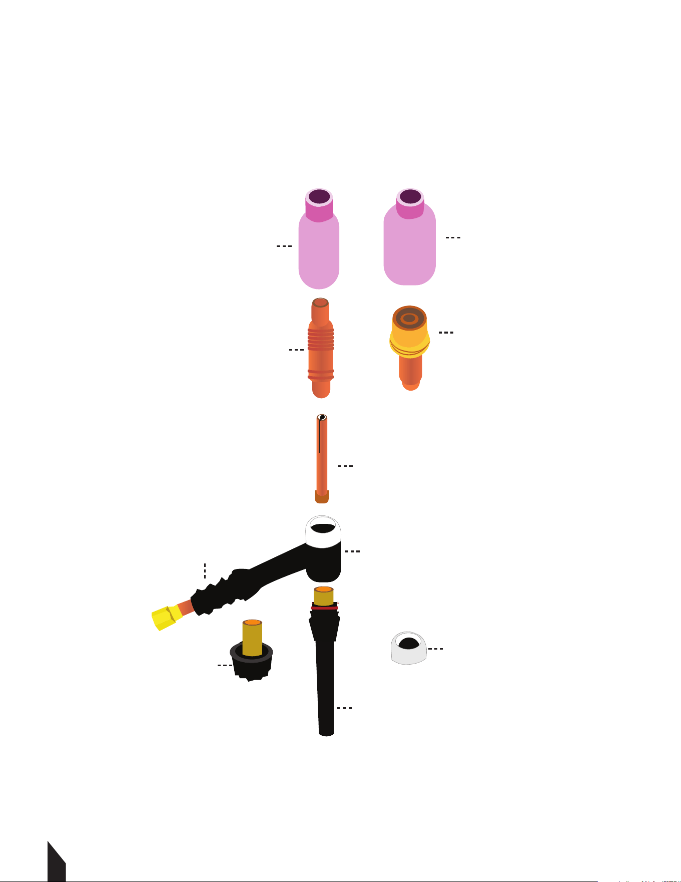
1720
Gas Lens Cup
Gas Lens Body
Ceramic Cup
Collect Body
Collect
Standard Heat Shield
Long Back Cap
Gas Lens Heat Shield
Short Back Cap
Torch Head
9. KNOW YOUR CROSS VALVE (+)
21
CAUTION
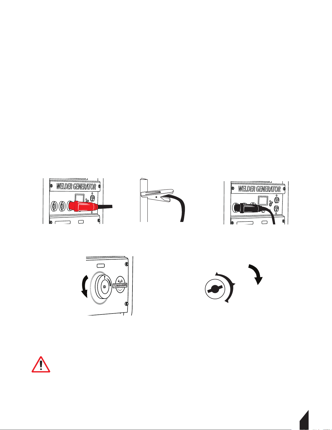
10. TIG TORCH INSTALLATION
10.1 Remove the ground cable and the electrode holder from the weld output connections.
Install the ground cable to the Positive (+) weld output connection. FIGURE 13.
10.2 Secure the ground clamp to the workpiece. FIGURE 14.
10.3 Connect a regulator to a bottle of ARGON gas. Then connect the gas connection from the
TIG torch to the regulator. ( Reference TIG torch and ARGON gas manufacturer manual for
proper connection method).
10.4 Connect the TIG torch weld cable to the Negative (-) weld output connection.
FIGURE 15.
10.5 Set the desired amperage on the amperage control knob on the front panel of the
welder. FIGURE 16.
10.6 Turn on the input power switch on the welder. FIGURE 17.
CAUTION Be aware that the TIG torch will be electrically HOT when
the Input Power Switch on the welder is turned on.
TWG210A
++-
TWG210A
++-
OFF
ON
START
Engine Switch
TWG210A
FIGURE 13 FIGURE 14 FIGURE 15
FIGURE 16
FIGURE 17

17
22
11. STORAGE
11.1 Clean and Inspect Thoroughly: Clean the generator to remove any dirt and grease
buildup. Inspect it for any signs of damage, such as loose bolts or frayed wires, and address
these issues as needed.
11.2 Prepare the Fuel System: Either drain the fuel tank and run the generator until it
stops to clear any fuel from the system, or add a fuel stabilizer if it will be stored for less
than six months. Always perform fuel-related tasks in a well-ventilated area to ensure
safety.
11.3 Lubricate and Store Correctly: Add a small amount of clean engine oil into the
cylinder and pull the starter gently to distribute the oil, preventing rust and corrosion.
Store the generator in a cool, dry, and well-ventilated space, such as a garage or outdoor
shed.
12. WELDING 101
12.1 Stick Welding Guideline
12.1.2 Preparation
• Safety First: Wear your welding helmet, gloves, and fire-resistant clothing to protect
yourself from sparks, UV rays, and heat.
• Clean the Workpiece: Use a wire brush or grinder to clean the metal surfaces you plan
to weld. This ensures better weld quality.
• Clamp the Workpiece: Secure your metal pieces firmly using clamps to prevent
movement during welding.
12.1.3 Setting Up the Welding Machine
• Select the Electrode: Choose an electrode suitable for the metal type and thickness,
detailed in Section 7.
• Adjust the Settings: Set the welding machine to the appropriate current for your
electrode and metal thickness. As a rule of thumb, use 1 amp per 0.001 inch of
electrode diameter.
12.1.4 Striking the Arc
• Hold the Electrode Holder: Hold the electrode holder at a slight angle (10-15 degrees)
to the workpiece.
• Strike the Arc: Tap the electrode against the metal surface as if lighting a match to
initiate the arc. Once the arc is established, maintain a consistent gap between
the electrode and the workpiece (about 1/8 inch).
23
12.1.5 Welding the Joint
• Maintain a Steady Speed: Move the electrode steadily along the joint,
keeping the arc length consistent.
• Control the Weld Pool: Watch the molten pool of metal and ensure it flows smoothly
into the joint.
• Weave or Stringer Bead: Depending on the joint type, use a weaving motion
(side to side) for wider joints or a stringer bead (straight line) for narrow joints.
12.1.6 Finishing the Weld
• Chip O the Slag: Aer completing the weld, let it cool slightly. Use a chipping
hammer to remove the slag covering the weld bead.
• Clean the Weld: Use a wire brush to clean the weld area, ensuring no slag or
debris remains.
12.1.7 Welding Tips
• Electrode Storage: Store electrodes in a dry place to prevent moisture absorption,
which can cause welding defects.
• Practice: Practice on scrap metal to improve your technique before welding
critical joints.
• Inspect Welds: Always inspect your welds for consistency, penetration, and defects.
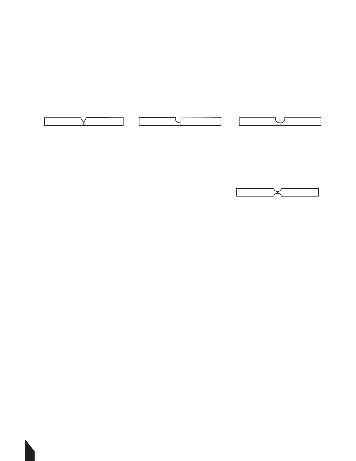
13. Types of Groove Welds
13.1 Single Groove Welds: Applied to one side, considered complete joint
penetration (CJP).FIGURE 18.
• Square Groove: Simple preparation, minimal deformation, used for thin plates.
CAUTION
CAUTION
CAUTION
CAUTION Always wear appropriate personal protective clothing.
CAUTION Weld current can damage electronic parts in vehicles. Disconnect
both battery cables before welding on a vehicle. Place work clamp as close tot
he weld as possible.
CAUTION
Weld current starts when electrodes touches work piece
FIGURE 18
24
• V-Groove: Easy to machine, can cause significant angular deformation, requires more
welding for thicker plates. FIGURE 19.
• J-Groove: Curved single-sided bevel, less filler material, good for thick plates.
FIGURE 20.
• U-Groove: Rounded sides, complex machining, reduces welding for very thick plates.
FIGURE 21.
13.2 Double Groove Welds: Apply a weld to both sides of the one of the single grove
welds joints( V,J, or U ). To create a symmetrical joint preparation. Example shown in
FIGURE 22.
NOTE: Groove angle and Root opening: Aects weld quality and penetration.
14. WELDING TEE JOINTS
Welding tee joints involves joining two pieces of metal at a right angle to form a "T" shape.
14.1 Steps to Weld Tee Joints
14.1.2 Prepare Materials
• Clean the metal surfaces to remove impurities. Use an angle grinder to remove mill
scale, dirt, and paint.
14.1.2 Position and Tack Weld
• Secure the pieces in place.
14.1.3 Lay the Bead
• Choose the appropriate welding method (stick, MIG, or TIG).
• Apply a consistent bead along the joint, ensuring proper penetration.
14.1.4 Grind and Finish
• Remove any slag or unevenness with a grinder.
• Finish the weld for a smooth appearance if necessary.
FIGURE 21FIGURE 20FIGURE 19
FIGURE 22

25
14.2 Types of Welds for Tee Joints
14.2.1 Fillet Weld: Common for basic joints.
14.2.2 Beveled Weld: Used for thicker materials for better penetration.
14.2.3 J-Weld: Provides additional strength with more material contact.
NOTE: Practice steady movements with the welding gun. Ensure proper alignment to
avoid weak joints.
15. WELD TEST
15.1 Destructive Testing
• Tensile Test: Measures the weld's strength by pulling it until it breaks.
• Bend Test: Assesses ductility and the presence of defects by bending the weld.
• The Hammer Test: Achieves this by striking the weld joint in the direction against the
weld. A good weld bends over but does not break.
• Macro Etch Test: Reveals internal weld structure by etching the cross-section with acid.
15.2 Non-Destructive Testing (NDT)
• Ultrasonic Testing (UT): Uses sound waves to detect internal defects.
• Radiographic Testing (RT): X-rays or gamma rays reveal internal flaws.
• Magnetic Particle Testing (MT): Detects surface and near-surface discontinuities in
ferromagnetic materials.
• Dye Penetrant Testing (PT): Identifies surface cracks using a dye and developer.
Significant Spaer Accumulaon
Irregular, Uneven Weld Bead
Small Crater Formaon During Welding
Excessive Overlap
Inadequate Penetraon
Fine Spaer
Uniform Bead
No Overlap
GOOD WELD
POOR WELD
Good Penetraon into Base Metal
Moderate Crater During Welding*

26
16. REPLACEMENT PARTS
16.1 For replacement parts and technical questions visit www.tomahawk-power.com or
scan the QR code on the front of this manual.
16.2 Not all equipment components are available for replacement. The illustrations within
this manual are a convenient reference to the location and position of parts
in the assembly sequence.
16.3 When ordering parts, the following may be required: equipment model number, serial
number/lot, date code, and description. The manufacturer reserves the right to make
design changes and/or improvements to equipment, parts, accessories, and manuals
without notice.
17. TROUBLESHOOTING
Porosity
Excessive Spatter
Incomplete Fusion
Arc length too long.
Reduce arc length.
Use dry electrode.
Workpiece dirty.
Clean the work surface by removing all
grease, oil, moisture, rust, paint, coatings,
slag, and dirt before welding.
Arc length too long or voltage too high.
Insufficient heat input.
Improper welding technique.
Increase amperage. Select larger
electrode and increase amperage.
Ensure Wires are Connected Properly.
Check That Led Is Displaying Green Light.
Reduce arc length or voltage.
Amperage too high for electrode.
Decrease amperage or select larger
electrode.
Damp electrode.
PROBLEM POSSIBLE CAUSES SOLUTION
Place stringer bead in proper location(s)
at joint during welding.
Adjust work angle or widen groove to
access bottom during welding.
Momentarily hold arc on groove side
walls when using weaving technique.
Keep arc on leading edge of weld puddle.

PROBLEM POSSIBLE CAUSES SOLUTION
Workpiece dirty.
Remove all grease, oil, moisture, rust,
paint, coatings, slag, and dirt from work
surface before welding.
Incomplete Fusion
Excessive heat input.
Excessive heat input.
Insufficient heat input.
Select lower amperage. Use smaller
electrode.
Increase and/or maintain steady
travel speed.
Increase amperage. Select larger
electrode and increase amperage.
Reduce travel speed.
Improper weld technique.
Choose a lower amperage setting. Use
a smaller electrode.
Increase and maintain a consistent
travel speed.
Increase and maintain a consistent
travel speed.
Lack of Penetration
No open circuit voltage at the
output studs; there is an open lead
in the weld circuit.
Excessive Penetration
Burn-Through
Generator out of
power or welding not
working.
Generator power is
available but unit
does not weld.
Engine runs erratically
or stops running.
Engine sputters
but will not start.
The engine requires servicing,
including the head, carburetor, filters,
oil, spark plug, and/or gas.
Faulty gas, filter, air cleaner, spark
plug, and/or breather.
Loose connection at the output stud.
The engine is not fully warmed up, and
the choke is in the fully open position.
Malfunctioning reactor.
Electrode holder is loose.
Workpiece is not connected.
Clean the slip rings when they are not
in use if they are dirty.
Inspect the rotor for any problems.
Check the stator field winding
for defects.
Test the capacitor for faults.
Check for faulty brushes.
Examine the field rectifier for issues.
Open the lead in the field circuit.
Contact an authorized
Tomahawk Power Service
Center
27
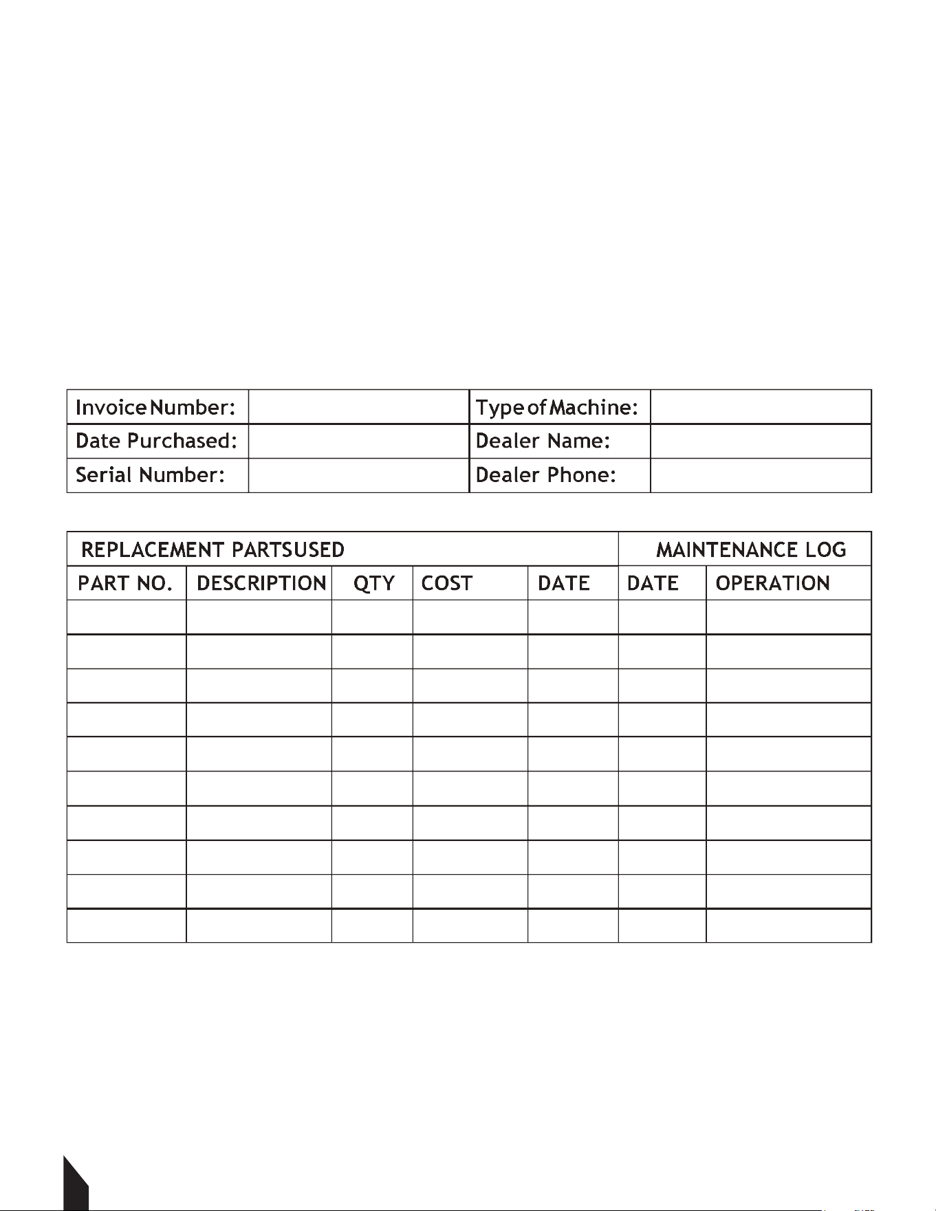
16. MAINTENANCE RECORD
TOMAHAWK® tools are assembled with care and will provide years of service when properly
maintained. Preventative maintenance and routine service are essential to the long life of
your welding generator. Adhere to reading through this manual thoroughly. You will find that
you can do some of the regular maintenance yourself. However, when in need of parts or
major service, be sure to contact a TOMAHAWK® Technician. For your convenience we have
provided this space to record relevant data about your TOMAHAWK® equipment.
28

18. EQUIPMENT WARRANTY
Your new TOMAHAWK® equipment is warranted to the original purchaser for a period of
one-year (12 months) from the original date of purchase. The TOMAHAWK® warranty is
against defects in design, materials and workmanship.
The following are not covered under the warranty:
19.1.1 Damage caused by abuse, misuse, dropping or other similar damage caused by or as
a result of failure to follow assembly, operation or user maintenance instructions.
19.1.2 Alterations, additions or repairs carried out by persons other than TOMAHAWK® or
their recognized agents.
19.1.3 Transportation or shipment costs to and from TOMAHAWK® or their recognized
agents, for repair or assessment against a warranty claim, on any machine.
19.1.4 Materials and/or labor costs to renew, repair or replace components due to fair
wear and tear.
19.1.5 TOMAHAWK® and/or their recognized agents, directors, employees or insurers will
not be held liable for consequential or other damages, losses or expenses in connection
with or by reason of or the inability to use the machine for any purpose.
Warranty Claims
Before submitting any warranty claim, you will need to register
your new TOMAHAWK® equipment through
www.tomahawk-power.com.
Follow the steps on page 3 or scan this QR codes to complete
the equipment registration. Aer registration is complete,
all warranty claims should firstly be directed to TOMAHAWK®
through the online Service Request form found
at www.tomahawk-power.com/pages/service-request.
20. SERVICES CENTERS
Our service centers are equipped to handle your equipment maintenance and repair needs
efficiently. With a network of authorized local service locations , you can find expert
support and genuine parts needed to keep your equipment running smoothly. All locations
are listed on the webpage https://tomahawk-power.com/pages/find-a-service-center.
29
Parts Manual
WELDER GENERATOR
MODEL NUMBER: TWG210A
30
TWG210A

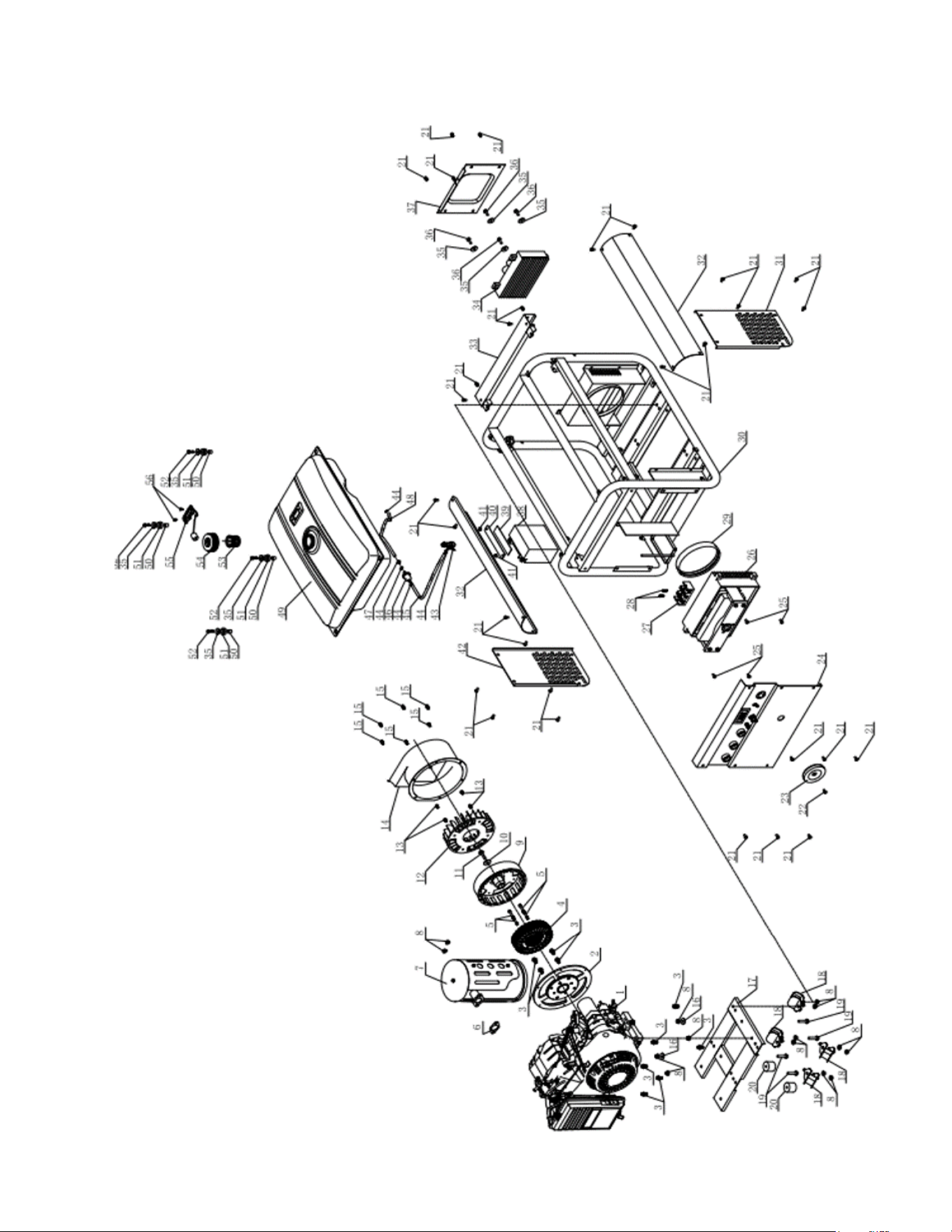
PARTS EXPLOSION

PARTS LIST
190F gasoline engine
Motor cover
Hexagon flange bolt M8X16
Stator
Hexagon flange bolt M6X55
Exhaust gasket
Muffler kit
Hexagon flange nut M8
Motor rotor
Level gasket 25X 10X3
Center motor hexagon flange bolt
Motor fan
Hexagon flange bolt M6X10
Motor cover
Hexagon flange bolt M6X8
Level gasket 24 8X1.5
Bracket
Shock-absorbing gasket
Hexagon flange bolt M8X40
Gasket
Hexagon flange bolt M6X12
Hexagon flange bolt M5X20
Current regulaon handle
C
ontrol panel kit
Hexagon flange bolt M6X16
Current regulator
Juncon box
Cross screw M5X30
1
2
3
4
5
6
7
8
9
10
11
12
13
14
15
16
17
18
19
20
21
22
23
24
25
26
27
28
1
10
1
4
1
1
1
14
1
1
1
1
4
1
6
2
1
4
4
2
30
1
1
1
4
1
1
2
No.
Description
QTY
Air guide seal
Machine frame
Side board I
Guard board
Acvity crosspiece
AC inverter
Level gasket 25X 6X1.5
Hexagon flange bolt M6X20
Inverter cover
Baery
Platen shim
Baery platen
Hexagon flange nut M6
Side board II
Fuel supply switch
Fuel tube clamp 9
Fuel tube I 8.5X2X410
Fuel filter
Fuel tube liner
Fuel tube II 8.5X2X190
Fuel tank 25L
Fuel tank posioning pin 12X 10X12
Fuel tank shock-absorbing gasket
Hexagon flange bolt M6X25
Fuel tank strainer
Fuel tank cap
Fuel level indicator
C
ross screw M5X15
29
30
31
32
33
34
35
36
37
38
39
40
41
42
43
44
45
46
47
48
49
50
51
52
53
54
55
56
1
1
1
2
2
1
1
8
4
1
1
1
1
4
1
1
1
1
1
1
1
1
4
4
1
1
1
1
No.
Description
QTY
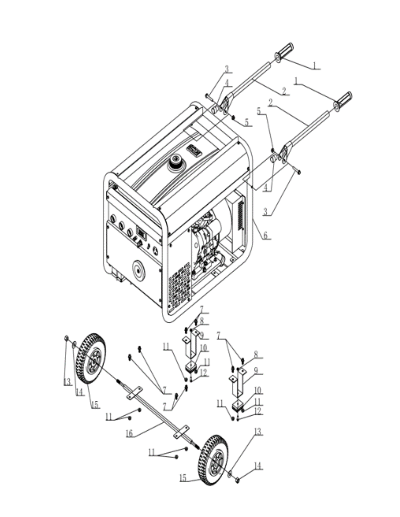
PARTS EXPLOSION

PARTS EXPLOSION
1 Rubber handle sleeve 2
2 Handle 2
3 Hexagon flange bolt M10X60 2
4 Spacer for handle 2
5 Hexagon flange nut M10 2
6 AC210 welder generator set 1
7 Hexagon flange bolt M8X16 5
8 Hexagon flange nut M6 2
9 Wheel bracket 2
10 Wheel bracket shim 2
11 Hexagon flange nut M8 8
12 Hexagon flange bolt M6X25 2
13 Level gasket φ28Xφ15X2.5 2
14 Hexagon cap nut M12 2
15 8' solid wheel 2
16 Wheel spindle 1
No.
Descripon
QTY

WORK SMARTER
NOT HARDER
For big areas and busy schedules, Tomahawk Push
Sweepers cover a wider path to reach more surface
area so you can finish sweeping faster around indoor
and outdoor spaces and on wet or dry surfaces!
Item #: TOS38
38" COMMERCIAL
PUSH SWEEPER
www.tomahawk-power.com

THE INDUSTRY'S
LIGHTEST 3KW
INVERTER
When the lights go out, have peace of mind that the
Tomahawk TG3000i Portable Generator will keep
your home powered. Each unit comes standard
with an easy fueling system, low oil sensor, voltage
regulation, and two 120 volt plugs and one 120 volt
twist lock outlet.
Item #: TG3000i
3000i WATT INVERTER
GENERATOR
www.tomahawk-power.com
Rammers
8 ft Hydraulic Steer, 35 HP Vanguard,
CVT Clutch, 180 RPM
10 ft Full Hydrostatic, 74 HP Hatz
Diesel
Part#:
TPT24H
TPT36H
TPT46H
Part#: JXPT30T
Part#:
TRT46V
TRT60V
2 ft Edger, Honda GX160, 0-28
o
Blade Pitch
3 ft, Honda GX160/GX270, 0-28
o
Blade Pitch
4 ft, Honda GX270/GX390, 0-28
o
Blade Pitch
HAVE QUESTIONS?
Contact us. We’re here to help!
Email us at [email protected]
Forward Plate Compactors
Reverse Plate Compactors
Part#:
TR68H
JX60H
eJX60H
TVSA-H
eTVSA
Part#:
Part#:
TPC80H
COMPACTION
Power Screeds
Porta-Trowels
Concrete Sprayers
Walk Behind Trowels
Ride on Trowels
Early Entry Saws
Part#:
6-16 ft Magnesium Blades
Honda GX35, Adjustable Handles
6-16 ft Magnesium Blades
36V/5 Ah Battery, Adjustable Handles
Part#:
TFS6H
TFS10H
Part#: TCS6.5
6" Blade Diameter, Blade Compatibility,
Honda GX120
10" Blade Diameter, Self Propelled,
Blade Compatibility, Honda GX270/GX390
CONCRETETROWELS
(866) 577-4476
TPC85H
TPC90H
TPC170H
TPC100H
TPC400H
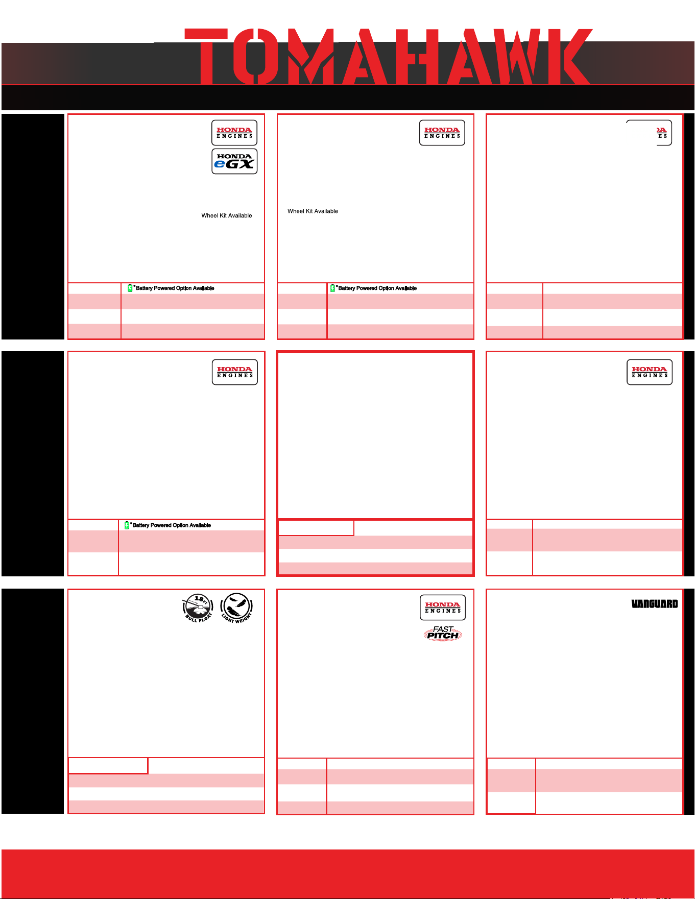
Equipment Guide
3,000 lbs/sq ft, Honda, 21”x17” Plate
3,200 lbs/sq ft, Honda, 23”x17” Plate
3,400 lbs/sq ft, Honda, 22”x20” Plate
3,500 lbs/sq ft, Honda, 19”×14” Plate
7,000 lbs/sq ft, Honda, 28”x20” Plate
11,690 lbs/sq ft, Honda, 32”x22” Plate
Lightweight at 40 lbs
Adjustable 18 ft Extension Bull Float Poles
30" Diameter, 4-Blade Assembly
Adjustable Blade Pitch from 0-28
o
Adjustable from 0-450 PSI
Handles 30% + Solids,1.8 HP 2 Stroke Motor,
24" Brass Wand 0.5 GPM, Fan Nozzle Included,
Spray 15,000 ft
2
in10 Minutes
3,550 lbs/sq ft, Honda GX120
3,350 lbs/sq ft, Honda GX100
3,350 lbs/sq ft, Honda GXE2.0S
Items Listed Includes Combo Blades

QUIET INVERTER SERIES
QUIET INVERTER SERIES
Welder GeneratorsPower Buggy
48V-20Ah Battery
Handles up to 8 cu ft or 660 lbs. Bucket Capacity
Hydraulic Bucket with 92
o
Tilt, 8 Hour Run Time
Snow Plow Attachment & Bucket Extender Available
Part#:
TGDR10
TSCP8
4,500 - 5,500 Watt Series
10,500 Watt Series
Concrete Scarifier
Floor Sweepers
Grinders and Scrapers
Part#: TSCAR-8H
Trash Water Pumps
Part#:
TW3H
TW4H
3" Pump, Honda GX270, 375 GPM,
Elevation: 89ft, Suction: 25ft
4" Pump, Honda GX390, 581 GPM,
Elevation: 92ft, Suction: 26ft
QUIET INVERTER SERIES
OUTDOOR POWER GENERATORSFLOORING
www.
tomahawk-power.com
(866) 577-4476
ASSEMBLED IN THE
PARTS SOURCED GLOBALLY
USA
TG2000i
TG3000i
2,000 - 3,300 Watt Series
Equipment Guide
10" Disc, 120V, 1/32" Per Pass,
11 AMP, 1.5 HP, 1,725 RPM
8" Blade, 120V, 11 AMP, 3/4 HP,
1,725 RPM, Carpet & Tile Remover
Honda GX160 Engine, Scarifies 350 - 500ft
2
/hr
OSHA Compliant Vacuum Port
8" Carbide Tungsten Drum Kit, 1/8" Per Pass
38" Working Width, Triple Broom
System, 14.5 Gallon
30" Working Width, Battery Powered
Triple Broom System, 13.5 Gallon
120 Amp Welder, 60% Duty Cycle,
2000w, Includes Wheel Kit
210 Amp Welder, 60% Duty Cycle,
2000w, Includes Wheel Ki
t
4,500w Max / 3,800w Rated
5,500w Max / 5,000w Rated, 120/220V
Run Time 8 Hrs @ 50% Load
CARB Compliant, GFCI
TG4500i
TG5500i
10,500w Max / 8,500w Rated
Voltage Selector, 120/220V
Run Time 14.5hrs @ 25% Load
CARB Compliant,
GFCI, CO Detector
TG9000i
2,200w Max / 2,000w Rated
3,300w Max
/ 3,000w Rated,
120/220V, 30 AMP Twist Lock
Run Time 8 Hrs @ 50% Load
CARB Compliant, GFCI 120v
6010-7024 Rods Compatible
Part#: TBUGGY300e
Part#:
TWG120A
TWG210A
Part#:
TOS38
eTOS30
Assorted Blade Choices Assorted Blade Choices
Assorted Brush Choices

TOMAHAWK®, LLC
San Diego, CA
Sales Support
(866) 577-4476
Equipment Support
(866) 577-4476
www.tomahawk-power.com
Tomahawk understands to keep a job-site running smoothly the proper equipment and
spare parts are needed at the drop of a hat. With same day shipping and faster
delivery times, count on Tomahawk to keep you powered throughout the day! With
long lasting parts and engines, Tomahawk equipment will be the star of your fleet for
years to come. Visit www.tomahawk-power.com to get started today!
Power Your World
FACEBOOK
facebook.com/TomahawkPowerUSA
YOUTUBE
youtube.com/TomahawkPower
INSTAGRAM
@tomahawkpower