TG2000i and TG3000i
INVERTER GENERATORS
Operations Manual
FIND THE HOW TO GUIDE ON

Thank you very much for choosing this Tomahawk Inverter Generator.
This Manual will instruct you how to operate and use the generator set safely and
properly. Please be sure to read it carefully before using.
All technical data and diagrams presented in this User's Manual are
consistent with the latest product at the time of publication (January 2020).
The contents of this manual may be slightly different from the specific
model. Tomahawk Power is entitled to make revisions at any time, and the
revised version will be developed without prior notice. The copyright of this
User's Manual belongs to Tomahawk Power and this Manual is not permitted
to be reproduced without written consent of Tomahawk Power, violators
may be prosecuted.
This Manual is a permanent part of the generator set. If the generator set is resold,
the Manual must be resold together with the generator set.

Table of Contents
Safety Warning …………………………………………………………..…. 1
I. Safety Instructions ……………………………………………………….. 2
II.
Parts and Components ……………………………………………………. 3
III. Control Functions ………………………………………………….…… 5
IV.
Before Using the Generator …………………………………………..…… 8
V. Starting up the Generator ………………………………………………10
VI. Shutting Down the Generator …………………………………………10
VII. Using the Generator ………………………………………………..… 11
VIII. Service and Maintenance …………………………………….………16
IX. Storage and Transport…………………………………………….…… 22
X. Troubleshooting …………………………………………………….…… 23
XI. Technical Specifications………………………………………………..… 24
XII. Circuit Diagram ………………………………………………………… 25
XIII. Generator Warranty ………………………………….……………........ 26

1
Safety Warning
Please read this Safety Warning in the User's Manual and the Safety Warning
decals on the generator set carefully.
The Safety Warnings can alert you to potential hazards that could harm you and
others. In front of each Safety Warning, there is one of four words "DANGER",
"WARNING", "ATTENTION", and "CAREFUL". Details are as follows:
DANGER
Failure to follow instructions will result in death
or serious injury.
WARNING
Failure to follow instructions will result in death or serious injury.
CAREFUL Failure to follow instructions will result in minor injury.
ATTENTION Failure to follow instructions will result in the damage to your
generator set and other components.
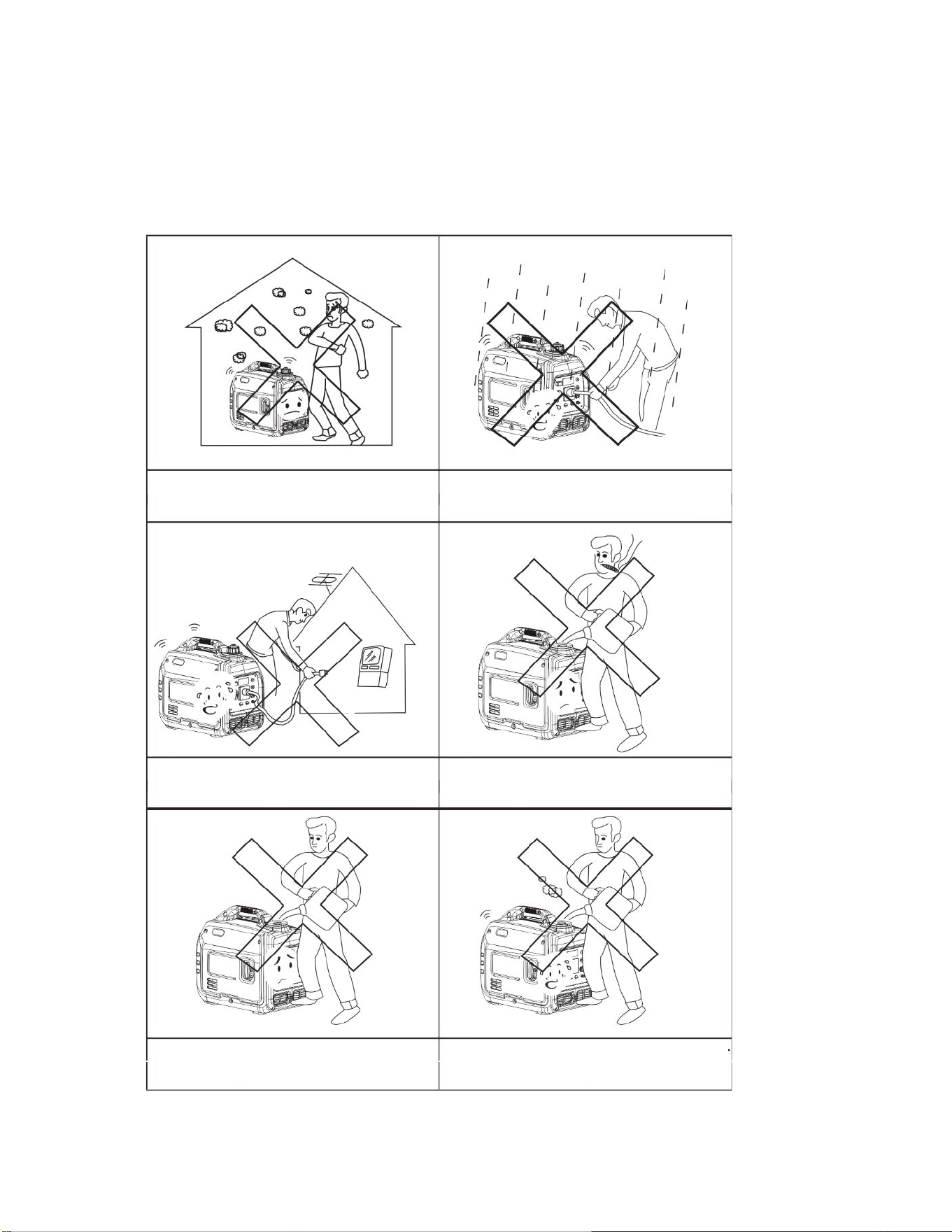
I. Safety Instructions
Before operating the generator, read and understand the Manual and
familiarize yourself with the safe operation procedures of the generator.
Do not use indoors.
Humid environments may effect
performance of the generator.
Do not connect it to household
appliances directly.
Always shut down generator before
refueling.
Do not spill when refueling. Clean
up any spills if they are made.
Do not smoke when refueling.
3
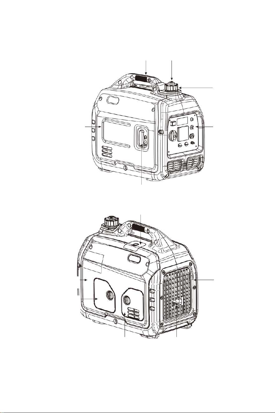
II. Parts and Components
Lifting handle
Left enclosure
Fuel tank cap
Control panel
Recoil starter handle
Spark plug cover plate
Side shield of
muffler
Right enclosure
Air filter cover
plate
Oil cover plate
Muffler
Ventilation knob
4
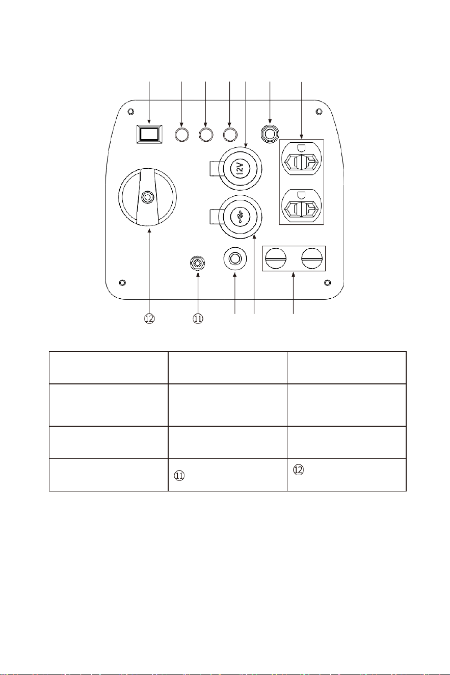
Control Panel
① ② ③ ④ ⑤ ⑥ ⑦
① Idle switch
② Oil alarm indicator
③ Overload indicator
④ AC output indicator ⑤ DC socket
⑥ AC circuit breaker
switch
⑦ AC socket
⑧ DC socket
⑨ USB socket
⑩ DC protection
Grounding terminal
3-in-One
combination
switch (ON, OFF, CHOKE)
⑩ ⑨
⑧
5
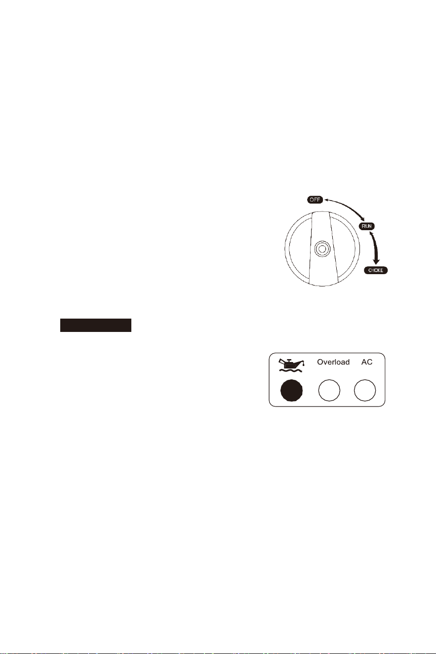
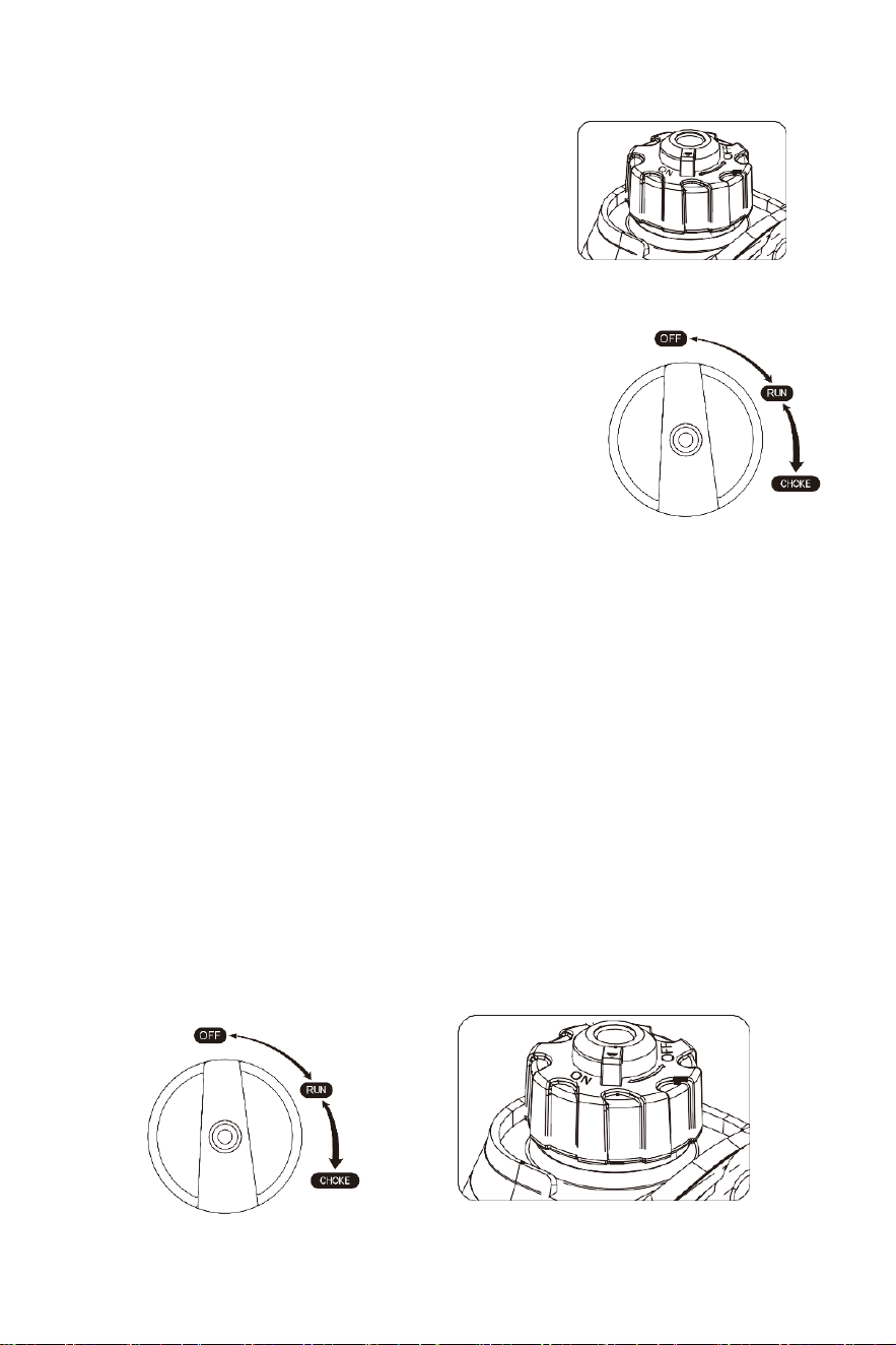
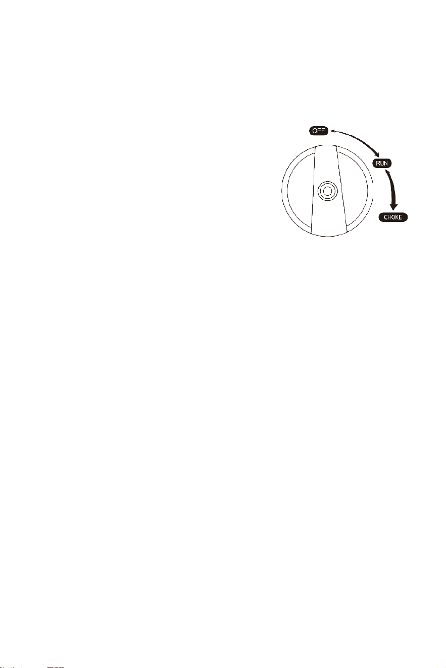
III. Control Functions
(
1)Three-in
-one
combination switch (also referred to as combination
switch)
RUN - After the engine has started, and been left for
5-10 seconds in the CHOKE position, rotate back to
the RUN position for proper function. Do not connect
an electrical load to the generator until the unit has
warmed up for at least 1 minute in the run position. If
the engine is hot, the unit can be started from the
RUN position.
ATTENTION
When the engine is hot, start the generator
in the run position.
(2) Oil indicator (red)
When the oil in the crankcase drops below
the safety line, the oil protection system will
automatically shut down the engine, and the
oil alarm indicator lights up; the engine can
be restarted only after the oil is filled to an adequate oil level.
Tip: In case the engine is unable to be started, turn the combination switch
to "RUN" position, and then pull startup handle. If oil indicator flashes a few
seconds, the oil volume is insufficient, fill oil and restart it.
(3) Overload indicator (red)
When the overload indicator lights up, the generator has detected that the
output of connected electrical equipment has been overloaded, causing
the frequency converter to be overheated or the AC voltage to rise. At this
moment, the AC protector will stop, to protect the generator from the
OFF - The ignition circuit is OFF and the engine will be unable to run.
CHOKE - When performing a cold start, rotate the switch to the
CHOKE position and pull the recoil until the engine starts. Be sure to
check for proper oil levels.

6
ON OFF
DC protection
connected electrical equipment. The AC indicator (green) is off and
overload indicator (red) lights up, but the engine will not stop running.
When overload indicator is on and the generator has no output, please take
following counter measures:
① Switch off electrical equipment connected, and shut down the generator.
② Reduce total power of electrical equipment connected to the range of
rated output.
③ Check whether there is any foreign matter blocking the air inlet, and
whether there is any abnormality in the related control components. If there
is any problem, eliminate it immediately.
④ After checking, restart the engine.
Tip: When using electrical equipment with a high starting current (such
as compressors, submersible pump, etc.), the overload indicator may start
to light up for a few seconds when started, but this is not due to the
failure mentioned earlier. If your equipment has variable speeds step
up the equipment to full load slowly.
(4) AC indicator (green)
The AC indicator light should be green when the output is normal.
(5)DC protection
If the current being drawn from the DC outlet is beyond the rated current, the
DC switch will automatically switch OFF to protect both the generator and the
connected equipment. To allow the current flow back to the DC outlet, press
the DC protection back to the ON position.
1) “ON” - Normal DC output
2) "OFF" - No DC output
ATTENTION
If DC protection is in the OFF status, reduce the load
of the
device connected to
the generator. If DC protection is still
in the
OFF status, stop using the equipment and consult your dealer.
7
AC recovery
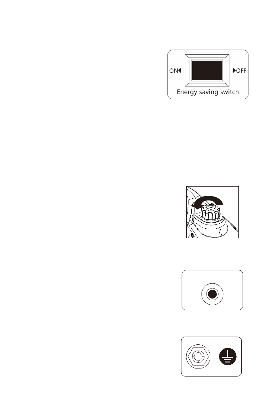
(6) ECO-MODE switch
(1) "ON"
When the ECO-MODE switch is switched
to
the "ON" position, the generator will
control the engine's output based on the load,
which will lead to more efficient fuel
consumption and reduced noise level.
2) "OFF"
When the ECO-MODE
switch is set to the "OFF" position, the engine will
run at the rated speed, regardless of the connected load.
Tip: Always run the generator with the ECO-MODE in the OFF position
when connecting devices that have a high starting amp requirement, such
as air compressors or submersible pumps.
(7)Fu
el tank cap
Remove fuel cap by unscrewing it counterclockwise.
(8)AC recovery
When the output is overloaded, the generator will protect itself and
automatically stop the electrical output. If this occurs, reduce the electrical
load and press the AC recovery switch.
(9)Grounding terminal
The grounding terminal shall be connected to the grounding wire to
prevent electric shock. If connected devices are grounded, be sure to
also ground the generator.
8
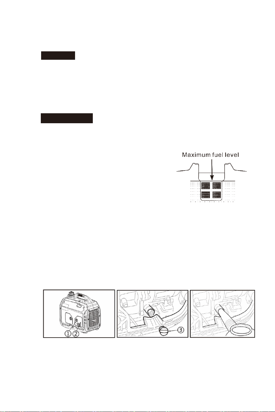
IV. Before Using the Generator
(1)
Fuel
DANGER
• Fuel is flammable and toxic, please read All Safety Instructions
carefully before fueling;
• Do not overfill the fuel tank
• After fueling, confirm that the fuel tank cap has been tightened.
ATTENTION
• After refueling, clean off gasoline residue with a clean cloth;
• Unleaded gasoline must be used, as
leaded gasoline can cause serious damage
to the internal parts of the generator;
• Remove fuel tank cap, and add gasoline
up to the red indicating line. Do not fill past
this line.
• Fuel tank capacity: 4L or 1 gallon.
(2)
Oil
This generator does not come with oil. Do not start up the generator
without filling with sufficient oil. Use SAE 10W-30 oil.
(3)
Place the generator onto a horizontal plane surface;
(4)
Unscrew the knob ① to remove oil cover plate ② ;
(5)
Unscrew oil dipstick ③;
6
)
Fill the tank with 0.35L oil or 11 ounces (SAE 10W/30 oil is
recommended, of which the grade is API standard Type SE or higher);
7
)
Reattach oil cover plate and tighten the oil dipstick.

9
(3)Pre-use inspection
WARNING
Before starting the generator, check the following components. If replacement
parts or repairs are needed, contact your local dealer.
Tip: Inspect your generator before every use
Pre-operation inspection
Fuel
• Check fuel level in fuel tank of the generator, add fuel if necessary.
Oil
• Check oil level of the generator, add oil if necessary;
• Check whether there is any oil leaking.
Issues when running the generator
• Check to make sure all breakers and switches are in the
correct position.
• Verify the connected devices are not overloading the
generator.
• Contact your local dealer if issues persists.
10
V. Starting up the Generator
(1) Disconnect all devices from the generator
(2) Switch ECO-MODE switch to "OFF"
(3) Turn ventilation knob of fuel tank cap to
"ON"
(4) Turn combination switch control to the
"CHOKE VALVE" position
eration
Choke
valve
Tip: If the engine is hot, start the generator in the "RUN" position
Tip: When pulling the recoil, be sure to keep a tight grip to prevent the
unit from falling over.
VI. Shutting Down the Generator
(1) Turn the combination switch to the "OFF" position;
(2) After the generator has completely cooled down, turn the entilation
knob on fuel tank cap to the "OFF" position.
(5) First gently pull recoil cord handle, until the cable is hooked tight,
and then pull with force.
(6) Once the generator starts, move the combination switch
to the "RUN" position.

VII. Using the Generator
(1) Proper conditions to run the generator
(2) Run in ambient temperature between 25 ~ 100 °F or -5 ~ 40°C;
(3) A
mbient humidity below 95%;
(4) To ensure proper function of the generator, operate at altitudes up
to 1 mile above sea level. If operation is needed at higher altitudes,
a carburetor adjustment may be needed.
11
Standard atmospheric condition
• Ambient temperature Tr: 298k (77°F or 25°C)
• Relative air humidity Фr: 30%
• Absolute atmospheric pressure Pr: 100kPa
• Every 30% of increase in relative humidity of air will reduce the power
of generator by about 1.5%
• Every 300 m rising of ASL will reduce the power the generator by
about 4.5%
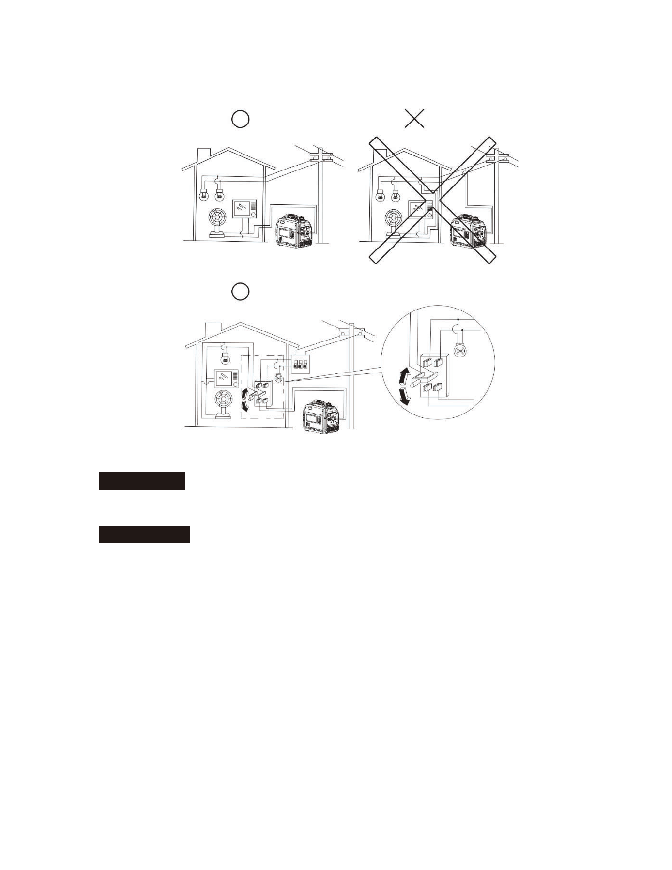
(2)Generator wiring
• When the generator is connected to a household power source as a
backup power supply, must be connected by a professional
electrician.
• After connecting the load to the generator, carefully check whether the
electrical connection is safe and reliable. An improper electrical
connection may cause generator damage or fire.
• Avoid connecting this generator to commercial power outlets.
• (xtension cableV PXVW be protected by a layer ofWRXJKHODVWLFUXEEHU
(IEC25) or
other substitutes
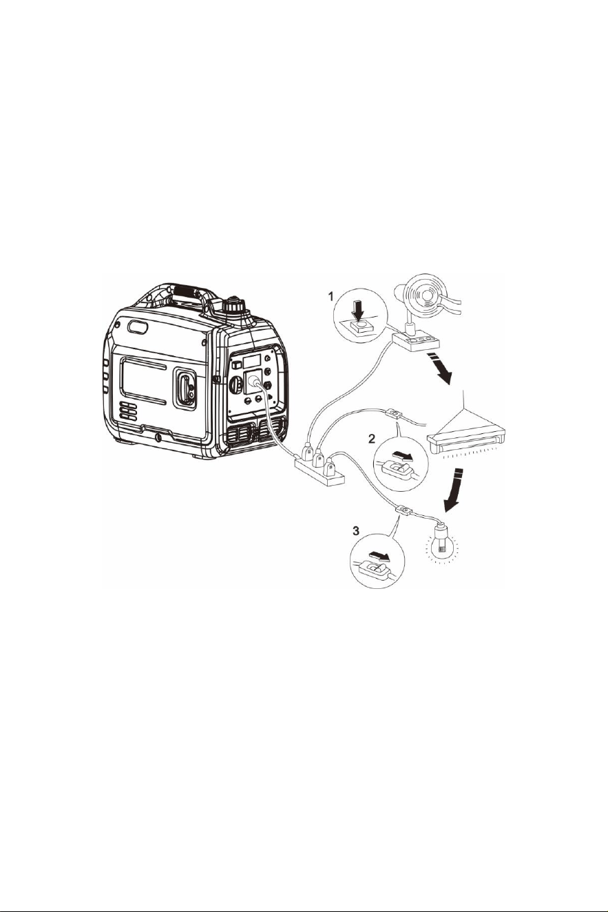
Connectio
n of AC power
WARNING
All electrical equipment PXVW be disconnected before
inserting the plug.
ATTENTION
• Make sure that all electrical equipment, including wires and plugs, arein
good condition before connecting to the generator;
• Make sure that all loads driven by the generator are within rated load
range;
• Make sure that WKH load current is within rated current range of WKH
ratedsocket.
Tip: Make sure that the generator set is grounded, and if WKHelectrical
equipment requires grounding, the generator set must be grounded.
ķ Start up the engine;
OK PROHIBITED
OK
13
② Turn ECO-MODE switch to "ON";
③ Insert the plug into
an AC outlet;
④ Make sure that the AC indicator is lit up;
⑤ Switch on the electrical equipment.
Tip: Before increasing engine speed, the ECO-MODE switch must
be switched to "OFF". If the generator set supplies power to multiple
loads or electrical equipment, start from large to small according to the
output of each electrical device.
(3)Generator grounding
In order to prevent any damage to the generator caused by electric shock or
improper electrical application, it is recommended that the generator is
grounded with a good conductor with insulating sheath.
① Please use grounding wire with sufficient electrical energy capacity;
② Connect one end of grounding wire to grounding bolt on control panel of
the generator set;
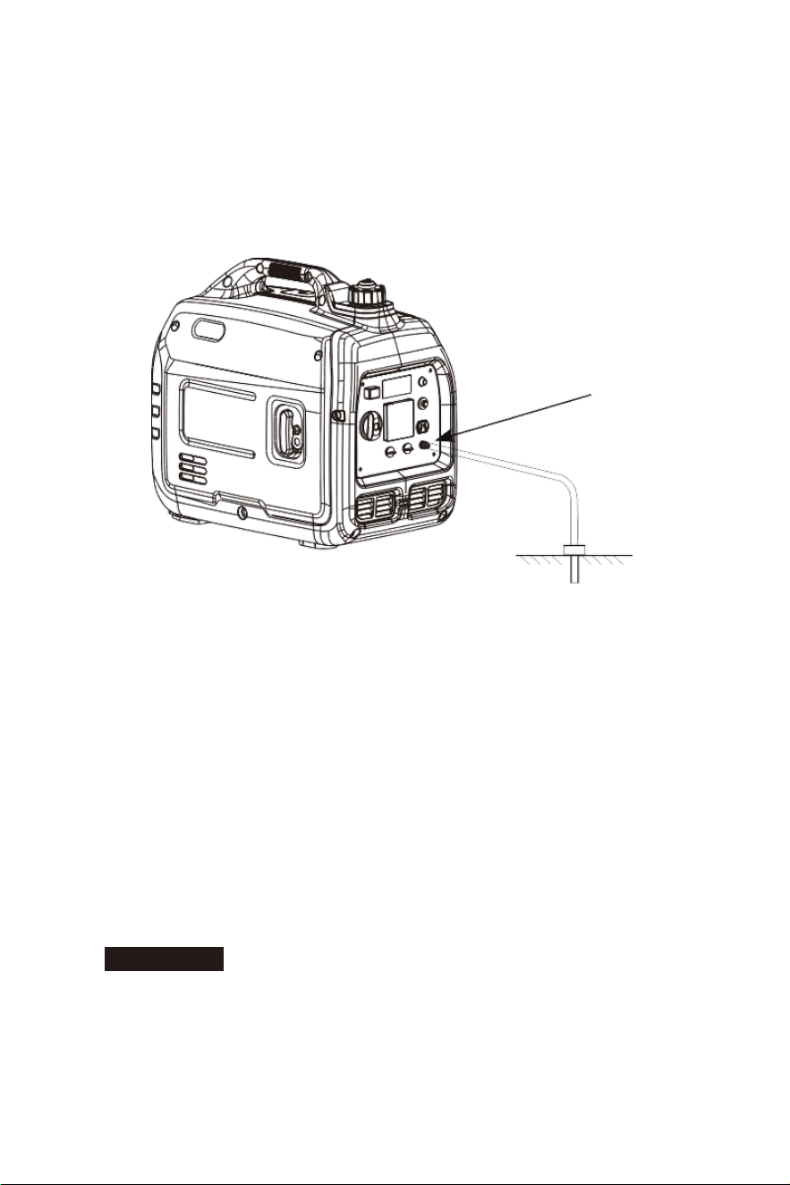
14
③ Insert grounding body (iron rod with a diameter of 3/16 inch to 1/2 inch)
8 inches below into the ground and lead it out with conductor;
④ Connect the other end of the grounding wire to the led wire of grounding
body.
(4)Battery charging
Tip:
• Rated DC voltage of this generator is 12V;
• After the generator is started, connect the battery to the generator;
• Before charging, make sure that DC protector has been switched on.
① Start up the generator.
② Connect red conductor of the battery to positive (+) terminal of the battery.
③ Connect black conductor of the battery to negative (-) terminal of the battery.
ATTENTION
• Make sure that red conductor of the charger is connected to
the positive terminal (+) of the battery, and black wire and negative
terminal shall not be connected reverse.
Grounding terminal

15
• The connection between the charger cable and battery terminal must be
reliable, try to prevent the generator from moving or becoming loose.
• Follow all steps in the User's Manual for proper operation.
• In the process of charging, if the current exceeds the value of the
rated current, the DC protector will shut off. Press the DC protector to
"ON" to restart charging. If the DC protector switches off again, stop
charging immediately and contact your dealer.
Tip: Measure specific gravity of electrolyte to determine whether the battery
is fully charged. In the case of full charging, the specific gravity of electrolyte
is between 1.26 and 1.28. It is recommended to check the specific
gravity of electrolyte at least once an hour, to prevent the battery
from being overcharged.
!
WARNING
Never connect or disconnect the the battery during charging. The spark
generated will ignite gas around the battery.
Battery contains sulfuric acid, which is toxic and could cause a fire. Please
avoid expose to skin, eyes, and clothing.
In the case of exposure to sulfuric acid, follow these steps:
• External exposure: flush with large amount of water, visit a hospital
• Ingestion: Drink large amount of water or milk, and drink milk, egg liquid or
vegetable oil containing magnesium oxide. Send victim to hospital
immediately
• Eye exposure: Flush with water for 15 minutes, and seek medical
treatment immediately.
Tip: The battery can generate explosive gas, keep it far away from sparks,
flames, cigarettes, etc. Keep ventilated when charging or using the
battery in a confined space.
Keep the batteries out of reach of children.
16
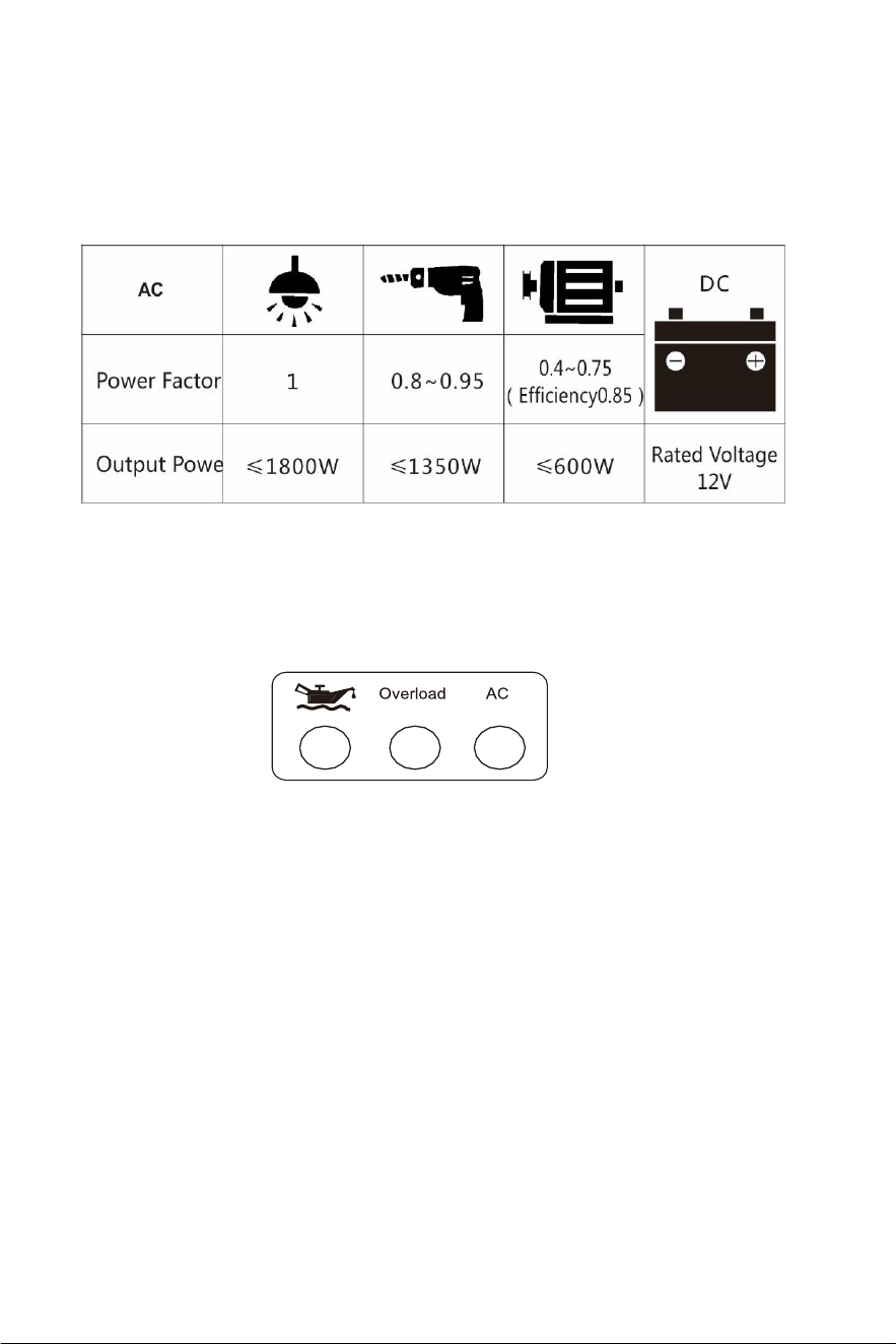
(5)Range of application
Before using the generator, make sure that the total load is within the
rated load range of the generator, otherwise the generator may be
damaged.
Tip:
• AC and DC can be used at the same time, but total the power amount
shall not exceed rated output power.
• When the total power exceeds the rated power, the overload indicator
will light up.
VIII. Service and Maintenance
Good maintenance and service is the best guarantee for safe, efficient, and
failure-free operation.
In order to keep the generator in good condition, you must inspect and maintain
it regularly. The maintenance schedule is as follows:

17
Maintenance cycle
Item
Each
First
maintenance is
carried out
after 1 month
or 20 hours of
use
Afterwards, the
maintenance is
carried out every
three months or
every 50 hours
Every year
or use of
100 hours
Engine oil
Check - fill
√
Replace
√
√
Gearbox
gear oil (if
any)
Check oil
level
√
Replace
√
√
Air cleaner
element
Inspection
√
clean
√
Replace
√
Settling bowl (if
any)
Clean
√
Spark plug
Clean -
adjust
√*
Spark eliminator
Clean
√
Idle speed (if any)
**
Check -
adjust
√
Valve clearance **
Check -
adjust
√
Fuel tank and
fuel filter ***
Clean
√
Fuel hose
Inspection
Every two years (Please replace if ecessary)
Cylinder head,
piston
Remove
carbon
deposit **
Displacement <225cc, every 125 hours; displacement
≥225cc, every 250 hours.
* These items shall be replaced if necessary;
** These items shall be maintained by the dealer authorized by the Company, unless the
user has proper tools and maintenance ability.
ATTENTION
• If unit is used regularly in high temperature or high load, oil must be
changed every 25 hours;
• If unit is used regularly in dusty or harsh environment, the air filter must be
cleaned every 10 hours. If necessary, the air filter must be replaced
every 25 hours;
• Unit must be maintained every maintenance cycle
• If maintenance cycle time has elapsed, perform the maintenance as soon
as possible as per the table above.
18
!
WARNING
Shut down the engine before performing any maintenance. The engine must
be placed in a horizontal position. In order to prevent the engine from starting
up, the spark plug cap must be separated from the spark plug.
Do not use indoors or use in a confined space, or other poorly ventilated
areas. Make sure that the work area is well ventilated. Exhaust from the
engine contains toxic gases and inhalation can cause shock, loss of
consciousness, and even death.
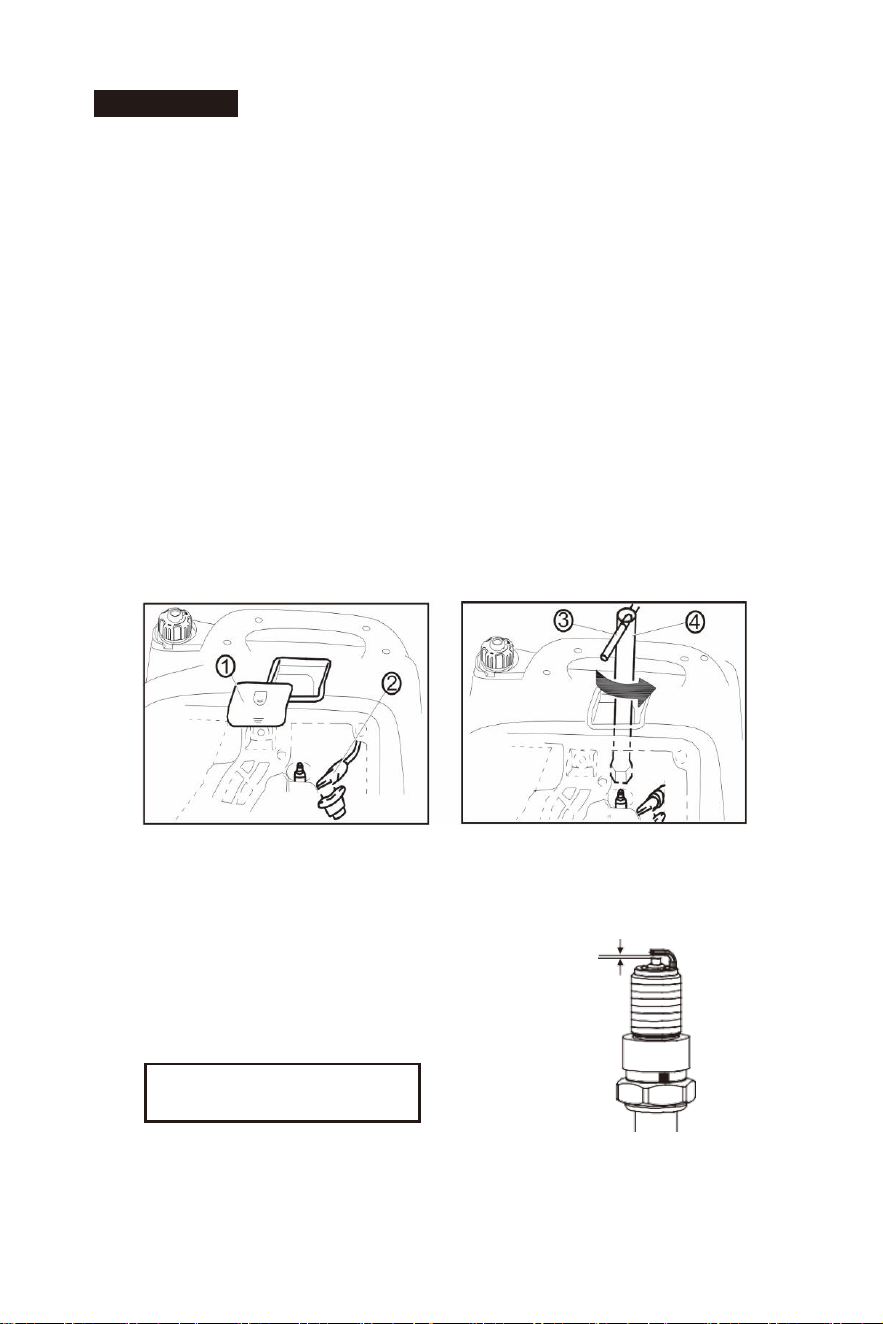
(1)Spark plug inspection
Spark plug is an important part of the generator, which must be inspected
regularly.
① Remove the cover and the spark plug cap of the generator;
② Insert the screwdriver into the sleeve, unscrew it counterclockwise, and
then remove the spark plug;
③ Check whether there is discoloration, and remove all carbon
deposits. Check whether there is discoloration on the ceramic cores
around the center electrode of the spark plug;
④ Check the model of spark
plug and clearance.
0.7~0.8mm
Tip: The spark plug clearance is required to be measured by a line
thickness gauge, and should be adjusted if necessary.
Standard spark: A5RTC
Spark plug gap: 0.7-0.8mm
19
⑤ Installation of spark plug
Tip: If there is no torque wrench when installing the spark plug, a better
estimation method is to screw it 1/4-1/2 turns by force after screwing it in place,
but the spark plug shall be screwed to specified torque as soon as possible.
(2)Adjustment of the carburetor
The carburetor is an important component of the engine. The adjustment shall
be carried out by a dealer with professional knowledge, professional data and
equipment, to ensure that the adjustment is proper.
(3)Replacement of oil
WARNING
Do not drain the oil immediately after turning off the generator.
Oil temperature is very high, when operating, take care to avoid injury.
1). Place the generator on a horizontal plane surface, start and run it for a
few minutes, to increase its temperature, and then shut down the engine
and turn the three-in-one combination switch knob to "OFF";
2). Unscrew the knob ①, to remove oil cover plate②;
3). Unscrew oil dipstick ③;
4). Place an oil pan under the engine, tilt the generator to pour out the oil;
5). Place the generator on a horizontal plane surface.
ATTENTION: When filling oil, do not tilt the generator to prevent any
damage by filling too much oil.
Spark plug torque: 12.5 N.m
①
②
③
20
6). Refill oil to a proper level;
7). Tighten oil dipstick, cover external cover plate and tighten the knob.
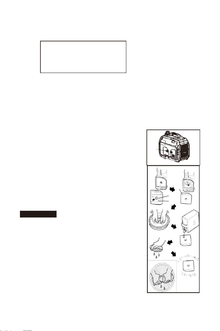
(4)Air filter
Dirty air filters may prevent air from flowing into the carburetor. In order to
prevent carburetor failure, replace the air filter regularly. If being used in a
dusty environment, it must be replaced frequently.
1). Unscrew the knob ①, to remove cover plate of the
air filter ②;
2). Remove screws ③, to remove cover plate of air
filter ④;
3). Remove foam filter element ⑤;
4). Clean foam filter element with cleaning
solvent and blow it dry;
5). Drip a few drops of oil on foam filter element and
squeeze off excess oil. The foam filter can be wet,
but there should not be any oil dripping.
ATTENTION
Be sure not to twist the foam
filter
forcibly to avoid damage.
6). Place foam element into air filter;
Tip: Make sure that the surface of foam filter
element is in close contact with the air filter, and
there is no gap. Be sure not to start the engine
before air cleaner is assembled, because it will
generate excessive toxic fumes and wear the
cylinder;
Recommended oil: SAE S10W/30
Oil grade: API Standard Model SJ
or Higher Volume: 12 FL OZ
①
②
⑤
③
④
21
7). Reassemble the air filter cap back to its original position, and tighten the screws;
8). Assemble air cleaner cover and tighten the knob.
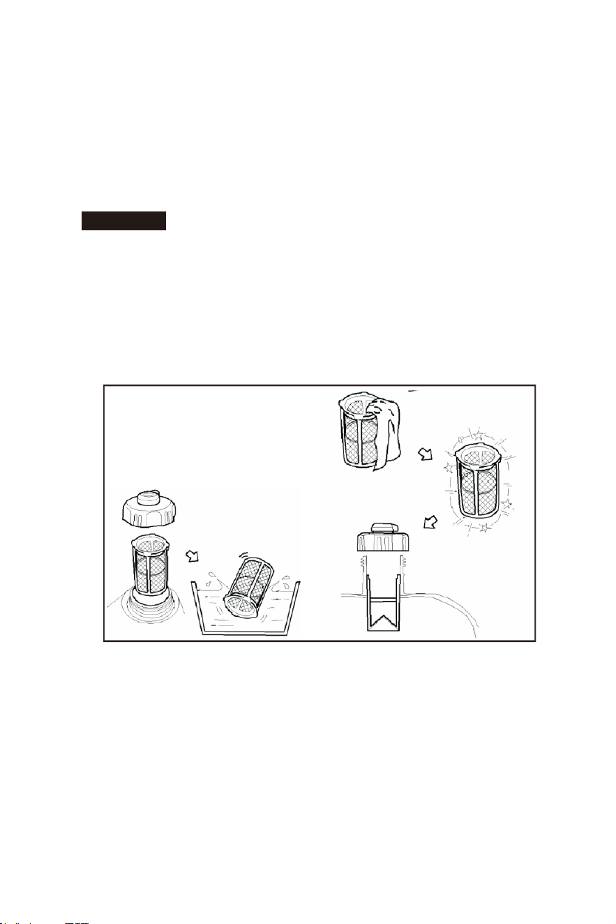
(5)Fuel filter screen
WARNING
Do not open the fuel tank of the generator in a place where
smoking or with flame.
1. Remove fuel tank cap and fuel tank filter screen;
2. Clean fuel tank filter screen;
3. Wipe filter screen dry, and put it back into fuel tank;
4. Reassemble fuel tank cap.
ATTENTION: Be sure the fuel tank cap is screwed on tight.
22
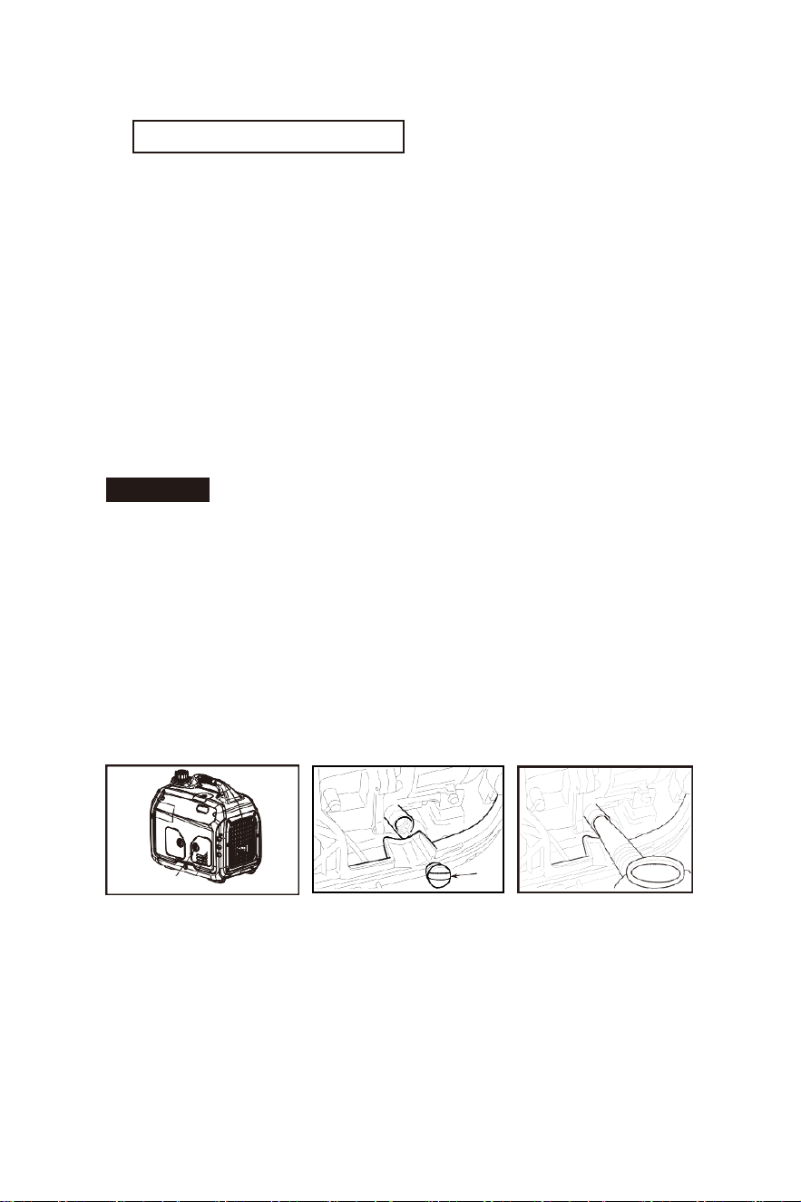
IX. Storage and Transport
(1)Generator storage
If it the generator is to be stored for a long period, follow these steps.
1). Turn the three-in-one switch to "OFF".
2). Open the fuel tank cap, to take out the fuel
filter screen. Pump all fuel in fuel tank into
special fuel tank, and then reassemble the
fuel tank cap back;
3). Start up the engine to burn off the fuel in the
carburetor, and then shut it down;
Tip: Do not connect any electrical equipment.
4). Remove bolts of right enclosure;
5). Unscrew fuel drain bolt on the carburetor, and drain fuel in the carburetor
into special fuel tank.
6). Turn three-in-one switch to "OFF";
7). Tighten fuel drain bolt;
8). Assemble right enclosure back, and tighten bolts;
9). After the engine is completely cooled, switch off the ventilation knob
10). Unscrew the oil dipstick and drain oil in the crankcase. Fill with new oil
to the oil limit, and then assemble oil dipstick.
11). Remove spark plug and pour a bit of clean oil into the combustion
chamber. Rotate the crankshaft a few turns, to distribute oil
evenly, and then reassemble spark plug;
12). Gently pull recoil cord until you feel resistance, allowing both the inlet
valve and exhaust valve to be closed;
13). Place the generator set in a clean and dry area.
(2)Generator transport
• When the generator set is to be transported, it must be ensured that
there is no risk of fuel spilling;

CALIFORNIA AND FEDERAL EMISSION CONTROL WARRANTY STATEMENT
YOUR WARRANTY RIGHTS AND OBLIGATIONS
The California Air Resources Board, the United States Environmental Protection Agency
and Tomahawk Power, LLC are pleased to explain the emissions control system
warranty on your 2018-2019 small engine/equipment (SORE). In the United States and
California, new small engine/equipment must be designed, built and equipped to meet
the State's stringent anti-smog standards. Tomahawk Power, LLC must warrant the
emissions control system on your small engine/equipment for the periods of time listed
below provided there has been no abuse, neglect or improper maintenance of your small
engine/equipment.
Your emission control system may include parts such as the carburetor, fuel-injection
system, the ignition system, catalytic convertor, fuel tanks, fuel lines, fuel caps, valves,
canisters, filters, vapor hoses, belts, clamps, connectors, and other associated emission-
related components. For engines less than or equal to 80 cc, only the fuel tank is subject
to the evaporative emission control warranty requirements of this section.
(California only)
Where a warrantable condition exists, Tomahawk Power, LLC will repair your small off-
road engine/equipment at no cost to you including diagnosis, parts and labor.
MANUFACTURER'S WARRANTY COVERAGE:
The emissions control system is warranted for two years. If any emissions-related part on
your small engine/equipment is defective, the part will be repaired or replaced by
Tomahawk Power, LLC
OWNER'S WARRANTY RESPONSIBILITIES:
As the small engine/equipment owner, you are responsible for the performance of the
required maintenance listed in your owner's manual. Tomahawk Power, LLC
recommends that you retain all receipts covering maintenance on your small engine/
equipment, but Tomahawk Power, LLC cannot deny warranty solely for the lack of
receipts or for your failure to ensure the performance of all scheduled maintenance.
As the small engine/equipment owner, you should however be aware that Tomahawk
Power, LLC may deny your warranty coverage if your small engine/equipment or a part
has failed due to abuse, neglect, improper maintenance or unapproved modifications.
You are responsible for presenting your small engine/equipment to distribution center or
service center authorized by Tomahawk Power, LLC as soon as the problem exists. The
warranty repairs should be completed in a reasonable amount of time, not to exceed 30
days.
29

If you have any questions regarding your warranty rights and responsibilities, you should
contact Tomahawk Power, LLC customer service representative at 1-866-577-4476 or
Email: support@tomahawk-power.com .
DEFECTS WARRANTY REQUIREMENTS
(a)The warranty period begins on the date the small engine/equipment is
delivered to an ultimate purchaser.
(b)General Emissions Warranty Coverage. Tomahawk Power, LLC warrants to the
ultimate purchaser and each subsequent owner that the engine/equipment is:
(1) Designed, built, and equipped so as to conform with all applicable regulations
adopted by the Air Resources Board; and
(2) Free from defects in materials and workmanship that causes the failure of a
warranted part for a period of two years.
(c)Subject to certain conditions and exclusions as stated below, the warranty on
emissions related parts is as follows:
(1)Any warranted part that is not scheduled for replacement as required maintenance in
your Owner’s Manual is warranted for the warranty period stated above. If the part fails
during the period of warranty coverage, the part will be repaired or replaced by
Tomahawk Power, LLC according to Subsection (4) below. Any such part repaired or
replaced under warranty will be warranted for the remainder of the period.
(2)Any warranted part that is scheduled only for regular inspection in your Owner’s
Manual is warranted for the warranty period stated above. Any such part repaired or
replaced under warranty will be warranted for the remaining warranty period.
(3)Any warranted part that is scheduled for replacement as required maintenance in your
Owner’s Manual is warranted for the period of time before the first scheduled
replacement date for that part. If the part fails before the first scheduled replacement, the
part will be repaired or replaced by Tomahawk Power, LLC according to Subsection (4)
below. Any such part repaired or replaced under warranty will be warranted for the
remainder of the period prior to the first scheduled replacement point for the part.
(4)Repair or replacement of any warranted part under the warranty provisions herein
must be performed at a warranty station at no charge to the owner.
(5)Notwithstanding the provisions herein, warranty services or repair will be provided at
all of our distribution centers that are franchised to service the subject small engine/
equipment.
(6)The small engine/equipment owner must not be charged for diagnostic labor that
leads to the determination that a warranted part is in fact defective, provided that such
diagnostic work is performed at a warranty station.
(7)Tomahawk Power, LLC is liable for damages to other small engine/equipment
components proximately caused by a failure under warranty of any warranted part.
(8)Throughout the small engine/equipment warranty period stated above, Tomahawk
Power, LLC will maintain a supply of warranted parts sufficient to meet the expected
demand for such parts.
(9)Any replacement part may be used in the performance of any warranty maintenance
or repairs and must be provided without charge to the owner. Such use will not reduce
the warranty obligations of Tomahawk Power, LLC
30

(10)Add-on or modified parts that are not exempted by the Air Resources Board may not
be used. The use of any non-exempted add-on or modified parts by the ultimate
purchaser will be grounds for disallowing a warranty claims. Tomahawk Power, LLC will
not be liable to warrant failures of warranted parts caused by the use of a non-exempted
add-on or modified part.
(11)The manufacturer issuing the warranty shall provide any documents that describe
that manufacturer's warranty procedures or policies within five working days of request
by the Air Resources Board.
EMISSION WARRANTY PARTS LIST
The repair or replacement of any warranted part otherwise eligible for warranty coverage
may be excluded from such warranty coverage if Tomahawk Power, LLC demonstrates
that the small engine/equipment has been abused, neglected, or improperly maintained,
and that such abuse, neglect, or improper maintenance was the direct cause of the need
for repair or replacement of the part. That notwithstanding, any adjustment of a
component that has a factory installed, and properly operating, adjustment limiting
device is still eligible for warranty coverage. The following emissions warranty parts for
each engine family list is covered.
For engine families greater than 80cc:
(1)Fuel Metering System:
(a)Gasoline carburetor assembly and its internal components
(b)Carburetor gaskets
(c) Fuel tank
(d) Fuel Line
(e) Fuel Line Fittings
(f) Clamps
(g) Pressure regulator (if equipped)
(h) Mixer assembly and its internal components (if equipped)
(2) Air Induction System including:
(a)Intake pipe/manifold
(b)Air cleaner
(3)Ignition System including:
(a)Spark plug
(b)Ignition coil
(4)Catalytic Muffler Assembly including:
(a)Muffler gasket
(b)Exhaust manifold
(c)Catalytic converter
(5)Crankcase Breather Assembly including:
(a) Breather connection tube.
(6) Fuel tank evaporative emissions control system including:
(a) Purge Valves
(b) Carbon Canister
(c) Canister Mounting Brackets
(d) Fuel Cap
(e) Fuel Tank
(7)Miscellaneous items Used in Above Systems including:
(a) Switches
(b) Hoses, belts, connectors, and assemblies.
(8)Air injection system
31

(a) Pulse valve
For engine families less than or equal to 80cc:
(1)Fuel Metering System:
(a)Gasoline carburetor assembly and its internal components
(b)Fuel filter (if so equipped)
(c)Carburetor gaskets
(d)Fuel pump (if so equipped)
(2) Air Induction System including:
(a)Intake pipe/manifold
(b)Air cleaner
(3)Ignition System including:
(a) Spark plug
(b)Ignition module/coil
(4)Catalytic Muffler Assembly (if so equipped) including:
(a)Muffler gasket
(b)Exhaust manifold
(5)Crankcase Breather Assembly including:
(a) Breather connection tube.
(6)Miscellaneous items Used in Above Systems including:
(a) Switches
(b) Hoses, belts, connectors, and assemblies.
(7) Fuel tank evaporative emissions control system including:
(a) Fuel Tank
The warranty is provided in accordance with the “California AND FEDERAL Emission
Control Warranty Statement”.
32

INVERTER SERIES INVERTER SERIES
HAVE QUESTIONS?
Contact us. We’re here to help!
Email us at [email protected]
3,550 lbs/ft Vibratory Rammer
Part#: TR68H
3.6 HP Honda GXR120 Engine
Easily achieve a 100% compaction rating
3-in-One Fuel System with carburetor protection
13” x 11” plate for narrow trenches and corners
3 Year Engine Warranty & 1 Year Product Warranty
3,400 lbs/ft Plate Compactor
Part#: TPC90H
5.5 HP Honda GX160 Engine
Easily achieve a 100% compaction rating
22” x 20” cold, rolled steel beveled base plate
Includes 3.5 gallon water tank for asphalt compaction
3 Year Engine Warranty & 1 Year Product Warranty
3,000 lbs/ft Plate Compactor
Part#: TPC80 & TPC80H
6 HP Kohler CH260 & 5.5 HP Honda GX160 Engines
Easily achieve a 100% compaction rating
16.5” x 21.5” plate for narrow trenches and corners
Optional Honda Engine model: TPC80H
3 Year Engine Warranty & 1 Year Product Warranty
COMPACTION
6.5 Gal Backpack Concrete Sprayer
Part#: TCS6.5
Maintain constant, adjustable pressure up to 450 PSI
Achieve superior concrete finishes with even spraying
Spray 15,000 sq ft in less than 10 minutes
Compatible with major manufacturer wands
1 Year Product Warranty
1.6 HP Vibratory Concrete Screed
Part#: TVSA-H
1.6 HP Honda GX35 Engine
Aluminum Magnesium blades available from 8ft - 14ft
Finish concrete 4X faster than other screed methods
360° adjustable handle placement
3 Year Engine Warranty & 1 Year Product Warranty
6” Early Entry Green Concrete Saw
Part#: TFS6H
5.5 HP Honda GX160 Engine
Maximum cutting depth of 1 3/16 inches
OSHA compliant vacuum port for dust collection
Includes 6” early entry concrete blade
3 Year Engine Warranty & 1 Year Product Warranty
FINISHING
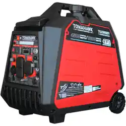
Part#: TG2000i
2000 Max Watts, 1600 Rated Watts
Run Time of 8 hours on 1 gallon of gas
OSHA and GFCI Compliant
Parallel technology capable for double the power
2 Year Product Warranty
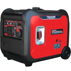
3500 Watt Inverter Generator
Part#: TG3500i
3500 Max Watts, 3000 Rated Watts
Run Time of 20 hours on 3.5 gallon of gas
OSHA and GFCI Compliant with Electric Start
Parallel technology capable for double the power
2 Year Product Warranty
4000 & 7000 Watt Generators
Part#: TG4000 & TG7000
4000 / 7000 Max Watts, 2500 / 5500 Rated Watts
Voltage Selector gives Full Wattage for 120V or 240V
Run Time of 8 hours at 50% Load
OSHA and GFCI Compliant
2 Year Product Warranty
GENERATORS
2000 Watt Inverter Generator
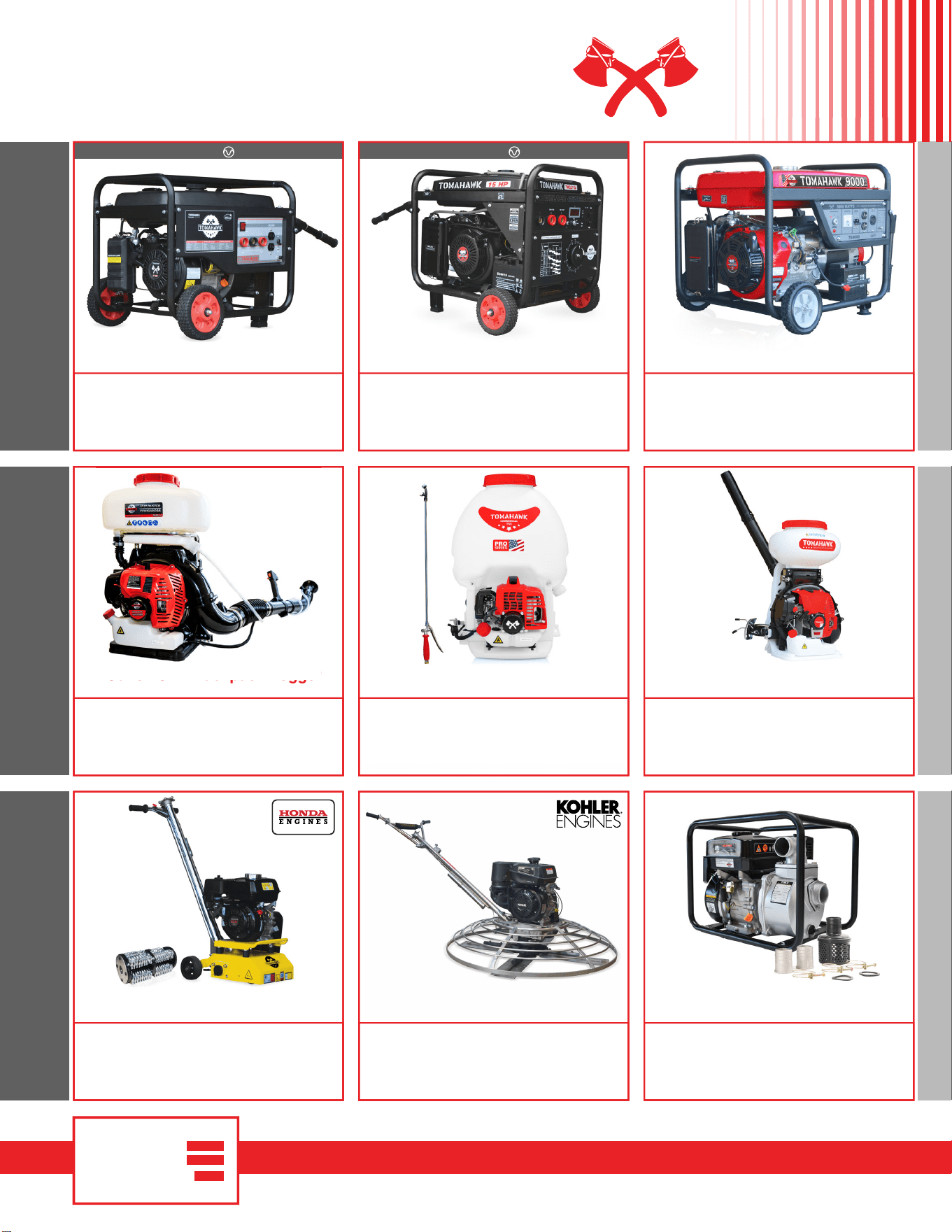
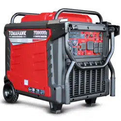
9000 Watt Generators
Part#: TG9000
9000 Max Watts, 8500 Rated Watts
Run Time of 10 hours at 50% Load
7 gallon fuel tank for extended use
Electric Key Start with battery included
2 Year Product Warranty
8” Gas Powered Concrete Scarifier
Part#: TSCAR8H
5.5 HP Honda GX160 Engine
Remove traffic lines at 800 - 1,000 linear ft/hr
Tungsten Carbide Blade Kit Available
OSHA approved dust port for silica vacuum removal
3 Year Engine Warranty & 1 Year Product Warranty
36” & 46” Concrete Power Trowel
Part#: TPT36K & TPT46K
6 HP Kohler CH260 & 14 HP Kohler CH440 Engines
Adjust trowel blade pitch from 0-28°
60-115 RPM rotor speed for superior concrete finishes
Includes float pan and trowel blades
3 Year Engine Warranty & 1 Year Product Warranty
2” and 3” Trash Water Pumps
Part#: TW2 & TW3
Moves liquids at a rate up to 9,240 gallons/hour
Handle solids up to 0.6"
Cast iron impeller for smooth performance
6.5 HP engine protected by rugged all purpose frame
1 Year Product Warranty
INVERTER SERIES
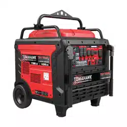
120 Amp Portable Welder Generator
Part#: TWG120A
Steady 120 Amp DC welding output
60% Duty Cycle for extended use
Suitable for welding rods from 6010 to 6013
Includes wheel kit for job site portability
2 Year Product Warranty
INVERTER SERIES
210 Amp Portable Welder Generator
Part#: TWG210A
Steady 50 - 210 Amp DC welding output
60% Duty Cycle for extended use
Suitable for welding rods from 6010 to 7024
Electric Key Start with battery included
2 Year Product Warranty
3.7 Gallon 3HP Backpack Fogger
Part#: TMD14
Turbo Boosted Pump with 40ft + Horizontal Reach
Sprays 1 acre in 30 minutes
10X Faster than Manual Pump Sprayers
Converts to Leaf Blower with 200 MPH Air Velocity
1 Year Engine Warranty & 1 Year Product Warranty
5 Gallon 1.8HP Backpack Sprayer
Part#: TPS25
Reach Up to 30ft Horizontal Reach
Sprays 1 acre in 15 minutes
10X Faster than Manual Pump Sprayers
450 PSI Commercial Grade Pump
1 Year Engine Warranty & 1 Year Product Warranty
4 Gallon 3HP Backpack Spreader
Part#: TGS30
AND MORE WELDING / POWERPEST CONTROL
www.tomahawk-power.com
(866) 577-4476
Reach Up to 30ft Horizontal Reach
Covers 1 acre in less than 30 minutes
20X Faster than Manual Broadcast Spreaders
Converts to Fogger with Liquid Tank Accessory
1 Year Engine Warranty & 1 Year Product Warranty
ASSEMBLED IN THE
PARTS SOURCED GLOBALLY
USA
7 Gallon 3HP Backpack Fogger

Tomahawk Power, LLC
San Diego, CA
Sales Support
(866) 577-4476
Equipment Support
(866) 577-4476
www.tomahawk-power.com
Tomahawk understands to keep a job-site running smoothly the proper equipment and
spare parts are needed at the drop of a hat. With same day shipping and faster
delivery times, count on Tomahawk to keep you powered throughout the day! With
long lasting parts and engines, Tomahawk equipment will be the star of your fleet for
years to come. Visit www.tomahawk-power.com to get started today!
Power Your World