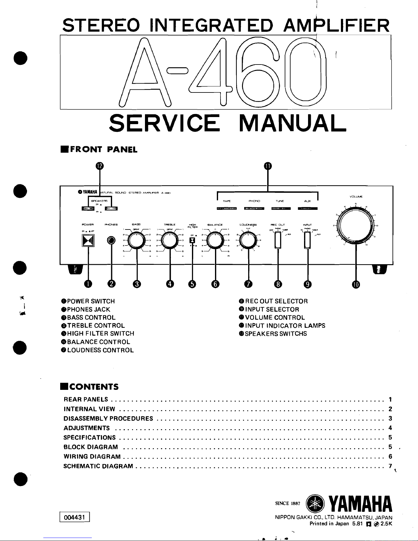
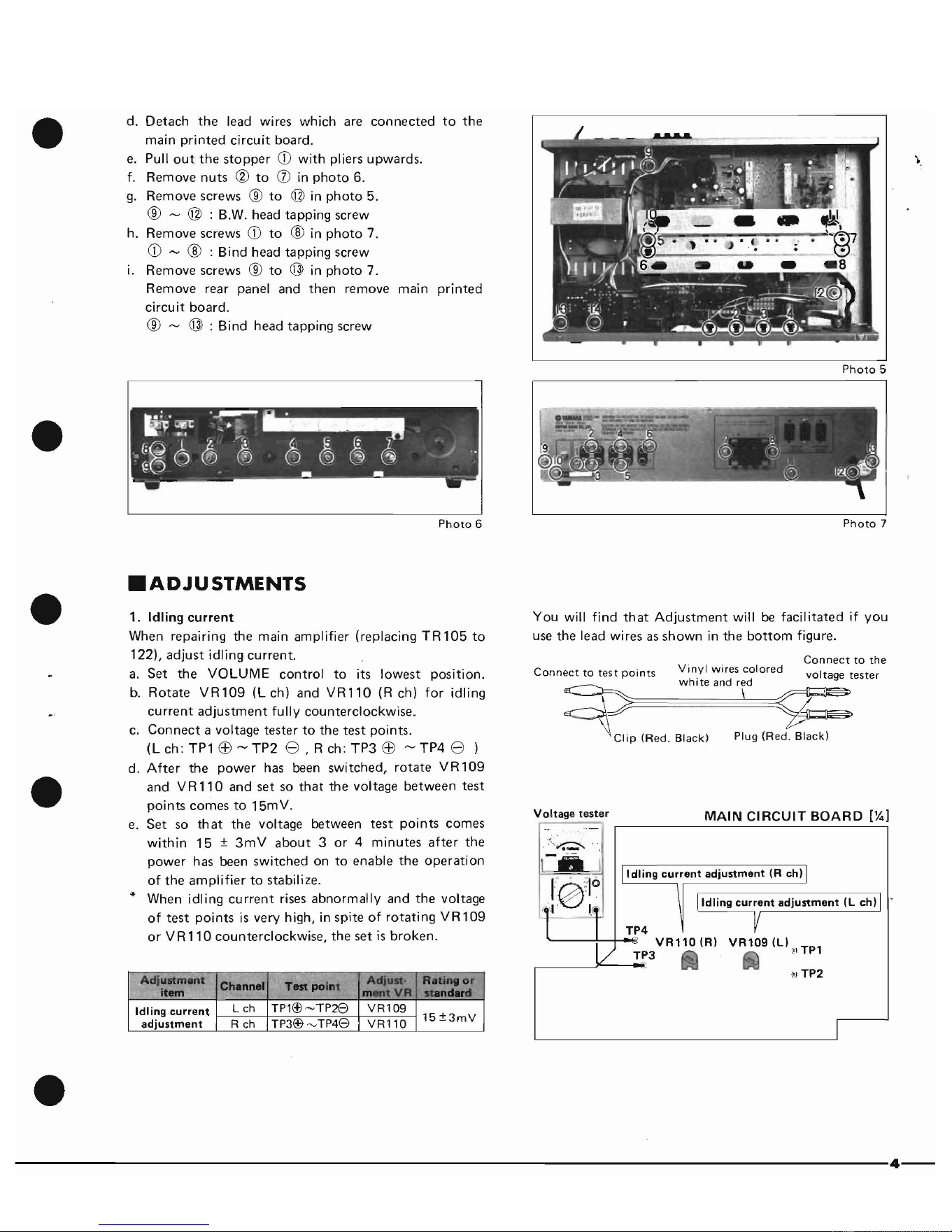
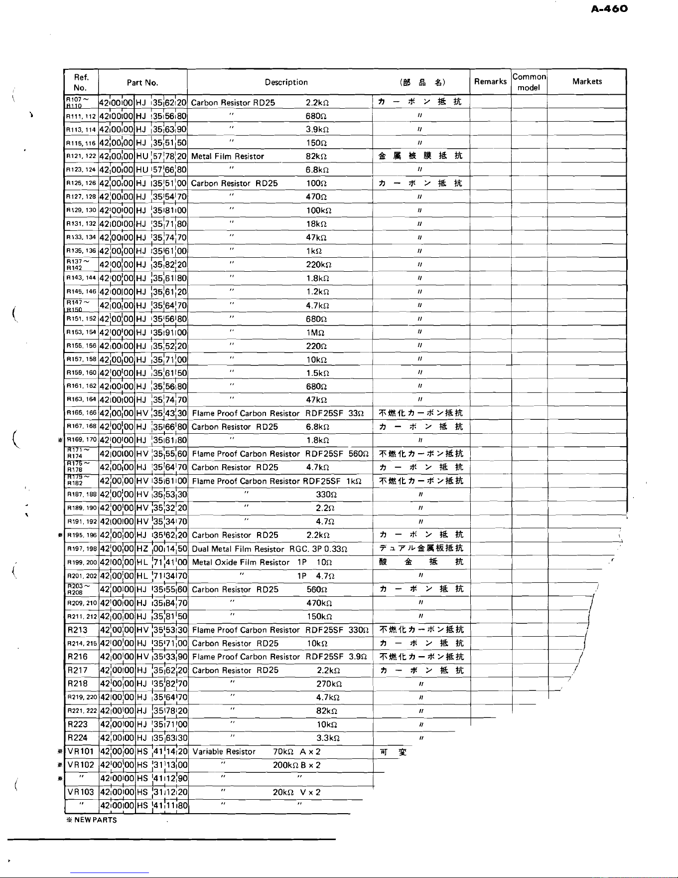
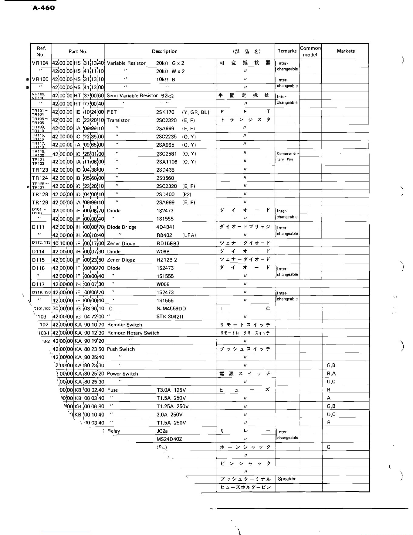
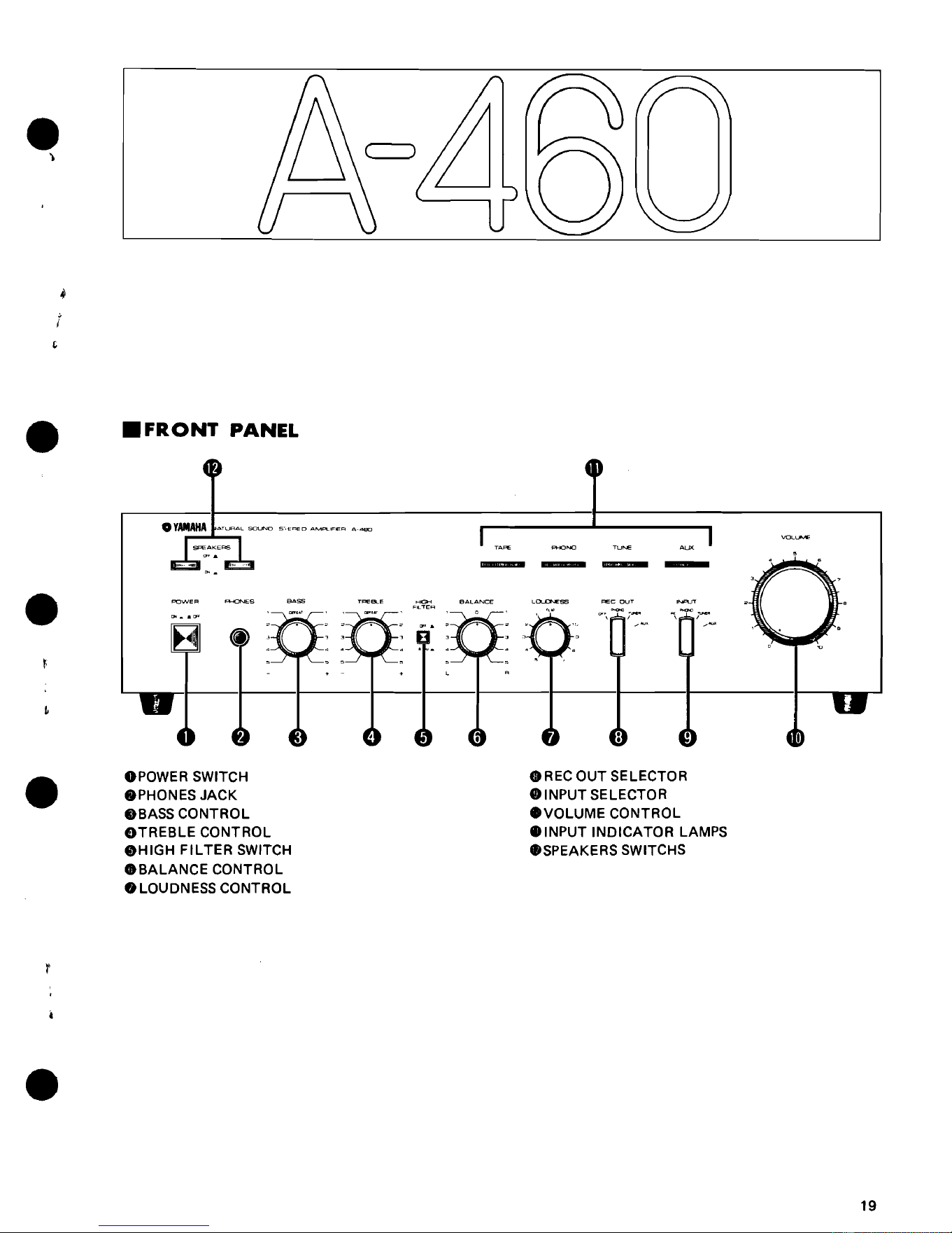
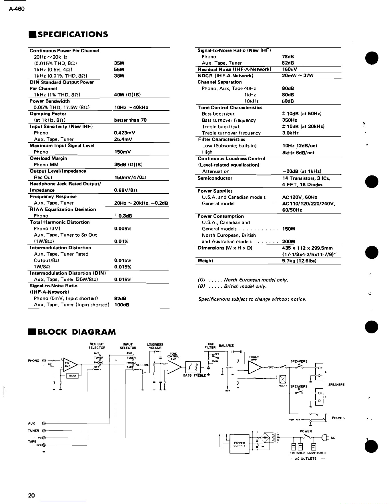
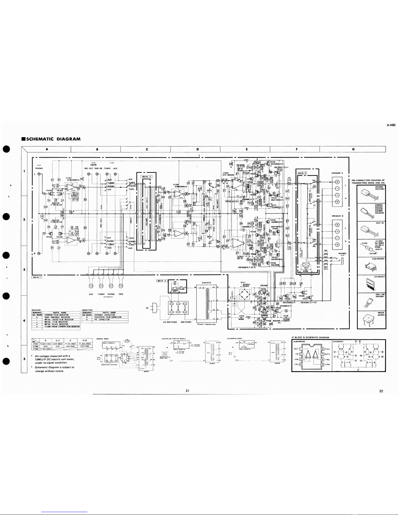
.ADJUSTMENTS
1.
Idling
current
You
will find
that
Adjustment
will be
facilitated
if
you
When repairing
the
main
amplifier
(replacing
TR105
to use
the
lead
wires as
shown
in
the
bottom
figure.
122),
adjust
idling
current.
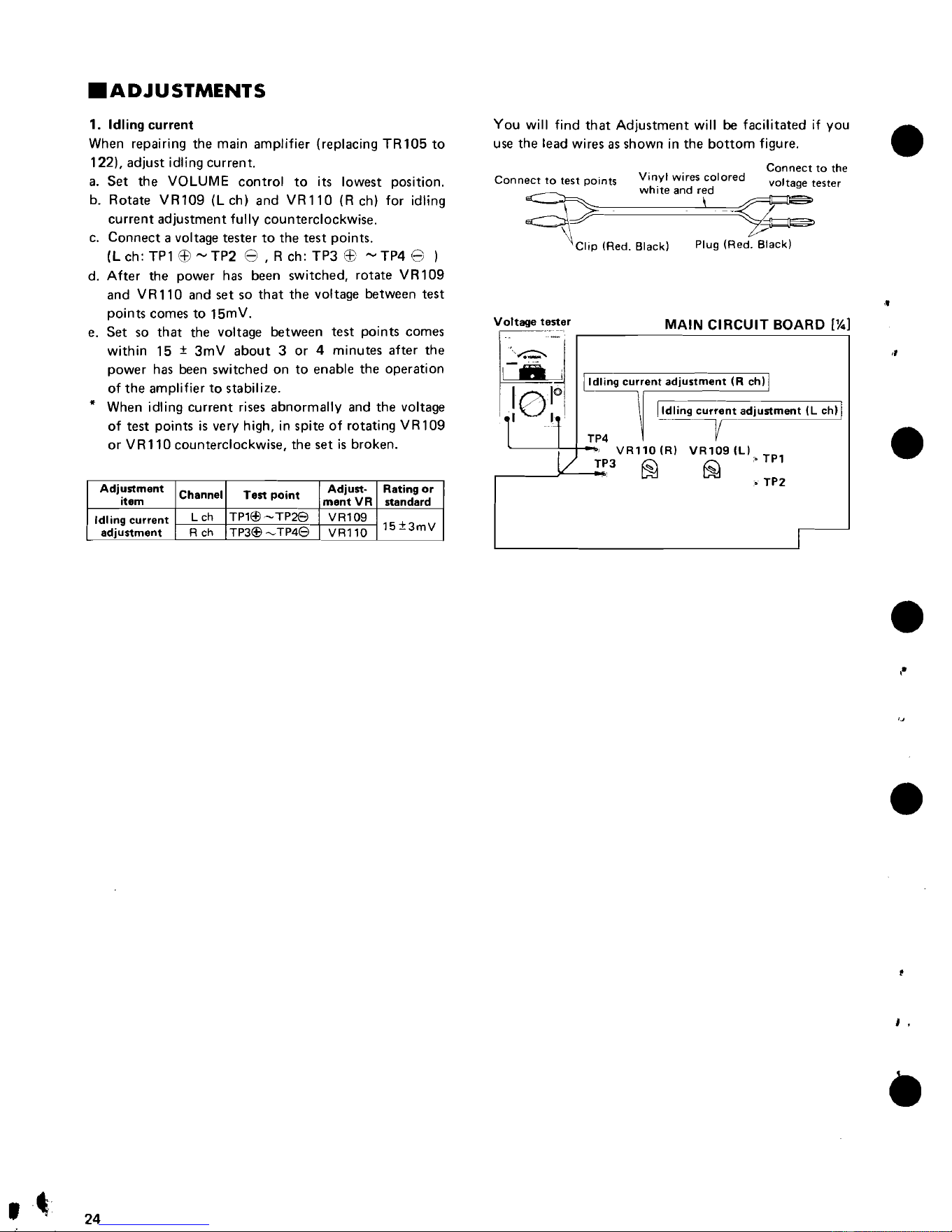
Connect
to the
•
a.
Set
the
VOLUME
control
to
its
lowest
position.
Connect
to
test
points
Vinyl wires
colored
voltage
tester
~
white
and red
b.
Rotate
VR109
(Lch)
and
VR110
(Rch)
for
idling
\ \
~
current
adjustment
fully
counterclockwise.
c.
Connect
a voltage
tester
to
the
test
points.
~c"p
(Red. Black) Plug
(Red.
~
(L ch: TP1
EEl
'""
TP2
8 , R ch:
TP3
EB
'""
TP4
8 )
d.
After
the
power
has
been
switched,
rotate
VR1
09
and
VR 110
and
set
so
that
the
voltage
between
test
points
comes
to
15mV.
e.
Set
so
that
the
voltage
between
test
points
comes
within
15 ±
3mV
about
3
or
4
minutes
after
the
power
has been
switched
on to
enable
the
operation
of
the
amplifier to stabil ize.
* When idling
current
rises
abnormally
and
the
voltage
of
test
points
is very high, in
spite
of
rotating
VR109
or
VR110
counterclockwise,
the
set
is
broken.
i~
[idling
current
adjustment
(R eh] I
\ Iidling
current
adjustment
(L ch] I
'1"
I
TP4
~_·-v
1
VRll0(R)
VR109(LlcoTPl
:/
TP3
~
@
o
TP2
I
Voltage
tester
MAIN
CIRCUIT
BOARD
[~l
,e
r
•
Adjustment
item
Channel
Test
point
Adjust·
ment
VR
Rating
or
standard
Idling
current
L ch
TP1Ef!
-
TP28
VR109
l5±3mV
adjustment
R ch TP3Efi
~
TP48
VRll0
•
,.
'J
•
•
,,
.
'~".
24
Downloaded from www.ManualsFile.com manuals search engine