1
IN638402AV 3/16
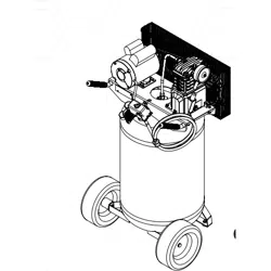
PORTABLE
AIR
COMPRESSOR
ITEM #0268707
MODEL #VT638902
Français p. 29
Español p. 59
KOBALT
®
and the K Design
®
are registered
trademarks of LF, LLC. All Rights Reserved.
Questions, problems, missing parts? Before returning to your retailer, call our customer
service department at 1-888-3KOBALT (1-888-356-2258), 8 a.m. - 8 p.m., EST,
Monday - Friday.
ATTACH YOUR RECEIPT HERE
Serial Number Purchase Date
AB16191
kobalttools.com
2
Safety Guidelines .......................................................................................................................... 3
Safety Information ......................................................................................................................... 3
Package Contents ......................................................................................................................... 6
Hardware Contents........................................................................................................................ 6
Preparation .................................................................................................................................... 7
Assembly Instructions.................................................................................................................... 8
Operating Instructions ................................................................................................................... 13
Care and Maintenance .................................................................................................................. 15
Troubleshooting ............................................................................................................................. 16
Warranty ........................................................................................................................................ 20
Exploded Drawings........................................................................................................................ 22
TABLE OF CONTENTS
PRODUCT SPECIFICATIONS
COMPONENT SPECIFICATIONS
Model VT638902
HP 2
Number of Cylinders 2
Air Delivery @ 90 PSI 5.5 CFM
Voltage 120 Volts* / 15 Amps
240 Volts / 7.5 Amps
* Factory wiring
Max Pressure 155 PSI
COMPONENT SPECIFICATIONS
Oil Capacity approx. 8.5 oz.
Tank Outlet Size 1/4 NPT
Depth 23 in.
Width 24 in.
Height 46 in.
Weight 178 lbs.
kobalttools.com
3
Please read and understand this entire manual before attempting to assemble, operate or install
the product. If you have any questions regarding the product, please call customer service at
1-888-3KOBALT (1-888-356-2258), 8:00 am - 8:00 pm, EST, Monday - Friday.
This manual contains information that is very important to know and understand. This information
is provided for SAFETY and to PREVENT EQUIPMENT PROBLEMS. To help recognize this
information, observe the following symbols.
SAFETY GUIDELINES
CALIFORNIA PROPOSITION 65
CAUTION
Caution indicates a potentially hazardous
situation which, if not avoided, MAY result in
minor or moderate injury.
NOTICE
Notice indicates important information,
that if not followed, may cause damage to
equipment.
DANGER
Danger indicates an imminently hazardous
situation which, if not avoided, WILL result in
death or serious injury.
WARNING
Warning indicates a potentially hazardous
situation which, if not avoided, COULD result
in death or serious injury.
SAFETY INFORMATION
WARNING
Handle with Care. This product or its power
cord may contain chemicals known to the
State of California to cause cancer and birth
defects or other reproductive harm. Wash
hands after handling.
WARNING
Wear eye and mask protection.
You can create dust when you cut,
sand, drill or grind materials such
as wood, paint, metal, concrete,
cement, or other masonry. This
dust often contains chemicals
known to cause cancer, birth
defects, or other reproductive
harm. Wear protective gear.
GENERAL SAFETY
Since the air compressor and other components (material pump, spray guns, filters, lubricators,
hoses, etc.) used, make up a high pressure pumping system, the following safety precautions must be
observed at all times:
1. Read all manuals included with this product carefully. Be thoroughly familiar with the controls
and the proper use of the equipment.
2. Follow all local electrical and safety codes as well as in the United States, the National Electrical
Codes (NEC) and Occupational Safety and Health Act (OSHA).
3. Only persons well acquainted with these rules of safe operation should be allowed to use the
compressor.
4. Keep visitors away and NEVER allow children in the work area.
5. Wear safety glasses and use hearing protection when operating the unit.
kobalttools.com
4
GENERAL SAFETY (Continued)
6. Do not stand on or use the unit as a handhold.
7. Before each use, inspect compressed air system and electrical components for signs of damage,
deterioration, weakness or leakage. Repair or replace defective items before using.
8. Check all fasteners at frequent intervals for proper tightness.
9. Do not wear loose clothing or jewelry that will get caught in the moving parts of the unit.
10. Keep fingers away from a running compressor; fast moving and hot parts will cause injury and/or
burns.
11. If the equipment should start to vibrate abnormally, STOP the motor and check immediately for
the cause. Vibration is generally a warning of trouble.
12. To reduce fire hazard, keep motor exterior free of oil, solvent, or excessive grease.
13. Never attempt to adjust ASME safety valve. Keep safety valve free from paint and other
accumulations.
14. Tanks rust from moisture build-up, which weakens the tank. Make sure to drain tank daily and
inspect periodically for unsafe conditions such as rust formation and corrosion.
15. Fast moving air will stir up dust and debris which may be harmful. Release air slowly when
draining moisture or depressurizing the compressor system.
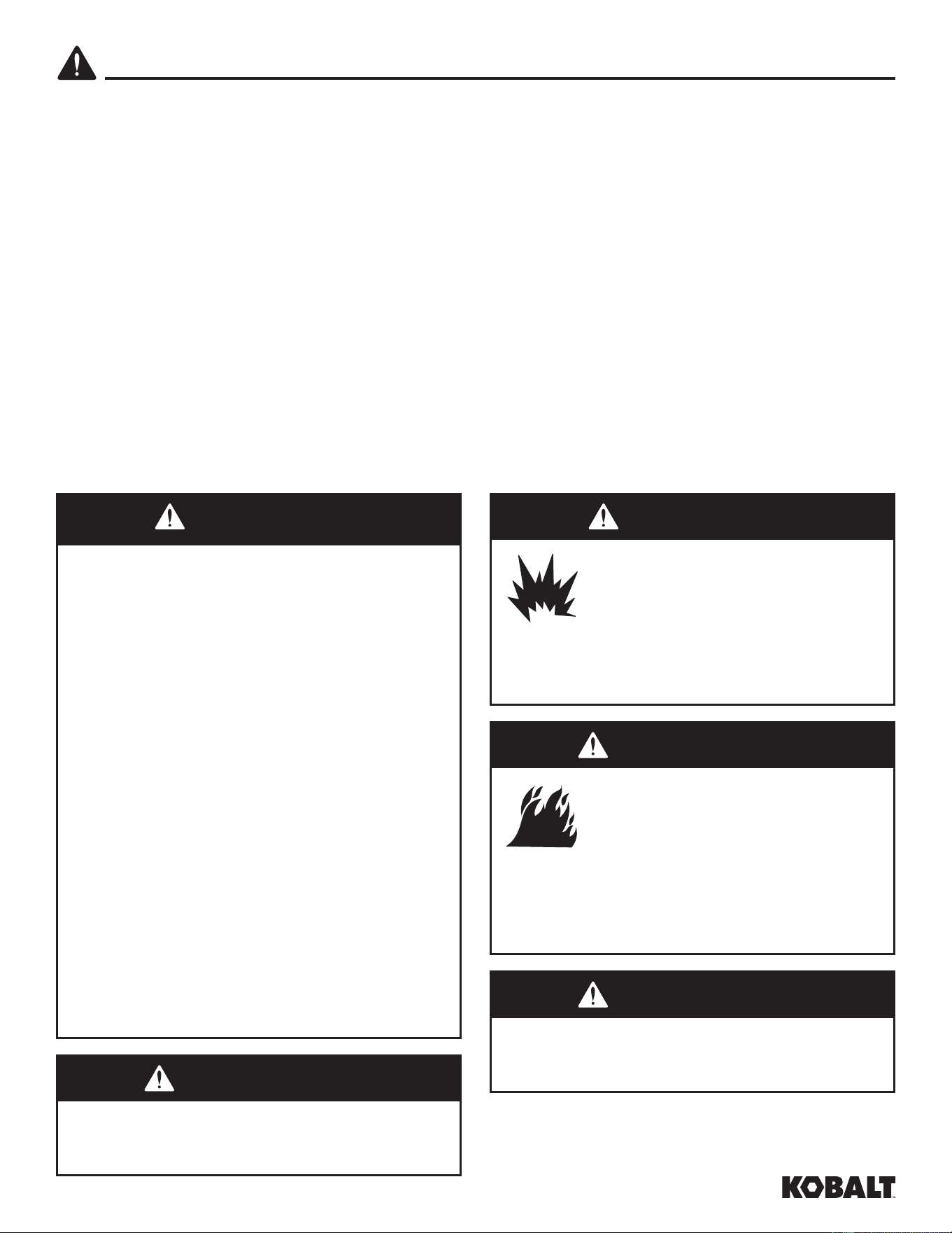
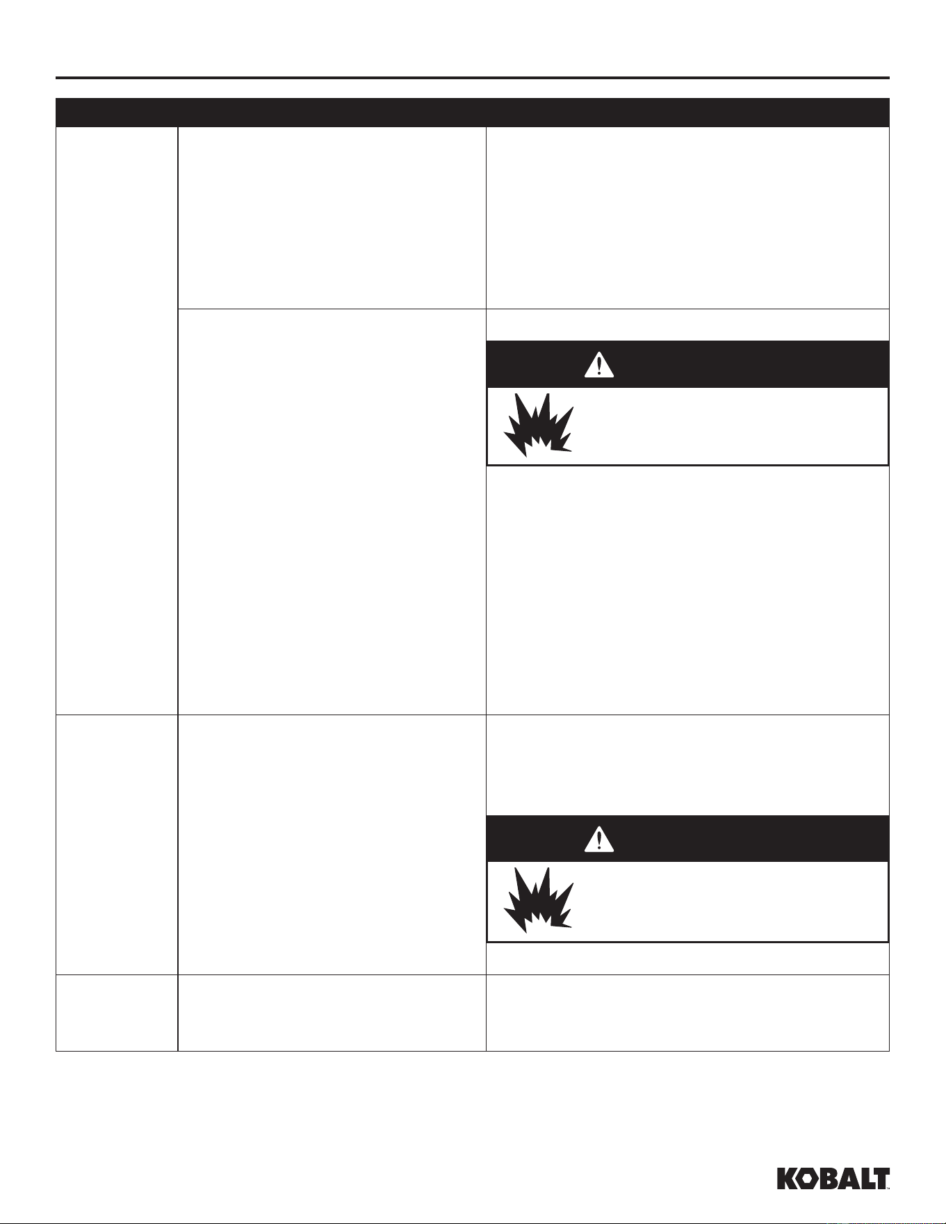
SAFETY INFORMATION
Risk of Explosion. Never attempt
to repair or modify a tank! Welding,
drilling or any other modifi cation
will weaken the tank resulting in
damage from rupture or explosion.
Always replace worn, cracked or
damaged tanks.
DANGER
WARNING
Risk of Fire. Motors, electrical
equipment and controls can cause
electrical arcs that will ignite a
fl ammable gas or vapor. Never
operate or repair in or near a
fl ammable gas or vapor. Never
store fl ammable liquids or gases in
the vicinity of the compressor.
DANGER
Risk of Personal Injury. This compressor/
pump is NOT equipped and should NOT be
used “as is” to supply breathing quality air. For
any application of air for human consumption,
you must fit the air compressor/pump with
suitable in-line safety and alarm equipment.
This additional equipment is necessary
to properly filter and purify the air to meet
minimal specifications for Grade D breathing
as described in Compressed Gas Association
Commodity Specification G 7.1, OSHA 29
CFR 1910. 134, and/or Canadian Standards
Associations (CSA).
DISCLAIMER OF WARRANTIES
In the event the compressor is used for the
purpose of breathing air application and
proper in-line safety and alarm equipment is
not simultaneously used, existing warranties
are void, and the Manufacturer disclaims any
liability whatsoever for any loss, personal injury
or damage.
WARNING
Risk of Explosion. Never use plastic (PVC)
pipe for compressed air. Serious injury or
death could result.
WARNING
Risk of Personal Injury and/or Equipment
Damage. Never install a shut-off valve
between the compressor pump and the tank.
kobalttools.com
5
SAFETY INFORMATION
WARNING
Risk of Fire. Do not spray
fl ammable materials in vicinity
of open fl ame or near ignition
sources including the compressor
unit.
SPRAYING PRECAUTIONS
1. Do not smoke when spraying paint, insecticides, or other flammable substances.
2. Use a face mask/respirator when spraying and spray in a well-ventilated area to prevent health
and fire hazards.
3. Do not direct paint or other sprayed material at the compressor. Locate compressor as far away
from the spraying area as possible to minimize overspray accumulation on the compressor.
4. When spraying or cleaning with solvents or toxic chemicals, follow the instructions provided by
the chemical manufacturer.
CAUTION
Do Not Overpressure. See compressor
specifi cation decal for maximum operating
pressure. Do not operate with pressure switch
or safety valves set higher than the maximum
operating pressure.
NOTICE
Unit Care and Maintenance. Drain liquid from
tank daily.
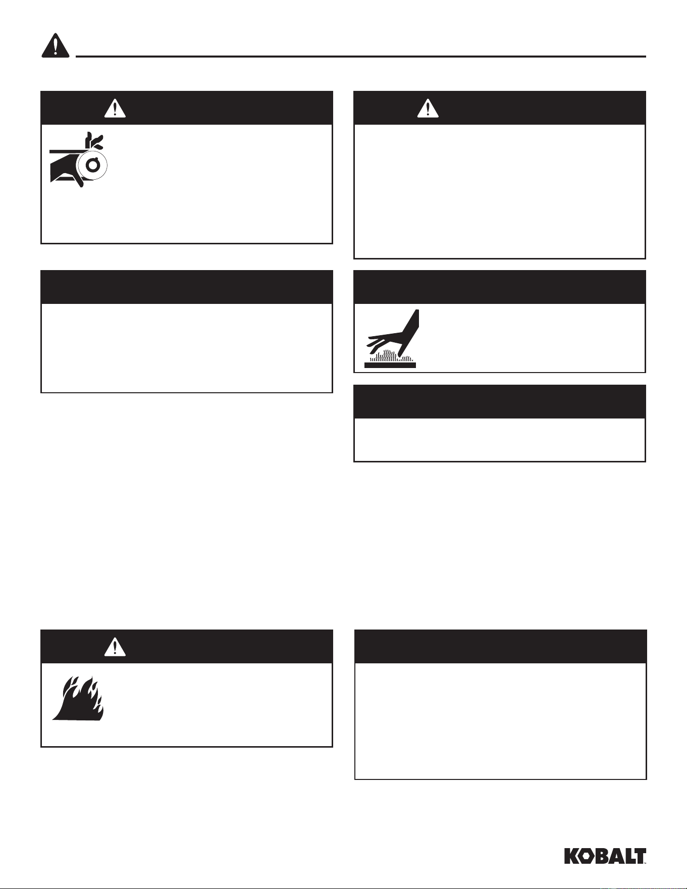
GENERAL SAFETY (Continued)
Risk of Personal Injury.
Compressor parts may be hot
even if the unit is stopped.
CAUTION
WARNING
Risk of Personal Injury. Never
operate compressor without a
beltguard. This unit can start
automatically without warning.
Personal injury or property
damage could occur from contact
with moving parts.
WARNING
Risk of Explosion. An ASME code safety
relief valve with a setting no higher than
the maximum allowable working pressure
(MAWP) MUST be installed in the tank for
this compressor. The ASME safety valve must
have suffi cient fl ow and pressure ratings to
protect the pressurized components from
bursting.
NOTICE
The DANGER, WARNING, CAUTION,
and NOTICE notifications and instructions
in this manual cannot cover all possible
conditions and situations that may occur.
It must be understood by the operator that
caution is a factor which cannot be built
into this product, but must be supplied by
the operator.
kobalttools.com
6
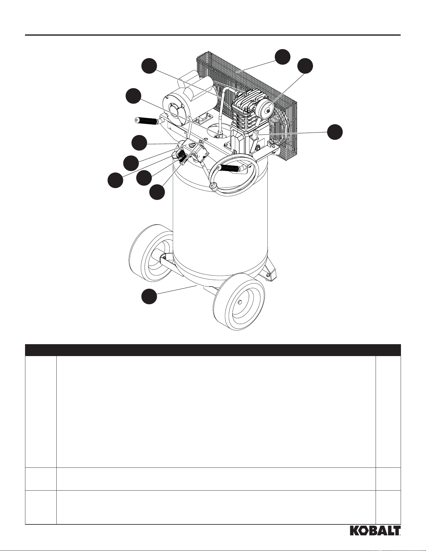
PACKAGE CONTENTS
PART DESCRIPTION QTY.
A Pressure Switch - AUTO/OFF Switch - In the AUTO position, the compressor
shuts off automatically when tank pressure reaches the maximum preset pressure.
After air is used from the tank and drops to a preset low level, the pressure switch
automatically turns the motor back on. In the OFF position, the compressor will not
operate. This switch should be in the OFF position when connecting or disconnecting
the power from the unit.
When the pressure switch turns the motor off you will hear air leaking out of the
pressure switch unloader valve for a short time. This releases the air pressure from
the discharge tube and allows the compressor to restart easier.
1
B ASME Safety Valve - This valve automatically releases air if the tank pressure
exceeds the preset maximum.
1
C Discharge tube - This tube carries compressed air from the pump to the check valve.
This tube becomes very hot during use. To avoid the risk of severe burns, never touch
the discharge tube.
1
A
B
C
D
E
F
G
H
I
J
K
kobalttools.com
7
PACKAGE CONTENTS
WARNING
Risk of Personal Injury. Do not operate unit
if damaged during shipping, handling or use.
Damage may result in bursting and cause
injury or property damage.
Before beginning installation and/or assembly of product, make sure all parts are present. Compare
parts with package contents list and hardware contents list. If any part is missing or damaged, do not
attempt to assemble or use the product.
PREPARATION
PART DESCRIPTION QTY.
D Check valve - One-way valve that allows air to enter the tank, but prevents air in the
tank from flowing back into the compressor pump.
1
E Belt Guard - Covers the belt, motor pulley and flywheel. 1
F Tank Drain Valve - This valve is located on the bottom of the tank. Use this valve to
drain moisture from the tank daily to reduce the risk of corrosion.
1
G Tank Pressure Gauge - Indicates amount of air pressure stored in tank. 1
H Hose Pressure Gauge - Indicates amount of air pressure in hose used to operate
tools. This pressure is increased or decreased by the regulator.
1
I Regulator - The regulator controls the amount of air pressure released at the hose
outlet.
1
J Air Filter - Keeps debris and particulates out of the air flowing into the compressor. 1
K Breather - Vent for crankcase. 1
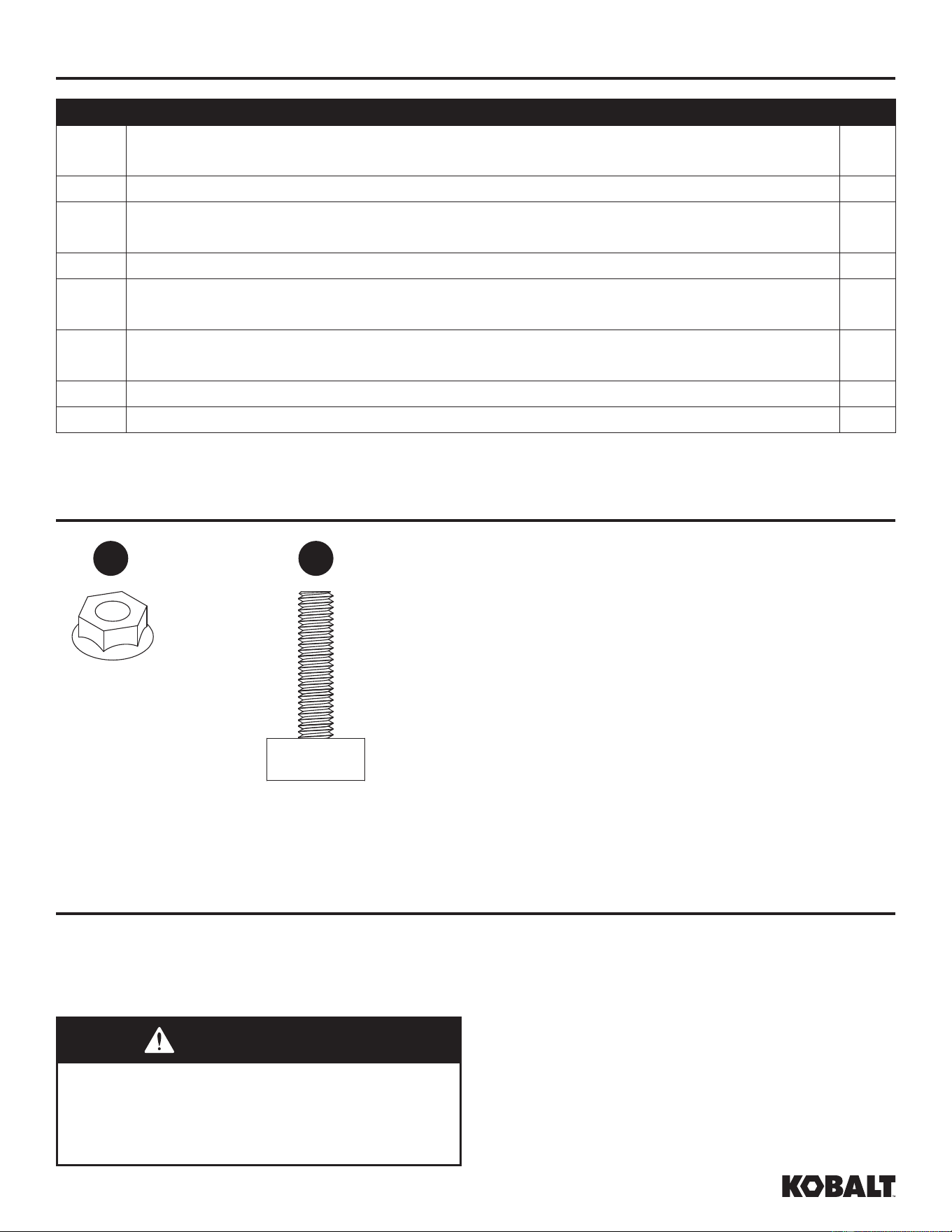
HARDWARE CONTENTS (shown actual size)
AA BB
5/16 in. x
18 Spinlock Nut
Qty. 2
Rubber Foot
Qty. 2
kobalttools.com
8
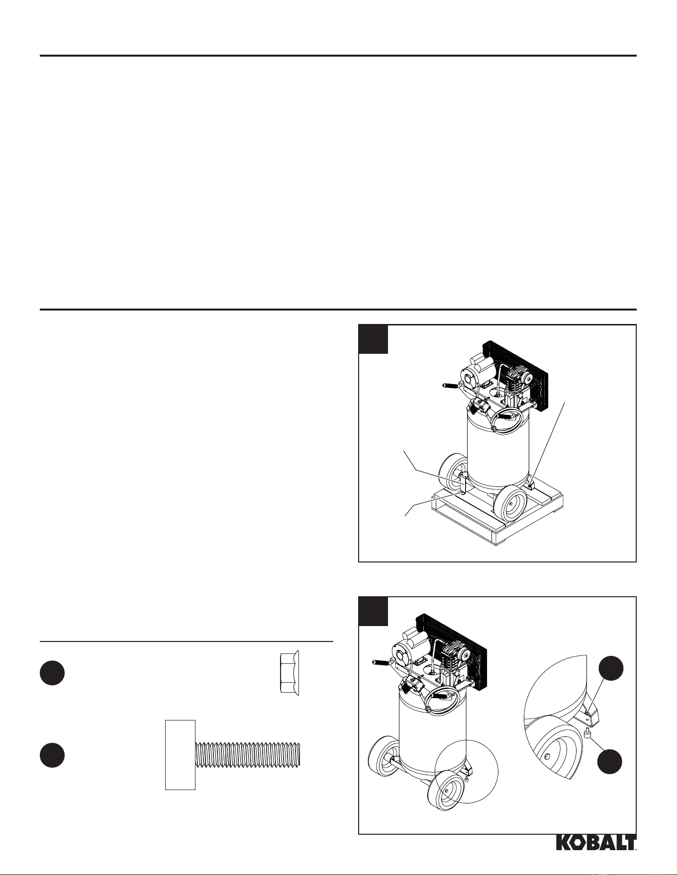
ASSEMBLY INSTRUCTIONS
1. Unbolt the unit from the shipping skid. Use a
ratchet with a 9/16 in. socket. Remove the unit
from the skid. Discard shipping hardware once
removed.
2. Install rubber feet with nuts and washers.
Hardware Used
Nut
AA
x2
PREPARATION
Estimated Installation and Assembly Time: 20 minutes
Tools Required for Installation and Assembly (not included): Safety Glasses; Work Gloves; 9/16 in.
Socket and Ratchet; Adjustable Wrench
ADDITIONAL PARTS REQUIRED FOR USE [not included]:
1. Air Hose
2. Pipe Thread Sealant
BB
Rubber Foot x2
1
Shipping
Bolt
Shipping
Bracket
Shipping
Bolt
2
AA
BB
kobalttools.com
9
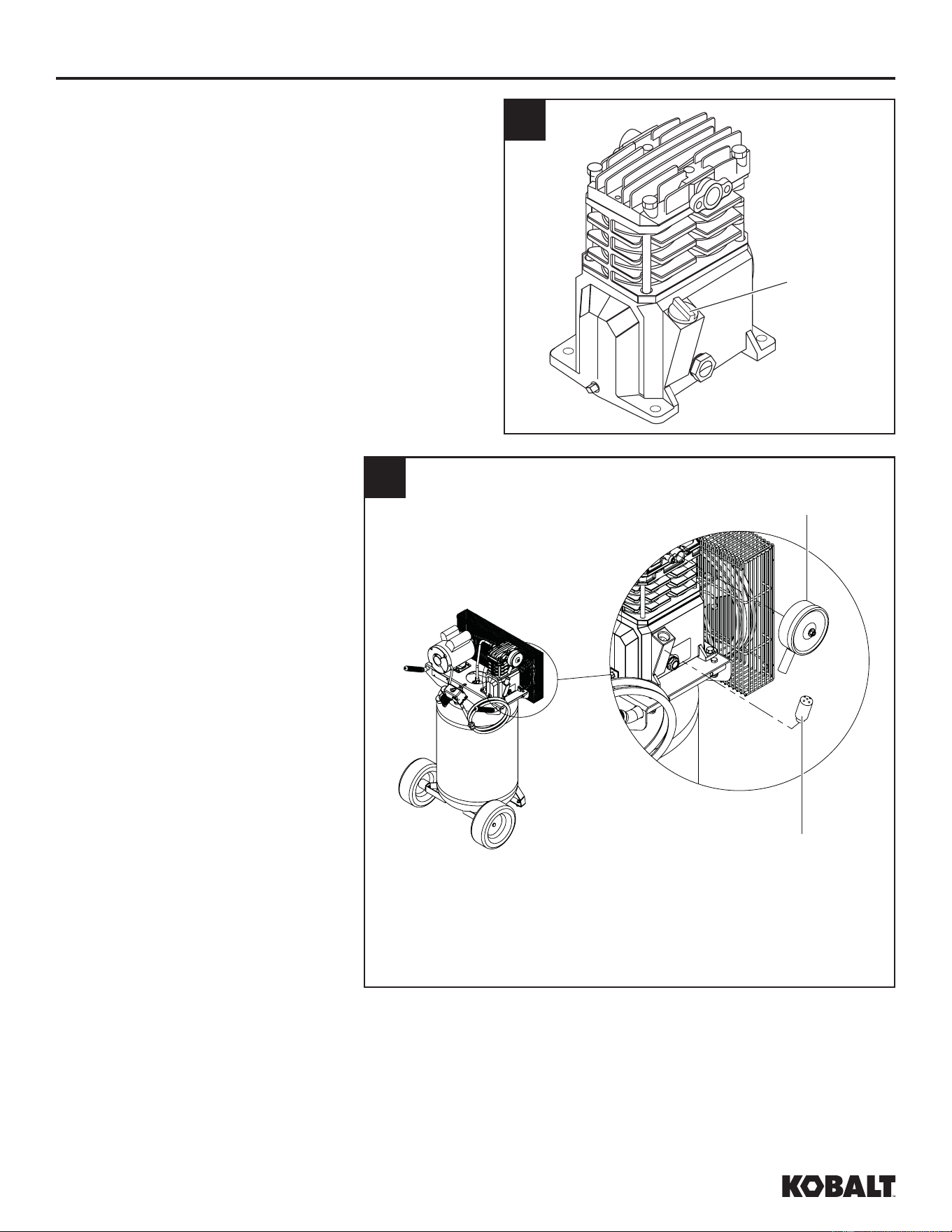
ASSEMBLY INSTRUCTIONS
3. Remove cap from pump.
4. Install breather. Install air
fi lter.
3
Cap
kobalttools.com
4
Air Filter
Breather
10
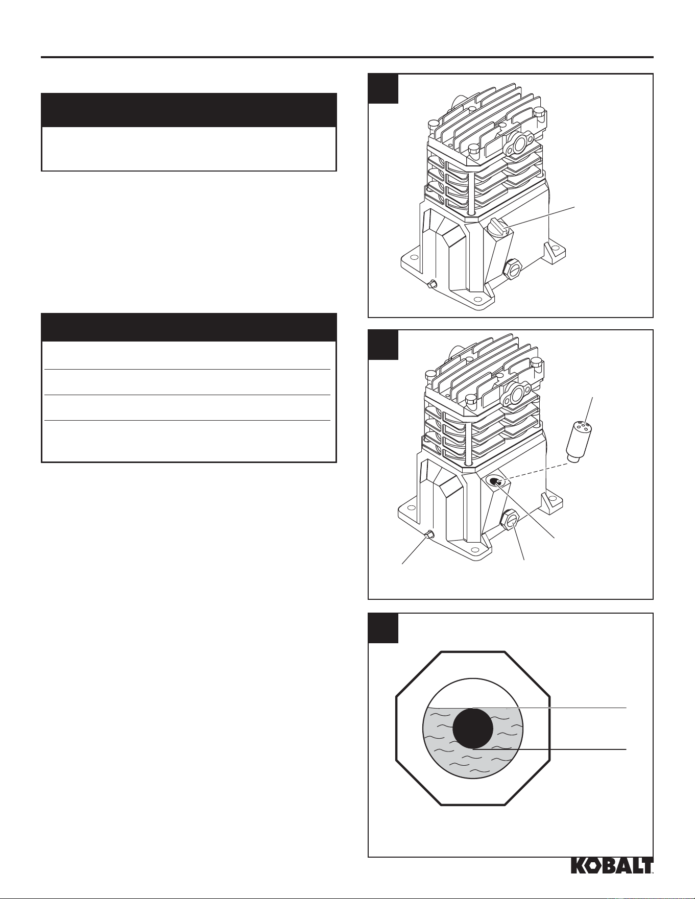
ASSEMBLY INSTRUCTIONS
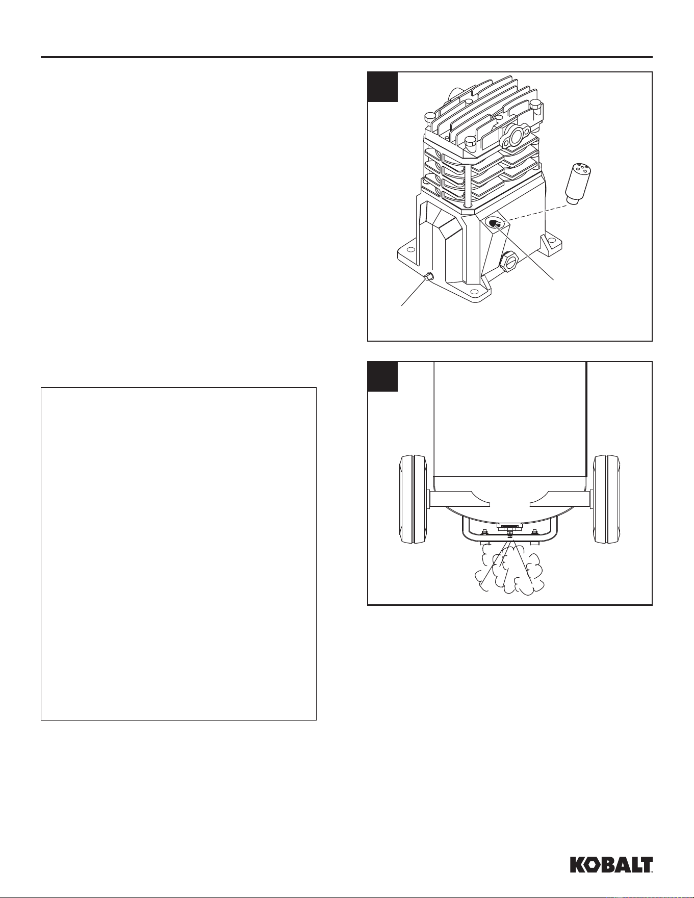
LUBRICATION
CAUTION
Inspect Before Use. Check for proper oil level
before operating!
Remove cap from oil fill opening. See Figure
1. Install breather (found in parts bag with this
manual). See Figure 2. Check oil level; some
models are shipped with oil in the pump. See
specification label on compressor pump for the
proper oil capacity and oil type.
OIL INFORMATION
Kobalt Air Compressor Oil SKU 221008
Kobalt Synthetic Blend Oil SKU 221009
Mobil 1
®
synthetic 10W30
Oil Capacity
approximately 8.5
ounces
Do not use regular automotive oil. Additives
in regular motor oil can cause valve deposits
and reduce pump life. For maximum pump
life, drain and replace oil after the first fifty (50)
hours of operation and then follow the regular
maintenance schedule outlined later
in the manual.
This pump has an oil sight glass as shown
in Figure 2. Oil level can be monitored and
maintained as shown in Figure 3.
1
Cap
2
Breather
Oil Fill Area
Oil Drain
Plug
Sight
Glass
3
Sight Glass
Full
Low
kobalttools.com
11
ASSEMBLY INSTRUCTIONS
ELECTRICAL INFORMATION
Risk of Shock. Improperly
grounded motors are shock
hazards. Make sure all the
equipment is properly grounded.
DANGER WARNING
Risk of Personal Injury or Damage to
Personal Property. Overheating, short
circuiting and fi re damage will result from
inadequate wiring.
NOTICE
Unit care and maintenance. Damage to the
motor from improper electrical voltage or
connection will void the warranty.
WARNING
Risk of Explosion. Disconnect,
tag and lock out power source,
then release all pressure from the
system before attempting to install,
service, relocate or perform any
maintenance.
Risk of Shock. Improper
installation of the grounding plug
is able to result in a risk of electric
shock. When repair or replacement
of the cord or plug is required, do
not connect the grounding wire
to either fl at blade terminal. The
wire with insulation having an
outer surface that is green with
or without yellow stripes is the
grounding wire.
WARNING
Do not use an extension cord, use a longer air hose.
The 120 volt, 15 amp units can be operated on a 120 volt, 15 amp circuit under the following
conditions:
1. No other electrical appliances or lights are connected to the same branch circuit.
2. Voltage is 120 Volts.
3. Circuit is equipped with a 15 amp circuit breaker or a 15 amp slow blow fuse type T (For Canada
use Type D).
4. The length of copper wire between the outlet and circuit breaker is not longer than 40 ft. of
14 AWG or 70 ft. of 12 AWG.
kobalttools.com
12
ASSEMBLY INSTRUCTIONS
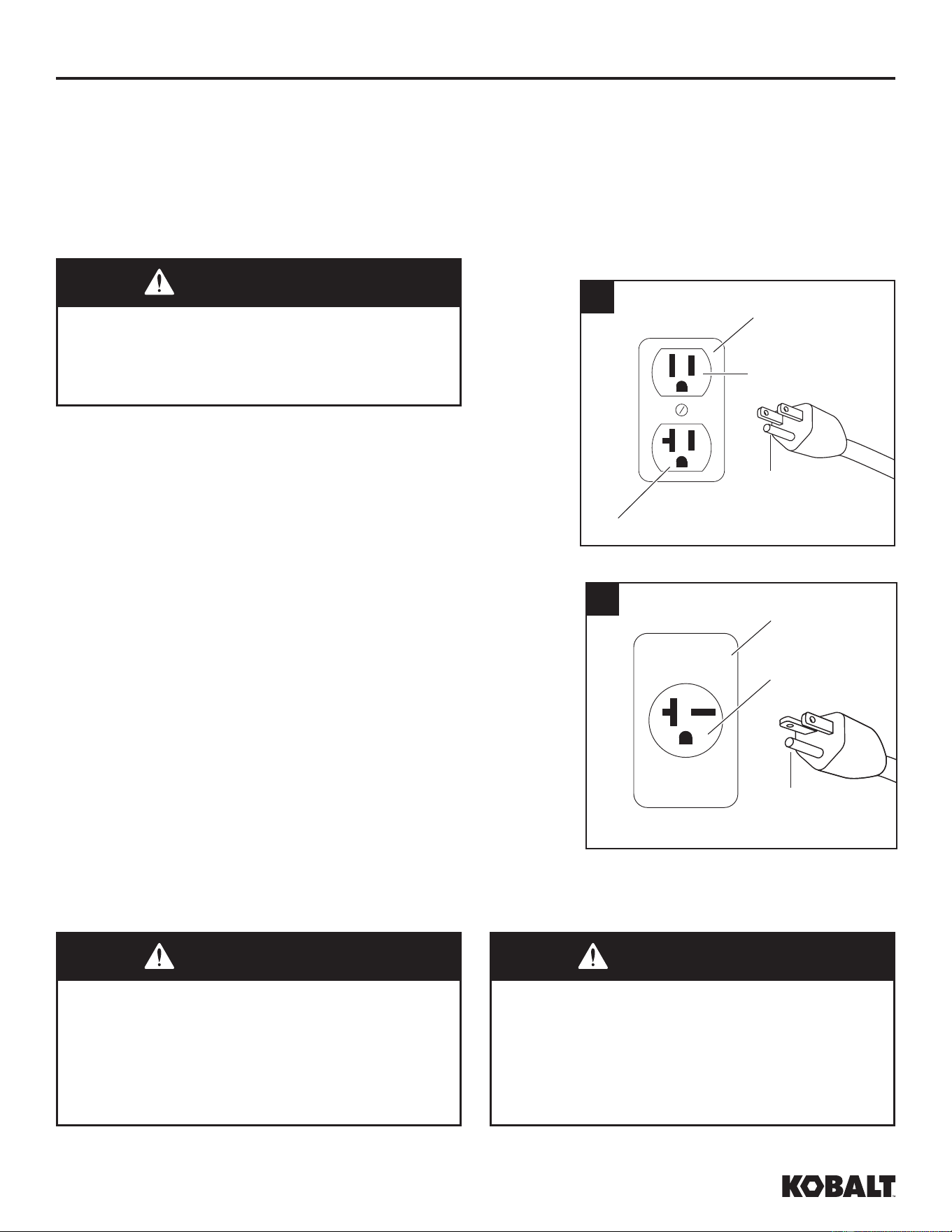
This product comes from the factory ready for use
on a nominal 120 volt circuit and has a grounding
plug similar to the plug illustrated in Figure 1. If
the listed conditions cannot be met or if nuisance
tripping of the current protection device occurs, it
may be possible to operate the compressor from
a 120 volt 20 amp circuit. See Figure 1.
Check motor data plate for 240 volt compatibility.
A 240 volt unit must be operated on a 240 volt
circuit. The cord must only plug into a 240 volt
grounded outlet and may require a new cord and
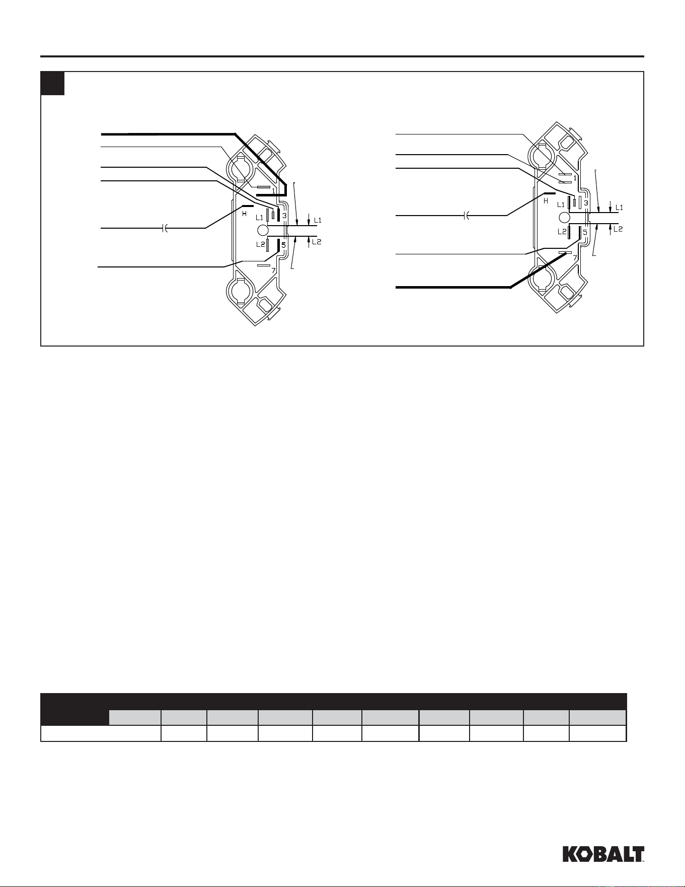
plug. See Figure 2. This product may be modified
to operate at 240V. To do so, a 240V power cord
needs to be purchased and installed on the unit
and wired into the pressure switch just like the
120V cord. The panel on the back of the motor
needs to be opened and the flag terminals need
to be moved so that the brown wire that is on
terminal #1 is on terminal #7 and the white wire
that is on terminal #3 needs to be moved to
terminal #1 (where the brown wire was originally).
See Figure 3.
GROUNDING
This product must be grounded. In the event of an electrical short circuit, grounding reduces the risk of
electric shock by providing an escape wire for the electric current. This product is equipped with a cord
having a grounding wire with an appropriate grounding plug. The plug must be plugged into an outlet
that is properly installed and grounded in accordance with all local codes and ordinances. Do not use
grounding adapter.
1
Ground
Pin
Grounded
Outlet
Outlet - 120V / 15A
Outlet - 120V / 20A
2
Grounded
Outlet
Ground
Pin
Outlet - 240V
Risk of electric shock. Improper use of grounding
plug can result in a risk of electrical shock. Plug
must be plugged into an outlet that is properly
installed and grounded in accordance with local
codes and ordinances by a qualified electrician.
WARNING
All wiring and electrical connections should be
performed by a qualifi ed electrician. Installation
must be in accordance with local codes and
national electrical codes.
If not properly grounded, this tool can
cause an electrical shock, particularly when used in
damp locations, in proximity of plumbing, outdoors.
WARNING WARNING
Installation of grounding plug can result in electric
shock. When repair or replacement of the cord or plug
is required, do not connect the grounding wire to either
flat blade terminal. The wire with insulation having an
outer surface that is green with or without yellow stripes
is the grounding wire. Never connect green (or green
and yellow) wire to a live terminal.
kobalttools.com
13
Use only a 3-wire extension cord that has a 3-blade grounding plug and a 3-slot receptacle that
accepts the plug on the product. Make sure your extension cord is not damaged. When using an
extension cord, be sure to use one heavy enough to carry the current your product draws. For lengths
less than 25 ft. 16-3 AWG extension cords shall be used. An undersized cord results in a drop in
the voltage and loss of power and overheating. (NOTICE: Table below shows the correct size to
use depending on cord length. When in doubt, use the next heavier gauge. The smaller the gauge
number, the heavier the cord.)
Use of an extension cord may cause excess heat to motor. This could lead to tripped breaker (at
electrical panel) or tripped thermal overload (on compressor motor). If this occurs, eliminate extension
cord and plug compressor directly into electrical outlet. Avoid using extension cords; use longer air
hose(s) instead.
Check with a qualified electrician or serviceman when the grounding instructions are not completely
understood, or when in doubt as to whether the product is properly grounded. Do not modify the plug
provided; if it does not fit the outlet, have the proper outlet installed by a qualified electrician. Only
connect the product to an outlet having the same configuration as the plug. Do not use an adapter with
this product.
Amp Rating
Range
Voltage Cord Length in Feet
120V 25 ft. 50 ft. 100 ft. 150 ft. 200 ft. 250 ft. 300 ft. 400 ft. 500 ft.
14-16 16 12 10 8 6 6 4 4 2
ASSEMBLY INSTRUCTIONS
kobalttools.com
3
[Brown]
[Purple]
[Black]
[Yellow]
[White]
[Orange]
Black
Cord
Lead
White
Cord
Lead
[Brown]
[Black]
Black
Cord
Lead
White
Cord
Lead
[Orange]
[White]
[Yellow]
[Purple]
120V Confi guration 240V Confi guration
14
OPERATING INSTRUCTIONS
1. Check oil level per the Lubrication Section of this
manual.
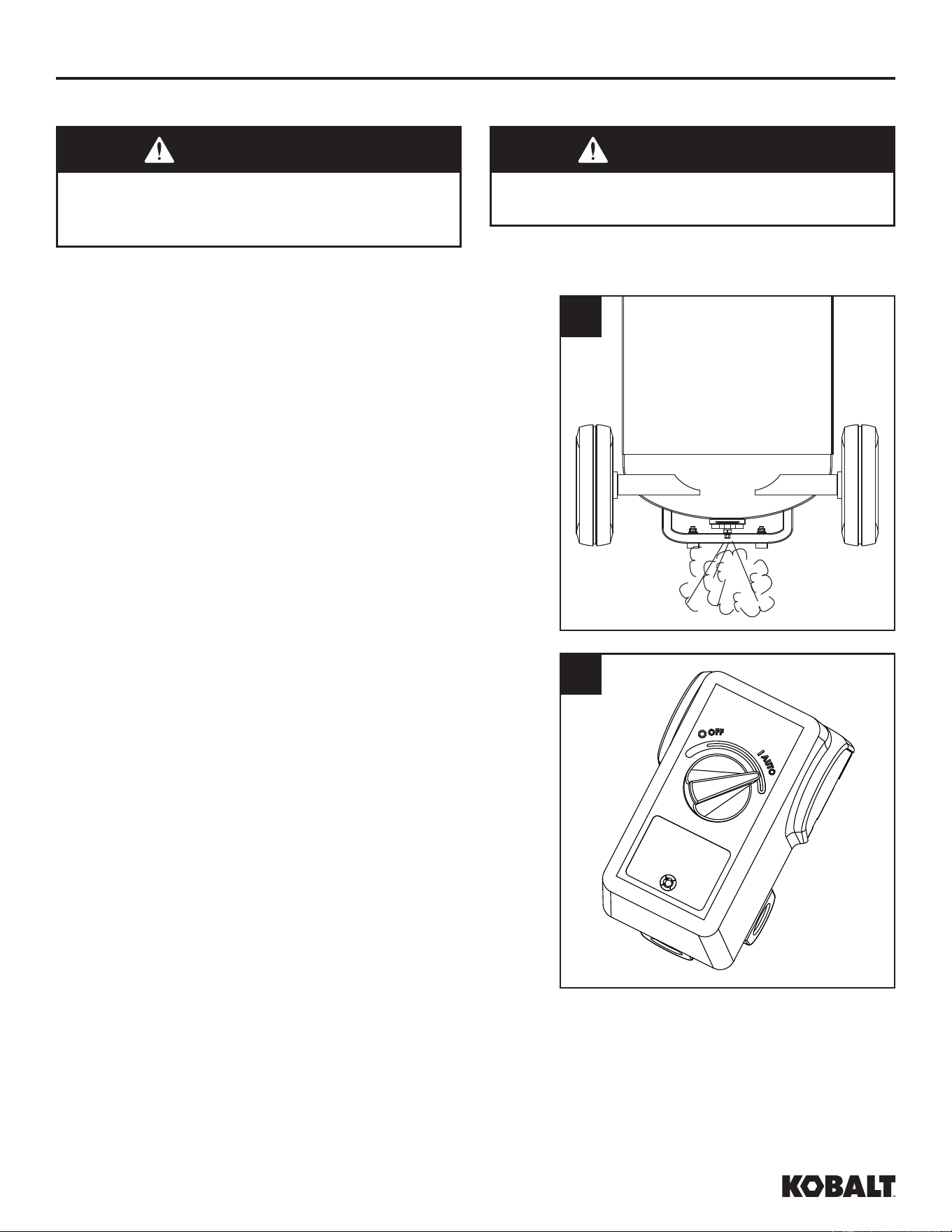
2. Open the bottom tank drain valve (see Figure 1).
Turn outlet valve to open air flow.
3. Plug unit in.
START-UP / BREAK-IN PROCEDURE
WARNING
Risk of Personal Injury. Never disconnect
threaded joints with pressure in tank!
WARNING
Risk of Personal Injury. Do not attach air
tools to open end of the hose until start-up is
completed and the unit checks okay.
1
4. Move pressure switch to the AUTO position to run the
unit (see Figure 2).
5. Run the unit for thirty (30) minutes at zero (0) psi
(under no load) to break in pump parts.
6. Move the pressure switch lever or knob to OFF
and turn tank drain valve to shut off air flow. The
compressor is now ready for use.
7. Change oil after first fifty (50) hours of operation.
Then perform oil changes every three (3) months
or two hundred (200) hours of run time, whichever
comes first.
2
COMPRESSOR USE
It is extremely important to operate the compressor in a clean, well-ventilated area where the
surrounding air temperature will not be more than 100°F. Do not locate the compressor air inlet near
steam, paint spray, sandblast areas or any other source of contamination.
kobalttools.com
15
OPERATING INSTRUCTIONS
In the AUTO position, the compressor pumps air
into the tank. When a shut-off (preset “cut-out”)
pressure is reached, the compressor automatically
shuts off.
If the compressor is left in the AUTO position
and air is depleted from the tank by use of a
tire chuck, tool, etc., the compressor will restart
automatically at its preset “cut-in” pressure. When
a tool is being used continuously, the compressor
will cycle on and off automatically.
In the OFF position, the compressor will not
operate.
NOTICE
Unit care and maintenance. Drain liquid from
tank daily.
ON/OFF CYCLING OF COMPRESSOR
WARNING
Risk of Bursting. Drain tank every day to
prevent corrosion and possible injury due to
tank damage. Do not operate drain with more
than 40 psi in tank or drain valve may be
damaged. Drain tank of moisture daily using
the drain valve in the bottom of the tank.
kobalttools.com
CARE AND MAINTENANCE
WARNING
Risk of Explosion. Disconnect,
tag and lock out power source,
then release all pressure from the
system before attempting to install,
service, relocate or perform any
maintenance.
All repairs should be performed by an authorized service representative.
For efficient operation, perform the following maintenance.
NOTICE
Unit care and maintenance. Drain liquid from
tank daily.
16
CARE AND MAINTENANCE
1. Disconnect power cord plug from power
source receptacle. Clean debris from motor,
flywheel, tank, air lines and pump cooling fins.
2. Maintain proper oil level. Refer to Lubrication
section for details.
3. Change oil.
a. Allow compressor to run and warm up oil.
Disconnect power cord plug from power
source receptacle.
b. Position a pan under pump.
c. Remove oil drain plug (See Figure 1).
Allow oil to collect in pan.
d. Replace drain plug, fill pump to full level
(See Figure 1). See Lubrication section of
this manual.
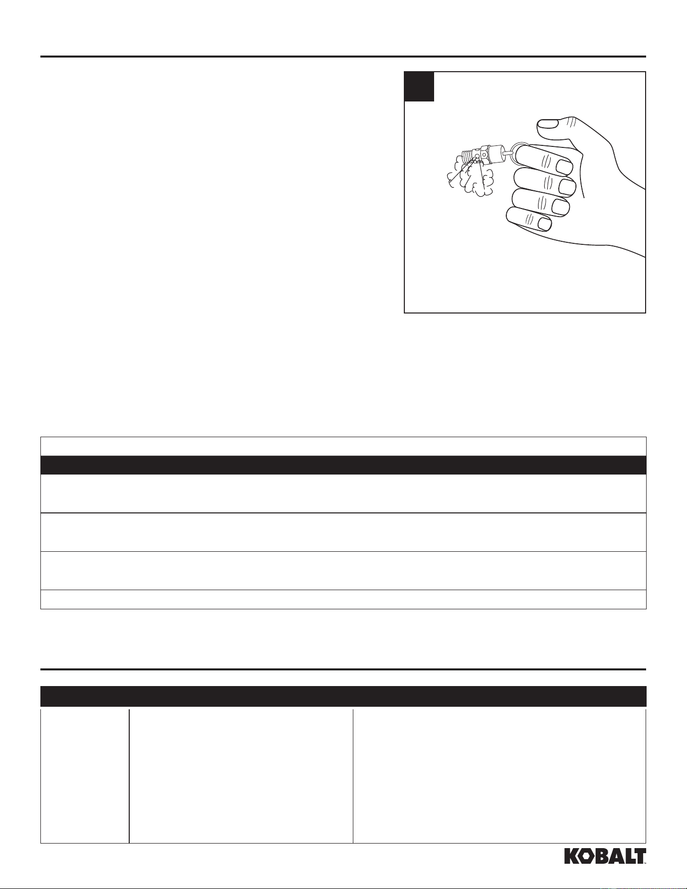
4. Drain Tank. Disconnect, tag and lock out
power source; release pressure. Drain
moisture from tank by opening drain valve
underneath tank (See Figure 2).
MOISTURE IN COMPRESSED AIR
Moisture in compressed air will form
into droplets as it comes from an air
compressor pump. When humidity is high
or when a compressor is in continuous
use for an extended period of time, this
moisture will collect in the tank. When
using a paint spray or sandblast gun,
this water will be carried from the tank
through the hose, and out of the gun as
droplets mixed with the spray material.
IMPORTANT: This condensation
will cause water spots in a paint job,
especially when spraying other than
water based paints. If sandblasting, it
will cause the sand to cake and clog the
gun, rendering it ineffective. A fi lter in the
air line, located as near to the gun as
possible, will help eliminate this moisture.
5. Check air filter to be sure it is clean. Replace
filter if filter is dirty.
2
1
Oil Fill Area
Oil Drain
Plug
kobalttools.com
17
CARE AND MAINTENANCE
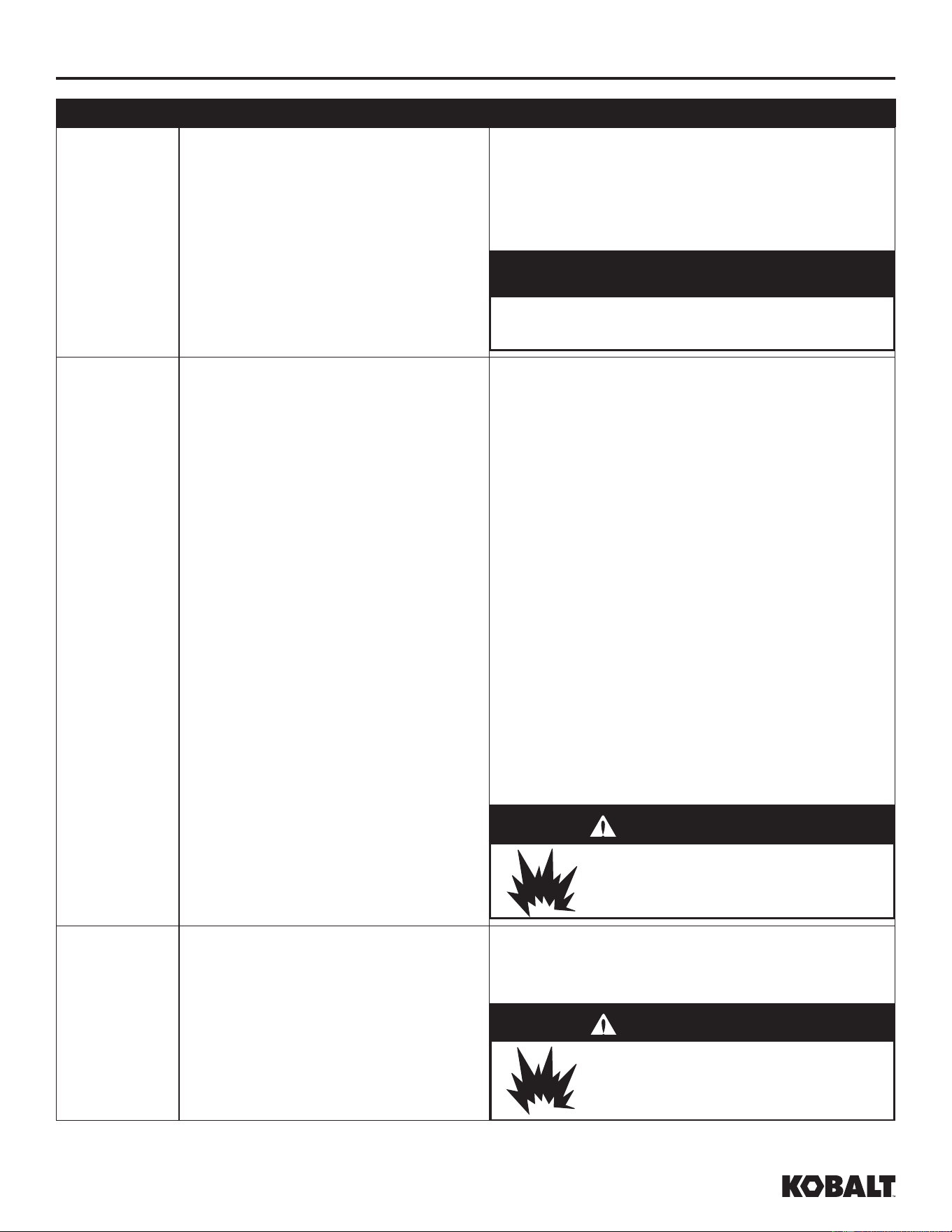
6. Check the safety valve by performing the following
steps:
a. Restore power to unit; turn pressure switch to the
AUTO position. Run until unit reaches 90 psi.
Turn pressure switch to OFF position.
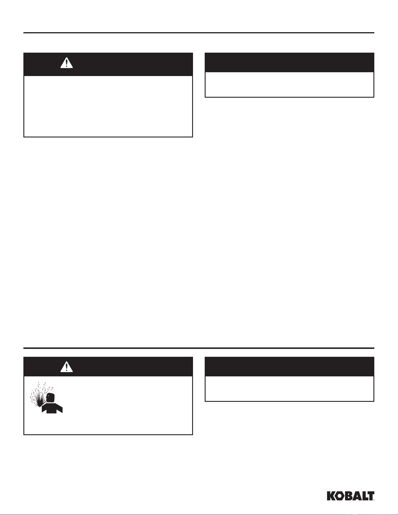
b. Wearing safety glasses and hearing protection,
pull the ring on the safety valve to release
pressure from compressor tank. Protect yourself
from fast-moving air being released; do not allow
fast-moving air to be directed toward your face
(See Figure 3).
c. The safety valve should automatically close at
approximately 40-50 psi. If the safety valve does
not allow air to be released when you pull on the
ring, or if it does not close automatically, it MUST
be replaced.
7. Check belt for signs of excessive wear. If belt shows
signs of wear, replace it. Check belt for proper
tension / alignment.
3
MAINTENANCE SCHEDULE
OPERATION DAILY WEEKLY MONTHLY 3 MONTHS
CHECK OIL LEVEL
●
DRAIN TANK
●
CHECK AIR FILTER
●
CHECK SAFETY VALVE
●
CLEAN UNIT
●
CHECK BELT TIGHTNESS
●
CHANGE OIL*
●
* Change oil after fi rst fi fty (50) hours of operation then perform oil changes every three (3)
months or two hundred (200) hours of run time, whichever comes fi rst.
TECHNICAL SERVICE
For information regarding the operation or repair of this product, please call 1-888-3KOBALT
(1-888-356-2258).
Low
discharge
pressure.
1. Air demand exceeds pump
capacity.
1. Reduce air demand or use a compressor with
more capacity.
2. Restricted air intake. 2. Clean or replace the air filter element.
3. Air leaks (fittings, tubing on
compressor, or plumbing outside of
system).
3. Listen for escaping air. Apply soap solution
to all fittings and connections. Bubbles will
appear at points of leakage. Tighten or replace
leaking fittings or connections. Use pipe thread
sealant.
TROUBLESHOOTING
PROBLEM POSSIBLE CAUSE CORRECTIVE ACTION
kobalttools.com
18
TROUBLESHOOTING
PROBLEM POSSIBLE CAUSE CORRECTIVE ACTION
Low
discharge
pressure.
(Continued)
4. Blown gaskets. 4. Replace any gaskets proven faulty on
inspection.
5. Leaking or damaged valves. 5. Remove head and inspect for valve breakage,
misaligned valves, damaged valve seats, etc.
Replace defective parts and reassemble.
CAUTION
Unit care and maintenance. Install a new
head gasket each time the head is removed.
Excessive
noise.
(knocking)
1. Loose motor pulley or flywheel. 1. Tighten pulley / flywheel clamp bolts and set-
screws.
2. Loose fasteners on pump or motor. 2. Tighten fasteners.
3. Lack of oil in crankcase. 3. Check for proper oil level; if low, check for
possible damage to bearings. Dirty oil can
cause excessive wear.
4. Worn connecting rod. 4. Replace connecting rod. Maintain oil level and
change oil more frequently.
5. Worn piston pin bores. 5. Remove piston assemblies from the
compressor and inspect for excess wear.
Replace excessively worn piston pin or pistons,
as required. Maintain oil level and change oil
more frequently.
6. Piston hitting the valve plate. 6. Remove the compressor head and valve plate
and inspect for carbon deposits or other foreign
matter on top of piston. Replace head and
valve plate using new gasket. See Lubrication
section for recommended oil.
7. Noisy check valve in compressor
system.
7. Replace check valve.
Risk of Explosion. Do not
disassemble check valve with air
pressure in tank.
DANGER
Pressure
switch does
not release
air when the
unit shuts
off.
Malfunctioning unloader valve on
pressure switch.
Replace the unloader valve if it does not release
the pressure for a short period of time when the
unit shuts off.
Risk of Explosion. Do not
disassemble unloader valve with
air pressure in tank.
DANGER
kobalttools.com
19
TROUBLESHOOTING
Large
quantity of
oil in the
discharge air
NOTE: In
an oil-lubed
compressor
there will
always be a
small amount
of oil in the
air stream.
1. Worn piston rings. 1. Replace with new rings. Maintain oil level and
change oil more frequently.
2. Compressor air intake restricted. 2. Clean or replace filter. Check for other
restrictions in the intake system.
3. Excessive oil in compressor. 3. Drain down to full level.
4. Wrong oil viscosity. 4. Use Mobil 1
®
10W-30 or full synthetic.
Water in
discharge air /
tank.
Normal operation. The amount of
water increases with humid weather.
1. Drain tank more often. At least daily.
2. Add a filter to reduce the amount of water in
the air line.
Motor hums
and runs
slowly or not
at all.
1. Low voltage. 1. Check incoming voltage. It should be
approximately 120 volts. Low voltage could be
due to wires (from breaker/fuse to outlet) being
too small in diameter and / or too long. Have a
qualified electrician check these conditions and
make repairs as needed.
2. Use of extension cord. 2. Do not use an extension cord. Use longer air
hose with larger diameter.
3. Too many devices on same circuit. 3. Limit the circuit to the use of compressor only.
4. Loose electrical connections. 4. Check all electrical connections.
5. Malfunctioning pressure switch -
contacts will not close.
5. Replace pressure switch.
6. Malfunctioning check valve. 6. Replace check valve.
Risk of Explosion. Do not
disassemble check valve with air
pressure in tank.
DANGER
7. Defective unloader valve on
pressure switch.
7. Replace unloader valve.
8. Defective motor capacitor(s). 8. Replace capacitor(s).
9. Defective motor. 9. Replace motor.
Reset
mechanism
cuts out
repeatedly
or circuit
breaker trips
repeatedly.
1. Lack of proper ventilation / room
temperature too high.
1. Move compressor to well-ventilated area.
2. Too many devices on same circuit. 2. Limit the circuit to the use of only the air
compressor.
3. Restricted air intake. 3. Clean or replace filter element.
4. Loose electrical connection. 4. Check all electrical connections.
PROBLEM POSSIBLE CAUSE CORRECTIVE ACTION
kobalttools.com
20
TROUBLESHOOTING
PROBLEM POSSIBLE CAUSE CORRECTIVE ACTION
Reset
mechanism
cuts out
repeatedly
or circuit
breaker trips
repeatedly.
(Continued)
5. Pressure switch shut-off pressure
set too high.
5. Replace pressure switch.
6. Low voltage. 6. Check incoming voltage. It should be
approximately 120 volts. Low voltage could be
due to wires (from breaker/fuse to outlet) being
too small in diameter and / or too long. Have a
qualified electrician check these conditions and
make repairs as needed.
7. Malfunctioning check valve. 7. Replace check valve.
Risk of Explosion. Do not
disassemble check valve with air
pressure in tank.
DANGER
8. Defective unloader valve on
pressure switch.
8. Replace unloader valve.
9. Defective motor capacitor(s). 9.Replace capacitor(s).
10. Malfunctioning motor. 10. Replace motor.
11. Low voltage. 11. Check incoming voltage. It should be
approximately 120 volts. Low voltage could be
due to wires (from breaker/fuse to outlet) being
too small in diameter and / or too long. Have a
qualified electrician check these conditions and
make repairs as needed.
Tank does
not hold
pressure
when
compressor
is off and the
shut off valve
is closed.
1. Air leaks (fittings, tubing on
compressor, or plumbing outside
system).
1. Check all connections with soap and water
solution. Tighten; or remove and apply sealant
to threads, then reassemble.
2. Worn check valve. 2. Replace check valve.
Risk of Explosion. Do not
disassemble check valve with air
pressure in tank.
DANGER
3. Check tank for cracks or pin holes. 3. Replace tank. Never repair a damaged tank.
Excessive
vibration.
1. Loose fasteners on pump or motor. 1. Tighten fasteners.
2. Belt needs replaced. 2. Replace with correct size.
3. Belt alignment. 3. Align flywheel and pulley.
kobalttools.com
21
TROUBLESHOOTING
PROBLEM POSSIBLE CAUSE CORRECTIVE ACTION
Pressure
switch
continuously
blows air out
the unloader
valve.
Malfunctioning check valve. Replace the check valve if the unloader valve on
the pressure switch bleeds off constantly when
unit shuts off.
Risk of Explosion. Do not
disassemble check valve with air
pressure in tank.
DANGER
WARRANTY
1. DURATION: From the date of purchase by the original purchaser as follows: Three Years.
2. WHO GIVES THIS WARRANTY: Campbell Hausfeld a Marmon/Berkshire Hathaway Company,
100 Production Drive, Harrison, Ohio, 45030.
3. WHO RECEIVES THIS WARRANTY (PURCHASER): The original purchaser (other than for
purposes of resale) of the compressor.
4. WHAT PRODUCTS ARE COVERED BY THIS WARRANTY: This air compressor.
5. WHAT IS COVERED UNDER THIS WARRANTY: Parts and Labor to remedy substantial
defects due to material and workmanship during the first year of ownership with the exceptions
noted below. Parts only to remedy substantial defects due to material and workmanship during
remaining term of coverage with exceptions noted below.
6. WHAT IS NOT COVERED UNDER THIS WARRANTY:
A. Implied warranties, including those of merchantability and FITNESS FOR A PARTICULAR
PURPOSE ARE LIMITED FROM THE DATE OF ORIGINAL PURCHASE AS STATED IN
THE DURATION. Some States do not allow limitations on how long an implied warranty
lasts, so the above limitations may not apply to you
B. ANY INCIDENTAL, INDIRECT, OR CONSEQUENTIAL LOSS, DAMAGE, OR EXPENSE
THAT MAY RESULT FROM ANY DEFECT, FAILURE, OR MALFUNCTION OF THE
CAMPBELL HAUSFELD PRODUCT. Some States do not allow the exclusion or limitations of
incidental or consequential damages, so the above limitation or exclusion may not apply to
you.
C. Any failure that results from an accident, purchaser’s abuse, neglect or failure to operate
products in accordance with instructions provided in the owner’s manual(s) supplied with
compressor.
D. Pre-delivery service, e.g. assembly, oil or lubricants, and adjustment.
E. Items or service that is normally required to maintain the product, i.e. lubricants, filters and
gaskets, etc.
kobalttools.com

22
WARRANTY
F. Additional items not covered under this warranty:
1. Excluded items pertaining to All Compressors
a. Any component damaged in shipment or any failure caused by installing or operating
unit under conditions not in accordance with installation and operation guidelines or
damaged by contact with tools or surroundings.
b. Pump or valve failure caused by rain, excessive humidity, corrosive environments or
other contaminants.
c. Cosmetic defects that do not interfere with compressor functionality.
d. Rusted tanks, including but not limited to rust due to improper drainage or corrosive
environments.
e. The following components are considered normal wear items and are not covered
after the first year of ownership. Electric motor, check valve, pressure switch, regulator,
pressure gauges, hose, tubing, pipe, fittings and couplers, screws, nuts, hardware
items, belts, pulleys, flywheel, air filter and housing, gaskets, seals, oil leaks, air leaks,
oil consumption or usage, piston rings.
f. Tank drain valves.
g. Damage due to incorrect voltage or improper wiring.
h. Other items not listed but considered general wear parts.
i. Pressure switches, air governors, load/unload devices, throttle control devices and
safety valves modified from factory settings.
j. Damage from inadequate filter maintenance.
k. Induction motors operated with electricity produced by a generator.
2. Excluded items specific to Lubricated Compressors:
a. Pump wear or valve damage caused by using oil not specified.
b. Pump wear or damage caused by any oil contamination.
c. Pump wear or damage caused by failure to follow proper oil maintenance guidelines,
operation below proper oil level or operation without oil.
G. Labor, service call, or transportation charges after the first year of ownership of stationary
compressors. Stationary compressors are defined as not including a handle or wheels.
7. RESPONSIBILITIES OF WARRANTOR UNDER THIS WARRANTY: Repair or replace, at
Warrantor’s option, compressor or component which is defective, has malfunctioned and/or
failed to conform within the duration of the specific warranty period.
8. RESPONSIBILITIES OF PURCHASER UNDER THIS WARRANTY:
A. Provide dated proof of purchase and maintenance records.
B. Call customer service at 1-888-3KOBALT (1-888-356-2258) to obtain your warranty service
options. Freight costs must be borne by the purchaser.
C. Use reasonable care in the operation and maintenance of the products as described in the
owner’s manual(s).
D. Repairs requiring overtime, weekend rates, or anything beyond the standard manufacturer
warranty repair labor reimbursement rate.
E. Time required for any security checks, safety training, or similar for service personnel to gain
access to facility.
F. Location of unit must have adequate clearance for service personnel to perform repairs and
be easily accessible.
9. WHEN WARRANTOR WILL PERFORM REPAIR OR REPLACEMENT UNDER THIS
WARRANTY: Repair or replacement will be scheduled and serviced according to the normal
work flow at the servicing location, and depending on the availability of replacement parts.
This Limited Warranty applies in the U.S., Canada and Mexico only and gives you specific legal
rights. You may also have other rights which vary from state to state or country to country.
kobalttools.com
23
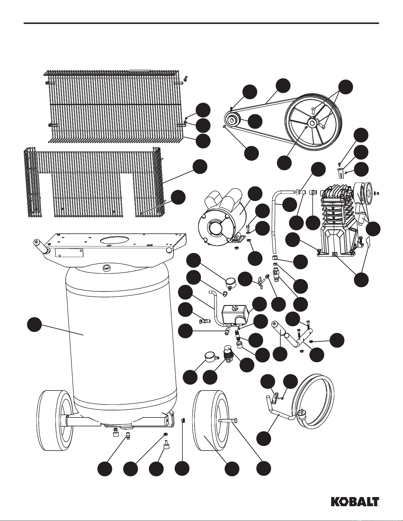
EXPLODED DRAWINGS
kobalttools.com
20
1
2 3
45
2
6
7
8
9
10
12 11
13
14
3537
14
36
23
21
22
34
44
32
45
33
4947
38
4039
31 29
42
25
27
41
48
31
26
46
30
28
23
19
24
43
16
15
17
18
7
7
7
24
EXPLODED DRAWINGS
PART DESCRIPTION PART NUMBER QTY.
1 TANK, 30 GALLONS AR067500CG 1
2 SPINLOCK NUT, 5/16"-18 ST146001AV 6
3 PNUEMATIC WHEEL, 10" WA006000AV 2
4 AXLE BOLT, 3/8"-16 X 3" ST084700AV 2
5 FLANGE NUT, 3/8"-16 ST033500AV 2
6 MOTOR, 2HP 120/240V MC019800SJ 1
7 COMPRESSOR PUMP VT482200AJ 1
8 SELF TAPPING SCREW, 5/16"-12 ST016500AV 4
9 WASHER, 5/16"
ST011200AV ▲
4
10 HEX HEAD BOLT, 5/16"-18 X 3/4" ST016000AV 4
11 CHECK VALVE CV221503SJ 1
12 QUICK CONNECT FITTING, 1/4" TUBE X 1/8" NPT - 1
13 RUBBER FERRULE, 1/2" TUBE ST085200AV 1
14 COMPRESSION NUT, 1/2" ST033001AV 2
15 MOTOR PULLEY PU015200AV 1
16 MOTOR KEY KE000900AV 1
17 SET SCREW, 1/4"-20 X 1/2" ST012200AV 1
18 BELT, AX48 BT020401AV 1
19 BELT GUARD BACK
BG313200AV ▲
1
20 BELT GUARD FRONT
BG313300AV ▲
1
21 BELT GUARD BRACKET BG220400AV 1
22 SELF TAPPING SCREW, #10-3/8" ST073278AV 1
23 SELF TAPPING SCREW, #5-5/8"
ST073277AV ▲
5
24 HEX NUT, #10-24 ST116201AV 4
25 REDUCING BUSHING, 1/2" X 1/4" NPT ST071428AV 1
26 REDUCING BUSHING, 1/4" X 1/8" NPT ST071407AV 1
27 PIPE NIPPLE, 1/4" NPT ST016800AV 1
28 HEX PIPE NIPPLE, 1/4" NPT HF002401AV 1
29 REGULATOR RE300900AV 1
30 ASME SAFETY VALVE, 175PSI V-215109AV 1
31 PRESSURE GAUGE, 300PSI GA016306AV 2
32 HANDLE HL705600AV 2
33 GRIP - 2
34 PTFE TUBE, 1/4" X 13" ST117802AV 1
Continued on next page
For replacement parts, call our customer service department at 1-888-3KOBALT (1-888-356-2258),
8:00 am - 8:00 pm, EST, Monday - Friday.
kobalttools.com
25
EXPLODED DRAWINGS
PART DESCRIPTION PART NUMBER QTY.
35 COMPRESSION FITTING ST159001AV 1
36 EXHAUST TUBE , 1/2" VT035801AP 1
37 BRASS FERRULE, 1/2" TUBE ST032900AV 1
38 POWER CORD, 120V EC012601AV 1
39 PRESSURE SWITCH CORD GRIP CW209500AV 1
40 STRAIN RELIEF SCREW ST209800AV 1
41 HEX HEAD SELF TAPPIN SCREW. #8 X 3/8" ST074407AV 2
42 REGULATOR DECAL DK700900AV 1
43 PLASTIC RETAINING CLIP
ST199700AV ▲
4
44 HANDLE BOLT, 1/4"-20 X 1.25" PM001901AV 4
45 HANDLE NUT, 1/4"-20 PM031101AV 4
46 MOTOR POWER CORD EC012800AV 1
47 DRAINCOCK, 1/4" D-1403 1
48 PRESSURE SWITCH CW218700AV 1
49 RUBBER FOOT ST162602AV 2
50 PUMP FLYWHEEL (NOT SHOWN) PU015901SJ 1
REPLACEMENT PARTS KITS
▲
BELT GUARD KIT VT490900AV
For replacement parts, call our customer service department at 1-888-3KOBALT (1-888-356-2258),
8:00 am - 8:00 pm, EST, Monday - Friday.
kobalttools.com
26
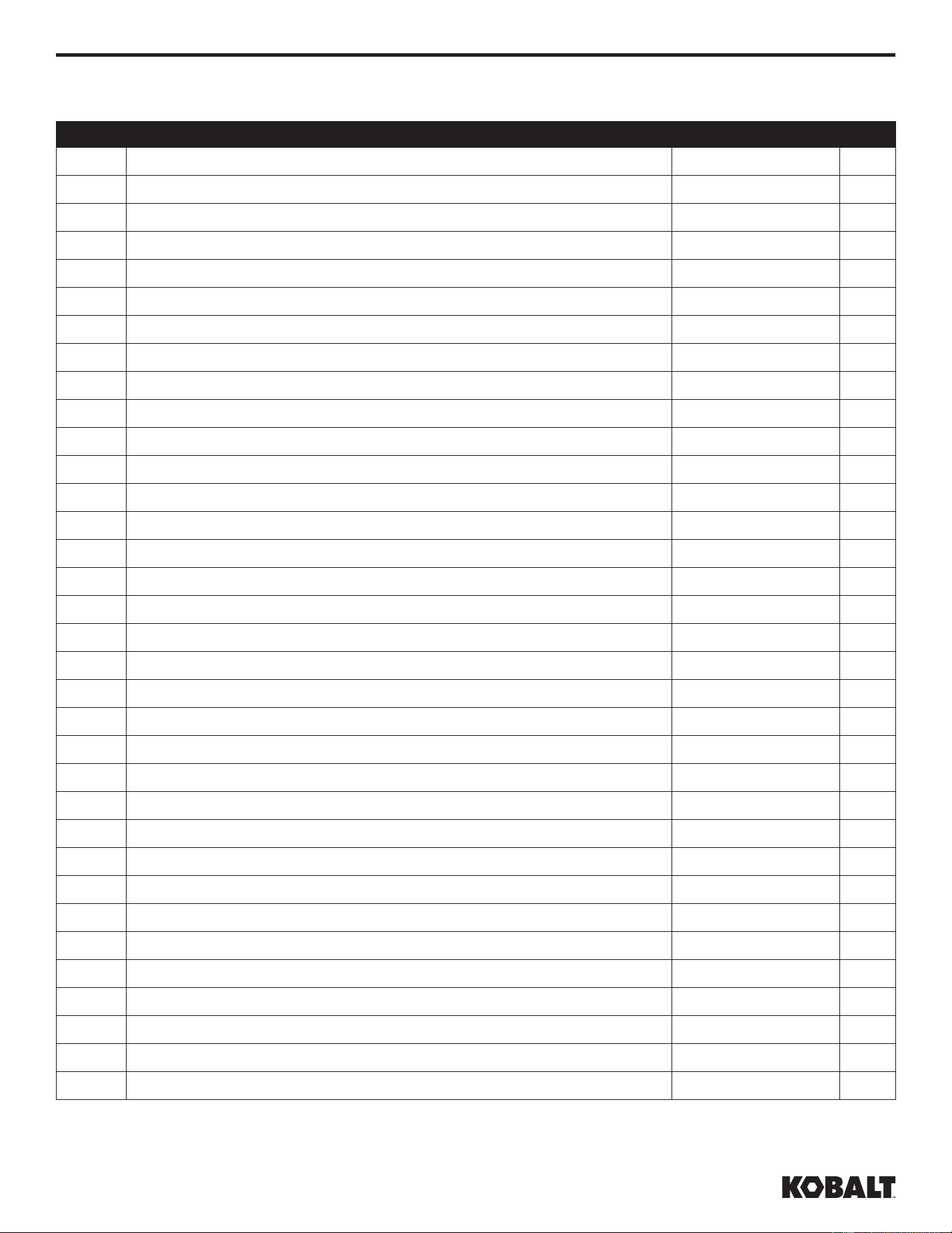
EXPLODED DRAWINGS
7
1
2
3
4
5
6
8
9
11
10
12
13
15
14
16
17
18
19
20
21
kobalttools.com
27
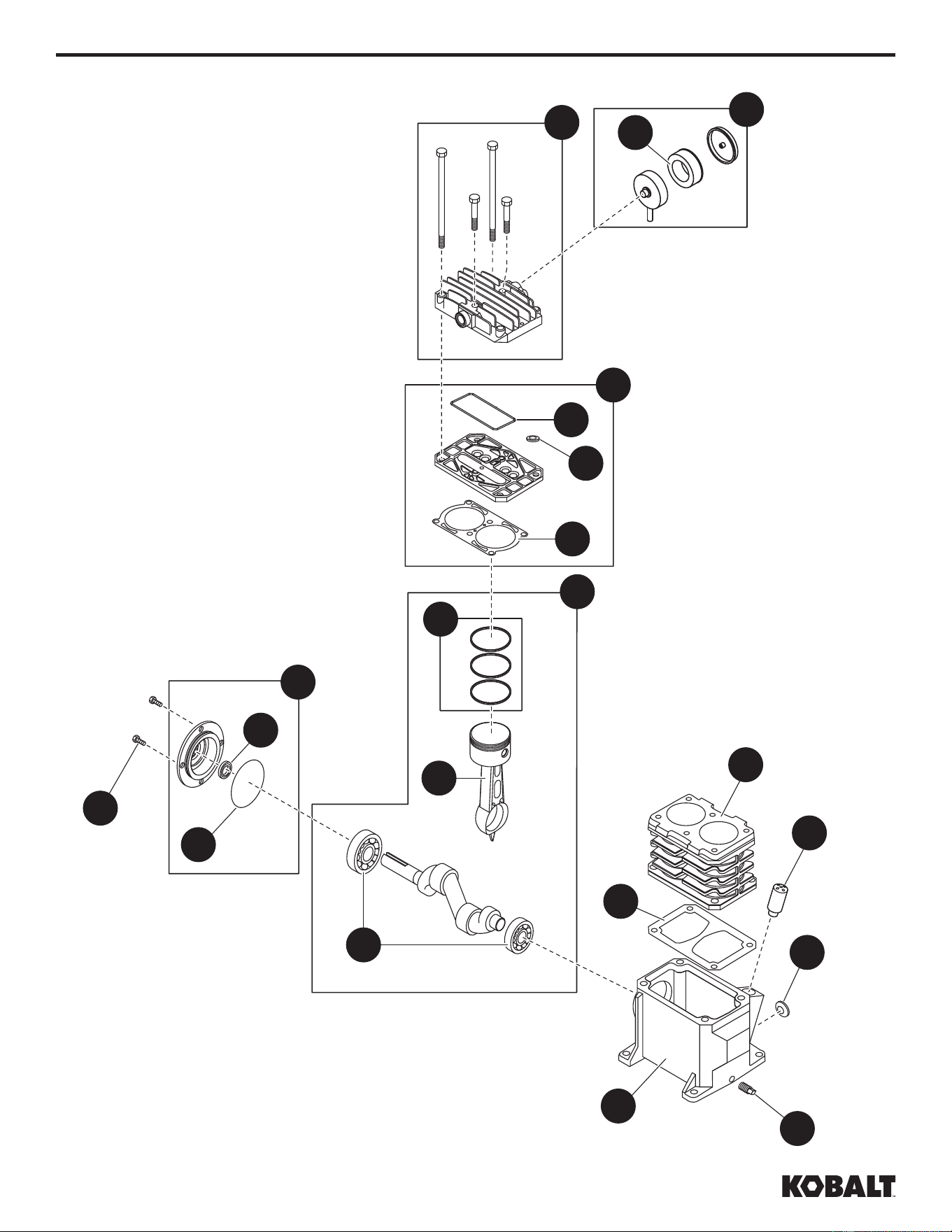
EXPLODED DRAWINGS
PART DESCRIPTION PART NUMBER QTY.
1 CRANKCASE -- 1
2 CRANKCASE GASKET
▲
1
3 BREATHER VH901100AV 1
4 CYLINDER VT040715AV 1
5 CYLINDER GASKET
▲
1
6 CONNECTING ROD AND PISTON ASSEMBLY VT020500AV 2
7 PISTON RING SET VT911200AV 2
8 BALL BEARING ST084202AV 2
9 CRANKSHAFT, BEARINGS, RODS, PISTON, RINGS ASSEMBLY -- 1
10 O-RING
▲
1
11 OIL SEAL ST129700AV 1
12 BEARING CAP ASSEMBLY VT040200AJ 1
13 M6 X 10 MM SCREW
❋
4
14 VALVE PLATE ASSEMBLY VT491100AV 1
15 VALVE PLATE MOLDED SEAL
▲
1
16 CYLINDER HEAD AND FASTENERS TQ900800AJ 1
17 AIR FILTER ASSEMBLY VH901700AV 1
18 1/8 INCH - 27 OIL DRAIN PLUG ST022300AV 1
19 SIGHT GLASS ST191700AV 1
20 AIR FILTER ELEMENT VH901800AV 1
21 O-RING VT036700AV 1
REPLACEMENT PARTS KITS
▲
GASKET KIT VT470900AJ
❋
STANDARD HARDWARE ITEM
For replacement parts, call our customer service department at 1-888-3KOBALT (1-888-356-2258),
8:00 am - 8:00 pm, EST, Monday - Friday.
kobalttools.com

28
NOTES
Printed in the U.S.A.
KOBALT
®
and the K Design
®
are registered
trademarks of LF, LLC. All Rights Reserved.
kobalttools.com