
RTH7400/RTH7500 Series
Programmable Thermostat
69-2487ES-01
Quick Installation Guide

69-2487ES—01 ii
Advanced Installation Guide
Installation is Easy
Label wires and remove your old thermostat
Install and wire your new thermostat
Set your new thermostat to match your heating/cooling
system
– This thermostat works with virtually all System
Types
– It is preset for the most common system
We are here to help.
Call 1-800-468-1502 for wiring
assistance before returning
the thermostat to the store.
1 69-2487ES—01
RTH7400/RTH7500 Series
1
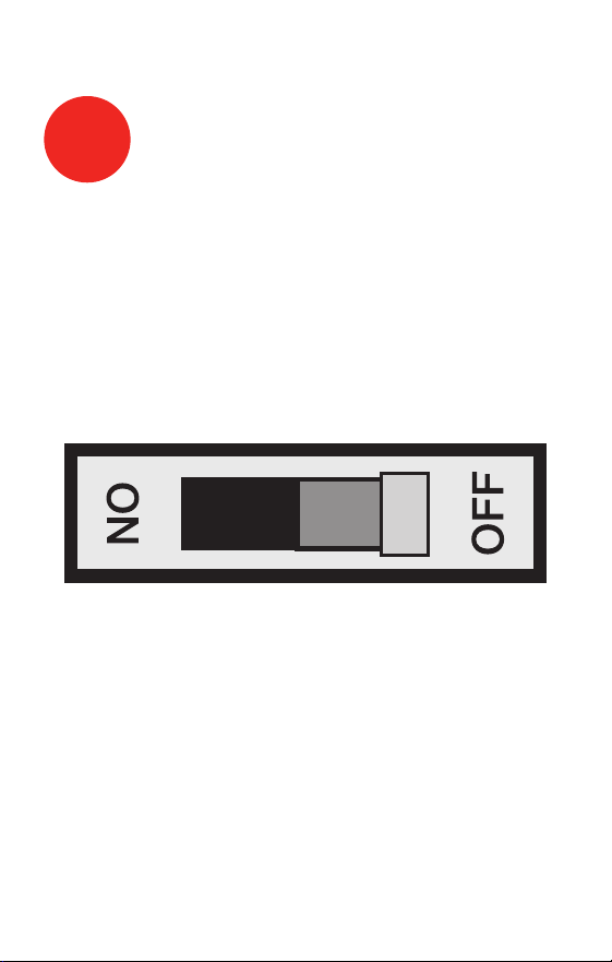
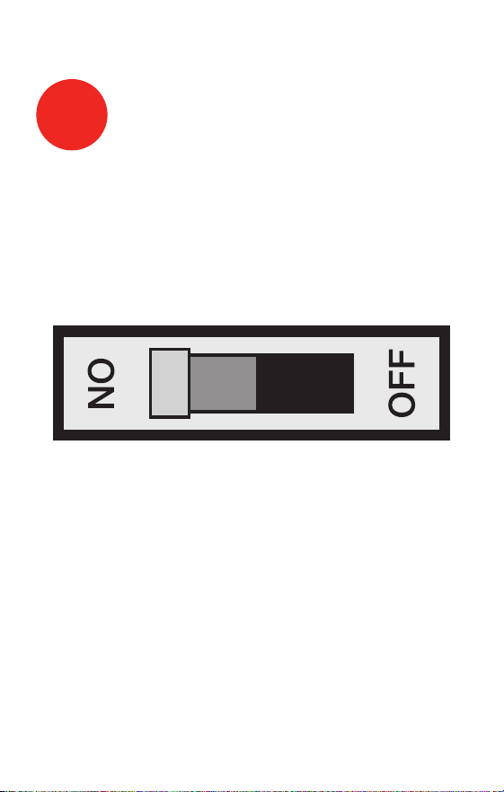
Turn Off Power to Heating/
Cooling System
M28097
69-2487ES—01 2
Advanced Installation Guide
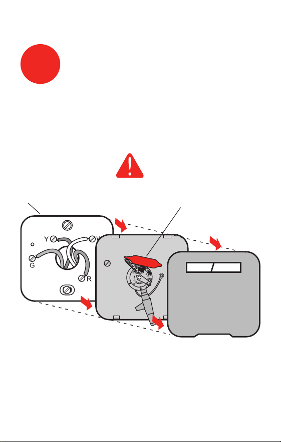
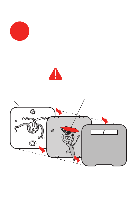
Remove old thermostat but leave wallplate with
wires attached.
2
Remove Old Thermostat
M28099
Leave wallplate
in place
Old thermostat
Cover
MERCURY NOTICE
Is there a sealed tube
containing mercury? If so,
see back cover for proper
disposal instructions.

3 69-2487ES—01
RTH7400/RTH7500 Series
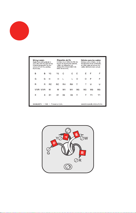
Label the wires using the supplied wire labels as you
disconnect them.
3
Label Wires with Tags
Wire Labels
M28100
M28093
NOTE: Jumper wire used on old thermostat? If yes, note
what letters the jumper connected and review in wiring
section.

69-2487ES—01 4
Advanced Installation Guide
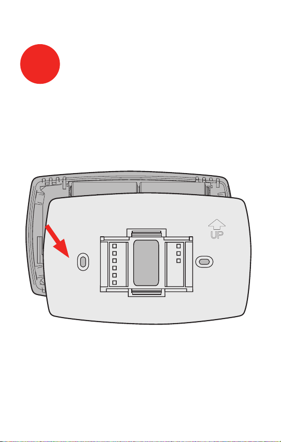
Remove wallplate from the new thermostat and mount
onto wall.
M28073
4
Separate Wallplate from
New Thermostat
Wallplate
5 69-2487ES—01
RTH7400/RTH7500 Series
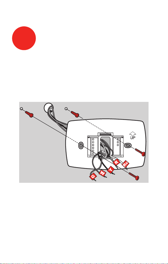
Mount the new wallplate using the included screws
and anchors.
5
Mount Wallplate
M28094
Drill 3/32-in. holes for plaster
Drill 3/16-in. holes for drywall
Use hammer to tap the anchors into the wall.
69-2487ES—01 6
Advanced Installation Guide
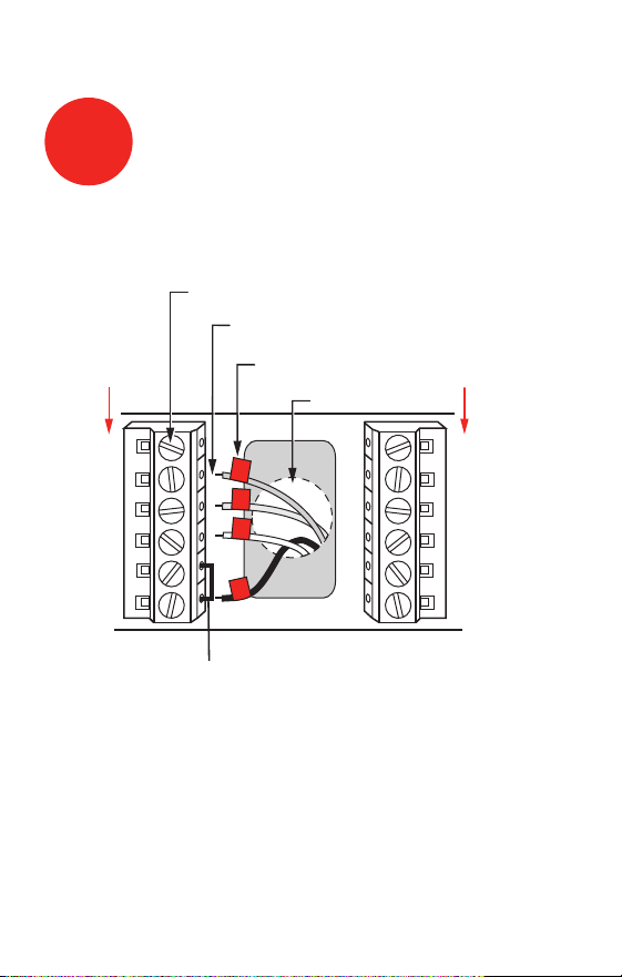
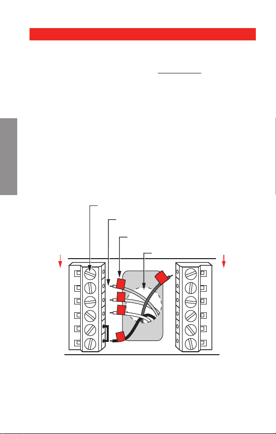
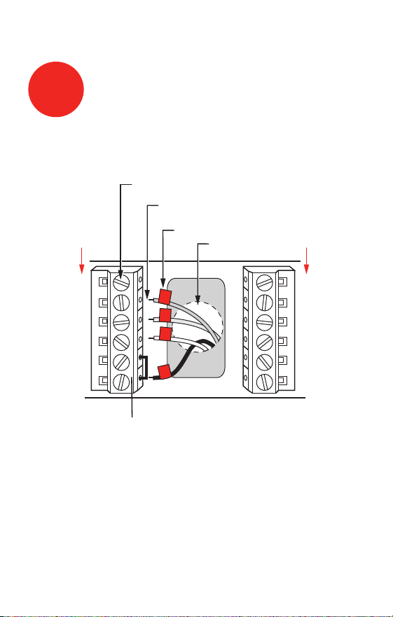
Simply match wire labels.
Remove metal jumper if you have both R and Rc wires.
M28070
W2
Y2
C
G
Y
W
RC
R
LABELED WIRES
SCREW
CONVENTIONAL
INSERT WIRES
THEN TIGHTEN SCREWS
WIRE HOLE
Y
G
R
W
CONVENTIONAL
6
Connect Wires
Labels don’t match? See page 21.
Have a Heat Pump system? See pages 22–23.
We are here to help.
Call 1-800-468-1502 for wiring assistance.
7 69-2487ES—01
RTH7400/RTH7500 Series
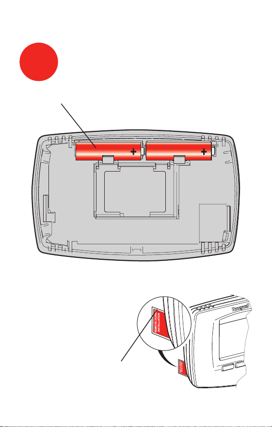
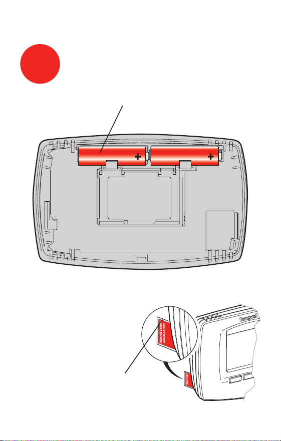
Install two AA alkaline batteries and remove tab.
M28101
Back of thermostat
Remove tab.
M28102
7
Install Batteries

69-2487ES—01 8
Advanced Installation Guide
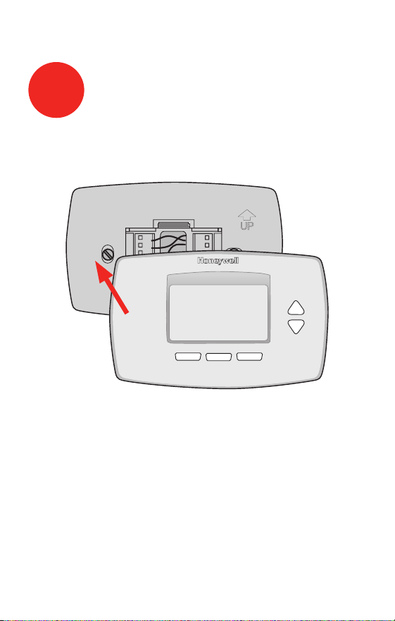
Install thermostat onto the wallplate on the wall.
M28103
8
Install Thermostat onto Wallplate
9 69-2487ES—01
RTH7400/RTH7500 Series
Turn the power back on to the heating/cooling system.
9
Turn Power Back On
M28098
69-2487ES—01 10
Advanced Installation Guide
Go Back Next Done
6
15
2006
M28095
Month Year Day
10
Set Time and Date
Press s or t to set month, then press NEXT.
Press s or t to set day, then press NEXT.
Press s or t to set year, then press DONE.
Press s or t to set time, then press DONE to save and
exit.
Done
10:10
M28096

11 69-2487ES—01
RTH7400/RTH7500 Series
If your system type is:
q Single Stage Heat and Cool
Congratulations, you’re done!
If your system type is:
q Multistage Heat and Cool
q Heat Pump* without Backup Heat
q Heat Pump* with Backup Heat
q Heat Only
q Cool Only
Continue with advanced installation
on next page to match your thermostat to your sytem type.
*Heat Pump—an air conditioner that provides cooling
in the summer, and also runs in reverse in the winter to
provide heating.
If you are not sure of your system type or if you have
other questions, call us toll-free at 1-800-468-1502.
This thermostat works on 24 volt or 750 mV systems. It
will NOT work on 120/240 Volt systems.
11
If your system type is...

Advanced Installation
System setup ......................................................................13
Wiring ..................................................................................21
Troubleshooting ..................................................................24
Customer assistance .........................................................26
Limited warranty .................................................................27
RTH7400/RTH7500 Series
13 69-2487ES—01
About your new thermostat
SETUP WIRING ASSISTANCE TROUBLESHOOTING
System & Fan ScheduleClock & More
20
0120
M27459
SystemFan Done
20
0120
M28069
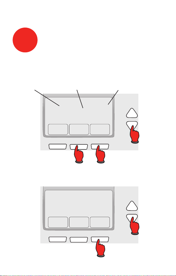
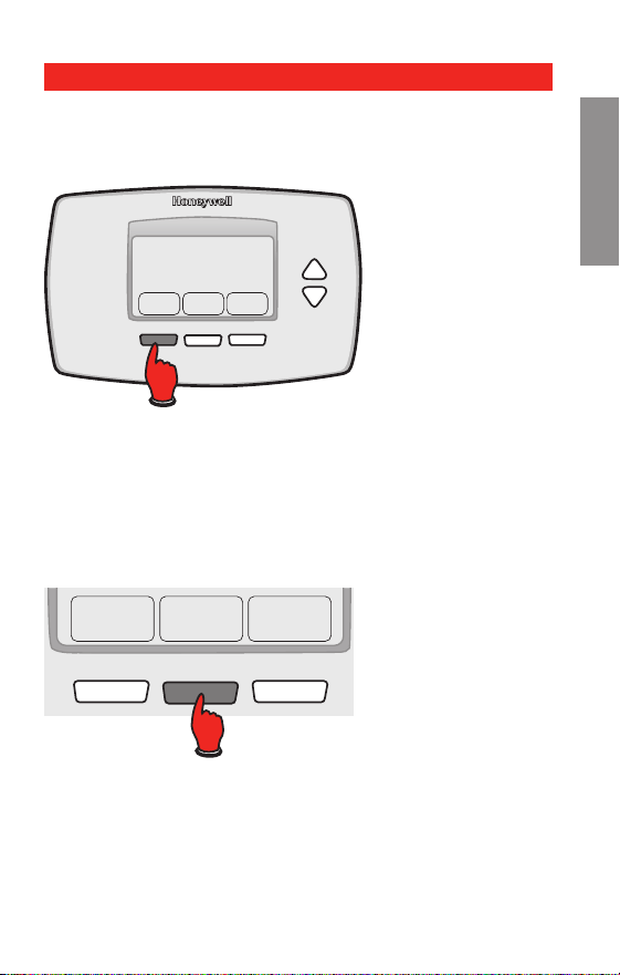
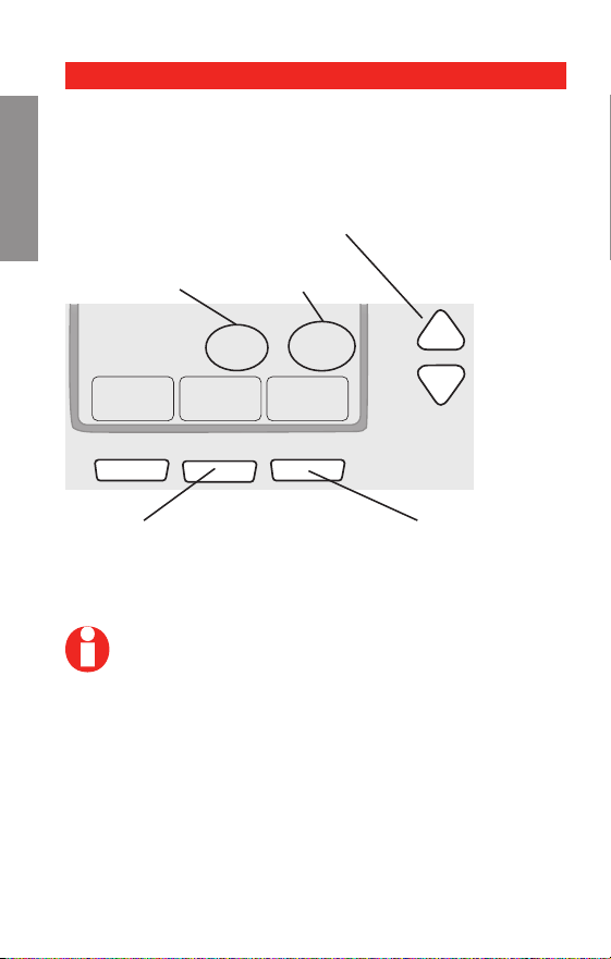
Step 1
Press and release the left button.
Step 2
Press and hold the center button until the screen
changes (approximately 5 seconds).
System setup
Advanced Installation Guide
69-2487ES—01 14
About your new thermostat
SETUPWIRINGASSISTANCETROUBLESHOOTING
Go Back Next Done
20
0120
Function
Setting
Press s t to change setting.
NOTE: Some functions in the following pages
may not appear due to previous selections
made.
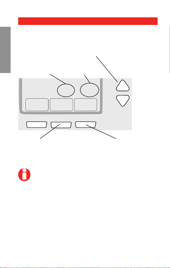
Press NEXT to advance to
next function.
Use this navigation to set and change settings on
pages 15-20.
Press DONE to save &
exit.
Navigating setting changes

RTH7400/RTH7500 Series
15 69-2487ES—01
About your new thermostat
SETUP WIRING ASSISTANCE TROUBLESHOOTING
NOTE: If you set the time and date as shown on
page 10, press NEXT to function 0170 and go to
page 16.
See page 14 to navigate between functions.
Function Settings & Options
0120 Year Setting
(rst two
digits)
Press s/t to change the rst two
digits of the year:
20 = Year 20xx
21 = Year 21xx
Press NEXT
0130 Year Setting
(second two
digits)
Press s/t to change the last two
digits of the year:
01 - 99 (i.e., 2001 - 2099)
Press NEXT
0140 Month Setting
Press s/t to change the current
month:
01 - 12 (i.e., January - December)
Press NEXT
0150 Date Setting
Press s/t to change the current
date:
01 - 31
Press NEXT
System setup

Advanced Installation Guide
69-2487ES—01 16
About your new thermostat
SETUPWIRINGASSISTANCETROUBLESHOOTING
See page 14 to navigate between functions.
Function Settings & Options
0170 Select System
Type
Press s/t to select your system
type:
1 Heat/cool: Gas, oil or electric
heating with central air condi-
tioning.
2 Heat pump: Heat pump with-
out backup or auxiliary heat.
3 Heat only: Gas, oil or electric
heat without central air condi-
tioning.
4 Heat only with fan: Gas, oil or
electric heat without central air
conditioning.
5 Hot water heat only (no fan):
Gas, oil or hot water heat with-
out central air conditioning.
6 Cool only: Central air condi-
tioning only.
7 Heat pump: Heat pump with
backup or auxiliary heating.
8 Heat/Cool Multiple stages:
2 heat stages (wires on W and
W2), 2 cooling stages (wires on
Y and Y2).
9 Heat/Cool Multiple stages:
2 heat stages (wires on W and
W2), 1 cooling stage (wire on
Y).
10 Heat/Cool Multiple stages: 1
heat stage (wire on W), 2 cool-
ing stages (wires on Y and Y2).
Press NEXT
System setup

RTH7400/RTH7500 Series
17 69-2487ES—01
About your new thermostat
SETUP WIRING ASSISTANCE TROUBLESHOOTING
See page 14 to navigate between functions.
Function Settings & Options
0180 Heating Fan
Control
Press s/t to select your heating
system & fan control:
0 Gas or oil heat: Use this
setting if you have a gas or
oil heating system (system
controls fan operation).
1 Electric heat: Use this setting
if you have an electric heating
system (thermostat controls fan
operation).
Press NEXT
0190 Heat Pump
Changeover
Valve (for heat
pumps only)
Press s/t to select whether your
changeover valve is used in heating
or cooling:
0 Cooling changeover valve:
Use this setting if you con-
nected a wire labeled “O” to
the O/B terminal (see page 22).
1 Heating changeover valve:
Use this setting if you con-
nected a wire labeled “B” to the
O/B terminal (see page 23).
Press NEXT
System setup
NOTE: Some functions in the following pages
may not appear due to previous selections
made.

Advanced Installation Guide
69-2487ES—01 18
About your new thermostat
SETUPWIRINGASSISTANCETROUBLESHOOTING
See page 14 to navigate between functions.
Function Settings & Options
0240 Heating Cycle
Rate
Press s/t to select your heating
system:
5 Gas or oil furnace: Standard
gas/oil furnace (less than 90%
efficiency).
9 Electric furnace: Electric
heating systems.
3 Hot water or high-efficiency
furnace: Hot water system or
gas furnace (more than 90%
efficiency).
1 Gas/oil steam or gravity
system: Steam or gravity heat
systems.
Press NEXT
0270 Emergency
Heat Cycle
Rate (heat
pumps only)
Press s/t to select your heating
system:
9 Electric furnace: Electric
heating systems.
5 Gas or oil furnace: Standard
gas/oil furnace (less than 90%
efficiency).
3 Hot water or high-efficiency
furnace: Hot water system or
gas furnace (more than 90%
efficiency).
1 Gas/oil steam or gravity
system: Steam or gravity heat
systems.
Press NEXT
System setup
NOTE: Some functions in the following pages
may not appear due to previous selections
made.

RTH7400/RTH7500 Series
19 69-2487ES—01
About your new thermostat
SETUP WIRING ASSISTANCE TROUBLESHOOTING
See page 14 to navigate between functions.
Function Settings & Options
0300 Manual/Auto
Changeover
Press s/t to select manual or
automatic changeover:
0 Manual changeover (Heat/Cool/
Off).
1 Automatic changeover (Heat/
Cool/Auto/Off). Automatically
turns on Heat or Cool based
on room temperature. Note:
System maintains minimum 3°F
difference between heat and
cool settings.
Press NEXT
0320 Temperature
Format (°F/°C)
Press s/t to set the temperature
display format:
0 Fahrenheit
1 Celsius
Press NEXT
0330 Daylight
Saving Time
On/Off
Press s/t to select an option:
0 Off: No adjustment for daylight
saving time.
1 On: Auto-change to daylight
saving time (for areas that do
not use the new 2007 DST
calendar).
2 On: Auto-change to daylight
saving time (2007 and beyond,
for areas that use the new 2007
DST calendar).
Press NEXT
System setup
NOTE: Some functions in the following pages
may not appear due to previous selections
made.

Advanced Installation Guide
69-2487ES—01 20
About your new thermostat
SETUPWIRINGASSISTANCETROUBLESHOOTING
See page 14 to navigate between functions.
Function Settings & Options
0500 Furnace Filter
Change
Reminder
Press s/t to set the desired
reminder interval:
0 Off (no reminder)
1 Reminder in about 1 month
2 Reminder in about 3 months
3 Reminder in about 6 months
4 Reminder in about 9 months
5 Reminder in about 1 year
6 Reminder in about 3 years
Press NEXT
0530 Smart
Response
®
Technology
Press s/t to turn this feature on or
off (see Operating Manual for more
information about this feature):
1 On
0 Off
Press NEXT
0640 Clock Format
Press s/t to set the clock display
format:
12 12-hour clock (i.e., “3:30 pm”)
24 24-hour clock (i.e., “15:30”)
Press DONE to save and exit setup.
Congratulations, you’re done!
System setup
RTH7400/RTH7500 Series
21 69-2487ES—01
About your new thermostat
SETUP WIRING ASSISTANCE TROUBLESHOOTING
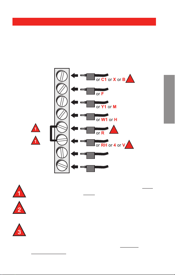
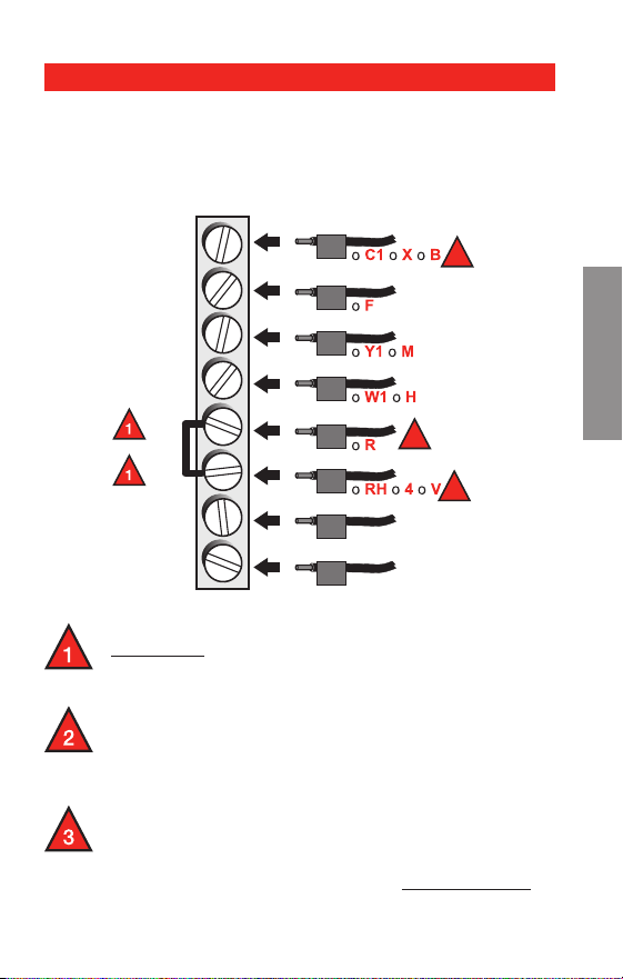
Remove metal jumper connecting R and Rc only
if you must connect both R and Rc wires.
If your old thermostat had both R and RH wires,
remove metal jumper. Connect the R wire to the
Rc terminal, and the RH wire to the R terminal.
If your old thermostat had only 1 C or C1
wire, connect it to the C terminal. If your old
thermostat had 2 C or C1 wires, wrap each
separately with electrical tape and do not
connect them.
Wiring—conventional system
Alternate wiring (conventional systems)
If labels do not match terminals, connect wires as
shown here (see notes, below).
C
G
Y
W
RC
R
W2
Y2
Y2
W2
W
Y
G
MCR32160
R
2
Rc
2
C
3
Advanced Installation Guide
69-2487ES—01 22
About your new thermostat
SETUPWIRINGASSISTANCETROUBLESHOOTING
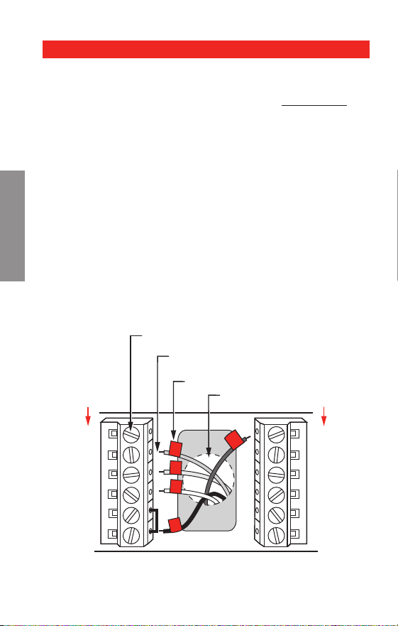
Connect wires: Heat Pump
1. Match each labeled wire with same letter on new
thermostat.
2. Use a screwdriver to loosen screws, insert wires into
hole under screw, then tighten screws until wire is
secure.
3. If E and Aux do not each have a wire connected,
use a small piece of wire to connect them to each
other.
4. Push any excess wire back into the wall opening.
Labels don’t match?
If labels do not match letters on thermostat, see page
23.
M28104
Aux
E
L
C
G
Y
O/B
RC
R
LABELED WIRES
SCREW
HEAT PUMP
INSERT WIRES
THEN TIGHTEN SCREWS
WIRE HOLE
Y
G
R
Aux
O
HEAT PUMP
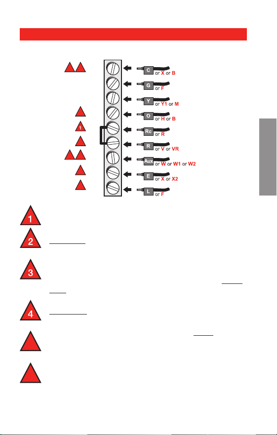
Wiring—heat pump
Wiring complete, return to Step 7.
RTH7400/RTH7500 Series
23 69-2487ES—01
SETUP WIRING ASSISTANCE TROUBLESHOOTING
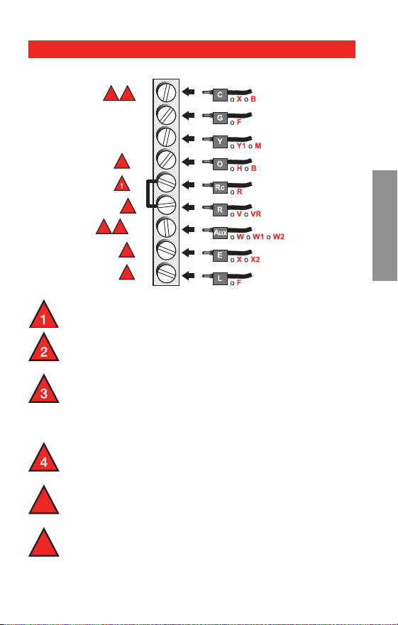
Wiring—heat pump
Leave metal jumper in place, connecting R & Rc
terminals.
If your old thermostat had both V and VR wires,
stop now and contact a qualified contractor for
help.
If your old thermostat had separate O and B
wires, attach the B wire to the C terminal. If
another wire is attached to the C terminal, stop
now and contact a qualified contractor for help.
If your old thermostat had Y1, W1 and W2 wires,
stop now and contact a qualified contractor for
help.
If L terminal is used, C terminal wire must be
connected (contact a contractor if there is no C
wire).
If E and Aux terminals do not each have a wire
connected, use a small piece of wire to connect
them to each other.
5
6
Alternate wiring (for heat pumps only)
Wiring complete, return to Step 7.
2
3
5
3 5
4
6
6
MCR32161
C
G
Y
O/B
RC
R
AUX
E
L

Advanced Installation Guide
69-2487ES—01 24
Troubleshooting
SETUPWIRINGASSISTANCETROUBLESHOOTING
If you have difficulty with your thermostat, please try
the following suggestions.
Most problems can be corrected quickly and easily.
Display is blank
Make sure fresh AA alkaline batteries
are properly installed (see
page 7).
Cannot change
system setting
to Cool
Check Function 0170: System Type
to make sure it is set to match your
heating and cooling equipment (see
page 16).
Fan does not
turn on when
heat is required
Check Function 0180: Heating Fan
Control to make sure it is set to match
your heating equipment (see page 17).
Heating system
is running in
cool mode
Check Function 0170: System Type
to make sure it is set to match your
heating and cooling equipment (see
page 16).
Red light is on
If thermostat is in Emergency Heat
mode the red light is normal. It shows
that the thermostat is in emergency
heat mode.
If thermostat is not in Emergency Heat
mode, contact a qualied service con-
tractor for repair.

RTH7400/RTH7500 Series
25 69-2487ES—01
Troubleshooting
SETUP WIRING ASSISTANCE TROUBLESHOOTING
Heating or cool-
ing system does
not respond
Press SYSTEM to set system to Heat.
Make sure the temperature is set higher
than the Inside temperature.
Press SYSTEM to set system to Cool.
Make sure the temperature is set lower
than the Inside temperature.
Check circuit breaker and reset if
necessary.
Make sure power switch at heating &
cooling system is on.
Make sure furnace door is closed
securely.
Wait 5 minutes for the system to
“Wait” appears
on the screen
Compressor protection feature is
engaged. Wait 5 minutes for the system
to restart safely, without damage to the
compressor.
Heat pump is-
sues cool air in
heat mode, or
warm air in cool
mode
Check Function 0190: Heat Pump
Changeover Valve to make sure it is
properly congured for your system
(see page 17).

Advanced Installation Guide
69-2487ES—01 26
SETUPWIRINGASSISTANCETROUBLESHOOTING
For assistance with this product, please visit
http://yourhome.honeywell.com
or call Honeywell Customer Care toll-free at
1-800-468-1502.
Customer assistance

27 69-2487ES—01
RTH7400/RTH7500 Series
Honeywell warrants this product, excluding battery, to be free
from defects in the workmanship or materials, under normal use
and service, for a period of one (1) year from the date of purchase
by the consumer. If at any time during the warranty period the
product is determined to be defective or malfunctions, Honeywell
shall repair or replace it (at Honeywell’s option).
If the product is defective,
(i) return it, with a bill of sale or other dated proof of purchase, to
the place from which you purchased it; or
(ii) call Honeywell Customer Care at 1-800-468-1502. Customer
Care will make the determination whether the product should be
returned to the following address: Honeywell Return Goods, Dock
4 MN10-3860, 1985 Douglas Dr. N., Golden Valley, MN 55422, or
whether a replacement product can be sent to you.
This warranty does not cover removal or reinstallation costs. This
warranty shall not apply if it is shown by Honeywell that the defect
or malfunction was caused by damage which occurred while the
product was in the possession of a consumer.
Honeywell’s sole responsibility shall be to repair or replace the
product within the terms stated above. HONEYWELL SHALL
NOT BE LIABLE FOR ANY LOSS OR DAMAGE OF ANY KIND,
INCLUDING ANY INCIDENTAL OR CONSEQUENTIAL DAMAGES
RESULTING, DIRECTLY OR INDIRECTLY, FROM ANY BREACH
OF ANY WARRANTY, EXPRESS OR IMPLIED, OR ANY OTHER
FAILURE OF THIS PRODUCT. Some states do not allow the exclu-
sion or limitation of incidental or consequential damages, so this
limitation may not apply to you.
THIS WARRANTY IS THE ONLY EXPRESS WARRANTY
HONEYWELL MAKES ON THIS PRODUCT. THE DURATION OF
ANY IMPLIED WARRANTIES, INCLUDING THE WARRANTIES
OF MERCHANTABILITY AND FITNESS FOR A PARTICULAR
PURPOSE, IS HEREBY LIMITED TO THE ONE-YEAR DURATION
OF THIS WARRANTY.
Some states do not allow limitations on how long an implied war-
ranty lasts, so the above limitation may not apply to you. This
warranty gives you specific legal rights, and you may have other
rights which vary from state to state.
If you have any questions concerning this warranty, please
write Honeywell Customer Relations, 1985 Douglas Dr, Golden
Valley, MN 55422 or call 1-800-468-1502. In Canada, write Retail
Products ON15-02H, Honeywell Limited/ Honeywell Limitée, 35
Dynamic Drive, Toronto, Ontario M1V4Z9.
1-year limited warranty
Automation and Control Solutions
Honeywell International Inc.
1985 Douglas Drive North
Golden Valley, MN 55422
Honeywell Limited-Honeywell Limitée
35 Dynamic Drive
Toronto, Ontario M1V 4Z9
yourhome.honeywell.com
® U.S. Registered Trademark.
© 2010 Honeywell International Inc.
69-2487ES—01 M.S. 06-10
Printed in U.S.A.
This thermostat contains a Lithium battery which may
contain Perchlorate material.
Perchlorate Material—special handling may apply,
See www.dtsc.ca.gov/hazardouswaste/perchlorate
MERCURY NOTICE: Do not place your old
thermostat in the trash if it contains mercury
in a sealed tube. Contact your local waste
management authority for instructions regarding
recycling and proper disposal.
CAUTION: To avoid possible compressor
damage, do not run air conditioner if the outside
temperature drops below 50°F (10°C).
69-2487ES-01
Serie RTH7400/RTH7500
Termostato programable
Guía de instalación rápida

69-2487ES—01 ii
Guía de instalación rápida
¡La instalación es fácil!
Rotule los cabes y retire el termostato viejo
Instale y conecte los cables de su nuevo termostato
Ajuste su nuevo termostato para que concuerde con
su sistema de calefacción/refrigeración
– Este termostato funciona prácticamente con
todos los tipos de sistemas
– Está preconfigurado para el sistema más común
Estamos aquí para ayudarle.
Llame al 1-800-468-1502 para
obtener asistencia con el
cableado antes de devolver
el termostato a la tienda.

1 69-2487ES—01
Serie RTH7400/RTH7500
1
Desconecte la alimentación
en el sistema de calefacción/
refrigeración
M28097
69-2487ES—01 2
Guía de instalación rápida
Retire el termostato existente pero deje la placa de
montaje con los cables adheridos.
2
Remueva su viejo termostato
M28099
AVISO SOBRE EL MERCURIO
¿Hay un tubo sellado que
contiene mercurio? Si es así,
consulte en la cubierta de este
manual las instrucciones para
su desecho apropiado.
Deje la placa de
montaje en su
lugar
Termostato viejo
Cubierta
3 69-2487ES—01
Serie RTH7400/RTH7500
Identifique los cables a medida que los desconecta,
utilizando las etiquetas que se suministran.
3
Identifique los cables con
etiquetas
Rótulos para los cables
M28100
M28093
NOTA: Jumper wire used on old thermostat? If yes, note
what letters the jumper connected and review in wiring
section.
69-2487ES—01 4
Guía de instalación rápida
Retire la placa de montaje del termostato nuevo y móntela
en la pared.
M28073
4
Separe la placa de montaje del
termostato nuevo
Placa de montaje

5 69-2487ES—01
Serie RTH7400/RTH7500
Monte la nueva placa de montaje utilizando los tornillos y
anclajes que se suministran.
5
Coloque la placa de montaje
M28094
Taladre agujeros de 3/32 in. (2,4 mm) en yeso
Taladre agujeros de 3/16 in. (4,8 mm) en paneles de yeso
Use hammer to tap the anchors into the wall.
69-2487ES—01 6
Guía de instalación rápida
Simplemente haga corresponder las etiquetas de los
cables.
Retire el empalme metálico si tiene los cables “R” y “Rc”.
MS28070
W2
Y2
C
G
Y
W
RC
R
CABLES ETIQUETADOS
TORNILLO
CONVENCIONAL
INSERTE LOS CABLES Y
APRIETE LOS TORNILLOS
ORIFICIO DE
CABLEADO
Y
G
R
W
CONVENCIONAL
6
Conecte los cables
¿Los rótulos no coinciden? Vea la página 21.
¿Tiene un sistema de bomba de calor? Ver páginas
22-23.
Estamos aquí para ayudarle.
Llame al 1-800-468-1502 para asistencia con el
cableado.
7 69-2487ES—01
Serie RTH7400/RTH7500
Instale dos baterías alcalinas AA en la parte de atrás del
termostato.
M28101
Parte de atrás del termostato
Retire la lengüeta.
M28102
7
Instale las baterías
69-2487ES—01 8
Guía de instalación rápida
Instale el termostato en la placa de montaje en la pared.
M28103
8
Instale el termostato en la placa
de montaje

9 69-2487ES—01
Serie RTH7400/RTH7500
Active nuevamente el suministro eléctrico del sistema de
calefacción/aire acondicionado.
9
Active nuevamente el
suministro eléctrico
M28098

69-2487ES—01 10
Guía de instalación rápida
Go Back Next Done
6
15
2006
M28095
El mes El año La fecha
10
Ajuste de fecha y hora
Oprima s o t para ajustar el mes, después oprima NEXT.
Oprima s o t para ajustar la fecha, después oprima NEXT.
Oprima s o t para ajustar el año, después oprima DONE.
Oprima s o t para ajustar la hora, después oprima
DONE para salir y guardar los ajustes.
Done
10:10
M28096

11 69-2487ES—01
Serie RTH7400/RTH7500
Si su tipo de sistema es:
q Calor y frío de una sola etapa
¡Felicitaciones, ya está listo!
Si su tipo de sistema es:
q Calor y frío de etapas múltiples
q Bomba de calor* sin calor de respaldo
q Bomba de calor* con calor de respaldo
q Solo calor
q Solo frío
Continúe con la instalación avanzada
en la próxima página para adaptar el termostato a su
tipo de sistema.
*Bomba de calor —un acondicionador de aire que
proporciona enfriamiento en el verano y también funciona
en reversa en el invierno, proporcionando calor.
Si no está seguro del tipo de sistema que tiene o si
tiene otras preguntas, llámenos gratis al
1-800-468-1502.
Este termostato funciona con sistemas de 24 voltios o
750 mV. NO funciona con sistemas de 120/240 voltios.
11
Si su tipo de sistema es...

Guía de instalación avanzada
Cómo cambiar la configuración ........................................13
Cableado .............................................................................21
En caso de dificultades .....................................................24
Asistencia al cliente ...........................................................26
Garantía limitada ................................................................26

13 69-2487ES—01
WIRING ASSISTANCE TROUBLESHOOTINGWIRING ASSISTANCE TROUBLESHOOTING
About your new thermostat
Serie RTH7400/RTH7500
CONFIGURACIÓN
System & Fan ScheduleClock & More
20
0120
M27459
SystemFan Done
20
0120
M28069
Paso 1
Presione y sostenga el botón izquierdo.
Paso 2
Presione y sostenga el botón central hasta que cambie
la pantalla (aproximadamente 5 segundos).
Cómo cambiar la configuración
69-2487ES—01 14
WIRINGASSISTANCETROUBLESHOOTING WIRINGASSISTANCETROUBLESHOOTING
About your new thermostat
Guía de instalación avanzada
CONFIGURACIÓN
Go Back Next Done
20
0120
Function
Setting
Oprima s o t para cambiar los ajustes.
NOTA: Algunas funciones de las páginas
siguientes puede que no aparezcan debido a las
selecciones efectuadas previamente.
Oprima NEXT para
seleccionar la función.
Use this navigation to set and change settings on
pages 15-20.
Oprima DONE para salir
y guardar los ajustes.
Navigating setting changes

15 69-2487ES—01
WIRING ASSISTANCE TROUBLESHOOTINGWIRING ASSISTANCE TROUBLESHOOTING
About your new thermostat
Serie RTH7400/RTH7500
CONFIGURACIÓN
NOTA: Si coloca la hora y la fecha como se ilus-
tra en la página 10, presione NEXT (siguiente)
para la función 0170 y vaya a la página 16.
Reérase a la página 14 para navegar entre funciones.
Funciones Configuraciones y opciones
0120 Ajuste de
año (prim-
eros dos
dígitos)
Oprima s/t para cambiar los prim-
eros dos dígitos del año:
20 = Año 20xx
21 = Año 21xx
Presione NEXT (siguiente)
0130 Ajuste de
año (se-
gundos dos
dígitos)
Oprima s/t para cambiar los últimos
dos dígitos del año:
01 - 99 (ej., 2001 - 2099)
Presione NEXT (siguiente)
0140 Ajuste de
mes
Oprima s/t para cambiar el mes
actual:
01 - 12 (i.e., Janvier-Décembre)
Presione NEXT (siguiente)
0150 Ajuste de
fecha
Oprima s/t para cambiar la fecha
actual:
01 - 31
Presione NEXT (siguiente)
Cómo cambiar la configuración

69-2487ES—01 16
WIRINGASSISTANCETROUBLESHOOTING WIRINGASSISTANCETROUBLESHOOTING
About your new thermostat
Guía de instalación avanzada
CONFIGURACIÓN
Cómo cambiar la configuración
Reérase a la página 14 para navegar entre funciones.
Funciones Configuraciones y opciones
0170 Seleccione
el tipo del
sistema
Oprima s/t para seleccionar su tipo
del sistema:
1 Calefacción a gas,
petróleo o eléctrica con aire
acondicionado central
2 Bombeo de calor (sin
calefacción auxiliar)
3 Sólo calefacción (gas,
petróleo o eléctrica) sin aire
acondicionado central
4 Sólo calefacción (gas,
petróleo o eléctricacon) con el
ventilador
5 Calefacción de la agua
caliente (o gas/petróleo) sin
aire acondicionado central
6 Sólo refrigeración
7 Bomba de calefacción (con
calefacción auxiliar)
8 Sistema múltiple de la
etapa: 2 etapas calefacción
(alambres en W y W2), 2 etapas
refrigeración (alambres en Y y
Y2)
9 Sistema múltiple de la
etapa: 2 etapas calefacción
(alambres en W y W2), 1 etapa
refrigeración (alambre en Y)
10 Sistema múltiple de la etapa:
1 etapas calefacción (alambres
en W), 2 etapas refrigeración
(alambres en Y y Y2)
Presione NEXT (siguiente)

17 69-2487ES—01
WIRING ASSISTANCE TROUBLESHOOTINGWIRING ASSISTANCE TROUBLESHOOTING
About your new thermostat
Serie RTH7400/RTH7500
CONFIGURACIÓN
Cómo cambiar la configuración
Reérase a la página 14 para navegar entre funciones.
Funciones Configuraciones y opciones
0180 Control del
ventilador de
calefacción
Oprima s/t para seleccionar su
sistema de calefacción:
0 Calefacción a gas/petróleo:
(Operación del ventilador de los
controles de sistema).
1 Calefacción eléctrica: (El ter-
móstato controla la operación del
ventilador).
Presione NEXT (siguiente)
0190 Válvula de
cambio (para
bomba de
calefacción
solamente)
Oprima s/t para seleccionar si su
válvula de cambio está utilizada en la
calefacción o refrigeración:
0 Válvula del cambio que se
refrigeración: Utilice este ajuste
si usted conectó un alambre eti-
quetado “O” con el terminal de
O/B (ver página 22).
1 Válvula del cambio que se
calefacción: Utilice este ajuste
si usted conectó un alambre eti-
quetado “B” con el terminal de
O/B (ver página 23).
Presione NEXT (siguiente)
NOTA: Algunas funciones de las páginas
siguientes puede que no aparezcan debido a las
selecciones efectuadas previamente.

69-2487ES—01 18
WIRINGASSISTANCETROUBLESHOOTING WIRINGASSISTANCETROUBLESHOOTING
Guía de instalación avanzada
CONFIGURACIÓN
Cómo cambiar la configuración
Reérase a la página 14 para navegar entre funciones.
Funciones Configuraciones y opciones
0240 Frecuencia
del ciclo de
calefacción
Oprima s/t para seleccionar su
sistema de calefacción:
5 Estufa normal a gas o
petróleo que tiene una
eficiencia menor al 90%
9 Estufa eléctrica (sistema de
calefacción eléctrico)
3 Sistema de agua caliente
o una estufa a gas con una
eficiencia mayor al 90%
1 Sistema vapor (gas o petróleo)
o sistema gravedad
Presione NEXT (siguiente)
0270 Calefacción
de la emer-
gencia (para
bomba de
calefacción
solamente)
Oprima s/t para seleccionar su
sistema de calefacción:
9 Estufa eléctrica (sistema de
calefacción eléctrico)
5 Estufa normal a gas o
petróleo que tiene una
eficiencia menor al 90%
3 Sistema de agua caliente
o una estufa a gas con una
eficiencia mayor al 90%
1 Sistema vapor (gas o petróleo)
o sistema gravedad
Presione NEXT (siguiente)
NOTA: Algunas funciones de las páginas
siguientes puede que no aparezcan debido a las
selecciones efectuadas previamente.

19 69-2487ES—01
WIRING ASSISTANCE TROUBLESHOOTINGWIRING ASSISTANCE TROUBLESHOOTING
Serie RTH7400/RTH7500
CONFIGURACIÓN
Cómo cambiar la configuración
Reérase a la página 14 para navegar entre funciones.
Funciones Configuraciones y opciones
0300 Cambio
manual o
auto
(RTH7500
solamente)
See operat-
ing manual
for details.
Oprima s/t para seleccionar el
cambio manual o automático.
0 El cambio manual (Heat/Cool/
Off).
1 El cambio automático (Heat/
Cool/Auto/Off). Nota: El sistema
mantiene la diferencia mínima 3°F
entre el calor y los ajustes fres-
cos.
Presione NEXT (siguiente)
0320 Format de la
température
(° F/° C)
Oprima s/t para seleccionar el
formato de la temperatura:
0 Fahrenheit
1 Celsius
Presione NEXT (siguiente)
0330 Ahorro di-
urno
Oprima s/t para seleccionar una
opción:
0 El horario de ahorro de energía
diurno está desactivado
1 Cambio automático a horario de
ahorro de energía diurno (2006 y
para áreas que no usan el nuevo
calendario 2007 DST)
2 Cambio automático a horario de
ahorro de energía diurno (2007 y
posterior para áreas que usan el
nuevo calendario 2007 DST)
Presione NEXT (siguiente)
NOTA: Algunas funciones de las páginas
siguientes puede que no aparezcan debido a las
selecciones efectuadas previamente.

69-2487ES—01 20
WIRINGASSISTANCETROUBLESHOOTING WIRINGASSISTANCETROUBLESHOOTING
About your new thermostat
Guía de instalación avanzada
CONFIGURACIÓN
Cómo cambiar la configuración
Reérase a la página 14 para navegar entre funciones.
Funciones Configuraciones y opciones
0500 Recordatorio
de cambio
del ltro de
la estufa
0 Apagado
1 Tiempo de funcionamiento de 1
mes
2 Tiempo de funcionamiento de 3
meses
3 Tiempo de funcionamiento de 6
meses
4 Tiempo de funcionamiento de 9
meses
5 Tiempo de funcionamiento de 1
año
6 Tiempo de funcionamiento de 3
años
Presione NEXT (siguiente)
0530 Smart
Response
®
Technology
(activo o
apagado)
Oprima s/t para seleccionar o para
deselect esta característica (ver el
Manual de Uso para más información):
1 Activo
0 Apagado
Presione NEXT (siguiente)
0640 Formato del
reloj
Oprima s/t para seleccionar el
formato del reloj:
12 Reloj 12-hour (3:30 pm)
24 Reloj 24-hour (15:30)
Presione DONE (terminado) para guardar y
salir de la configuración.
¡Felicitaciones, ya está listo!
21 69-2487ES—01
SETUP ASSISTANCE TROUBLESHOOTING
Serie RTH7400/RTH7500
SETUP ASSISTANCE TROUBLESHOOTING
About your new thermostat
CABLEADO
Quite el empalme metálico que conecta R y RC
solamente si usted debe conectar los alambres
de R y de Rc.
Si su viejo termóstato tenía R y RC los alambres,
quite el empalme. Conecte el alambre de R
con el terminal de Rc, y el alambre Rc con el
terminal de R.
Si su viejo termóstato tenía solamente 1 alambre
C o C1, conéctelo con el terminal de C. Si su viejo
termóstato tenía 2 alambres C o C1, envuelva
cada uno con la cinta eléctrica y no los conecte.
Cableado—sistemas convencionales
Cableado alterno (sistemas convencionales)
Si las etiquetas no corresponden con los terminales,
conecte los cables como se ilustra aquí (ver notas más
abajo).
C
G
Y
W
RC
R
W2
Y2
Y2
W2
W
Y
G
MCRS32160
R
2
Rc
2
C
3
69-2487ES—01 22
SETUPASSISTANCETROUBLESHOOTING SETUPASSISTANCETROUBLESHOOTING CABLEADO
About your new thermostat
Guía de instalación avanzada
Conecte los cables: Bomba de calor
1. Coordine cada cable etiquetado con la misma letra del
termostato nuevo.
2. Con un destornillador afloje los tornillos de los
terminales, inserte los cables, luego ajuste los
tornillos.
3. Si E y Aux no tienen un cable conectado cada uno,
utilice una pequeña pieza de cable para conectarlos
uno con otro.
4. Introduzca el excedente de cable en la abertura de
la pared.
¿Los rótulos no coinciden?
Si los rótulos no coinciden con las letras de los termi-
nales en el termostato, consulte la página 23.
MS28104
Aux
E
L
C
G
Y
O/B
RC
R
CABLES ETIQUETADOS
TORNILLO
BOMBA DE CALOR
INSERTE LOS CABLES Y
APRIETE LOS TORNILLOS
ORIFICIO DE
CABLEADO
Y
G
R
Aux
O
BOMBA DE CALOR
Cableado—bomba de calefacción
El cableado está completo, regrese al paso 7.
23 69-2487ES—01
SETUP ASSISTANCE TROUBLESHOOTING
Serie RTH7400/RTH7500
SETUP ASSISTANCE TROUBLESHOOTING
About your new thermostat
CABLEADO
Deje el empalme en lugar, entre terminales de R
y Rc.
Si su viejo termóstato tenía alambres V y
VR, ahora pare y entre en contacto con un
contratista para la ayuda.
Si su viejo termóstato tenía alambres separados
de O y de B, una el alambre de B al terminal de
C. Si otro alambre se une al terminal de C, ahora
pare y entre en contacto con un contratista para
la ayuda.
Si su viejo termóstato tenía alambres Y1, W1
y W2, ahora pare y entre en contacto con un
contratista para la ayuda.
Si se utiliza L terminal, el alambre terminal de C
debe ser conectado (entre en contacto con un
contratista si no hay alambre de C).
Si E y los terminales Aux cada uno no tienen un
alambre conectado, utilice un pedazo pequeño
de alambre para conectarlos el uno al otro.
5
6
Cableado—bomba de calefacción
Câblage alternatif (pour thermopompes seulement)
El cableado está completo, regrese al paso 7.
2
3
5
3 5
4
6
6
MCRS32161
C
G
Y
O/B
RC
R
AUX
E
L

69-2487ES—01 24
SETUPWIRINGASSISTANCE SETUPWIRINGASSISTANCEEN CASO DE DIFICULTADES
En caso de dificultades
Guía de instalación avanzada
Si usted tiene dificultades con su termostato, pruebe
las sugerencias que figuran a continuación. La mayoría
de los problemas se pueden solucionar rápida y
fácilmente.
Pantalla en
blanco
Asegúrese de que estén bien instaladas
las nuevas baterías alcalinas AA (ver
página 7).
No se puede
cambiar el
sistema a
refrigeración
Verique la Función 170: Tipo de
sistema para asegurarse de que
esté ajustado para su sistema de
refrigeración y calefacción (ver página
16).
El ventilador
no se enciende
al requerirse
calefacción
Verique la Función 180: Control
de ventilador de calefacción para
asegurarse que esté ajustado para su
equipo de calefacción (ver página 17).
El equipo de
calefacción
funciona
en modo de
refrigeración
Verique la Función 170: Tipo de
sistema para asegurarse de que
esté ajustado para su sistema de
refrigeración y calefacción (ver página
16).
La luz roja está
prendido
Si el termóstato está en modo del
calefacción de la emergencia la
luz roja es normal. Demuestra que
el termóstato está en modo del
calefacción de la emergencia.
Si el termóstato no está en modo del
calefacción de la emergencia, entre en
contacto con un contratista cualicado
del servicio para la reparación.

25 69-2487ES—01
SETUP WIRING ASSISTANCE
Serie RTH7400/RTH7500
SETUP WIRING ASSISTANCE EN CASO DE DIFICULTADES
En caso de dificultades
No responde
el sistema de
calefacción o
refrigeración
Oprima SYSTEM para jar el sistema en
Heat. Asegúrese de que la temperatura
sea superior a la temperatura interior.
Oprima SYSTEM para jar el sistema en
Cool. Asegúrese de que la temperatura
sea inferior a la temperatura interior.
Verique el disyuntor y reinicie si es
necesario.
Asegúrese de que esté encendido el
interruptor del sistema de calefacción y
refrigeración.
Asegúrese de que esté bien cerrada la
puerta de la estufa.
Espere 5 minutos la respuesta del
sistema.
“Wait” aparece
en la pantalla
La función de protección del compresor
está activada. Espere 5 minutos el
reinicio seguro del sistema, sin dañar el
compresor.
El bombeo de
calor emite aire
frío en modo
calefacción o
aire caliente
en modo
refrigeración
Verique la Función 190: Válvula de
cambio del sistema de bombeo de
calor para asegurarse de que esté
congurada correctamente para su
sistema (ver página 17).

69-2487ES—01 26
SETUPWIRINGTROUBLESHOOTING SETUPWIRINGTROUBLESHOOTING
Asistencia al cliente
ASISTENCIA
Guía de instalación avanzada
Si necesita asistencia, visite
http://yourhome.honeywell.com o llame al número
gratuito de atención al cliente de Honeywell al
1 800 468-1502.
Honeywell garantiza este producto, a excepción de la
batería, por el término de un (1) año contra cualquier defecto
de fabricación o de los materiales, a partir de la fecha de
compra por parte del consumidor. Si en cualquier momento
durante el período de garantía se verifica que el producto
tiene un defecto o que funciona mal, Honeywell lo reparará o
reemplazará (a elección de Honeywell).
Si el producto tiene defectos,
(i) devuélvalo, con la factura de venta u otra prueba de compra
fechada, al lugar donde lo compró; o
(ii) comuníquese con el Centro de atención al cliente de
Honeywell al 1-800-468-1502. Atención al cliente decidirá si se
debe devolver el producto a la siguiente dirección: Devolución
de mercaderías de Honeywell, Dock 4 MN10-3860, 1985
Douglas Dr. N., Golden Valley, MN 55422, o si se le puede
enviar un producto en reemplazo.
Esta garantía no cubre los costos de extracción o reinstalación.
Esta garantía no se aplicará si Honeywell demuestra que el
defecto o mal funcionamiento estaba causado por daños
ocurridos mientras el producto estaba en posesión de un
consumidor.
Garantía limitada de 1 año

27 69-2487ES—01
RTH7400/RTH7500 Series
Garantía limitada de 1 año
La única responsabilidad de Honeywell será reparar o reemplazar
el producto dentro de los plazos establecidos anteriormente.
HONEYWELL NO RESPONDERÁ POR LA PÉRDIDA O
DAÑO DE NINGÚN TIPO, INCLUIDO EL DAÑO INCIDENTAL
O INDIRECTO DERIVADO, DIRECTA O INDIRECTAMENTE,
DEL INCUMPLIMIENTO DE LAS GARANTÍAS, EXPRESAS O
IMPLICÍTAS, O DE OTRAS FALLAS DE ESTE PRODUCTO.
Algunos estados no permiten la exclusión o limitación del daño
incidental o indirecto, entonces, esta limitación puede no resultar
aplicable a su caso.
LA PRESENTE GARANTÍA ES LA ÚNICA GARANTÍA EXPRESA
QUE HONEYWELL PROPORCIONA RESPECTO DE ESTE
PRODUCTO. LA DURACIÓN DE LAS GARANTÍAS IMPLÍCITAS,
INCLUÍDAS LAS GARANTÍAS DE COMERCIABILIDAD Y APTITUD
PARA UN OBJETIVO PARTICULAR, ESTÁ LIMITADA A LA
DURACIÓN DE UN AÑO DE LA PRESENTE GARANTÍA.
Algunos estados no permiten las limitaciones sobre la duración
del período de una garantía implícita, entonces la limitación
anterior puede no resultar aplicable a su caso. Esta garantía le
brinda derechos legales específicos, y usted podrá tener otros
derechos que varían según el estado.
Si tiene preguntas sobre la presente garantía, sírvase escribir a
Honeywell Customer Relations, 1985 Douglas Dr, Golden Valley,
MN 55422 o llamar al 1-800-468-1502. En Canadá, escriba a Retail
Products ON15-02H, Honeywell Limited/Honeywell Limitée, 35
Dynamic Drive, Toronto, Ontario M1V4Z9.
Automatización y control desenlace
Honeywell International Inc.
1985 Douglas Drive North
Golden Valley, MN 55422
Honeywell Limited-Honeywell Limitée
35, Dynamic Drive
Toronto, Ontario M1V 4Z9
yourhome.honeywell.com
® Marca Registrada en los EE. UU.
© 2010 Honeywell International Inc.
69-2487ES—01 M.S. 06-10
Impreso en EE. UU..
Este termostato tiene una batería de litio que puede
contener perclorato.
Perclorato: puede ser necesario manipularlo con métodos
especiales.
Visite www.dtsc.ca.gov/hazardouswaste/perchlorate
AVISO DE MERCURIO: No arroje su viejo
termostato a la basura si contiene mercurio en
un tubo sellado. Comuníquese con la autoridad
local de disposición de desechos para recibir
instrucciones sobre reciclado y eliminación
correcta.
PRECAUCIÓN: Para evitar posibles daños al
compresor, no utilice el aire acondicionado si la
temperatura externa es inferior a 50 ºF (10 ºC).