Installation Guide
1
AT-OME-RX11
Omega 4K/UHD Scaler for HDBaseT and HDMI
AT-OME-RX11
1 x AT-OME-RX11
1 x Captive screw connector, 5-pin
1 x Captive screw connector, 3-pin
4 x Mounting screws
1 x Pair rack mount ears
1 x 24V DC power supply
1 x IEC power cord
1 x Installation Guide
Package Contents
The Atlona AT-OME-RX11 is an HDBaseT receiver for video up to 4K/60 4:2:0, plus embedded
audio, control, and Ethernet over distances up to 330 feet (100 meters). Part of the Omega™
Series of integration products for modern AV communications and collaboration, the OME-RX11
is HDCP 2.2 compliant and receives RS-232 and IP control signals. Additionally, this receiver
features two-channel audio de-embedding to a balanced analog audio output. The OME-RX11 is
locally powered, and can deliver Power over Ethernet (PoE) over HDBaseT to an Atlona Omega
Series, HDVS-200 Series, or AT-UHD-EX-100CE-TX-PD transmitter.
IMPORTANT: Visit https://atlona.com/product/AT-OME-RX11 for the latest rmware
updates and User Manual.
Installation Guide
2
AT-OME-RX11
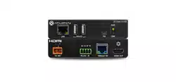
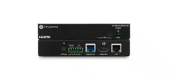
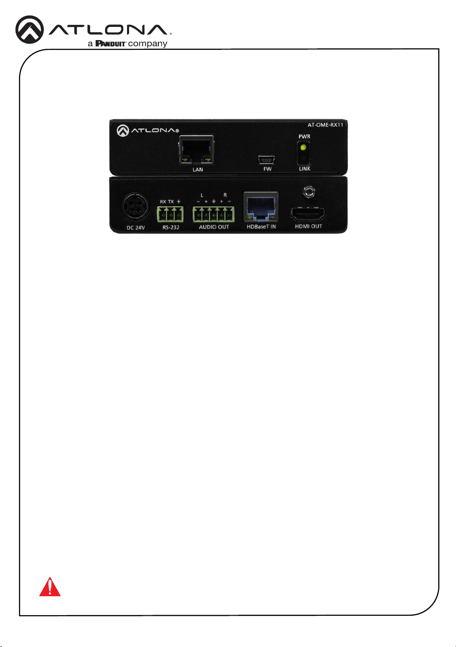
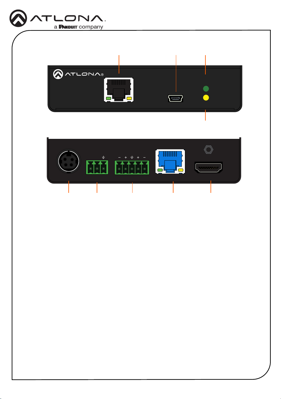
Panel Descriptions
1 LAN
Connect an Ethernet cable to this port
to pass Ethernet to a local device from a
transmitter or from a local network switch
to a compatible transmitter.
2 FW
Connect to a computer using a mini USB
to USB A cable (not included).
3 PWR LED
Illuminates green when receiving power.
4 LINK LED
Illuminates yellow when receiving signal
from the HDBaseT input port.
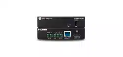
5 DC 24V
Connect the included DC 24V power
supply to this port.
6 RS-232
Bi-directional port for pass through
display control from/to a compatible
transmitter.
7 AUDIO OUT
Connect to an audio DSP, amplier, or
other audio distribution devices.
8 HDBaseT OUT
Connect a compatible HDBaseT
transmitter to this port.
9 HDMI IN
Connect an HDMI cable from here to an
HDMI source.
LAN FW
PWR
LINK
AT-OME-RX11
HDMI OUTHDBaseT INAUDIO OUTRS-232DC 24V
L R
RX TX
AT-OME-RX11
LAN FW
PWR
LINK
AT-OME-RX11
HDMI OUTHDBaseT INAUDIO OUTRS-232DC 24V
L R
RX TX
AT-OME-RX11
1 2 3
5
4
9
8
6
7
Installation Guide
3
AT-OME-RX11
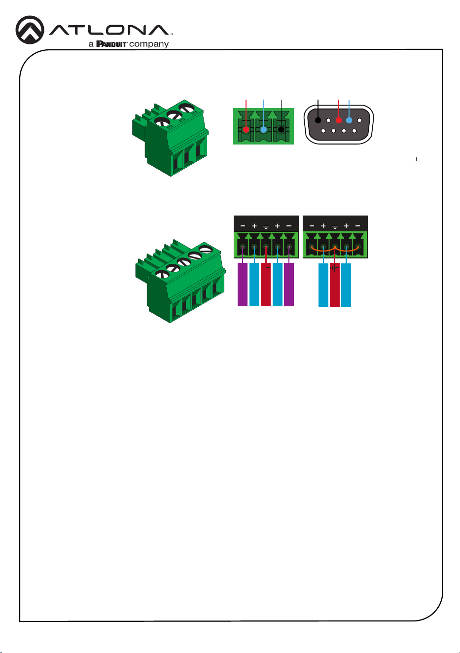
Audio
Deembeds audio and sends to a connected
audio DSP, amplier, or other audio distribution
devices.
RS-232
Use a jumper between the negative and ground
pins when using an unbalanced connection.
Balanced
Unbalanced
ANALOG IN
L R
Negative
-
Negative
-
+
Positive
+
Positive
Ground
ANALOG IN
L R
+
Positive
+
Positive
Ground
A 3-pin captive screw connector has been
included for RS-232.
Pin out will be determined by the RS-232 cable
and connect as RX (receive), TX (transmit) and
(Ground).
GND RX
TX
GNDRX TX

Installation Guide
4
AT-OME-RX11
5. Mount the unit using the oval-shaped holes, on each mounting bracket. If using a drywall
surface, a #6 drywall screw is recommended.
NOTE: Mounting brackets can also be inverted to mount the unit under a table
or other at surface.
Mounting Instructions
The AT-OME-RX11 includes two mounting brackets and four mounting screws, which can be
used to attach the units to any at surface.
1. Remove the top 2 case screws on the side of the unit.
2. Align the mounting brackets to the side of the units.
3. Use the previously removed case screws to secure the mounting bracket to the enclosure.
4. Repeat the steps for the other side of the unit.
FW
AT-HDR-EX-70C-RX
POWER
LINK
AT-OME-RX11
PWR
LINKFW
LAN
Included screws
FW
AT-HDR-EX-70C-RX
POWER
LINK
AT-OME-RX11
PWR
LINKFW
LAN
Installation Guide
5
AT-OME-RX11
1. Connect a compatible HDBaseT transmitter (e.g. AT-OME-ST31 or AT-OME-EX-TX) to the
HDBaseT input port using a category cable.
2. Connect an HDMI cable from the output port to an HDMI display.
3. *Optional* Connect the 2CH analog AUDIO OUT port to a DSP, or audio amplier.
4. *Optional* Connect to the 3-pin captive screw RS-232 port to control the display or send
commands back to the compatible transmitter over HDBaseT.
5. *Optional* Connect an Ethernet cable to the LAN port to pass or receive Ethernet. This can
be connected to a display if receiving Ethernet from a compatible transmitter or to a network
switch if sending Ethernet to a compatible transmitter.
6. Connect the included DC 24V power supply to the power port.
7. Connect the included IEC power cord from the power supply to a compatible power outlet.
Installation
Refer to the tables below for recommended cabling when using Altona products with HDBaseT.
The green bars indicate the signal quality when using each type of cable. Higher-quality signals
are represented by more bars.
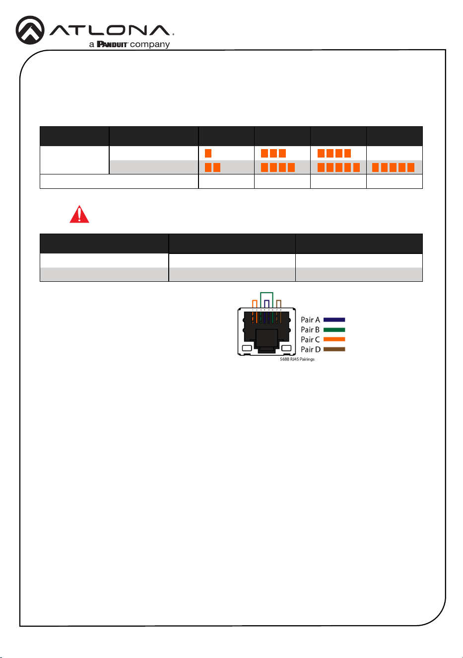
Cable Recommendation Guidelines
Core Shielding CAT5e CAT6 CAT6a CAT7
Solid UTP (unshielded) N/A
STP (shielded)
Performance Rating (MHz) 350 500 600 800
Use of a TIA/EIA 568B termination is
recommended for optimal performance.
Cable Max. Distance @ 4K Max. Distance @ 1080p
CAT5e 295 feet (90 meters) 330 feet (100 meters)
CAT6 / CAT6a / CAT7 330 feet (100 meters) 330 feet (100 meters)
IMPORTANT: Stranded or patch cables are not recommended due to
performance issues.
Installation Guide
6
AT-OME-RX11
Requirements:
• AT-OME-RX11
• Firmware le
• Computer running Windows
• USB-A to USB mini-B cable
1. Disconnect power from the AT-OME-RX11.
2. Connect a USB-A to USB mini-B cable between the PC and the FW port on the AT-OME-
RX11.
3. Connect the included power supply to the AT-OME-RX11.
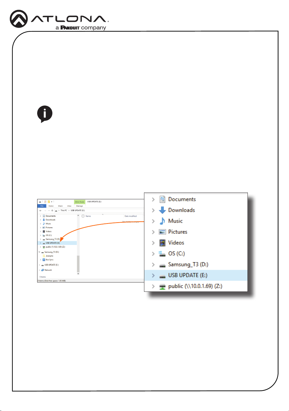
4. The USB UPDATE folder will be displayed. If this folder is not displayed, automatically,
select the USB UPDATE drive from Windows Explorer.
NOTE: The update process can take up to ve minutes to complete.
5. Delete all les from the USB UPDATE drive, if any are present.
6. Drag-and-drop the rmware le to the drive.
7. The PWR LED indicator, on the front panel, will ash green while the AT-OME-RX11 is being
updated. Do not disconnect the USB cable during the update process. When the PWR
LED stops ashing and is solid green, the update process will be complete.
8. Disconnect the USB cable from the AT-OME-RX11.
Updating the Firmware

Installation Guide
7
AT-OME-RX11
Notes
Installation Guide
8
AT-OME-RX11
Version 5 25118-R5
®
The terms HDMI, HDMI High-Denition Multimedia Interface, and the HDMI Logo are trademarks or
registered trademarks of HDMI licensing Administrator, Inc.
© 2022 Atlona Inc. All rights reserved. “Atlona” and the Atlona logo are registered trademarks of Atlona Inc. All other brand names and trademarks or registered
trademarks are the property of their respective owners. Pricing, specications and availability subject to change without notice. Actual products, product images, and
online product images may vary from images shown here.
US International
atlona.com • 408.962.0515 • 41.43.508.4321
English Declaration of Conformity
The English version can be found under the resources tab at:
https://atlona.com/product/at-ome-rx11/.
Warranty
Chinese Declaration of Conformity 中国RoHS合格声明
To view the product warranty, use the following link or QR code:
https://atlona.com/warranty/.
由SKU列出於:
https://atlona.com/about-us/china-rohs/.