
Ciclomotor/Moped
Manual de instrucciones
Instruction manual
Manuel d’instructions
Bedienungsanleitung
Manuale di istruzioni
Manual de instruções
Instructiehandleiding
Instrukcja obsługi
Návod k použití
MAKALU PRO

6564
MAKALU PRO
ENGLISHESPAÑOL
8. RECICLAJE DE APARATOS ELÉCTRICOS Y ELECTRÓNICOS
Este símbolo indica que, de acuerdo con las normativas aplicables, el
producto y/o la batería deberán desecharse de manera independiente de los
residuos domésticos. Cuando este producto alcance el nal de su vida útil,
deberás extraer las pilas/baterías/acumuladores y llevarlo a un punto de
recogida designado por las autoridades locales.
Para obtener información detallada acerca de la forma más adecuada de
desechar sus aparatos eléctricos y electrónicos y/o las correspondientes
baterías, el consumidor deberá contactar con las autoridades locales.
El cumplimiento de las pautas anteriores ayudará a proteger el medio
ambiente.
9. GARANTÍA Y SAT
Cecotec responderá ante el usuario o consumidor nal por las faltas de conformidad que
existan en el momento de la entrega del producto en los términos, condiciones y plazos
establecidos por la normativa aplicable.
Se recomienda que las reparaciones sean realizadas por personal cualicado.
Si detecta una incidencia con el producto o tiene alguna consulta, póngase en contacto con el
Servicio de Asistencia Técnica ocial de Cecotec a través del número de teléfono +34 96 321
07 28.
10. COPYRIGHT
Los derechos de propiedad intelectual sobre los textos de este manual pertenecen a CECOTEC
INNOVACIONES, S.L. Quedan reservados todos los derechos. El contenido de esta publicación no
podrá, ni en parte ni en su totalidad, reproducirse, almacenarse en un sistema de recuperación,
transmitirse o distribuirse por ningún medio (electrónico, mecánico, fotocopia, grabación o
similar) sin la previa autorización de CECOTEC INNOVACIONES, S.L.
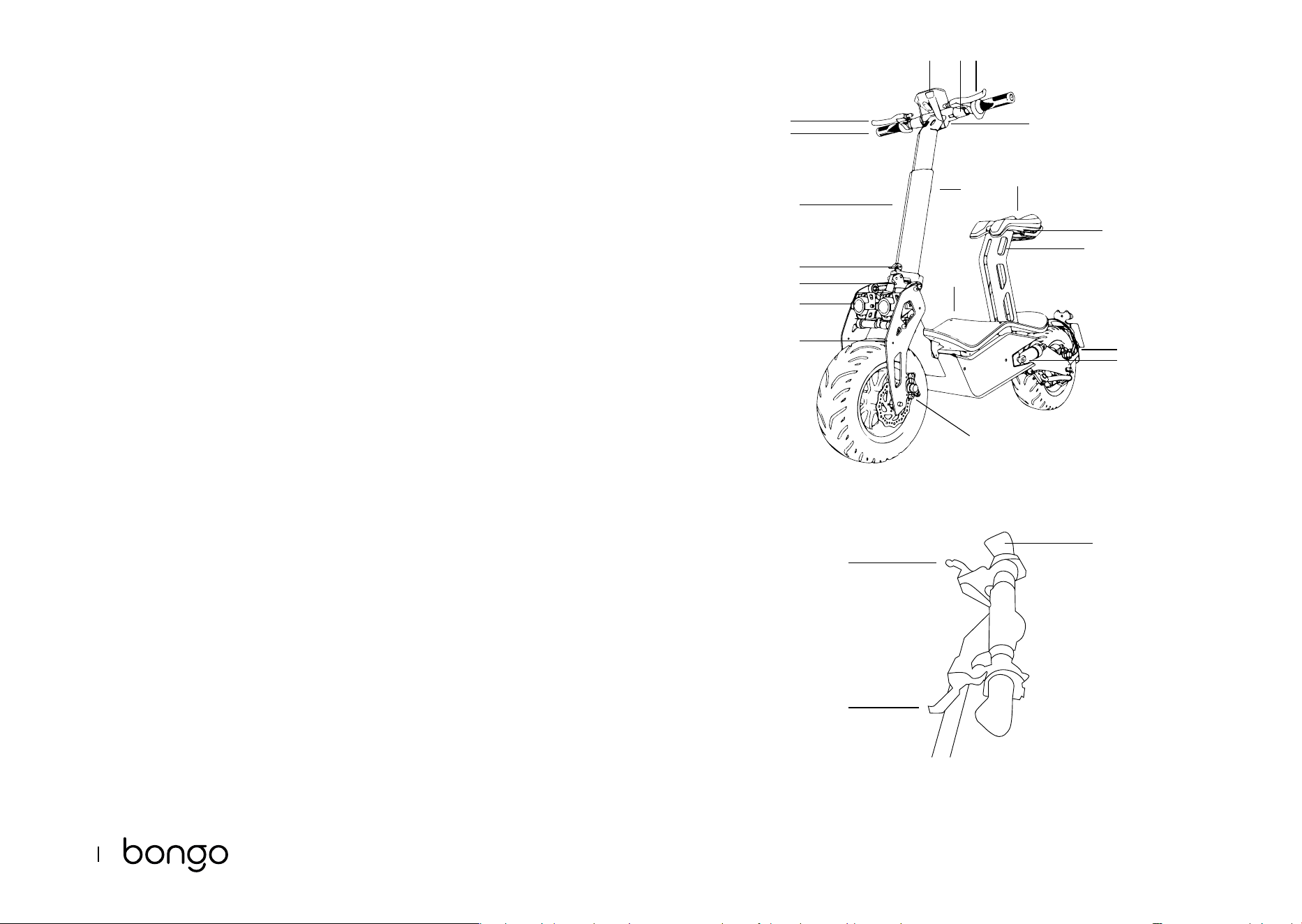
1. PARTS AND COMPONENTS
Fig. 1
1. Key switch
2. Handlebar height adjustment knob
3. Throttle
4. Rear-brake lever
5. Front-brake lever
6. Handlebar xing lever
7. Deck
8. Front damper
9. Rear damper
10. Saddle
11. Front brake calliper
12. Brake calliper
13. Handlebar stem
14. Saddle heigh adjustment lever
15. Handlebar
16. Headlight (approved for road trac)
17. Taillight (approved for road trac)
18. Horn (approved for road trac)
19. Speedometer (approved for road trac)
Fig. 2
1 Throttle
2 Front-brake lever
3 Rear-brake lever
Note:
The graphics in this manual are schematic representations and may not exactly match the
device.
2. BEFORE USE
- This moped comes in a packaging designed to protect it during transport. Take the moped
out of the box and remove all packaging materials. You can keep the original box and other
packaging elements in a safe place. This will help you prevent damage to the device when
transporting it in the future. In case the original packaging is disposed of, make sure all
packaging materials are recycled accordingly.
- Make sure all parts and components are included and in good conditions. If there is any

6766
MAKALU PRO
ENGLISH ENGLISH
piece missing or not in good condition, immediately contact the ocial Cecotec Technical
Support Service.
Box content:
- Makalu Pro
- Tool kit
- Instruction manual
- 20 A fuse
- Saddle and saddle post
- Headlight (approved version)
- Taillight (approved version)
- Horn (approved version)
- Speedometer (approved version)
- Carry bag (optional)
- Instruction manual
3. ASSEMBLY
Unfolding the handlebar. Fig. 3
1 The vehicle is delivered folded and with the handlebars removed.
2 First, unscrew washer 1 and remove screw 2.
3 Position the handlebar and insert screw 2 with locknut 1.
4 To place the handlebar stem properly in position, raise the handlebar and press closing
spring 3.
5 Insert the locking lever into the corresponding slot and turn until properly locked.
NOTE: to fold the handlebar again, follow the reverse the procedure.
Assembling the handlebar grips. Fig. 4-5
With the handlebar upright, the grips will remain suspended as shown in Figure 4.
1 Take the left grip and pull it upwards until pushed into position.
2 Repeat the above step with the right grip.
Adjusting the handlebar height. Fig. 6
1 Turn the adjustment knob counterclockwise and adjust the handlebar to the desired height.
2 Once set to the desired height, turn the adjustment knob clockwise to lock it in place. Make
sure the handlebar is rmly xed.
Battery and motor
Both the battery and the motor come already installed and connected. To access any of these
parts, lift the deck. To activate the electrical circuit, install the fuse provided.
Installing the saddle. Fig. 7
1 Insert the saddle into the saddle post tting it snugly into the groove.
2 Screw the saddle in position on each side until completely xed.
Adjusting the height of the saddle
To adjust the saddle height, unlock lever 1 and lower or raise the saddle to the desired position.
Once the saddle is set to the desired height, lock lever 1 again.
Adjusting the front and rear brakes. Fig. 8
- Both brakes require periodic adjustment.
- The brakes should be about 5-6 mm away from the handlebar grip.
- Stand on the vehicle to check the distance between the handlebar grip and the brake. If the
brakes exceed the recommended distance, turn the brake washer (A) to adjust it.
- To adjust the brake cable tension, adjust the screw (B) on the rear wheel. This will allow the
wheel to turn easily when the brake is not being used and will also immediately bring the
vehicle to a stop when the brake lever is pressed.
WARNING: after each adjustment, tighten the locknut.
Vehicle approval
To register this vehicle for use in public spaces, you must:
- Consult the legal regulations in force in your region.
- Carry out the assembly described below.
- Contact [email protected] and provide the following information:
- Full name of the vehicle owner.
- ID of the vehicle owner.
- Chassis number located on the plate riveted to the chassis on the right side of the
latter and laser engraved on the left side.
- Purchase invoice.
When driving your vehicle in public areas, we recommend you consult the legal regulations in
force in your region and carry the following documents:
- ID
- Warranty
- Technical data sheet
- Road tax
- Registration certicate
Assembling the approval kit.
Parts and components. Fig. 9
1 Saddle post
2 Saddle

6968
MAKALU PRO
ENGLISH ENGLISH
3 Headlight bracket
4 Speedometer bracket
5 Speedometer
6 Rear fender
7 Number-plate holder swingarm
8 Tool kit
9 Rearview mirrors
10 Number-plate holder with built-in light
3.1. Mounting the headlight
- Headlights come installed by default as shown in Figure 10.
- To install the headlights in the correct position, rst loosen the screws marked 6 and
remove them. Then use 4 M6 * 16 hex screws and 4 ange lock nuts to x the headlight
bracket, and mount the headlights on the bracket as shown in Figure 10. B
Warning: some of the headlight parts have no use and must be removed. Please remove the
parts shown in Figure 11.
3.2. Mounting the swingarm for the number-plate holder with built-in light Fig. 12
- To t the number-plate holder swingarm, add a hub and replace both screws.
- Replace the screws marked 7 and 8 with 2 M6*30 hex screws.
- Then connect the light cable from the number-plate holder to the cable of the moped post.
3.3. Mounting the rearview mirrors. Fig. 13
To install the rearview mirrors, simply insert them in the handlebar holes and screw them
securely in place. Once xed, cover the lower part with the trim piece.
3.4. Mounting the speedometer. Fig. 14-15
To install the speedometer, rst mount the speedometer bracket on the handlebars. To do this,
screw 2 M6*10 hex screws into the threaded holes at the rear of the handlebar as shown in
Figure 14. Then use 2 M4*10 hex screws to x the speedometer to the bracket.
4. OPERATION
Charging the battery. Fig. 16
WARNING: make sure the device is switched o.
1 Open the charging port cover (1) on the right side of the vehicle and insert the end of the
adapter.
2 Connect the other end of the power cable to a plug socket. The indicator light will turn red
during charging and will change to green once charge is complete.
NOTE:
- The device comes pre-charged. However, it is recommended to charge it for 6 to 8 hours
before rst use.
- It is also recommended to charge it after every use and before storage.
- Do not allow the vehicle to fully run out of battery to prevent damage to the latter.
Start-up. Fig. 17
Insert the key and turn it clockwise to start the vehicle.
Throttle and brakes. Fig. 18
The throttle and front brake are located on the right handlebar grip.
1. Turn the throttle towards you to accelerate and release to decelerate.
2. Press the brake lever on the right side of the handlebar to brake with the front wheel.
3. The rear-brake lever is located on the left side of the handlebar. Press the left brake lever
to brake with the rear wheel.
WARNING: do not turn the throttle abruptly. Turn it slowly to avoid accidents.
5. CLEANING AND MAINTENANCE
Cleaning
- Clean the vehicle with a soft cloth, water, and soap if necessary.
- After cleaning it, thoroughly dry any metal parts that may corrode or rust.
- Grease the suspension pivot points.
General maintenance
- Maintenance tasks must always be carried out by qualied personnel.
- Always use original Cecotec spare parts.
- Lower the kickstand and switch o the vehicle before carrying out any type of repair.
Tests to carry out
- After a fall, check that the throttle grip is working properly. To do this, try accelerating and
decelerating several times.
- Regularly check that the brakes are in proper working condition. To do this, move the
vehicle by pushing it manually and brake suddenly to make sure it responds.
- Check that all vehicle parts are in position and securely fastened.
- Check the screws.
- Check wheel wear and tension.
- Check the brakes and throttle cables for wear.
7170
MAKALU PRO
ENGLISH ENGLISH
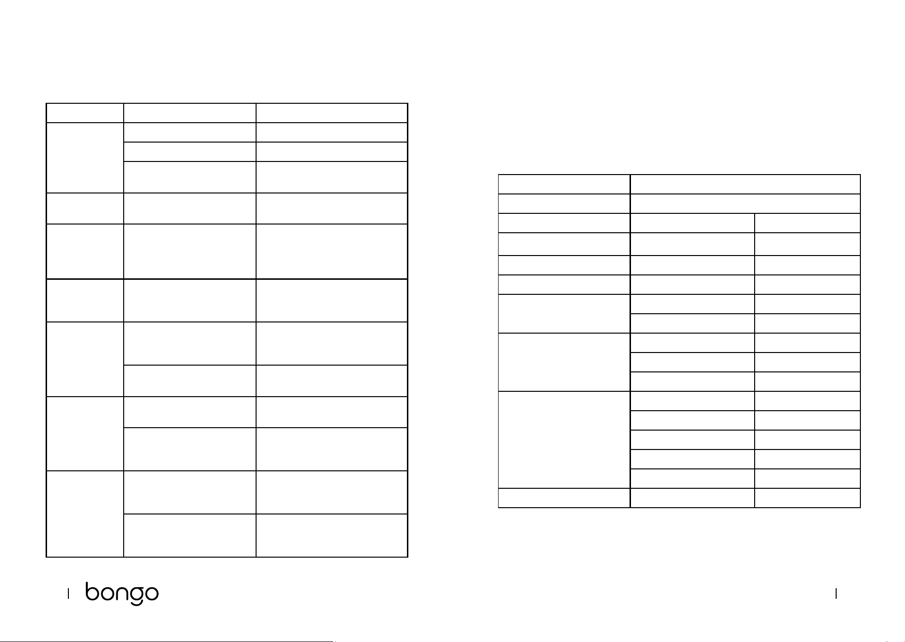
6. TROUBLESHOOTING
Error Possible cause Possible solution
The motor does
not start.
The battery is not connected. Check the cables.
Low battery. Charge the battery.
Electrical fault. Check all cables: contact the ocial
Cecotec Technical Support Service.
The rear wheel
does not turn.
Motor fault. Check the motor: contact the ocial
Cecotec Technical Support Service.
The motor
turns o during
operation.
Tripped dierential circuit. Release the throttle and wait until
the motor cools down.
Contact the ocial Cecotec
Technical Support Service.
The vehicle
turns o after
recharge.
The battery is not fully
charged.
Charge the battery.
Battery fault. The battery has reached the
end of its useful life or is not
functioning properly.
Replace the battery: contact the
ocial Cecotec Technical Support
Service.
The battery is frozen. Place the battery in a warm
environment until it stabilises.
The vehicle
stops suddenly
during operation.
Fuse fault. Replace the fuse: contact the ocial
Cecotec Technical Support Service.
The cable is damaged. Check and repair or replace the
cable: contact the ocial Cecotec
Technical Support Service.
The battery does
not charge.
Low battery. Replace the battery: contact the
ocial Cecotec Technical Support
Service.
The charger is broken. Check and repair or replace the
cable: contact the ocial Cecotec
Technical Support Service.
Note:
If none of these situations match your problem, do not attempt to disassemble or repair the
device by yourself. Repairs carried out by unqualied persons may result in injury or serious
malfunctions. Contact the ocial Cecotec Technical Support Service. The repair must be carried
out by an authorised technician and you must use only original spare parts.
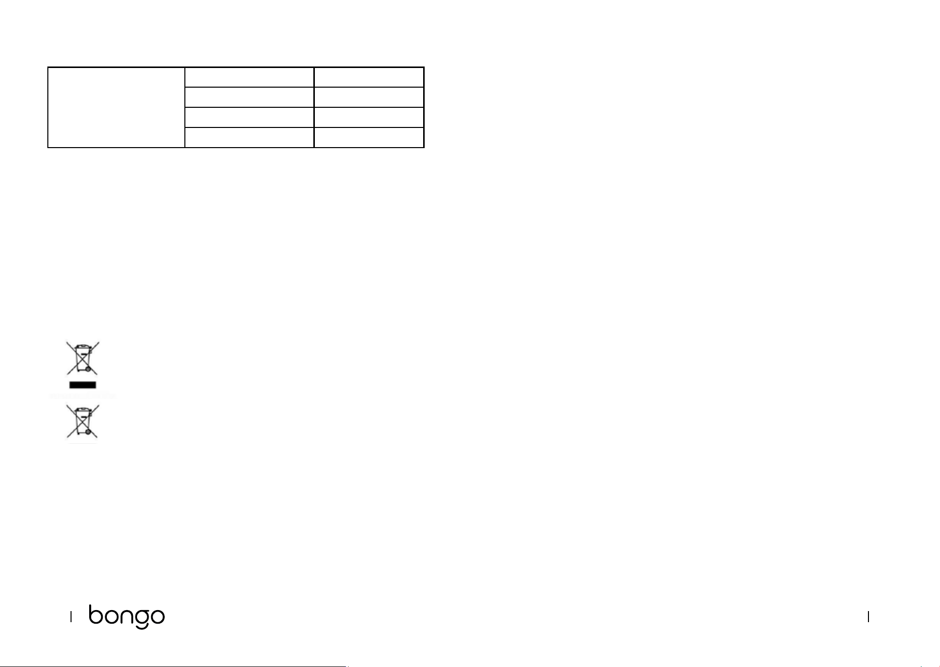
7. TECHNICAL SPECIFICATIONS
Product reference: 07320
Product: Makalu Pro electric moped
Features Measuring units Specications
Dimensions Length x Width x Height (1) 1350 x 630 x 1080 mm
Weight Moped weight 54 kg
User requirements
Age bracket (2) AM license
Technical specications Range (3) 45 Km
Max. speed 45 km/h
Motor Max. power 1600 W
Rated power 1000 W
Par 54 N*m
Battery
Charging time 6 h
Capacity: 20 Ah
Rated voltage 48 V
Max. charge voltage 54.6 V
Max. charging current 2 A
Wheels Wheel 135/65-8
7372
MAKALU PRO
ENGLISH ENGLISH
Charger Model GJS150-5760200
Inlet 100-240 V ~ 50/60 Hz
Outlet 57.6 V - 2 A
Protection IP20
(1) Height from the oor to the upper part of the handlebar.
(2) Check the current local regulations.
(3) Measured with a weight of 80 kg, fully charged battery, at surface, no inclination, no wind,
and an ambient temperature of approximately 25 °C.
- The total value of the exposed vibration in the hand-arm system does not exceed 2.5 m/s
2
.
- The weighted acceleration to which the whole body is submitted does not exceed 0.5 m/s
2
.
- The A-weighted emission sound pressure level at work stations is less than or equal to
70 dB.
Technical specications may change without prior notice to improve product quality.
Made in China | Designed in Spain
8. DISPOSAL OF OLD ELECTRICAL AND ELECTRONIC APPLIANCES
This symbol indicates that, according to the applicable regulations, the
product and/or batteries must be disposed of separately from household
waste. When this product reaches the end of its shelf life, you should dispose
of the batteries/accumulators and take them to a collection point designated
by the local authorities.
For detailed information on the most appropriate way to dispose of electrical
and electronic equipment and/or batteries, consumers should contact their
local authorities.
Compliance with the above guidelines will help protecting the environment.
9. TECHNICAL SUPPORT AND WARRANTY
Cecotec shall be liable to the end user or consumer for any lack of conformity that exists at the
time of delivery of the product under the terms, conditions, and deadlines established by the
applicable regulations.
It is recommended that repairs are carried out by qualied personnel.
If at any moment you detect any problem with your product or have any doubt, do not hesitate
to contact the ocial Cecotec Technical Support Service at +34 963 210 728.
10. COPYRIGHT
The intellectual property rights over the texts in this manual belong to CECOTEC INNOVACIONES,
S.L. All rights reserved. The contents of this publication may not, in whole or in part, be
reproduced, stored in a retrieval system, transmitted, or distributed by any means (electronic,
mechanical, photocopying, recording or similar) without the prior authorization of CECOTEC
INNOVACIONES, S.L.
136
ČEŠTINA
9. ZÁRUKA A TECHNICKÝ SERVIS
Společnost Cecotec odpovídá uživateli nebo konečnému spotřebiteli za jakýkoli nesoulad,
který existuje v době dodání výrobku za podmínek a ve lhůtách stanovených platnými předpisy.
Doporučuje se, aby opravy prováděl kvalikovaný personál.
Pokud zjistíte problém s výrobkem nebo máte jakékoli dotazy, obraťte se na ociální technickou
podporu společnosti Cecotec na čísle +34 96 321 07 28.
10. COPYRIGHT
Práva duševního vlastnictví k textům v této příručce patří společnosti CECOTEC INNOVACIONES,
S.L. Všechna práva jsou vyhrazena. Obsah této publikace nesmí být, zčásti nebo jako celek,
reprodukován, ukládán do systému obnovy, přenášen nebo distribuován žádnými prostředky
(elektronicky, mechanicky, foto kopírováním, nahráváním nebo podobným způsobem) bez
předchozího souhlasu společnosti CECOTEC INNOVACIONES, S.L.
Fig./Img./Abb./Afb./ Rys./Obr. 1
Fig./Img./Abb./Afb./ Rys./Obr. 2
1
2
2
10
7
6
8
16
18
13
17
14
9
12
11
419 15
3
1
3
5
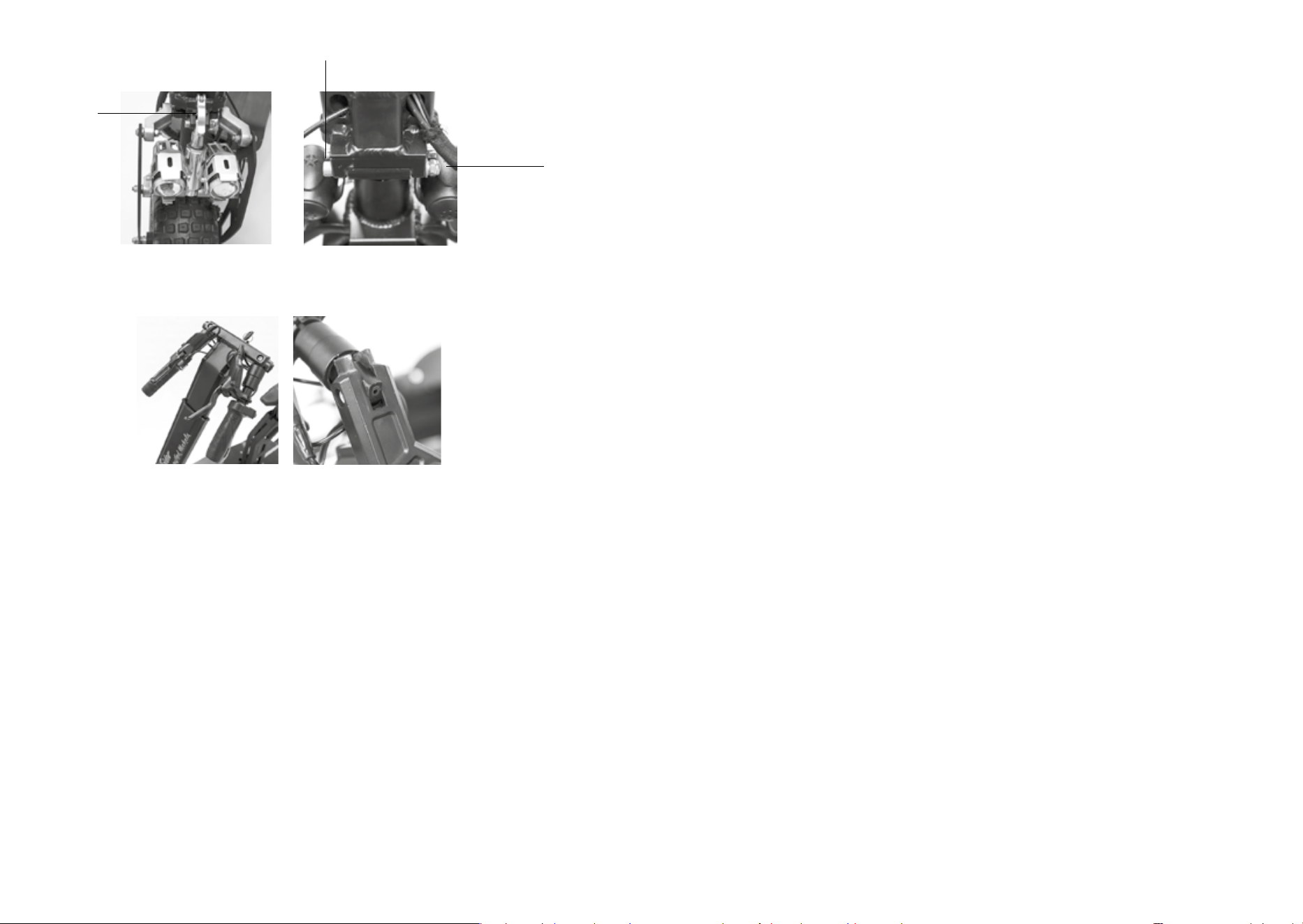
Fig./Img./Abb./Afb./ Rys./Obr. 3
Fig./Img./Abb./Afb./ Rys./Obr. 4
Fig./Img./Abb./Afb./ Rys./Obr. 5
Fig./Img./Abb./Afb./ Rys./Obr. 6 Fig./Img./Abb./Afb./ Rys./Obr. 7
Fig./Img./Abb./Afb./ Rys./Obr. 8
Fig./Img./Abb./Afb./ Rys./Obr. 9
1
1
6
2
7
3
8
4
9
5
10
2
3

Fig./Img./Abb./Afb./ Rys./Obr. 10.A Fig./Img./Abb./Afb./ Rys./Obr. 10.B
Fig./Img./Abb./Afb./ Rys./Obr. 11
Fig./Img./Abb./Afb./ Rys./Obr. 12
Fig./Img./Abb./Afb./ Rys./Obr. 13
Fig./Img./Abb./Afb./ Rys./Obr. 14
Fig./Img./Abb./Afb./ Rys./Obr. 15

Fig./Img./Abb./Afb./ Rys./Obr. 18
Fig./Img./Abb./Afb./ Rys./Obr. 16
Fig./Img./Abb./Afb./ Rys./Obr. 17

www.cecotec.es
Cecotec Innovaciones S.L.
Av. Reyes Católicos, 60
46910, Alfafar , Valencia (Spain)
YV_02230306