18
(4x)
75
79
26
27
29
28
30
31
32
41
78
16
15
(3x)
77
14
13
10
9
7
5
6(2x)
8
69
68
80
84
63
35(2x)
36(2x)
53
56
47
55
59
58
57(2x)
52
(2x)
61
60
49
51
70
50
(5x)
67
40
48
27
28
81
63
82
4
3
2
(2x)
1
(2x)
1 2 3
4 5 6
7 8 69
83
1 2
4 7
8 69
85
40 48
52 53
55 56
76
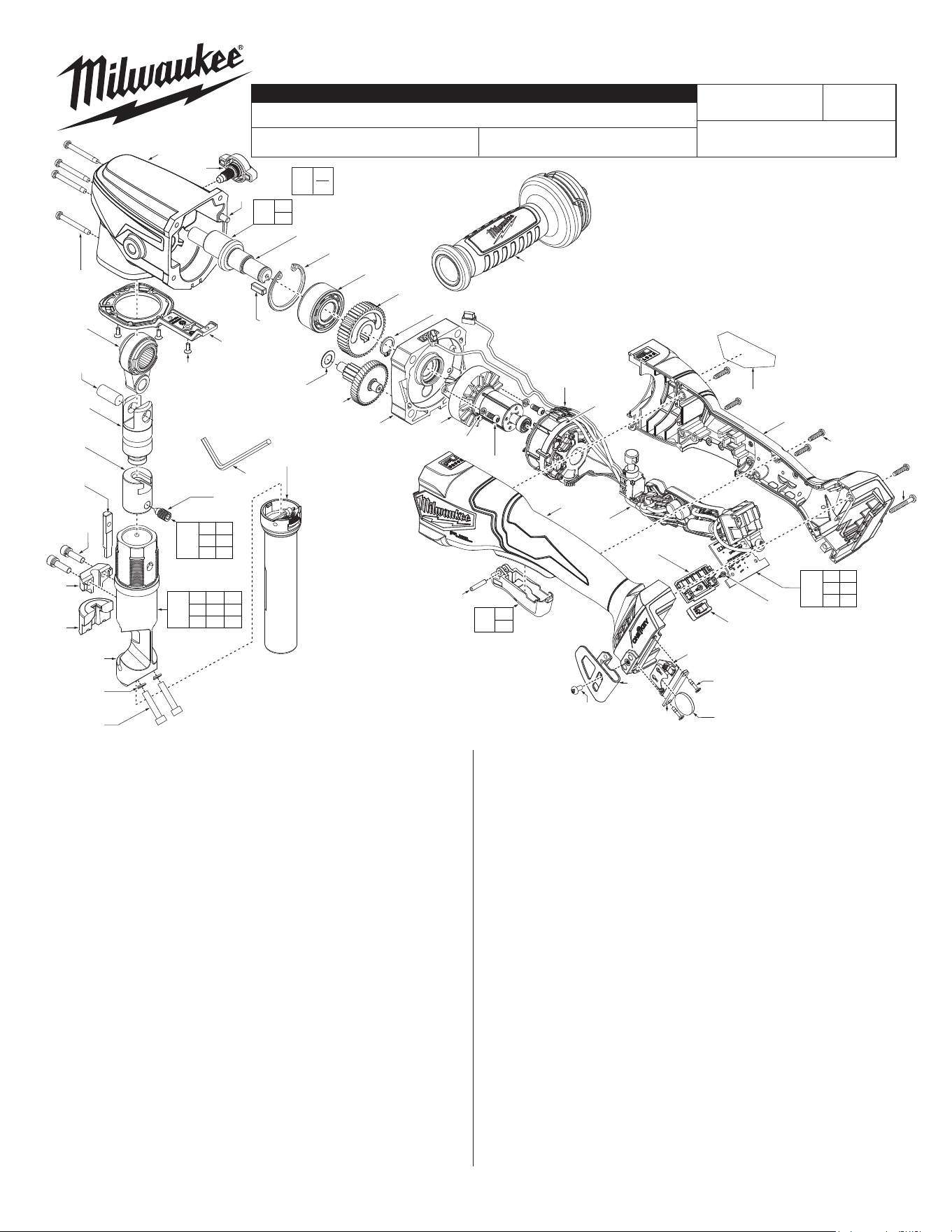
FIG. PART NO. DESCRIPTION OF PART NO. REQ.
1 --------------- M5 x 25mm CH Hex Mach. Screw (2)
2 --------------- Spring Washer (2)
3 --------------- Die Holder (1)
4 --------------- Die (1)
5 --------------- Punch Guide (1)
6 --------------- M5 x 25mm CH Hex Screw w/Washer (2)
7 --------------- Die (1)
8 05-74-7215 M8 x 18 Set Screw (1)
9 43-72-7175 Punch Holder (1)
10 44-66-7370 Piston (1)
13 06-65-7575 Piston Pin (1)
14 42-62-0125 Side Handle (1)
15 05-74-7220 M3 x 0.5 FH Philips #2 Screw (3)
16 31-15-2735 LED Cover (1)
18 06-82-4002 M4 x 1.411 PH T-20 Screw (4)
26 --------------- Locating Pin (1)
27 --------------- Eccentric Shaft (1)
28 --------------- Square Key (1)
29 34-80-2275 Retaining Ring (1)
30 02-04-7235 Ball Bearing (1)
31 32-75-5385 2nd Layer Gear (1)
32 34-80-0002 Retaining Ring (1)
35 05-90-0225 Spring Washer (2)
36 05-78-0105 M4 x 0.7 PH T-20 Taptite Screw (2)
40 --------------- Stator (1)
41 45-88-1766 Washer (1)
47 31-15-2740 Coin Cell Cover (1)
48 --------------- Motor Stator Adapter (1)
49 31-44-7275 Handle Cover (1)
MILWAUKEE TOOL
l
www.milwaukeetool.com
13135 W. LISBON RD., BROOKFIELD, WI 53005
Drwg. 1
0
00
EXAMPLE:
Component Parts (Small #)
Are Included When Ordering
The Assembly (Large #).
50 05-81-5383 M3.5 x 14mm CH Screw (5)
51 06-82-2025 M3.5 x 26mm Screw (1)
52 05-88-0106 M2 x 0.89 Screw (6)
53 --------------- PCB Assembly (1)
55 45-24-2570 Mode Selector Button (1)
56 --------------- Mode Select Panel (1)
57 05-80-0433 M2.6 x 0.907 Flat Hd. Philips Screw (2)
58 --------------- Coin Cell Battery (CR2032) (1)
- See local hardware store
59 22-09-6635 Coin Cell Board (1)
60 42-70-5151 Belt Hook (1)
61 06-82-2500 #6-32 Pan Hd. T-15 Screw (1)
63 --------------- Trigger Pivot Post (1)
67 31-50-2405 Handle Support (1)
68 42-16-2725 Chip Collection Bag Assembly (1)
69 45-96-8001 Hex Key (1)
70 12-20-3476 Service Nameplate (1)
75 14-30-6340 Gearcase Assembly (1)
76 22-09-1885 PCBA/Stator Assembly (1)
77 14-09-2825 Con Rod Assembly (1)
78 14-73-3285 Intermediate Shaft/First Gear Assembly (1)
79 14-20-7015 Wingnut/Washer/O-Ring Assembly (1)
80 44-66-7375 End Cap Assembly (1)
81 14-20-7020 Eccentric Shaft Service Kit (1)
82 31-92-1075 Trigger Cap Assembly (1)
83 48-44-0276 Die Holder Accessory Kit (1)
84 16-01-2790 Rotor Assembly (1)
85 48-44-0274 Punch & Die Accessory Kit (1)
BULLETIN NO.
PN0004203
SERVICE PARTS LIST
CATALOG NO. 3476-20
REVISED BULLETIN
SPECIFY CATALOG NO. AND SERIAL NO. WHEN ORDERING PARTS
M18 FUEL
™
10 Gauge Nibbler
SERIAL NO.
DATE
Dec. 2024
WIRING INSTRUCTION
R19A
See Page 3
FIG. PART NO. DESCRIPTION OF PART NO. REQ.
FIG. NOTES
70 A clean, dry surface is essential for
proper performance for any adhesive
system. The area intended for application
of any adhesive label or nameplate must
be prepared by cleaning with isopropyl
alcohol. The solvent is to be applied with
a clean, lint free applicator and the
surface allowed to dry before applying
the label or nameplate.
SCREW TORQUE SPECIFICATIONS
SEAT TORQUE
FIG. PART NO. WHERE USED (kgf-cm) (lb-in)
1 06-97-3610 Die Holder 85±5 74±4
6 06-83-0020 Punch Guide 85±5 74±4
8 05-81-0592 Punch Holder 65±5 56±4
15 43-98-0032 LED Cover 8±1 7±1
18 05-88-1255 Gearcase 16.5±1.5 14.3±1.3
23 05-88-1255 Wing Nut Assy. 30±2 26±2
36 --------------- Bearing Retainer 26±3 23±3
50 06-82-0062 Handle Housing 14.5±2 12.6±2
51 06-82-1087 Handle Housing 14.5±2 12.6±2
52 06-82-7210 Hall Sensor 3±0.5 3±0.4
57 06-82-7210 Coin Cell Cover 4.5±0.4 3.9±0.3
61 06-82-7210 Belt Hook 10.5±1.5 9.1±1.3
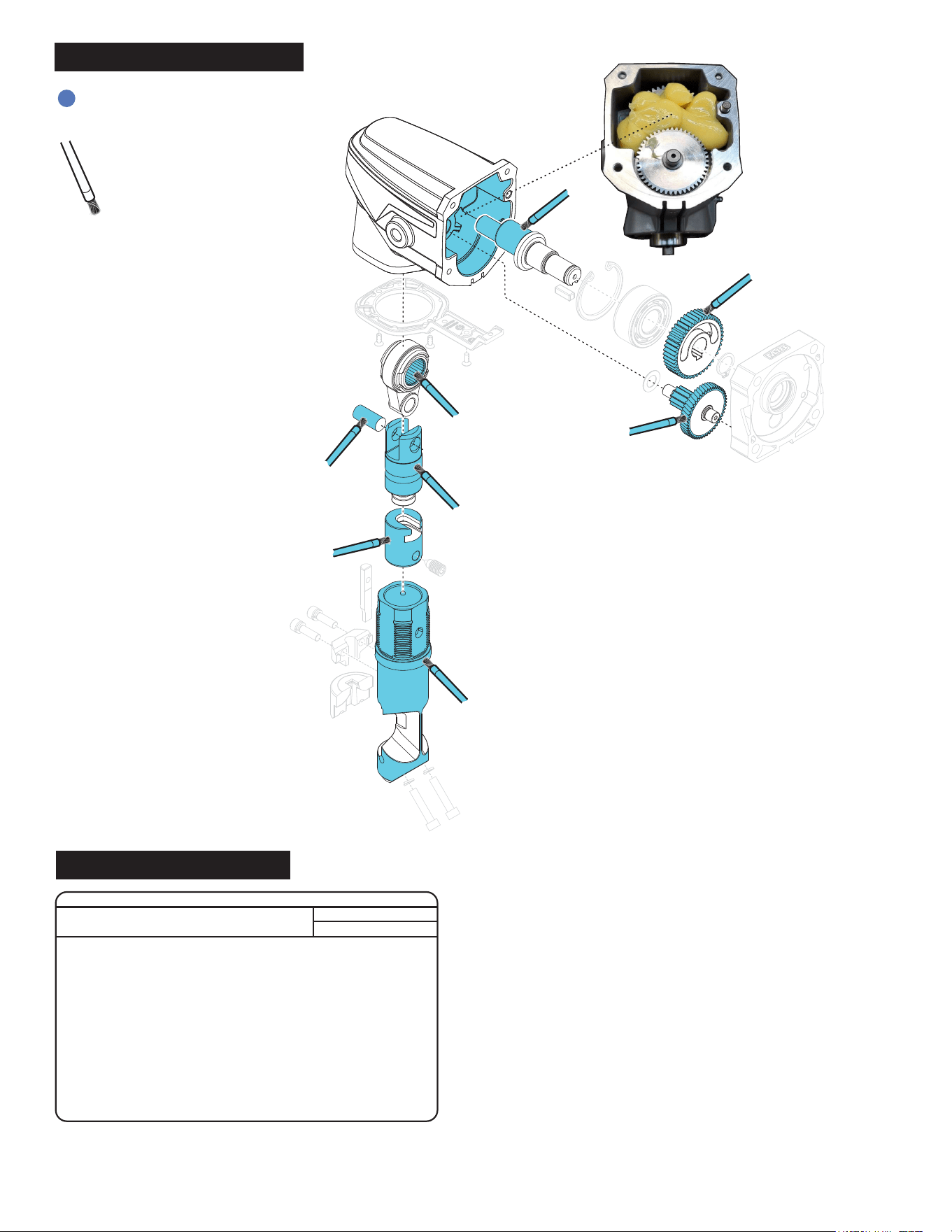
NOTE
When servicing, remove 90-95%
of the existing grease prior to
installing Type ‘J’. Original grease
may be similar in color but not
compatible with ‘J’.
Regarding parts to be lubricated:
Apply a light coating of grease to
all highlighted parts shown prior
to installation.
Add 39.5G of grease
after assembling all
geartrain parts inside
make sure the grease
is poured evenly inside
the gearcase
= Type ‘J’ Grease,
(1-lb. can), 49-08-4220
LUBRICATION INSTRUCTIONS
TORQUE SPECS
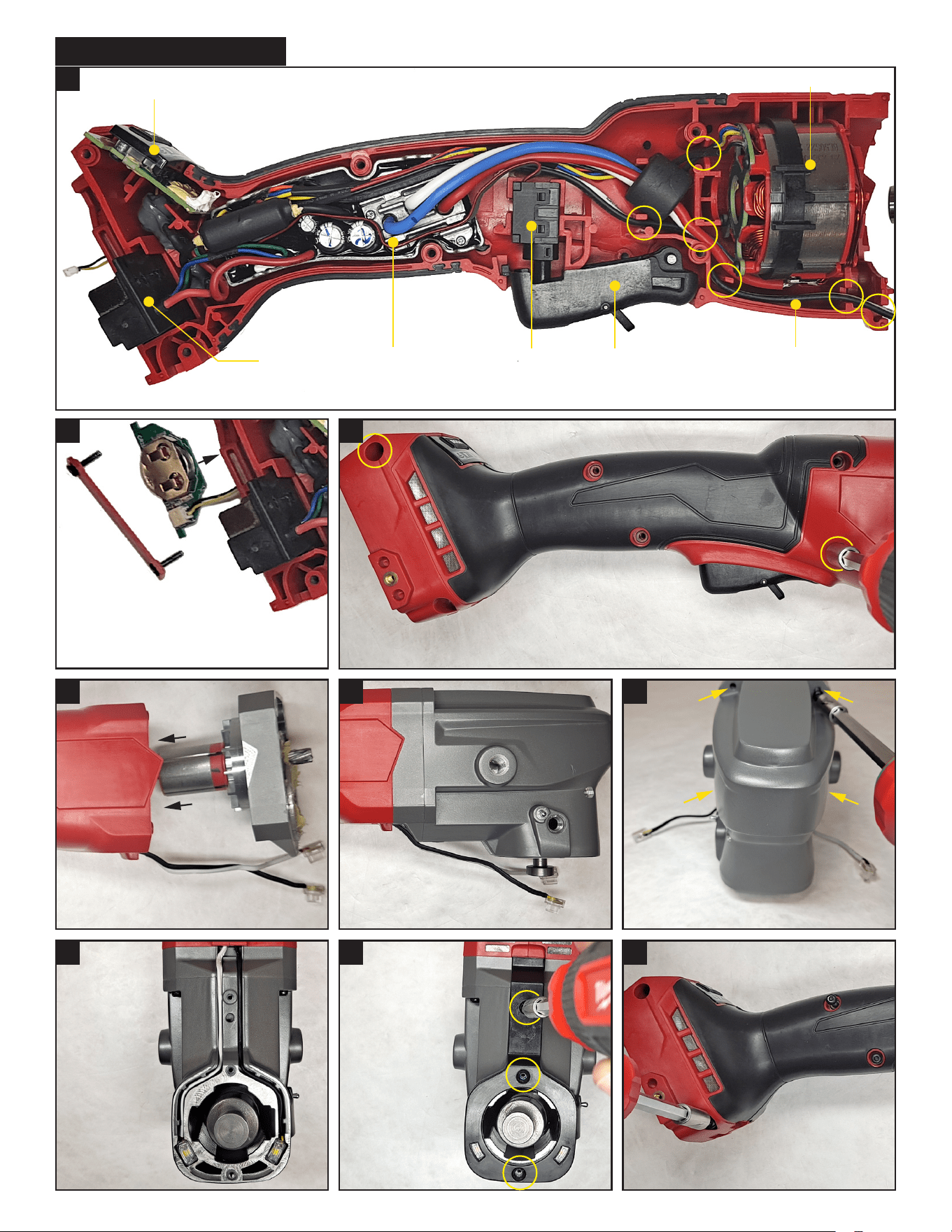
Stator (40)
Trigger
Switch
PCBA (53)
Battery
Terminal
Mode Selector
Button/Panel (55,56)
Assemble all components into slots of tool handle support. Route wires through proper channels and traps as shown above.
Trigger Cap
Assembly (82)
LED Light
Wires
After feeding coin cell board
connector through bottom slot,
connect to coin cell board (59), tuck wires
board into bottom opening and fasten coin
cell cover (47) with 2 screws (57).
Place handle cover (49) on top of support (67), making sure there are no
interferences. Fasten with 2 screws (50) in locations shown circled in yellow.
Fully insert rotor/endcap assembly
into stator within housing.
Place gearcase assembly
onto endcap assembly.
Fasten 4 screws (18) to attach gearcase
assembly to endcap/handle.
Route LED
lights/wiring
within the
channels on
the bottom of
the gearcase
assembly.
Fasten 3
screws (15)
to attach
LED cover
to gearcase
assembly.
Fasten remaining 4 screws (50,51)
to attach handle cover to support.
1
2 3
4 5 6
7 8 9
WIRING INSTRUCTIONS