
MILWAUKEE TOOL
l
www.milwaukeetool.com
13135 W. LISBON RD., BROOKFIELD, WI 53005
Drwg. 2
BULLETIN NO.
54-26-2760
SERVICE PARTS LIST
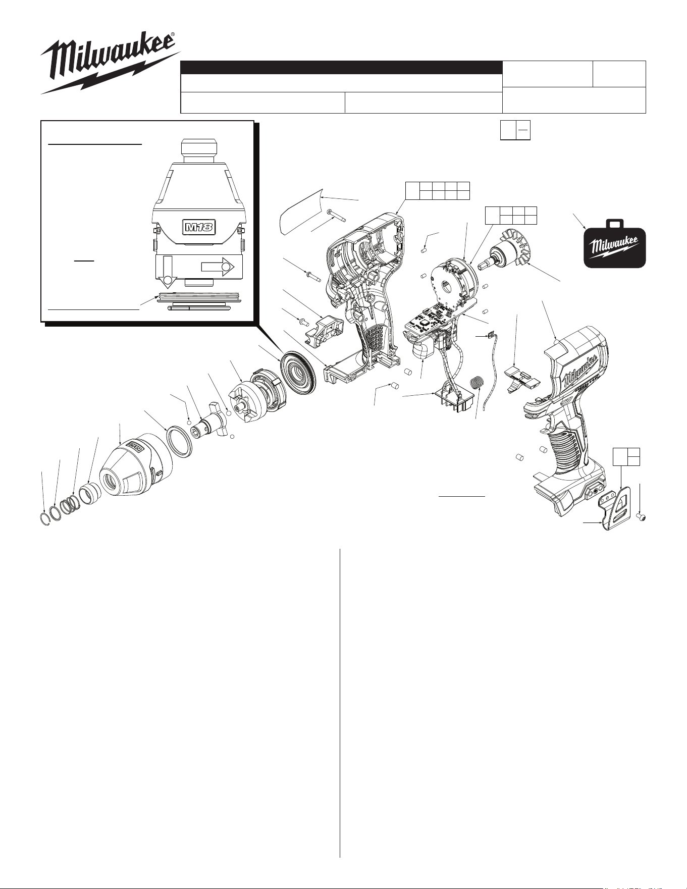
FIG. PART NO. DESCRIPTION OF PART NO. REQ.
1 34-60-0725 Retaining Ring (1)
2 45-88-2026 Washer (1)
3 40-50-1470 Spring (1)
4 45-22-2657 Sleeve (1)
8 45-88-2653 Plastic Washer (1)
9 02-02-1100 4.0mm Steel Ball (2)
10 42-06-2750 1/4" Hex Anvil (1)
11 02-02-1300 5mm Steel Ball (1)
24 44-66-0425 Gearcase End Cap with Ball Bearing (1)
25 06-82-7236 4-20 x .625 Pan Hd. Plast. T-10 Screw (8)
26 43-72-0550 Bit Holder (Optional) (1)
27 06-82-0130 6-32 x 5/16” Pan Hd. T-15 Screw (2)
28 --------------- Housing Cover - Right Housing Halve (1)
29 05-86-0300 M3.0 x 22.5mm Pan Hd. ST T-10 Screw (1)
31 45-30-1000 Rubber Slug (Battery area of housings) (4)
32 --------------- PCBA (1)
34 --------------- Stator Assembly (1)
35 42-42-0235 Forward/Reverse Shuttle (1)
36 45-30-2653 Rubber Slug (Stator area of housings) (4)
42 --------------- Belt Clip (1)
43 --------------- Housing Support - Left Housing Halve (1)
44 40-50-1090 Compression Spring (1)
46 --------------- Terminal Connector Block (1)
47 --------------- On-OSwitch (1)
48 28-50-0017 Gearcase Assembly with Bushing (1)
50 14-46-0132 Impacting Assembly (1)
52 14-20-2750 Electronics Assembly (1)
53 16-07-0054 Rotor Assembly (1)
CATALOG NO. 2750-20
REVISED BULLETIN
SPECIFY CATALOG NO. AND SERIAL NO. WHEN ORDERING PARTS
M18™ Brushless 1/4" Hex Impact Driver
STARTING
SERIAL NO.
DATE
May 2019
WIRING INSTRUCTION
G41A
SEE PAGE 2
FIG. LUBRICATION
(Type 'J' Grease, No. 49-08-4220):
10 Lightly coat front washer surface of anvil with grease,
place a dab in the ball cavities of anvil.
35,47 Be sure that oval slot in shuttle is over round pin on switch.
48 Coat inside of bushing inside front gearcase with grease.
50 NOTE: Do not wash impact assembly. Use a clean, dry cloth
to wipe away any excess grease or contamination.
50 Lightly coat the I.D. of the ring gear and the center of the
planet gears of impacting assembly with grease.
53 Coat pinion of rotor assembly with grease.
62 High voltage wire assembly is a component of the electronics
assembly as well as an individual service part.
EXAMPLE:
Component Parts (Small #)
Are Included When Ordering
The Assembly (Large #).
0
00
64
50
1
2
3
4
48
8
9
(2x)
10
11
24
28
25
(8x)
26
27
29
36
(4x)
34
53
62
47
46
32
35
43
44
31
(4x)
42
27
52
32 34 46
47 62
61
27
42
60
25 28 29 31
36 43 63
63
LEFT HAND THREAD!
IMPORTANT NOTE: Gearcase end cap #24 is
LEFT HAND THREAD!
As an aid to assembly,
carefully lower the complete
front end of the tool (gear-
case / impacting system)
onto gearcase end cap.
Gently hand tighten front
end assembly onto gear-
case end cap. Be careful
not to cross-thread!
Once installed by hand,
seat gearcase end cap
with a good adjustable
wrench using light
pressure.
Do not over tighten!
1
2
FIG. PART NO. DESCRIPTION OF PART NO. REQ.
60 31-44-0057 Housing Assembly (1)
61 42-70-2653 Belt Clip Kit (1)
62 23-94-0027 High Voltage Wire with Contact Plate (1)
63 12-20-2651 Service Nameplate (1)
64 42-55-2750 Blow Molded Carrying Case (1)
NOTE:
The design of Shuttle #35
is similar to other tools that
have a spring plate used in
conjunction with the shuttle.
This tool DOES NOT need
a spring plate.
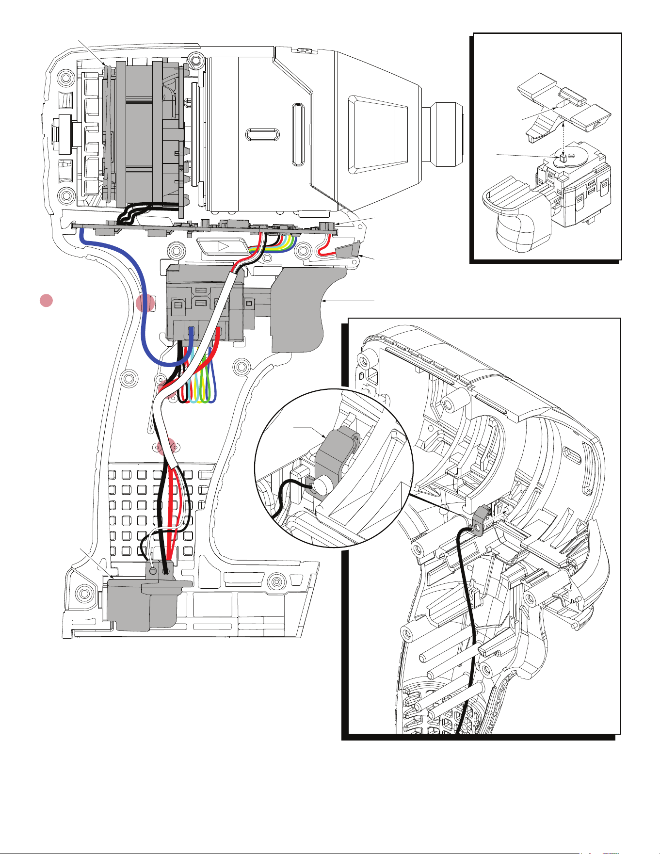
= WIRE TRAPS
or GUIDES
Stator Assembly
PCBA
LED Assembly
On-Off Switch
Battery
Connector
Block Assy.
High
Voltage
Contact
Plate
Install high voltage wire assembly as
shown. Place the contact plate over
post in left housing halve prior to
installing complete electronics
assembly. Route the wire
behind switch and tuck
down in traps.
AS AN AID TO REASSEMBLY, TAKE NOTICE OF WIRE ROUTING AND
POSITION IN WIRE GUIDES AND TRAPS WHILE DISMANTLING TOOL.
BE SURE THAT ALL COMPONENTS OF THE ELECTRONICS KIT
ARE SEATED FIRMLY AND SQUARELY IN THE HANDLE RECESSES.
AVOID PINCHED WIRES, BE SURE THAT ALL WIRES AND SLEEVES
ARE PRESSED COMPLETELY DOWN IN WIRE GUIDES AND TRAPS.
PRIOR TO INSTALLING THE HANDLE COVER ONTO THE HANDLE
SUPPORT, BE SURE THAT THERE ARE NO INTERFERENCES.
Be sure post in shift disc of switch
is inserted into slot of fwd./rev.
shuttle when installing electronics
assembly. Check for proper funct-
ionality prior to screwing
handle halves
together.
Shuttle slot
Shift disc
post