

Fiber Optical Transceiver • Quick Start Guide
I
Legal Information
About this Document
●
This Document includes instructions for using and managing the Product. Pictures, charts, images and all other
information hereinafter are for description and explanation only.
●
The information contained in the Document is subject to change, without notice, due to firmware updates or other
reasons. Please find the latest version of the Document at the Hikvision website (https://www.hikvision.com).
Unless otherwise agreed, Hangzhou Hikvision Digital Technology Co., Ltd. or its affiliates (hereinafter referred to as
"Hikvision") makes no warranties, express or implied.
●
Please use the Document with the guidance and assistance of professionals trained in supporting the Product.
About this Product
This product can only enjoy the after-sales service support in the country or region where the purchase is made.
Acknowledgment of Intellectual Property Rights
●
Hikvision owns the copyrights and/or patents related to the technology embodied in the Products described in this
Document, which may include licenses obtained from third parties.
●
Any part of the Document, including text, pictures, graphics, etc., belongs to Hikvision. No part of this Document
may be excerpted, copied, translated, or modified in whole or in part by any means without written permission.
●
and other Hikvision’s trademarks and logos are the properties of Hikvision in various
jurisdictions.
●
Other trademarks and logos mentioned are the properties of their respective owners.
LEGAL DISCLAIMER
●
TO THE MAXIMUM EXTENT PERMITTED BY APPLICABLE LAW, THIS DOCUMENT AND THE PRODUCT DESCRIBED,
WITH ITS HARDWARE, SOFTWARE AND FIRMWARE, ARE PROVIDED "AS IS" AND "WITH ALL FAULTS AND ERRORS".
HIKVISION MAKES NO WARRANTIES, EXPRESS OR IMPLIED, INCLUDING WITHOUT LIMITATION, MERCHANTABILITY,
SATISFACTORY QUALITY, OR FITNESS FOR A PARTICULAR PURPOSE. THE USE OF THE PRODUCT BY YOU IS AT YOUR
OWN RISK. IN NO EVENT WILL HIKVISION BE LIABLE TO YOU FOR ANY SPECIAL, CONSEQUENTIAL, INCIDENTAL, OR
INDIRECT DAMAGES, INCLUDING, AMONG OTHERS, DAMAGES FOR LOSS OF BUSINESS PROFITS, BUSINESS
INTERRUPTION, OR LOSS OF DATA, CORRUPTION OF SYSTEMS, OR LOSS OF DOCUMENTATION, WHETHER BASED
ON BREACH OF CONTRACT, TORT (INCLUDING NEGLIGENCE), PRODUCT LIABILITY, OR OTHERWISE, IN CONNECTION
WITH THE USE OF THE PRODUCT, EVEN IF HIKVISION HAS BEEN ADVISED OF THE POSSIBILITY OF SUCH DAMAGES
OR LOSS.
●
YOU ACKNOWLEDGE THAT THE NATURE OF THE INTERNET PROVIDES FOR INHERENT SECURITY RISKS, AND
HIKVISION SHALL NOT TAKE ANY RESPONSIBILITIES FOR ABNORMAL OPERATION, PRIVACY LEAKAGE OR OTHER
DAMAGES RESULTING FROM CYBER-ATTACK, HACKER ATTACK, VIRUS INFECTION, OR OTHER INTERNET SECURITY

Fiber Optical Transceiver • Quick Start Guide
II
RISKS; HOWEVER, HIKVISION WILL PROVIDE TIMELY TECHNICAL SUPPORT IF REQUIRED.
●
YOU AGREE TO USE THIS PRODUCT IN COMPLIANCE WITH ALL APPLICABLE LAWS, AND YOU ARE SOLELY
RESPONSIBLE FOR ENSURING THAT YOUR USE CONFORMS TO THE APPLICABLE LAW. ESPECIALLY, YOU ARE
RESPONSIBLE, FOR USING THIS PRODUCT IN A MANNER THAT DOES NOT INFRINGE ON THE RIGHTS OF THIRD
PARTIES, INCLUDING WITHOUT LIMITATION, RIGHTS OF PUBLICITY, INTELLECTUAL PROPERTY RIGHTS, OR DATA
PROTECTION AND OTHER PRIVACY RIGHTS. YOU SHALL NOT USE THIS PRODUCT FOR ANY PROHIBITED END-USES,
INCLUDING THE DEVELOPMENT OR PRODUCTION OF WEAPONS OF MASS DESTRUCTION, THE DEVELOPMENT OR
PRODUCTION OF CHEMICAL OR BIOLOGICAL WEAPONS, ANY ACTIVITIES IN THE CONTEXT RELATED TO ANY
NUCLEAR EXPLOSIVE OR UNSAFE NUCLEAR FUEL-CYCLE, OR IN SUPPORT OF HUMAN RIGHTS ABUSES.
●
IN THE EVENT OF ANY CONFLICTS BETWEEN THIS DOCUMENT AND THE APPLICABLE LAW, THE LATTER PREVAILS.
© Hangzhou Hikvision Digital Technology Co., Ltd. All rights reserved.
Fiber Optical Transceiver • Quick Start Guide
III
Applicable Models
This manual is applicable to the models listed in the following table.
Model
Description
DS-3D01T-A(B)
100 Mbps fiber optical transceiver, 1 × 100 Mbps RJ45 port and 1 × 100 Mbps
SC fiber optical port, transmitter, 20 km
DS-3D01R-A(B)
100 Mbps fiber optical transceiver, 1 × 100 Mbps RJ45 port and 1 × 100 Mbps
SC fiber optical port, receiver, 20 km
Symbol Conventions
The symbols that may be found in this document are defined as follows.
Symbol
Description
Provides additional information to emphasize or supplement important points of
the main text.
Indicates a potentially hazardous situation, which if not avoided, could result in
equipment damage, data loss, performance degradation, or unexpected results.
Indicates a hazard with a high level of risk, which if not avoided, will result in
death or serious injury.

Fiber Optical Transceiver • Quick Start Guide
IV
CONTENTS
Chapter 1 Introduction ............................................................................................................... 1
Product Introduction ............................................................................................................................................ 1
Packing List ........................................................................................................................................................... 1
Appearance ........................................................................................................................................................... 1
Typical Application ................................................................................................................................................ 3
Chapter 2 Installation ................................................................................................................. 4
Lightning Protection, ESD Protection, and Grounding .......................................................................................... 4
Optical Fiber and Optical Component Protection ................................................................................................. 4
Optical Fiber Connection ...................................................................................................................................... 5
Device Installation ................................................................................................................................................ 5
2.4.1 Desktop Placement .................................................................................................................................... 5
2.4.2 Chassis Installation ..................................................................................................................................... 5
Chapter 3 Grounding .................................................................................................................. 8
With Grounding Bar .............................................................................................................................................. 8
Without Grounding Bar ........................................................................................................................................ 8
Chapter 4 Powering On ............................................................................................................. 10
Fiber Optical Transceiver • Quick Start Guide
1
Chapter 1 Introduction
Product Introduction
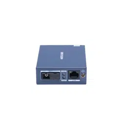
DS-3D01T-A(B) and DS-3D01R-A(B) are 100 Mbps fiber optical transceivers, providing one 100 Mbps
RJ45 port and one 100 Mbps SC fiber optical port. The devices use single-mode optical fibers to
transmit and receive data, achieving high-speed and lossless transmission of data signals over a
maximum of 20 km transmission distance. Featuring compact size, ease of use, wide dynamic range,
and high cost performance, the devices are suitable for hotels, scenic spots, factories, office
buildings, apartments, parking lots, and security systems to set up an efficient network system.
Packing List
Please check if the package is damaged first. If the package is intact, unpack it and check whether
the accessories provided with the product are available by referring to the packing list. Then, you
can continue to install the device.
Packing List
Appearance
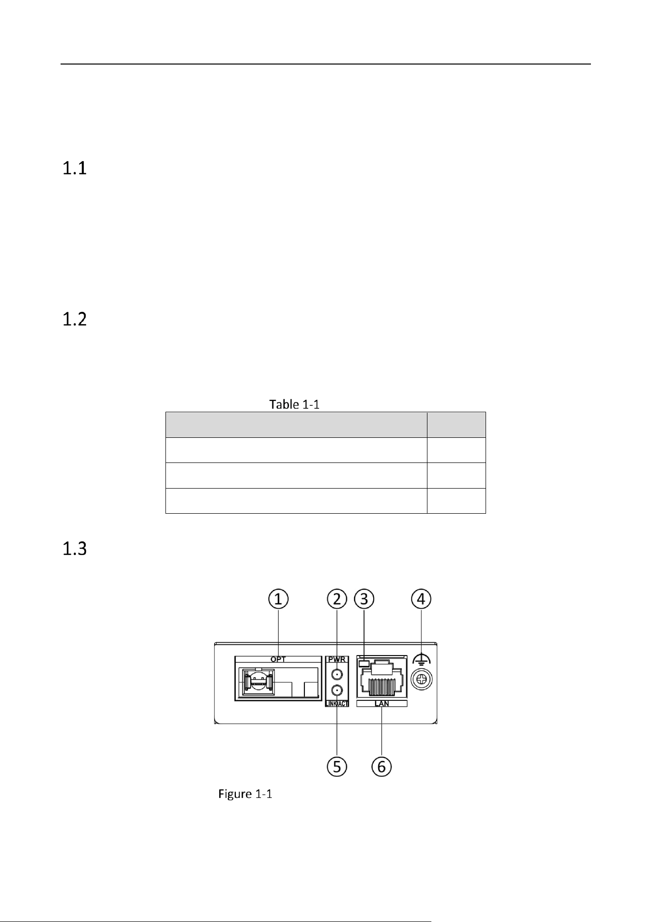
Front Panel
DS-3D01T-A(B)/DS-3D01R-A(B)
Accessory
Quantity
Fiber Optical Transceiver
× 1
Power Adapter
× 1
Regulatory Compliance and Safety Information
× 1
Fiber Optical Transceiver • Quick Start Guide
2
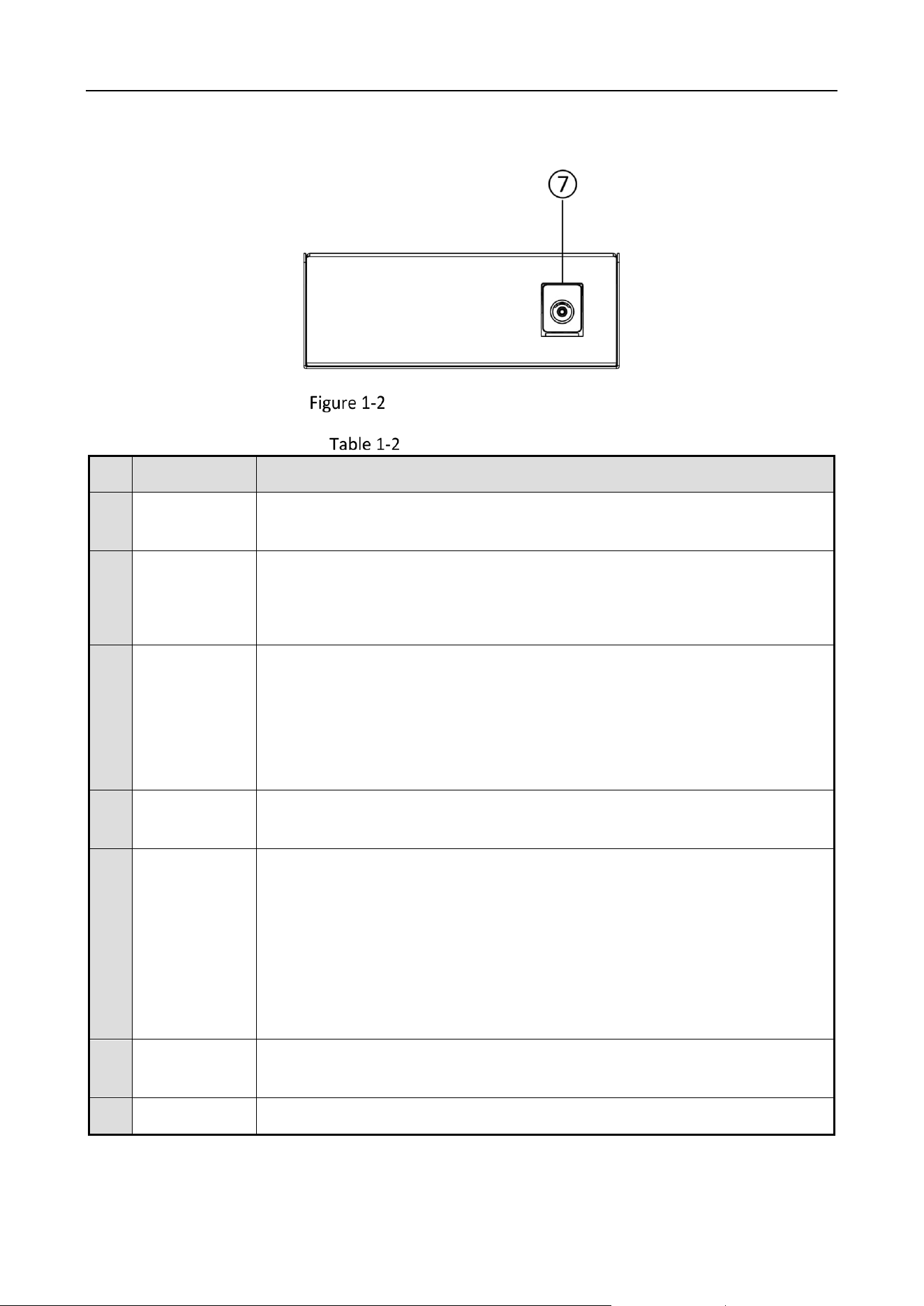
Rear Panel
DS-3D01T-A(B)/DS-3D01R-A(B)
Port/Indicator Description
No.
Port/Indicator
Description
①
OPT
SC fiber optical port, connected to another fiber optical port via a single-
mode optical fiber.
②
PWR
Power indicator.
Solid on: The device is powered on normally.
Unlit: No power supply connected or power supply is abnormal.
③
LINK/ACT
LAN port indicator.
Solid on: The 100 Mbps RJ45 port is connected.
Flashing: The 100 Mbps RJ45 port is transmitting or receiving data.
Unlit: The 100 Mbps RJ45 port is disconnected or connection is
abnormal.
④
Grounding
Terminal
Used for connection to a grounding cable to protect the device from
lightning.
⑤
LINK/ACT
Fiber optical port indicator.
Solid on: The 100 Mbps SC fiber optical port is connected via an optical
fiber.
Flashing: The 100 Mbps SC fiber optical port is transmitting or receiving
data.
Unlit: The 100 Mbps SC fiber optical port is disconnected or connection
is abnormal.
⑥
LAN
100 Mbps RJ45 port, used for connection to another device such as a
network camera (IPC) or switch via a network cable.
⑦
PWR DC 5V
Power jack.
Fiber Optical Transceiver • Quick Start Guide
3
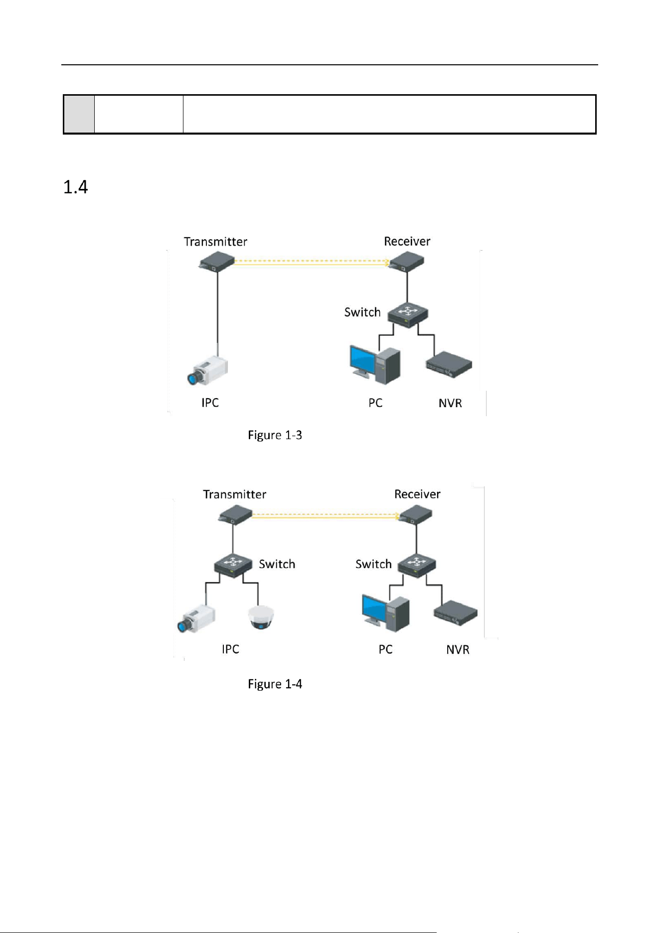
Typical Application
Application 1: IPC Remotely Connected to Fiber Optical Transceiver (Transmitter)
Typical Application 1
Application 2: IPCs Connected to Fiber Optical Transceiver (Transmitter) via a Switch
Typical Application 2
Use the attached power adapter to connect the device’s power jack to a
power socket.

Fiber Optical Transceiver • Quick Start Guide
4
Chapter 2 Installation
This chapter describes how to install the fiber optical transceiver. To avoid device damage and other
harmful consequences, read this chapter carefully.
The device is made of metal shell with anti-rust and anti-corrosion treatment on the surface.
The device shell is not waterproof.
Lightning Protection, ESD Protection, and Grounding
When installing the device, fully consider the impact of lightning strikes at the installation site,
and take grounding and lightning protection measures.
Excessive static electricity may damage optical components and data modules in the device. It
is recommended to power off the fiber optical transceiver when you plug or unplug any cables
to and from the data port(s) on the device.
Use a dedicated grounding cable to connect with the grounding terminal for device grounding.
The copper core insulated wire and cable used in the grounding cable should have a cross-
sectional area of no less than 6 mm², a buried depth of no less than 0.5 m, and a grounding
resistance of less than 4 Ω.
Lightning strikes and static electricity may damage internal components of the device.
Poor grounding can cause interference to video signals and control signals, seriously leading to
inability of front-end devices.
Optical Fiber and Optical Component Protection
The device uses single-mode optical fibers for data transmission. The installation and
transmission specifications of optical fiber links should comply with relevant international or
national standards and requirements.
The optical component(s) of a fiber optical transceiver is/are fragile. When plugging or
unplugging optical fibers, care should be taken to avoid permanent damage to the optical
component(s). Reasonably lay out optical fibers in the equipment room. Do not bend an optical
fiber overly (recommended curvature radius ≥ 50 mm).
The optical fiber connector cannot be contaminated. Please gently wipe it with anhydrous
alcohol before use; otherwise, the transmission effect may be affected. If the optical fiber
Fiber Optical Transceiver • Quick Start Guide
5
connector is not properly connected, large power loss may occur. Therefore, adjust the optical
fiber connector according to the actual situation.
If the fiber optical ports and optical fibers are not in use for a long time, they should be protected
from dust by protective covers.
The light source generated by the optical component(s) of the fiber optical transceiver can cause
permanent damage to human eyes. Do not look directly at the optical component(s) or the fiber
optical ports when the fiber optical transceiver is powered on. To measure the optical power of a
fiber optical transceiver, use a special instrument such as an optical power meter.
Optical Fiber Connection
Check whether the optical fiber links meet the installation requirements described in the
preceding sections.
Use an optical fiber to connect the OPT port on the transmitter to the OPT port on the receiver.
Check whether the LINK/ACT indicator is solid on to determine whether the optical fiber is
properly connected.
Device Installation
Please select an appropriate installation method according to the actual needs. The following figures
are for your reference only.
Ensure that the desktop or chassis is stable and firm enough.
Keep the room well-ventilated. Leave at least 10 cm heat dissipation space around the device.
Place the device on a clean and stable desk.
Keep the device top facing upward when moving or using the device.
The device is hot-swappable when it is used with a fiber optical transceiver chassis.
Fiber Optical Transceiver • Quick Start Guide
6
Please wear anti-static wristbands or gloves and prepare a screwdriver before installation.
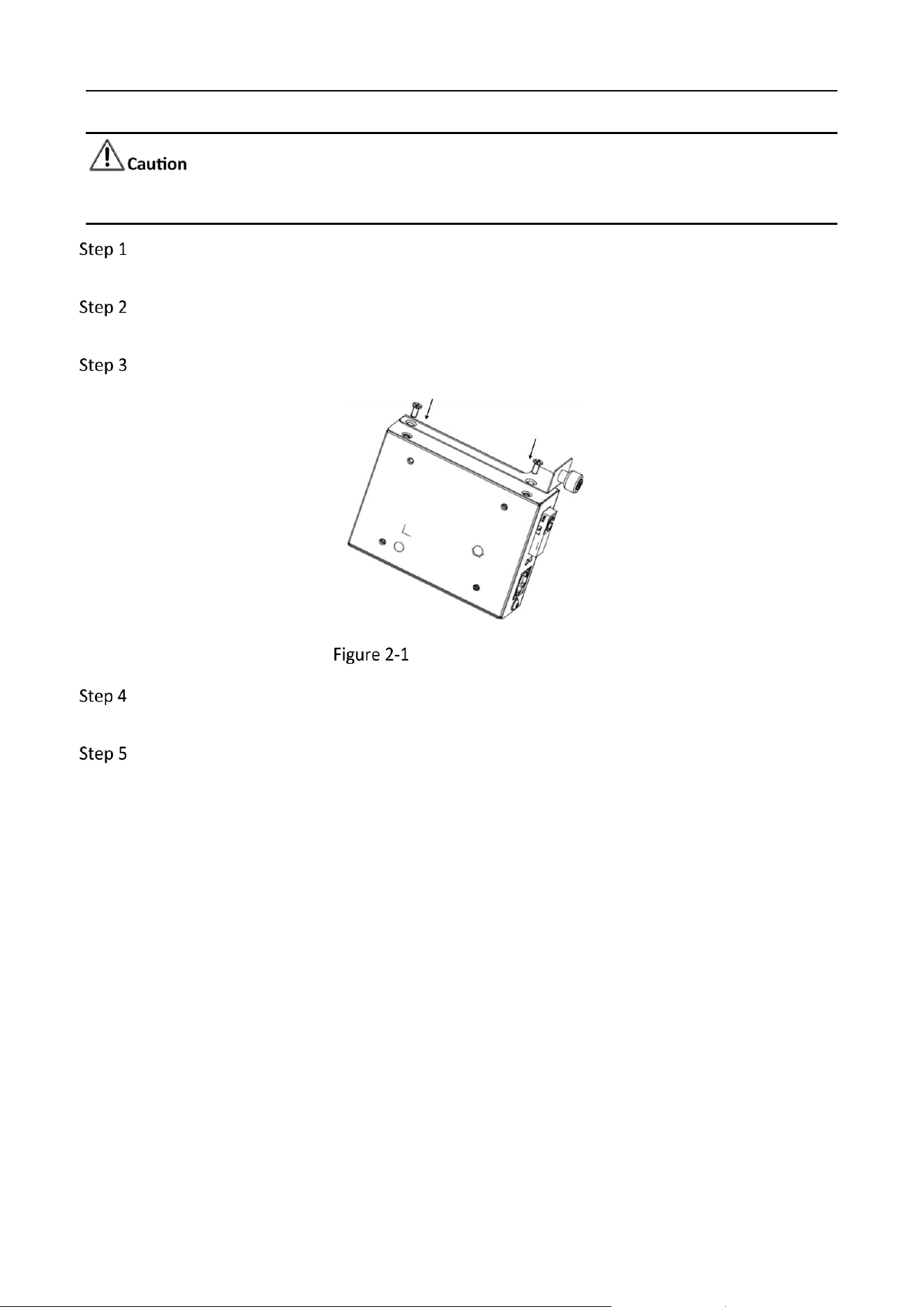
Use a screwdriver to remove the two screws on the side panel (the OPT port side) of the
optical fiber transceiver.
Align the retainer plate (usually provided with the chassis) with the two screw fixing holes on
the device’s side panel.
Tighten the screws to lock the retainer plate onto the device’s side panel.
Install the Retainer Plate
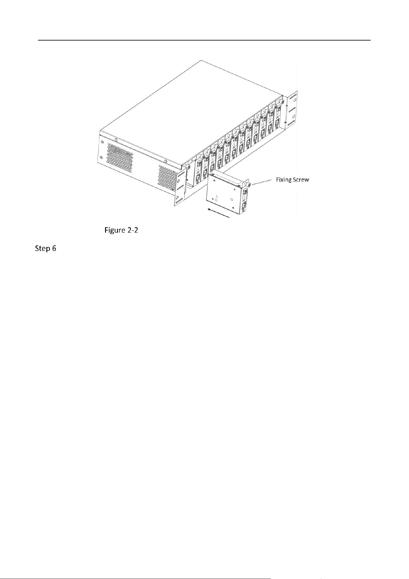
Align the power jack on the device’s rear panel with the DC power socket in an idle slot
inside the chassis.
Slide the fiber optical transceiver into the chassis, as shown in Figure 2-2.
Fiber Optical Transceiver • Quick Start Guide
7
Install the Fiber Optical Transceiver into the Chassis
Tighten the fixing screw on the retainer plate to securely install the device into the chassis.

Fiber Optical Transceiver • Quick Start Guide
8
Chapter 3 Grounding
Grounding is used to quickly release overvoltage and overcurrent induced by lightning on the device,
and to protect personal safety. Select an appropriate grounding method according to the installation
conditions.
The grounding terminal may be located on the front, rear, or side panel of the device. The following
figures are for illustration only.
With Grounding Bar
Connect one end of the grounding cable to the binding post on the grounding bar.
Connect the other end of the grounding cable to the grounding terminal of the device and
tighten the screw.
Grounding with Grounding Bar
Without Grounding Bar
Bury an angle steel or steel pipe (≥ 0.5 m) into the earth.
Weld one end of the grounding cable to the angle steel or steel pipe and embalm the welding
point via electroplating or coating.
Connect the other end of the grounding cable to the grounding terminal.

Fiber Optical Transceiver • Quick Start Guide
9
Grounding with Angle Steel

Fiber Optical Transceiver • Quick Start Guide
10
Chapter 4 Powering On
Please use the attached power adapter to power on the device.
Before powering on your device, make sure that:
The operating power supply is compliant with rated input standard.
Port cables and grounding cables are correctly connected.

0
UD39143B
