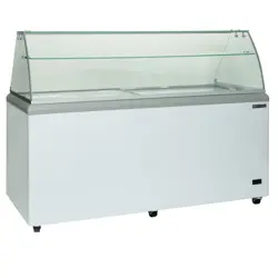
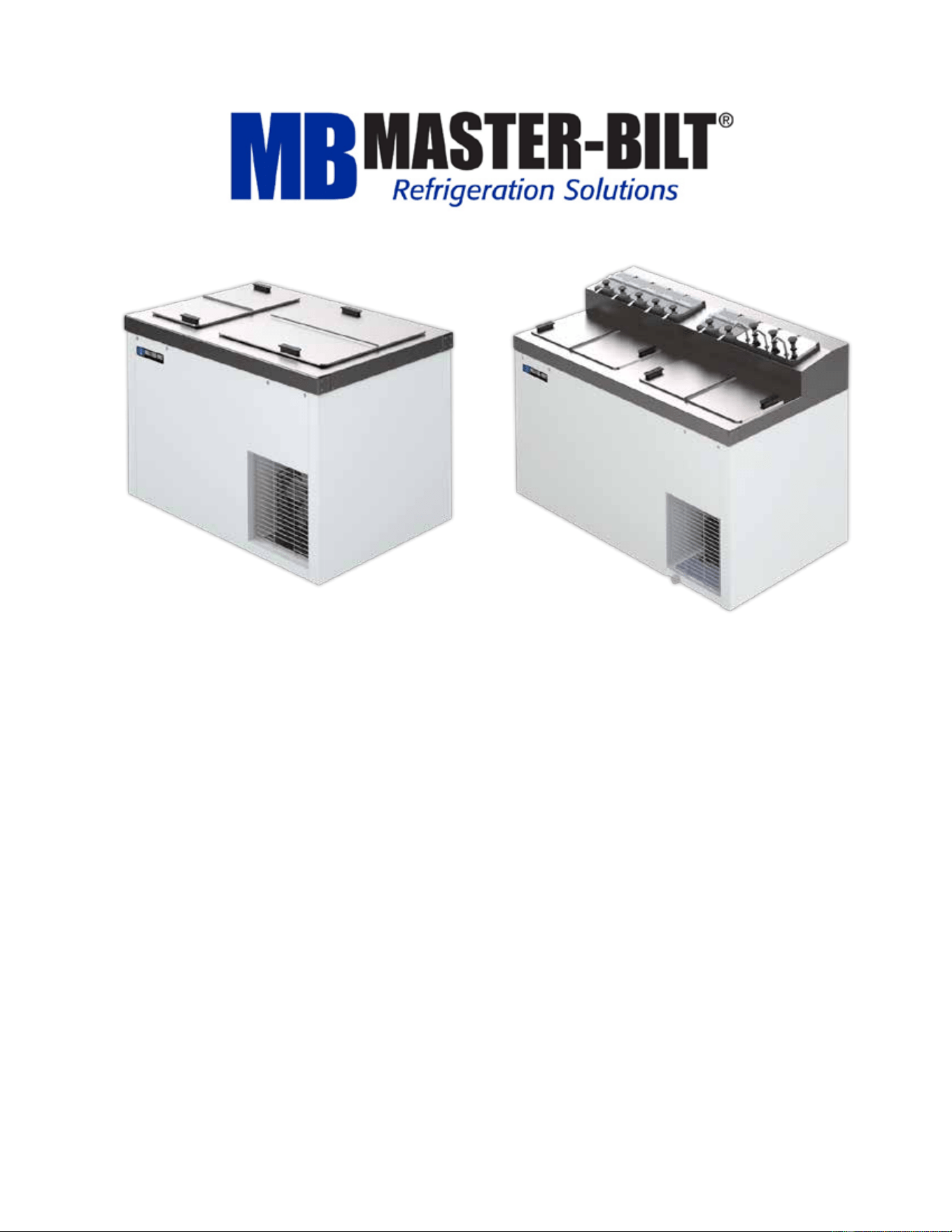
DC and FLR Series
Ice Cream Dipping Cabinets
& Topping Centers
Installation & Operations Manual
Master-Bilt Products
908 Highway 15 North
New Albany, MS 38652
Phone: (800) 684-8988

57-01407 - Rev. E All specifications within this publication subject to change without notice. © 2025 Master-Bilt Products, LLC. All rights reserved.
2
CONTENTS
INTRODUCTION ................................................................................................................................ 3
STORE CONDITIONS ....................................................................................................................... 3
WARNING LABEL AND SAFETY INSTRUCTIONS .......................................................................... 4
INSPECTION FOR SHIPPING DAMAGE .......................................................................................... 5
INSTALLATION INSTRUCTIONS ..................................................................................................... 5
REPLACING CONDENSATE HEATERS .......................................................................................... 7
TEMPERATURE CONTROL ............................................................................................................. 7
CLEANING INSTRUCTIONS ............................................................................................................. 7
TECHNICIAN’S CONSIDERATIONS ................................................................................................. 8
REFRIGERATION EVACUATION AND CHARGING ...................................................................... 10
SERVICE INSTRUCTIONS .............................................................................................................. 11
TROUBLESHOOTING GUIDE ......................................................................................................... 12
PART NUMBERS ............................................................................................................................ 13
DIPPING CABINET OPTIONS ......................................................................................................... 14
DECOMISSIONING, SALE AND DISPOSAL .................................................................................. 15
WIRING DIAGRAM .......................................................................................................................... 16
57-01407 - Rev. E All specifications within this publication subject to change without notice. © 2025 Master-Bilt Products, LLC. All rights reserved.
3
INTRODUCTION
Thank you for purchasing a conventional or flavorail dipping cabinet. This manual contains important instructions for
installing, using and servicing a Conventional Flavorail Dipping Cabinet case. A parts list is included in with this
manual. Read all these documents carefully before installing or servicing your equipment.
CAUTION
This unit uses a flammable refrigerant. Use care when handling and operating to avoid damaging the
refrigerant tubing or increasing the risk of a leak.
All service should be performed by factory authorized personnel. All component parts shall be replaced
with like components to minimize the risk of possible ignition due to incorrect parts or improper service.
This appliance is not intended for use by persons (including children) with reduced physical, sensory
or mental capabilities, or lack of experience and knowledge, unless they have been given supervision
or instruction concerning use of the appliance by a person responsible for their safety.
Children should be supervised to ensure that they do not play with the appliance.
STORE CONDITIONS
The Conventional Flavorail Dipping Cabinet cases are climate class 8 and are designed to operate in the controlled
environment of an air- conditioned store. An appliance’s climate class designates the ideal temperature range within
which it performs best. This classification makes sure that your appliance keeps food fresh whether you live in a hot or
cold climate by assisting you in selecting one that fits your needs. The store temperature should be at or below 75°F
and a relative humidity of 55% or less. At higher temperature or humidity conditions, the performance of these
cases may be affected and the capacity diminished. It is not uncommon in a newly constructed store for the
temperature and humidity to be above design conditions. These excessive conditions may produce sweating in the
case until the store is operational and the ambient environment is more desirable.
The Conventional Flavorail Dipping Cabinet should not be positioned where it is directly exposed to rays of sun or
near a direct source of radiant heat or airflow. This will adversely affect the case and will result in poor performance.
If this case is to be located against a wall there should be at least 4” space between the wall and the back of the
case. This space allows for air circulation behind the case, which prevents condensation on the exterior surfaces.
NOTICE
Read this manual before installing your cabinet. Keep the manual and refer to it before doing any service
on the equipment. Failure to do so could result in personal injury or damage to the cabinet.
DANGER
Improper or faulty hook-up of electrical components of the refrigeration units can result in severe injury or
death. NEVER use an extension cord to power this unit. All electrical wiring hook-ups must be done in
accordance with all applicable local, regional or national standards.
NOTICE
Installation and service of the refrigeration and electrical components of the cabinet must be
performed by a refrigeration mechanic and/or a licensed electrician. If the SUPPLY CORD is damaged,
it must be replaced by the manufacturer, its service agent or similarly qualified persons to avoid a
hazard.
57-01407 - Rev. E All specifications within this publication subject to change without notice. © 2025 Master-Bilt Products, LLC. All rights reserved.
4
The portions of this manual covering refrigeration and electrical components contain technical
instructions intended only for persons qualified to perform refrigeration and electrical work.
This manual cannot cover every installation, use or service situation. If you need additional information, call or write
the customer service department.
Refrigerated Solutions Group
891 County Road U
Hudson, WI 54016
800-388-5253
WARNING LABELS AND SAFETY INSTRUCTIONS
This symbol is used to alert user that there is risk of fire or explosion since flammable refrigerant is
used. This symbol can be observed on back or sides of cabinet.
This symbol is the safety-alert symbol. When you see this symbol on your cabinet or in this manual, be
alert to the potential for personal injury or damage to your equipment.
Be sure you understand all safety messages and always follow recommended precautions and safe operating
practices.
NOTICE TO EMPLOYERS
You must make sure that everyone who installs, uses or services your cabinet is thoroughly familiar with
all safety information and procedures.
Important safety information is presented in this section and throughout this section and throughout the manual.
The following signal words are used in the warnings and safety messages:
DANGER: Severe injury or death will occur if you ignore the message.
WARNING: Severe injury or death can occur if you ignore the message.
CAUTION: Minor injury or damage to your cabinet can occur if you ignore the message.
NOTICE: This is important installation, operation or service information. If you ignore the
message, you may damage your cabinet.
The warning and safety labels shown throughout this manual are placed on your Conventional Flavorail
Dipping Cabinet Products cabinet at the factory. Follow all warning label instructions. If any warning or
safety labels become lost or damaged, call your customer service department.
57-01407 - Rev. E All specifications within this publication subject to change without notice. © 2025 Master-Bilt Products, LLC. All rights reserved.
5
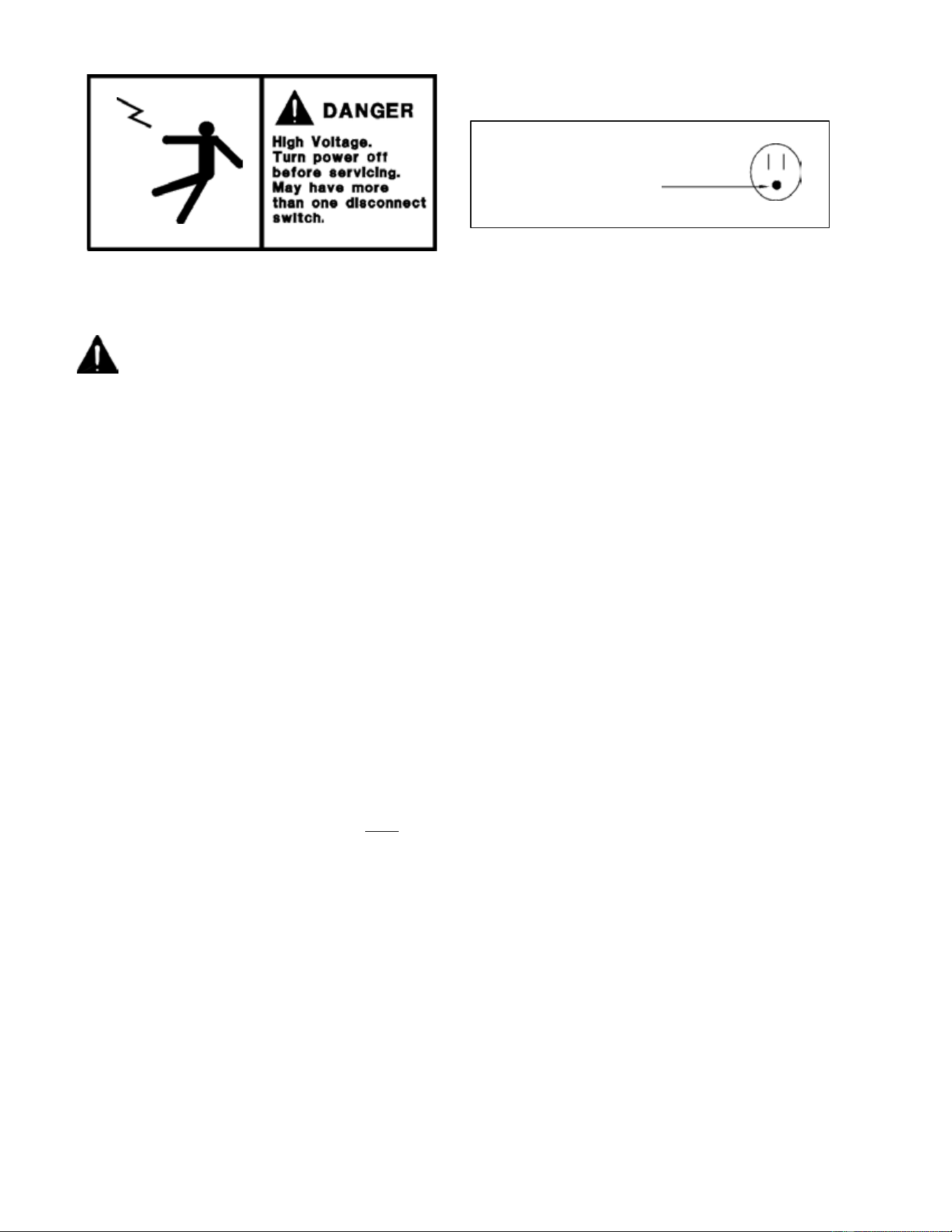
This label is located on top of the electrical control
This label is attached to the cabinet power cord on models with a power cord.
label and on the wiring channel.
NOTICE
• Do not store explosive substances such as aerosol cans with a flammable propellant in this appliance.
• WARNING: Keep clear of obstruction all ventilation openings in the appliance enclosure or in the
structure for building-in.
• WARNING: Do not use mechanical devices or other means to accelerate the defrosting process, other
than those recommended by the manufacturer.
• WARNING: Do not use electrical appliances inside the food/ice storage compartments unless they are
of the type recommended by the manufacturer.
• WARNING: Do not damage the refrigerating circuit.
INSPECTION FOR SHIPPING DAMAGE
You are responsible for filing all freight claims with the delivering truck line. Inspect all cartons and crates for
damage as soon as they arrive. If damage is noted to shipping crates or cartons or if a shortage is found, note this
on the bill of lading (all copies) prior to signing.
If damage is discovered when the cabinet is uncrated, immediately call the delivering truck line and follow up the
call with a written report indicating concealed damage to your shipment. Ask for an immediate inspection of your
concealed damage item. Crating material must be retained to show the inspector from the truck line.
INSTALLATION INSTRUCTIONS
GENERAL INSTRUCTIONS
1. Be sure the equipment is properly installed by competent service people.
2. Keep the equipment clean and sanitary so it will meet your local sanitation codes.
3. Rotate your stock so that older stock does not accumulate. This is especially important for ice cream.
A "first-in-first-out" rotation practice will keep the products in good salable condition.
4. Do not place product in the case when it is soft or partially thawed. Also, product should not be put in the
case for at least 6 hours after it is started.
CAUTION!
GROUND REQUIRED
FOR SAFE OPERATION
57-01407 - Rev. E All specifications within this publication subject to change without notice. © 2025 Master-Bilt Products, LLC. All rights reserved.
6
5. Stock cases as quickly as possible, briefly exposing only small quantities of product to store
temperatures.
6. After removing the power cord from the compressor compartment, be sure both power connections to
thermostat are securely in place.
NOTICE TO STORE OWNERS / MANAGERS
Moisture or liquid around or under the cabinet is a potential slip/fall hazard for persons walking by or
working in the general area of the cabinet. Any cabinet malfunction or housekeeping problem that creates a
slip/fall hazard around or under the cabinet should be corrected immediately.
If moisture or liquid is observed around or under a conventional or flavorail dipping cabinet, an immediate
investigation should be made by qualified personnel to determine the source of the moisture or liquid. The
investigation should determine if the cabinet is malfunctioning or if there is a drainpipe leaking.
ELECTRICAL
WARNING
Before servicing electrical components in the case, make sure all power to case is off. Always use a
qualified technician.
To comply with N.S.F. requirements, this cabinet must be mounted on legs (6” high min.), casters or the base must
be sealed to the floor with NSF listed silicone sealant. Optional casters screw into the holes from which the shipping
bolts were removed.
1. Place cabinet in desired location, leaving approximately 4” behind it to allow condenser discharge air to
escape.
2. Make sure that 115-volt single-phase service is available with sufficient amperage to carry the load of the
cabinet. Electrical codes make it necessary to ship the cabinet with three-prong plugs. However, if it is
necessary to use an adapter for a two-prong outlet, run a grounding wire individually to the cabinet (see
wiring diagram).
3. It is unnecessary to remove the grille from your freezer prior to starting the freezer. All cabinets are
equipped with internal spring mounted compressors. All refrigeration valves are shipped open from the
factory to eliminate the requirement of opening the service valves upon start-up.
4. Each freezer comes with a thermostatic control pre-set for normal operation. When cooler or warmer
temperatures are desired, turn the knob in the appropriate direction (clockwise for colder) as indicated on
the dial plate. Allow the freezer to operate at least four hours prior to readjustment of the control. Also
allow the cabinet to pull down to the desired temperature and cycle off the control at least three times
before product is placed in the freezer.
57-01407 - Rev. E All specifications within this publication subject to change without notice. © 2025 Master-Bilt Products, LLC. All rights reserved.
7
REPLACING CONDENSATE HEATERS
The cabinet features a stainless steel top. Directly below the vinyl collar encasing the openings in the top of your
freezer, there is an anti-sweat heater that prevents condensation during extreme humidity. This heater is easily
replaced by removing the plastic collar without dismantling the top portion of your freezer.
TEMPERATURE CONTROL
WARNING: KEEP HANDS OR ANY MATERIAL OFF THE
FAN BLADE AS FAN MAY COME ON AUTOMATICALLY.
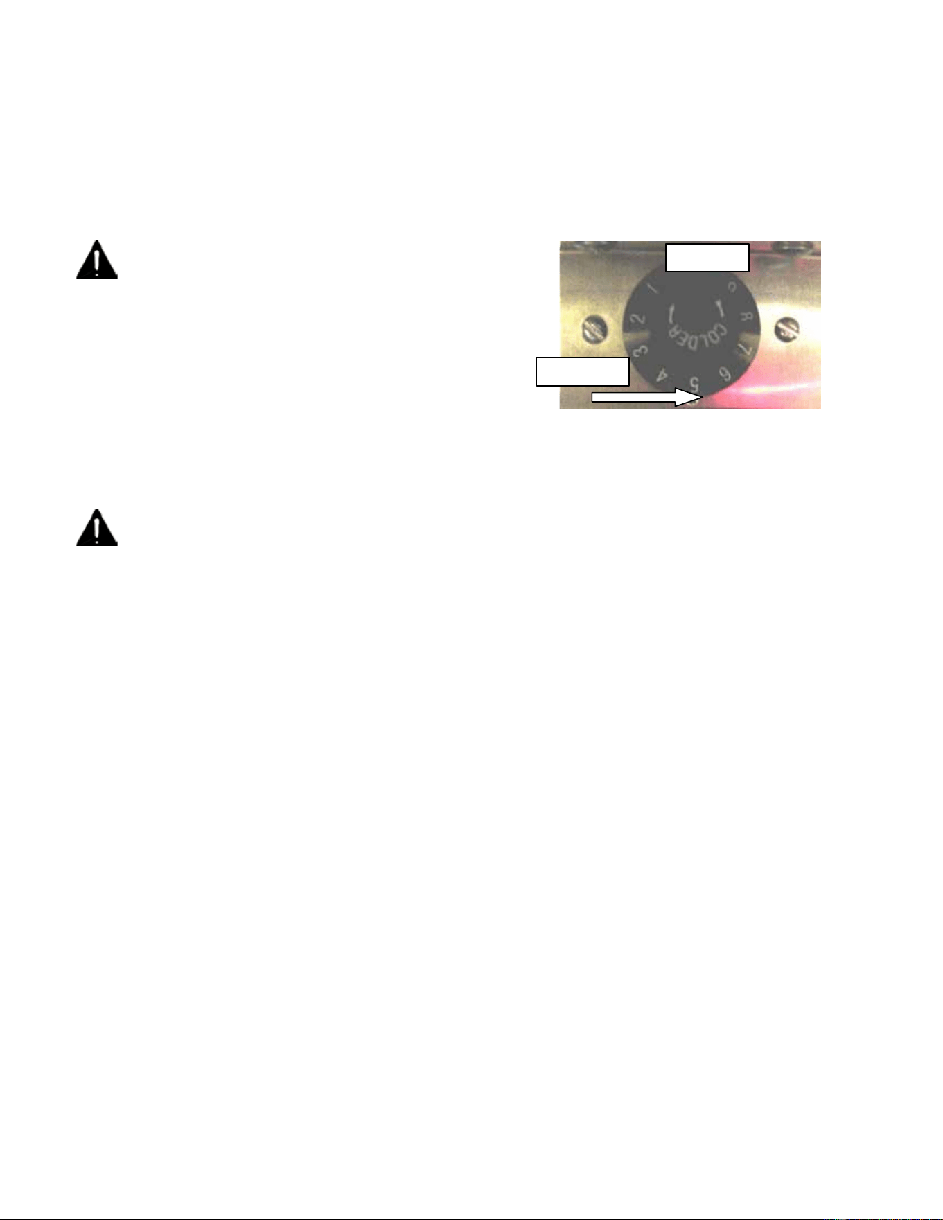
The DC/FLR model cabinet has a temperature control that is
adjustable from #1 (warmest setting) to #9 (coldest setting). Turn the
control knob in line with the punch mark to the desired setting. The
temperature control is located near the condensing unit.
CLEANING INSTRUCTIONS
WARNING: DO NOT REMOVE FROST WITH A KNIFE, PICK, OR SHARP OBJECTS. DO NOT USE
ABRASIVE CLEANERS OR CAUSTIC CLEANERS OR SCOURING PADS
Wipe the cabinet exterior with mild detergent and warm water. Then rinse and wipe dry with a soft cloth. The
cabinet comes with a floor drain to assist in removing excess cleaning solution.
When cleaning the cabinet interior, remove product and place it in a suitable location. Then unplug the power to the
cabinet.
Remove the cap and drain plug, attach a garden hose and route to a floor drain or suitable receptacle while the
cabinet defrosts.
Wash the interior with a mild detergent and warm water solution. Then rinse and dry with a soft cloth. Remove the
garden hose and attach the hose-fitting cap and drain plug.
Plug the cabinet into a wall receptacle and allow the cabinet to reach operating temperature before restocking the
product.
Punch Mark
Dial Plate

57-01407 - Rev. E All specifications within this publication subject to change without notice. © 2025 Master-Bilt Products, LLC. All rights reserved.
8
TECHNICIAN’S CONSIDERATIONS
Technicians should:
• Have an EPA 608 certification type 1 to work on this cabinet.
• Exercise caution when disconnecting quick-connects or opening refrigerant circuits.
• Use ventilation fans anytime a refrigeration circuit is opened.
• Survey the area for ignition sources before opening a refrigeration circuit.
• Correct all nearby electrical faults and discharge all capacitors before opening a refrigeration circuit.
• Avoid working in confined spaces with A3 refrigerants. Ventilation should be used if necessary.
• Check the area for flammable refrigerants with an approved leak detector to find present refrigerant before
starting work. This leak detection equipment should not be arcing or sparking. It should be intrinsically safe.
• Have a fire extinguisher present during service and installation. A dry chemical or CO
2 fire extinguisher should
be adjacent to the charging area.
No person conducting work in relation to a REFRIGERATING SYSTEM which involves exposing any pipe work shall
use any sources of ignition in such a manner that it may lead to the risk of fire or explosion.
All possible ignition sources, including cigarettes, should be kept sufficiently far away from the site of installation,
repairing, removing and disposal, during which refrigerant can possibly be released to the surrounding space.
Prior to work taking place, the area around the equipment shall be surveyed to make sure that there are no flammable
hazards or ignition risks. "No Smoking" signs shall be displayed.
Technicians should ensure that the area is in the open or that it is adequately ventilated before breaking into the
system or conducting any hot work. A degree of ventilation shall continue during the period that the work is
conducted. The ventilation should safely disperse any released refrigerant and preferably expel it externally.
Where electrical components are being charged, they shall be fit for the purpose and to the correct specification. At all
times, the manufacturer's maintenance and service guidelines shall be followed. If in doubt, consult the
manufacturer's technical department for assistance.
FLAMMABLE REFRIGERANT CONSIDERATIONS
The following checks shall be applied to installations using FLAMMABLE REFRIGERANTS:
• The actual REFRIGERANT CHARGE is in accordance with the room size within which the refrigerant-
containing parts are installed.
• The ventilation machinery and outlets are operating adequately and are not obstructed.
• If an indirect refrigerating circuit is being used, the secondary circuit shall be checked for the presence of
refrigerant.
• Marking to the equipment continues to be visible and legible. Markings and signs that are illegible shall be
corrected.
• Refrigerating pipes or components are installed in a position where they are unlikely to be exposed to any
substance which may corrode refrigerant containing purpose and to the correct specification. At all times, the
manufacturer's maintenance and service guidelines shall be followed. If in doubt, consult the manufacturer's
technical department for assistance.

57-01407 - Rev. E All specifications within this publication subject to change without notice. © 2025 Master-Bilt Products, LLC. All rights reserved.
9
CHECKING ELECTRICAL DEVICES
• Repair and maintenance to electrical components shall include initial safety checks and component inspection
procedures.
• If a fault exists that could compromise safety, then no electrical supply shall be connected to the circuit until it is
satisfactorily dealt with.
• If the fault cannot be corrected immediately but it is necessary to continue operation, an adequate temporary
solution shall be used. This shall be reported to the owner of the equipment, so all parties are advised.
INITIAL SAFETY CHECKS
• Ensure the capacitors are discharged. This shall be done in a safe manner to avoid possibility of sparking.
• Ensure no live electrical components and wiring are exposed while charging, recovering or purging the system.
• Ensure there is continuity of earth bonding.
During repairs, technicians should ensure all electrical supplies shall be disconnected from the equipment being
worked upon prior to any removal of sealed covers, etc.
LEAK DETECTION
If it is necessary to have an electrical supply to equipment during service, then a permanently operating form of leak
detection shall be located at the most critical point.
Technicians should ensure cabling will not be subject to wear, corrosion, excessive pressure, vibration, sharp edges,
or any other adverse environmental effects. The effects of aging or continual vibration from sources such as
compressors or fans should also be considered.
Under no circumstances shall potential sources of ignition be used in the searching for or detection of refrigerant
leaks. A halide torch (or any other detector using a naked flame) shall not be used.
The following leak detection methods are deemed acceptable for all refrigerant systems:
• Electronic leak detectors may be used to detect refrigerant leaks but, in the case of FLAMMABLE
REFRIGERANTS, the sensitivity might not be adequate or might need recalibration.
• Detection equipment shall be calibrated in a refrigerant-free area.
• Ensure that the detector is not a potential source of ignition and is suitable for the refrigerant used.
• Leak detection equipment shall be set at a percentage of the LFL of the refrigerant and shall be calibrated to the
refrigerant employed, and the appropriate percentage of gas (25 % maximum) is confirmed.
• Leak detection fluids are also suitable for use with most refrigerants but the use of detergents containing
chlorine shall be avoided as the chlorine can react with the refrigerant and corrode the copper pipework.
Examples of leak detection fluids include bubble method and fluorescent method agents.
If a leak is suspected, all naked flames shall be extinguished. If a leakage of refrigerant is found which requires
brazing, all the refrigerant shall be recovered from the system. Removal of refrigerant shall be according to Clause
101.DVS.9 in UL60335-2-89.

57-01407 - Rev. E All specifications within this publication subject to change without notice. © 2025 Master-Bilt Products, LLC. All rights reserved.
10
REFRIGERANT EVACUATION AND CHARGING
When breaking into the refrigerant circuit to make repairs or any other purpose, use conventional procedures.
However, for flammable refrigerants it is important that best practice be followed, since flammability is a consideration.
Follow this procedure:
• Safely remove refrigerant following local and national regulations
• Purge the circuit with inert gas
• Evacuate (optional for A2L)
• Purge with inert gas (optional for A2L)
• Open the circuit by cutting or brazing
The refrigerant charge shall be recovered into the correct recovery cylinders if venting is not allowed by local and
national codes. For appliances containing flammable refrigerants, the system shall be purged with oxygen-free
nitrogen to render the appliance safe for flammable refrigerants. This process might need to be repeated several
times. Compressed air or oxygen shall not be used for purging refrigerant systems.
For appliances containing flammable refrigerants, refrigerants purging shall be achieved by breaking the vacuum in
the system with oxygen-free nitrogen and continuing to fill until the working pressure is achieved, then venting to
atmosphere, and finally pulling down to a vacuum (optional for A2L). This process shall be repeated until no
refrigerant is within the system (optional for A2L). When the final oxygen-free nitrogen charge is used, the system
shall be vented down to atmospheric pressure to enable work to take place.
Ensure that the outlet for the vacuum pump is not close to any potential ignition sources and that ventilation is
available.
In addition to conventional charging procedures, follow these requirements:
• Ensure that contamination of different refrigerants does not occur when using charging equipment. Hoses or
lines shall be as short as possible to minimize the amount of refrigerant contained in them.
• Cylinders should be kept in an appropriate position according to the instructions.
• Ensure that the REFRIGERATING SYSTEM is earthed prior to charging the system with refrigerant.
• Label the system when charging is complete (if not already).
• Extreme care shall be taken not to overfill the REFRIGERATING SYSTEM.
Prior to recharging the system, pressure test it with the appropriate purging gas. The system shall be leak-tested on
completion of charging but prior to commissioning. A follow up leak test shall be conducted prior to leaving the site.

57-01407 - Rev. E All specifications within this publication subject to change without notice. © 2025 Master-Bilt Products, LLC. All rights reserved.
11
SERVICE INSTRUCTIONS
Prior to beginning work on systems containing FLAMMABLE REFRIGERANTS, safety checks are necessary to ensure
that the risk of ignition is minimized. Work shall be undertaken under a controlled procedure to minimize the risk of a
flammable gas or vapor being present while the work is being performed.
All maintenance staff and others working in the local area shall be instructed on the nature of work being conducted.
Work in confined spaces shall be avoided. The area should be checked with an appropriate refrigerant detector prior to
and during work, to ensure the technician is aware of potentially toxic or flammable atmospheres.
Ensure that the leak detection equipment being used is suitable for use with all applicable refrigerants, i.e., non-
sparking, adequately sealed, or intrinsically safe. Under no circumstances shall potential sources of ignition be used in
the searching for or detection of refrigerant leaks. A halide torch (or any other detector using a naked flame) shall not
be used.
If any hot work is to be conducted on the refrigerating equipment or any associated parts, appropriate fire extinguishing
equipment shall be available. A dry chemical or CO2 fire extinguisher should be adjacent to the charging area.
No person conducting work in relation to a REFRIGERATING SYSTEM which involves exposing any pipe work shall
use any sources of ignition in such a manner that it may lead to the risk of fire or explosion.
All possible ignition sources, including cigarette smoking, should be kept sufficiently far away from the site of
installation, repairing, removing and disposal, during which refrigerant can possibly be released to the surrounding
space.
Prior to work taking place, the area around the equipment shall be surveyed to make sure that there are no flammable
hazards or ignition risks. “No Smoking” signs shall be displayed.
Ensure that the area is in the open or that it is adequately ventilated before breaking into the system or conducting any
hot work. Ventilation shall continue during the period that the work is conducted. The ventilation should safely disperse
any released refrigerant and preferably expel it externally into the atmosphere.
Where electrical components are being changed, they shall be fit for the purpose and to the correct specification. At all
times, the manufacturer’s maintenance and service guidelines shall be followed. If in doubt, consult the manufacturer’s
technical department for assistance.
The following checks shall be applied to installations using FLAMMABLE REFRIGERANTS:
• The actual REFRIGERANT CHARGE is in accordance with the room size within which the refrigerant
containing parts are installed
• The ventilation machinery and outlets are operating adequately and are not obstructed
• If an indirect refrigerating circuit is being used, the secondary circuit shall be checked for the presence of
refrigerant
• Marking to the equipment continues to be visible and legible. Markings and signs that are illegible shall be
corrected
• Refrigerating pipe or components are installed in a position where they are unlikely to be exposed to any
substance which may corrode refrigerant containing parts
Repair and maintenance to electrical components shall include initial safety checks and component inspection
procedures. If a fault exists that could compromise safety, then no electrical supply shall be connected to the circuit
until it is satisfactorily dealt with.
If the fault cannot be corrected immediately but it is necessary to continue operation, an adequate temporary solution
shall be used. This shall be reported to the owner of the equipment, so all parties are advised.

57-01407 - Rev. E All specifications within this publication subject to change without notice. © 2025 Master-Bilt Products, LLC. All rights reserved.
12
Initial safety checks shall include:
• That capacitors are discharged: this shall be done in a safe manner to avoid possibility of sparking
• That no live electrical components and wiring are exposed while charging, recovering or purging the system
• That there is continuity of earth bonding.
TROUBLESHOOTING GUIDE
1. High head pressure and high back pressure:
A. Condenser coil clogged or restricted.
B. Condenser fan motor defective.
C. Air in the system.
D. Refrigeration overcharge.
2. Low back pressure and low head pressure:
A. Capillary tube restriction.
B. Refrigerant undercharged.
C. Leak in system.
3. Pressures normal – cabinet warm:
A. Refrigerant undercharged.
B. Control set too warm.
4. Compressor starts and runs – but cycles on overload:
A. Low voltage.
B. Overload protector defective.
C. High head pressure (see #1).
5. Compressor will not start – hums, but cycles on overload:
A. Low voltage.
B. Relay defective.
C. Overload defective.
D. High head pressure (see #1).
6. Cabinet sweating:
A. High ambient humidity.
B. Defective condensate heater.
7. Special service situations:
If moisture or liquid is observed around or under the cabinet, qualified personnel should investigate
immediately to determine its source. The investigation should determine if the cabinet is malfunctioning or
if there is a simple housekeeping problem.
Moisture or liquid around or under a cabinet is a potential slip/fall hazard for people walking by or working
in the general area of the cabinet.
Any cabinet malfunction or housekeeping problem that creates a slip/fall hazard around or under a cabinet
should be corrected immediately.
57-01407 - Rev. E All specifications within this publication subject to change without notice. © 2025 Master-Bilt Products, LLC. All rights reserved.
13
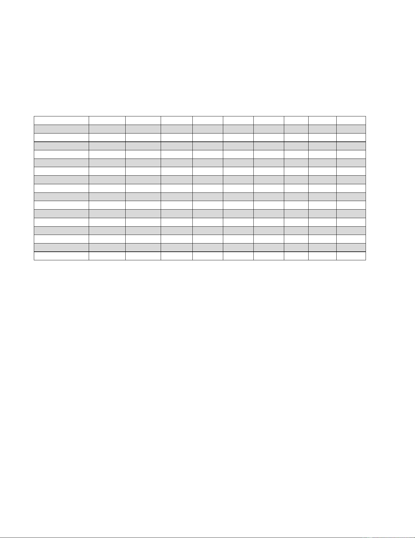
PART NUMBERS
CAUTION:
Use only cabinet manufacturer OEM parts for the R290 product to minimize the risk of ignition
due to incorrect parts.
Failure to observe this caution could cause damage to cabinet, explosion, fire, injury, or even death.
Use this chart when ordering replacement parts and be ready to provide your cabinet serial number.
Description
DC-2S
DC-4D
DC-4S
DC-6D
DC-8D
DC-10D
DC-12D
FLR-60
FLR-80
Capillary Tube
11-02012
11-02013
11-02012
11-02012
11-02014
11-02021
11-02016
11-02012
11-02014
Compressor
03-51004
03-51005
03-51005
03-51005
03-51006
03-51007
03-51007
03-51005
03-51006
Condenser coil
07-01180
07-01180
07-01180
07-01180
07-01180
07-14194
07-14194
07-01180
07-01180
Condenser Fan Blade
15-13092
15-13092
15-13092
15-13092
15-13092
15-13092
15-13092
15-13092
15-13092
Condenser Fan Motor
13-13279
13-13279
13-13279
13-13279
13-13279
13-13279
13-13279
13-13279
13-13279
Divider
25-00105
25-00103
25-00105
25-00103
25-00103
25-00103
25-00103
25-00103
25-00103
Drier
09-10644
09-10644
09-10644
09-10644
09-10644
09-10644
09-10644
09-10644
09-10644
Grille
25-00104
25-00104
25-00104
25-00104
25-00104
25-00104
25-00104
25-00104
25-00104
Heater
17-09297
17-09293
17-09298
17-09294
17-09299
17-09295
17-09296
17-09298
17-09298
Lid, Double
N/A
44-00471
N/A
44-00471
44-00471
44-00471
44-00471
N/A
N/A
Lid, Single
44-00470
N/A
44-00470
44-00470
N/A
44-00470
N/A
44-00470
44-00470
Power Cord
21-01201
21-01201
21-01201
21-01201
21-01201
21-01201
21-01201
21-01201
21-01201
Temperature Control
19-14239
19-14239
19-14239
19-14239
19-14239
19-14239
19-14239
19-14239
19-114239
Vinyl Collar,63-1/4”
37-00518
N/A
37-00518
37-00518
N/A
37-00518
N/A
37-00518
37-00518
Vinyl Collar,85-1/4”
N/A
37-00516
N/A
37-00516
37-00516
37-00516
37-00516
N/A
N/A
Leg Leveler
27-00592
27-00592
27-00592
27-00592
27-00592
27-00592
27-00592
27-00592
27-00592
57-01407 - Rev. E All specifications within this publication subject to change without notice. © 2025 Master-Bilt Products, LLC. All rights reserved.
14
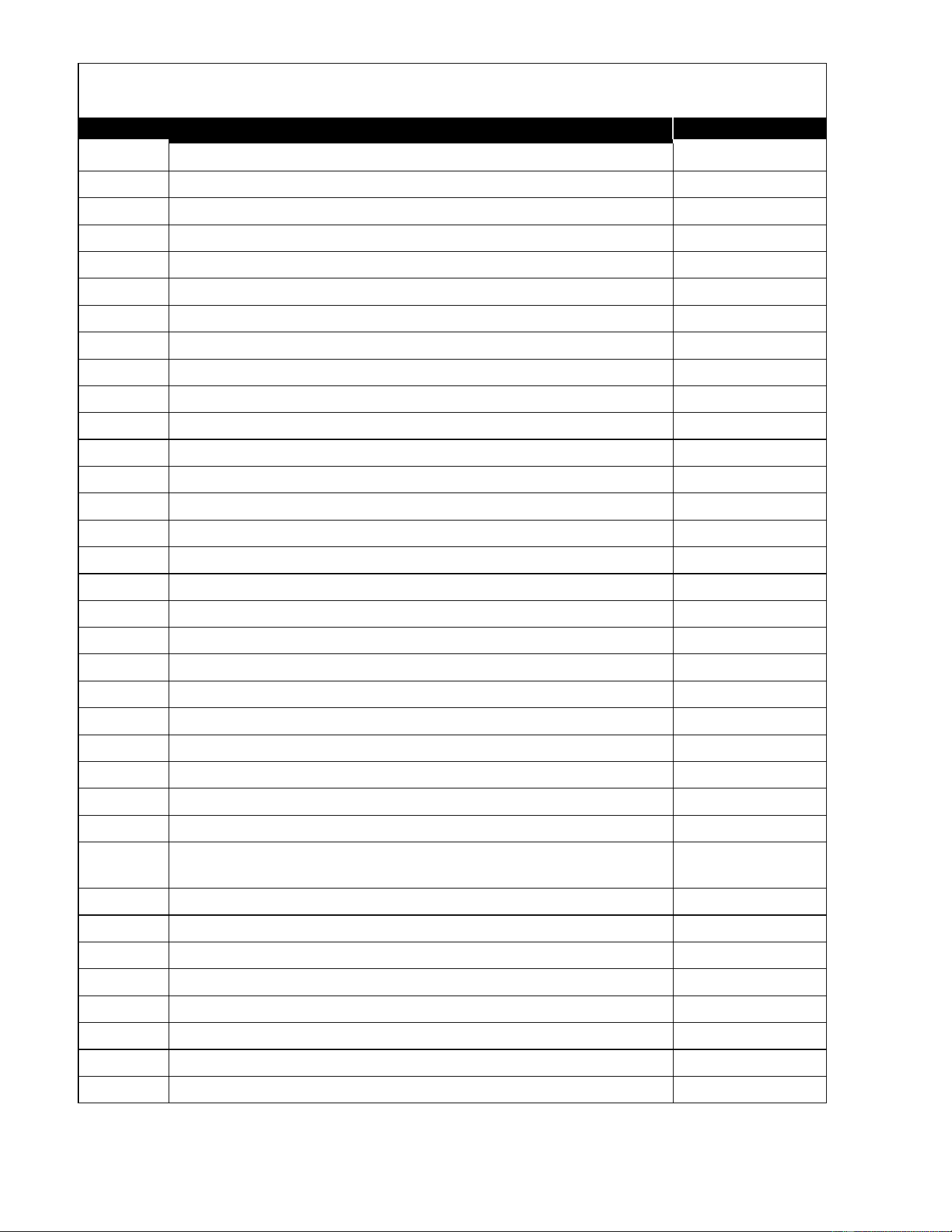
Dipping Cabinet Options
PART NO.
DESCRIPTION
SHIP WT.
CASTERS
A039-11140
Set of 4, 2" diameter casters for DC-2S, DC-4S, DC-4D, DC-6D, DC-8D, FLR-60, FLR-80
4/2
A044-11140 Set of 6, 2" diameter for DC-10D and DC-12D 5/2
LEG KITS
A039-11170 6" leg kit for DC-2S, DC-4S, DC-4D, DC-6D, DC-8D, FLR-60, FLR-80 18/8
A044-11170 6" leg kit for DC-10D and DC-12D 26/12
LID LOCKING KITS - LESS LOCKS
A041-11129 For DC-2S and DC-4D 3/1
A051-11229 For DC-4S 5/2
A043-11129 For DC-6D and DC-8D 5/2
A044-11129
For DC-10D and DC-12D
6/3
A050-11229 For FLR-60 5/2
A051-11229 For FLR-80 5/2
LIDS
44-00470 Single lid for DC models 5/2
44-00471
Double lid for DC models
9/4
LOAD LEVEL SHELVES
A039-18127 Load level shelf for DC-2S *
A040-18127 Load level shelf for DC-4S *
A041-18127 Load level shelf for DC-4D
16/7
A042-18127 Load level shelf for DC-6D
20/9
A043-18127 Load level shelf for DC-8D
22/10
A044-18127 Load level shelf for DC-10D
24/11
A045-18127 Load level shelf for DC-12D *
DIPPER WELL
A060-20400 With installation kit for all DC and FLR models 4/2
PUMP & JAR ASSEMBLIES FOR FLR MODELS (STANDARD FLR CABINETS DO
NOT INCLUDE OPTIONAL PUMPS AND JARS)
A050-11151 For FLR-60: 2 chocolate/syrup pumps, 3 jars with lids and spoons 12/5
A051-11151 For FLR-80: 3 chocolate/syrup pumps, 7 jars with lids, 6 spoons 20/9
INDIVIDUAL PARTS FOR FLR MODELS
44-01117 Chocolate pump 3/1
44-01119 Fruit jar (does not include hinged lid or ladle) 3/1
44-01118 Syrup jar (does not include hinged lid or ladle) 3/1
44-01121 Hinged lid (for individual fruit jar) 1/0.4
44-01120 Ladle 1/0.4
* Contact factory

57-01407 - Rev. E All specifications within this publication subject to change without notice. © 2025 Master-Bilt Products, LLC. All rights reserved.
15
DECOMMISSIONING, SALE AND DISPOSAL
If you sell or give away your dipping cabinet, you must make sure that all safety labels and the installation and
service manual are included with it. If you need replacement labels or manuals, contact the customer service
department.
The customer service department should be contacted at the time of sale or disposal of your cabinet so records
may be kept of its new location.
If you sell or give away your cabinet and you evacuate the refrigerant charge before shipment, the refrigerant
charge must be properly recovered in compliance with section 608 of the Clean Air Act, effective November 1995,
and in accordance with all applicable local, regional, or national standards.
Before conducting this procedure, make sure the technician is familiar with the equipment. Prior to the task being
conducted, an oil and refrigerant sample must be taken in case analysis is required prior to re-use of recovered
refrigerant. It is essential that electrical power is available before starting the task.
• Isolate the system electrically.
• Before attempting the procedure, ensure that:
o Mechanical handling equipment is available, if required, for handling refrigerant cylinders
o All personal protective equipment is available and being used correctly
o The recovery process is supervised at all times by a competent person
o Recovery equipment and cylinders conform to the appropriate standards
• Pump down refrigerant system, if possible.
• If a vacuum is not possible, make a manifold so that refrigerant can be removed from various parts of the system.
• Make sure that cylinder is situated on the scales before recovery takes place.
• Start the recovery machine and operate in accordance with instructions.
• Do not overfill cylinders (no more than 80% volume liquid charge).
• Do not exceed the maximum working pressure of the cylinder, even temporarily.
• When the cylinders have been filled correctly and the process completed, make sure that the cylinders and the
equipment are removed from site promptly and all isolation valves on the equipment are closed off.
• Recovered refrigerant shall not be charged into another REFRIGERATING SYSTEM unless it has been cleaned
and checked.
Equipment shall be labeled stating that it has been de-commissioned and emptied of refrigerant. The label shall be
dated and signed. For appliances containing FLAMMABLE REFRIGERANTS, ensure that there are labels on the
equipment stating the equipment contains FLAMMABLE REFRIGERANT.
57-01407 - Rev. E All specifications within this publication subject to change without notice. © 2025 Master-Bilt Products, LLC. All rights reserved.
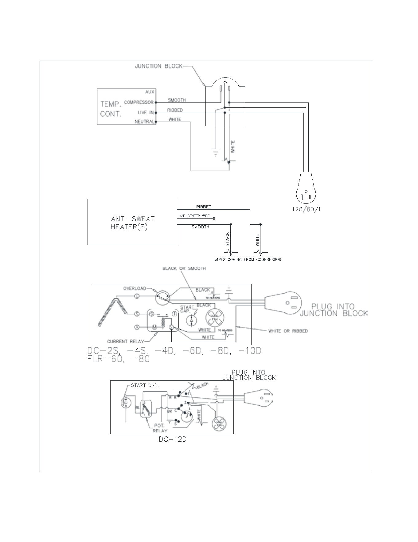
16
WIRING DIAGRAM