Headless
Screw (D)
Lock Nut (E)
WARNING:
TO AVOID RISK OF ELECTRICAL SHOCK, BE SURE TO SHUT OFF
POWER BEFORE INSTALLING OR SERVICING THIS FIXTURE.
NOTES: 1. Before installing, consult local electrical codes for wiring and grounding requirements.
2. Read and save these instructions.
Page 1 / 2
240703
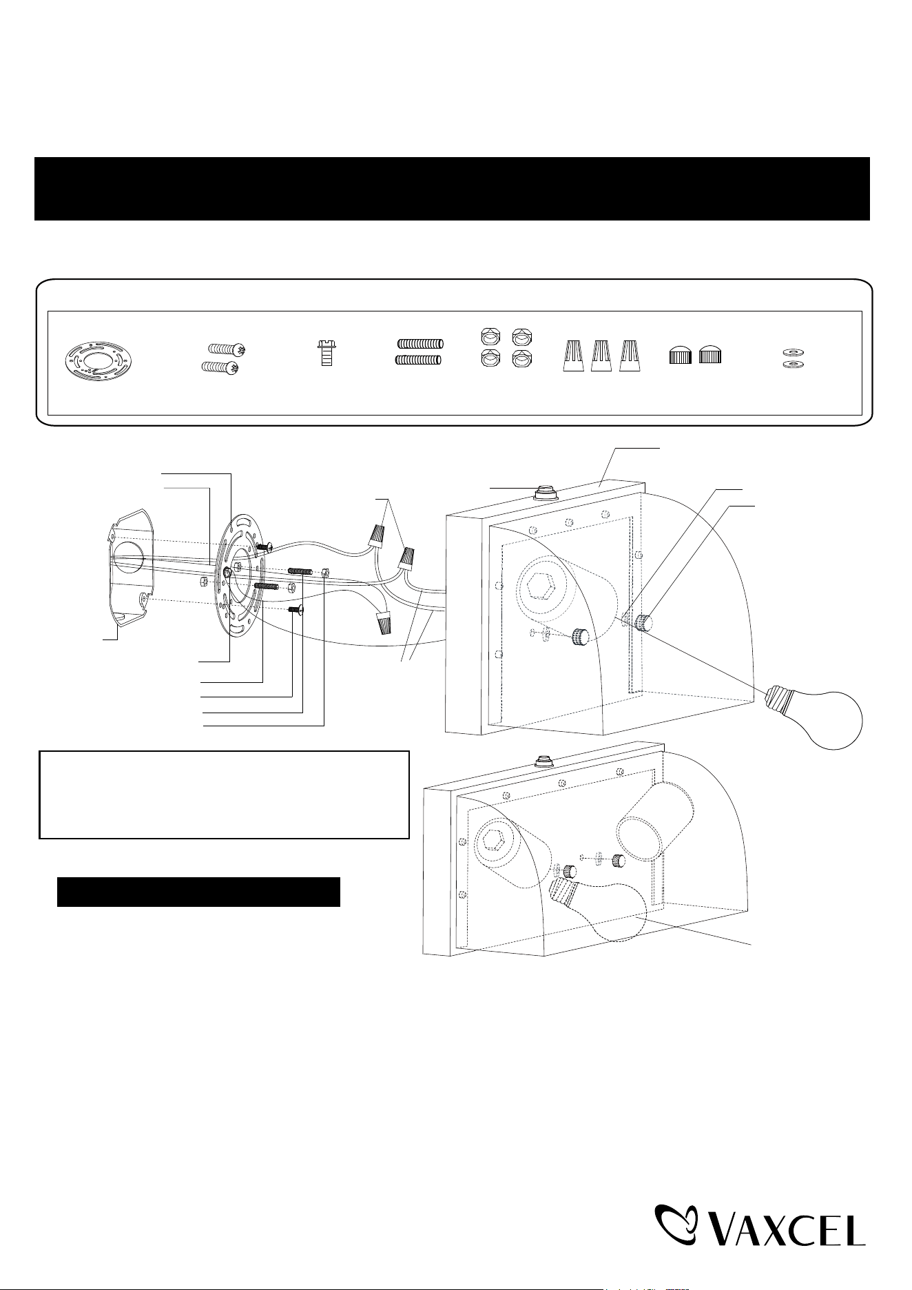
1.
Thread two headless screws through the mounting
plate, and then secure them with four lock nuts
(two on each side of the mounting plate). Adjust the
length of the headless screws if necessary.
Note: Make sure that the headless screws are lined up horizontally to make the fixture level.
2. Attach the mounting plate to the outlet box by using two mounting screws.
3. Pull out the source wires from the outlet box. Make wire connections using wire nuts as follows:
---Connect the hot wire (usually black insulation) from the fixture to the black wire from the power source.
---Connect the neutral wire (usually white insulation) from the fixture to the white wire from the power source.
---Attach the fixture grounding wire (usually green insulation or bare wire) to the mounting plate with the green
grounding screw, and then connect it to the house grounding wire with the wire nut.
Carefully put the wires back into the outlet box.
4. Attach the fixture to the mounting plate by inserting headless screws into holes on back plate, and then secure it
with two rubber pads and two ball nuts.
NOTE:With silicone caulking compound, caulk completely around where the back plate meets with the
wall surface to prevent water from seeping into the outlet box.
House Grounding Wire
Green Grounding Screw (C)
Wire Nut (F)
Mounting Screw (B)
Headless Screw (D)
Outlet Box
Fixture Wire
Lock Nut (E)
Mounting Plate (A)
Fixture Grounding Wire
Mounting Plate (A)
Rubber Pad (H)
T0199
T0200
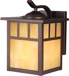
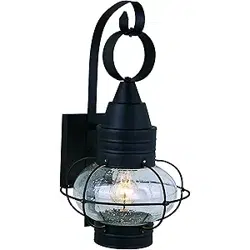
ASSEMBLY AND INSTALLATION
INSTRUCTIONS
T0199 / T0200
Mounting Screw (B)
Wire Nut (F)
Ball Nut (G)
Bulb Type A Max.100W
(not included)
Bulb Type A Max.2-40W
(not included)
Rubber Pad(H)
Ball Nut(G)
Fixture
Photocell
Hardware Package (included):
Green Grounding
Screw (C)
Turn off the power at fuse or circuit box.
Installation Steps
IMPORTANT:
The sensor has an excellent photocell function
to enable the light to turn on at dusk and off at
dawn automatically.
Headless
Screw (D)
Lock Nut (E)
1 Year Warranty
How can warranty service be obtained?
1-800-482-9235
Vaxcel warrants all of our products against defects in workmanship and finishes for one year following the date of
shipment.
Exclusions: This warranty does not include the failure of products from extreme acts of nature; environmental conditions
not suited for the products intended use; operation in temperatures outside of the range specified in the instruction
manual; usage with improper power supply, power surges or dips. For coastal locations, some corrosion is considered
normal for the environment.
Vaxcel reserves the right to repair, replace or issue a credit for any properly installed product, provided it is returned per
RMA instruction. This warranty is limited to the cost of the product only and does not extend to transportation, installation
or replacement costs.
Page 2 / 2
240703
Mounting Plate (A)
Rubber Pad (G)
5. Install a bulb (bulbs) (not included). Check relamping label at socket area or packaging for maximum allowed wattage.
Turn on the power at fuse or circuit box.
The following parts are available for re-order if damaged or missing.
Spare Parts List:
Assembly Kit
5417MM (1 SET)
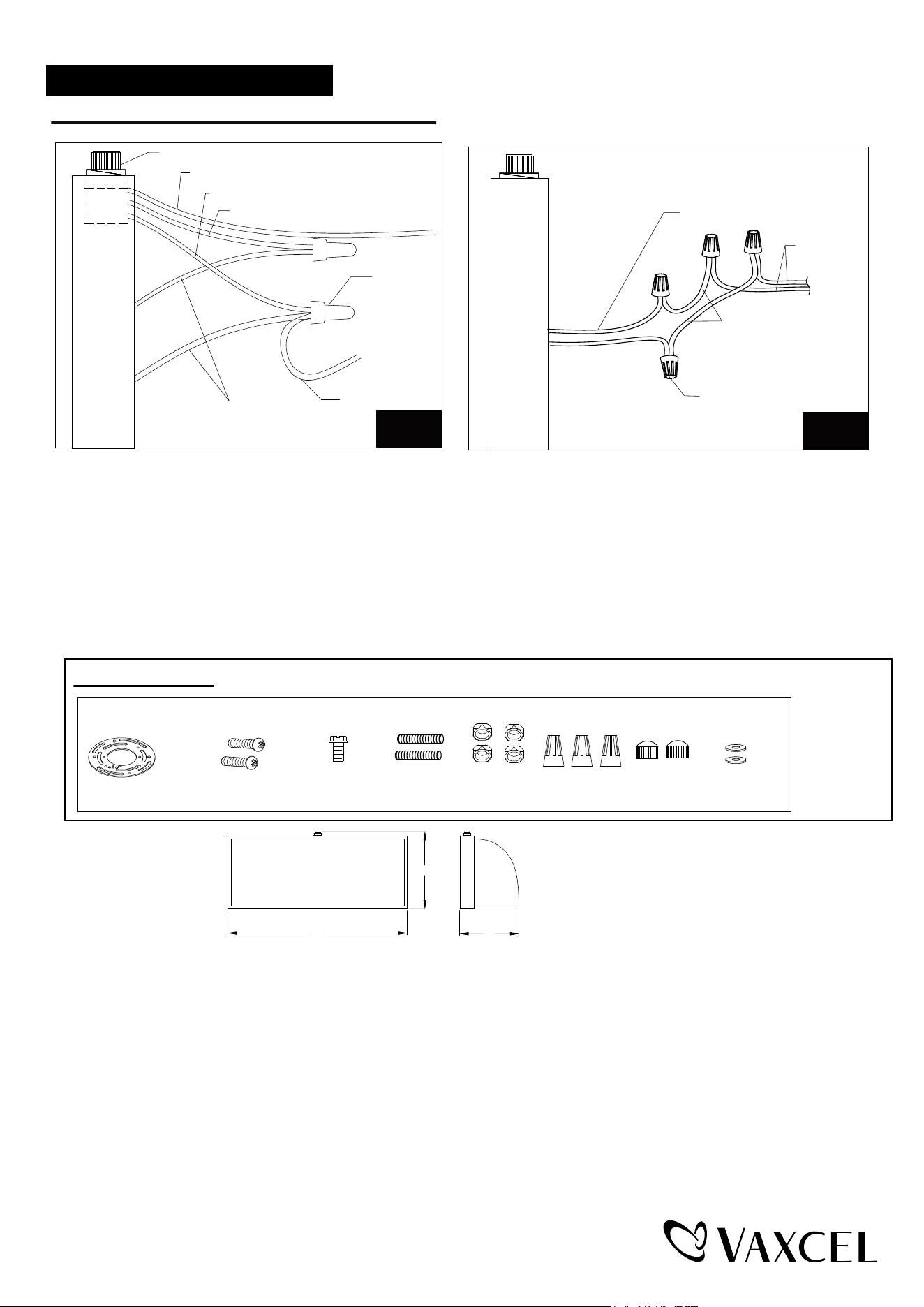
1. Turn off the power at the fuse or circuit box before starting installation.
2. Loosen the wire nuts connected with the wires from photocell. (See Fig.1)
Note: Do not move the photocell to prevent water from seeping into the outlet box.
3. Take a white pigtail and black pigtail and make wire connections using wire nuts: (See Fig.2)
a. The black wire from the fixture to one end of the black pigtail.
b. The white wire from the fixture to one end of the white pigtail.
c. The other end of the black pigtail to the black wire from the power source.
d. The other end of the white pigtail to the white wire from the power source.
Put all wires back into the back plate of the fixture.
Photocell
White Wires From Photocell
Wire Nuts
Wires From Fixture
Wires From Fixture
Wires From
Main Power
Wire Nut
White Pigtail
Pigtail
Red Wires From Photocell
Black Wires From Photocell
Operation the Unit Without Photocell
Fig.
1
Fig
.2
Mounting Screw (B)
Wire Nut (F)
Ball Nut (G)
Green Grounding
Screw (C)
A
B
C
T0199
A: 7"
B: 4-7/8"
C: 4"
T0200
A: 12"
B: 4-7/8"
C: 4"