
30121800 • 4/22
Printed in USA
Operator’s Manual
Manuel du Utilisateur
Professional Series
With Hydrostatic Drive
ENGLISH
FRANÇAIS
E10
Models
926081 – Pro 36 EFI
(SN 000101 +)
926091 – Pro 28 EFI RapidTrak
(SN 000101 +)
Sno-Thro
®

WELCOME . . . . . . . . . . . . . . . . . . . . . . 1
Register Your Product!. . . . . . . . . . . . . . 1
SAFETY. . . . . . . . . . . . . . . . . . . . . . . . . 2
Practices & Laws . . . . . . . . . . . . . . . . . . 2
Emission Control System. . . . . . . . . . . . 2
Required Operator Training . . . . . . . . . . 2
Safety Alert Symbol . . . . . . . . . . . . . . . . 2
Signal Words . . . . . . . . . . . . . . . . . . . . . 2
Safety Decals. . . . . . . . . . . . . . . . . . . . . 3
Safety Rules. . . . . . . . . . . . . . . . . . . . . . 4
CONTROLS & FEATURES. . . . . . . . . . 8
Engine Key. . . . . . . . . . . . . . . . . . . . . . . 10
Electric Start Button . . . . . . . . . . . . . . . . 10
Throttle Control Knob. . . . . . . . . . . . . . . 10
Speed Selector Lever . . . . . . . . . . . . . . 10
Attachment
Clutch Lever (Right Side) . . . . . . . . . . . 10
Traction Drive
Clutch Lever (Left Side) . . . . . . . . . . . . 11
Dual Handle Interlock. . . . . . . . . . . . . . . 11
Height Adjustment Lever (Right Side) . . 11
Discharge Chute Rotation Lever . . . . . . 11
Discharge Chute Deflector Lever. . . . . . 12
Discharge chute control Switch . . . . . . . 12
Heated Hand Grip Switch . . . . . . . . . . . 12
Scraper Blade . . . . . . . . . . . . . . . . . . . . 12
Drift Cutter . . . . . . . . . . . . . . . . . . . . . . . 12
Skid Shoe. . . . . . . . . . . . . . . . . . . . . . . . 12
Auger . . . . . . . . . . . . . . . . . . . . . . . . . . . 12
Impeller . . . . . . . . . . . . . . . . . . . . . . . . . 12
Shear Bolt . . . . . . . . . . . . . . . . . . . . . . . 13
Auto-Turn™ Steering . . . . . . . . . . . . . . . 13
OPERATION . . . . . . . . . . . . . . . . . . . . . 13
Emergency Stopping . . . . . . . . . . . . . . . 13
Before Operating Unit . . . . . . . . . . . . . . 13
Start The Engine . . . . . . . . . . . . . . . . . . 13
Operate Unit. . . . . . . . . . . . . . . . . . . . . . 14
Stop the Engine . . . . . . . . . . . . . . . . . . . 15
Move Unit Manually . . . . . . . . . . . . . . . . 15
Transport Unit . . . . . . . . . . . . . . . . . . . . 15
Engine Operation Angle. . . . . . . . . . . . . 16
MAINTENANCE . . . . . . . . . . . . . . . . . . 16
Service Position. . . . . . . . . . . . . . . . . . . 16
Maintenance Schedule . . . . . . . . . . . . . 16
Service Parts . . . . . . . . . . . . . . . . . . . . . 16
Add Fuel Stabilizer. . . . . . . . . . . . . . . . . 17
Check Dual Handle Interlock . . . . . . . . . 17
Check Fasteners . . . . . . . . . . . . . . . . . . 17
Check Clutch Operation. . . . . . . . . . . . . 17
Check Tire Pressure . . . . . . . . . . . . . . . 17
Check Engine Oil . . . . . . . . . . . . . . . . . . 17
Change Engine Oil. . . . . . . . . . . . . . . . . 17
Check Auger Gearcase Oil . . . . . . . . . . 17
Lubricate Unit. . . . . . . . . . . . . . . . . . . . . 18
Charge Battery. . . . . . . . . . . . . . . . . . . . 20
ADJUSTMENTS . . . . . . . . . . . . . . . . . . 21
Adjust Scraper Blade . . . . . . . . . . . . . . . 21
Adjust Skid Shoes . . . . . . . . . . . . . . . . . 21
Replace Shear Bolts . . . . . . . . . . . . . . . 21
Adjust Discharge Chute Deflector . . . . . 22
Adjust Discharge Chute. . . . . . . . . . . . . 22
Adjust Speed Selector Lever . . . . . . . . . 23
Adjust Attachment Clutch & Brake. . . . . 23
Adjust Traction Drive Clutch . . . . . . . . . 25
Adjust Height-Adjustment Cable . . . . . . 26
ELECTRICAL SERVICE . . . . . . . . . . . . 27
TROUBLESHOOTING . . . . . . . . . . . . . 28
STORAGE . . . . . . . . . . . . . . . . . . . . . . . 30
Short Term. . . . . . . . . . . . . . . . . . . . . . . 30
Long Term . . . . . . . . . . . . . . . . . . . . . . . 30
Start-of-Season Fuel Preparation . . . . . 30
ACCESSORIES. . . . . . . . . . . . . . . . . . . 30
SPECIFICATIONS. . . . . . . . . . . . . . . . . 31
WARRANTY . . . . . . . . . . . . . . . . . . . . . 32
TABLE OF CONTENTS
EN - 1
© 2022 • AriensCo • Brillion, WI 54110
WELCOME
Congratulations on your purchase and welcome to the Ariens family! Every snow thrower in
the Ariens lineup is designed for long-lasting and unsurpassed performance. We are confident
your machine will be part of your family for many years to come.
REGISTER YOUR PRODUCT!
It is extremely important to register your
product at time of purchase. Product
registration activates the warranty and
establishes a communication link from
AriensCo.
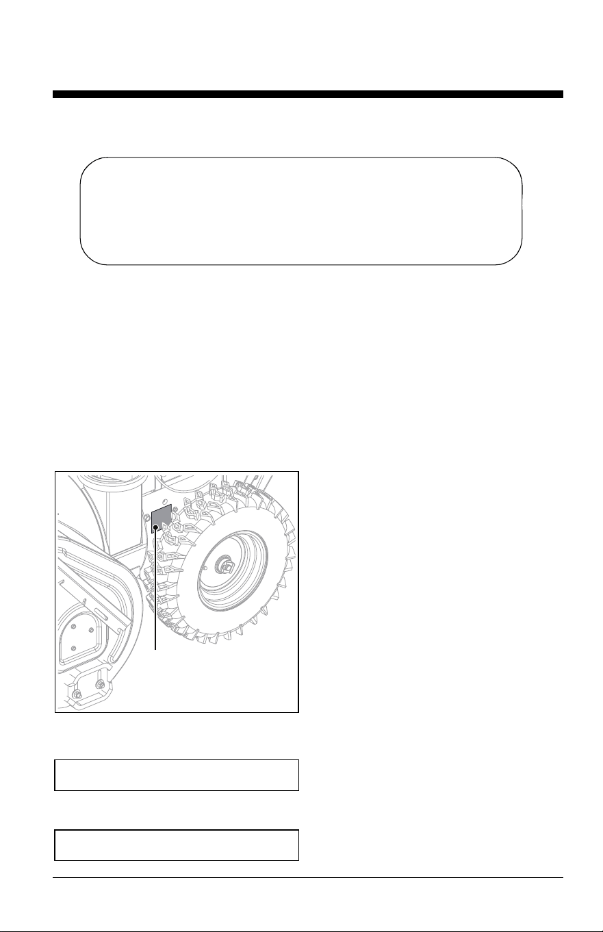
Locate the model and serial number decal on
your unit and register those numbers online
at www.ariens.com. See Figure 1 for decal
location. Be aware that the original selling
dealer may have already completed product
registration on behalf of the original
purchaser.
Record model number here.
Record serial number here.
Figure 1
Model & Serial Number
Decal
MANUALS
Before operating or servicing the unit,
carefully and completely read the manuals
provided with the unit. They contain safety
instructions and important information about
unit controls.
The engine on this unit is covered by a
separate manual. Refer to the engine manual
for engine service recommendations. Contact
the engine manufacturer for a replacement
manual if necessary.
It is your responsibility to read and understand
all safety precautions and instructions in the
manuals. If you do not understand or have
difficulty following the instructions, contact
your Ariens dealer for assistance. To locate
your nearest Ariens dealer, go to
www.ariens.com.
DISCLAIMER
Ariens reserves the right to discontinue, make
changes to, and add improvements upon its
products at any time without public notice or
obligation. The descriptions and
specifications contained in this manual were
in effect at printing. Equipment described in
this manual may be optional. Some
illustrations may not be applicable to your
unit.
Have Questions or Need Assistance?
www.ariens.com
A service manual and a parts manual for your unit are available for free
download or purchase at www.ariens.com.
EN - 2
Read these safety rules and follow them
closely. Failure to follow these rules could
lead to loss of control of unit, severe personal
injury or death to you or bystanders, or result
in damage to property or the machine.
PRACTICES & LAWS
Practice usual and customary safe working
precautions. Learn applicable rules and laws
in your area. Always follow the practices set
forth in this manual.
EMISSION CONTROL SYSTEM
This equipment and/or its engine may include
exhaust and evaporative emissions control
system components required to meet U.S.
Environmental Protection Agency (EPA)
and/or California Air Resources Board
(CARB) regulations. Tampering with emission
controls and components by unauthorized
personnel may result in severe fines or
penalties. Emission controls and components
can only be adjusted by an Ariens dealer or
an authorized engine manufacturer's service
center. Contact your Ariens Equipment
Retailer concerning emission controls and
component questions.
REQUIRED OPERATOR
TRAINING
Read and understand the
Operator's Manual and decals
on the unit. This information is
for your safety and the proper
use of your equipment.
Failure to follow these
instructions and warnings may cause death
or serious injury. If you have purchased this
product from an Ariens dealer, the dealer can
provide you with training.
Familiarize yourself and any other operators
with all controls and the safe use of the
features of this unit. If you loan, rent or sell
this product to others, provide them with all
manuals.
If you have any questions, please call our
customer support line at 920-756-4688 or
contact us at www.ariens.com. Do not use
this equipment if, after reading the Operator's
Manual and the on-board decals, you have
any questions about the safe use of this
product.
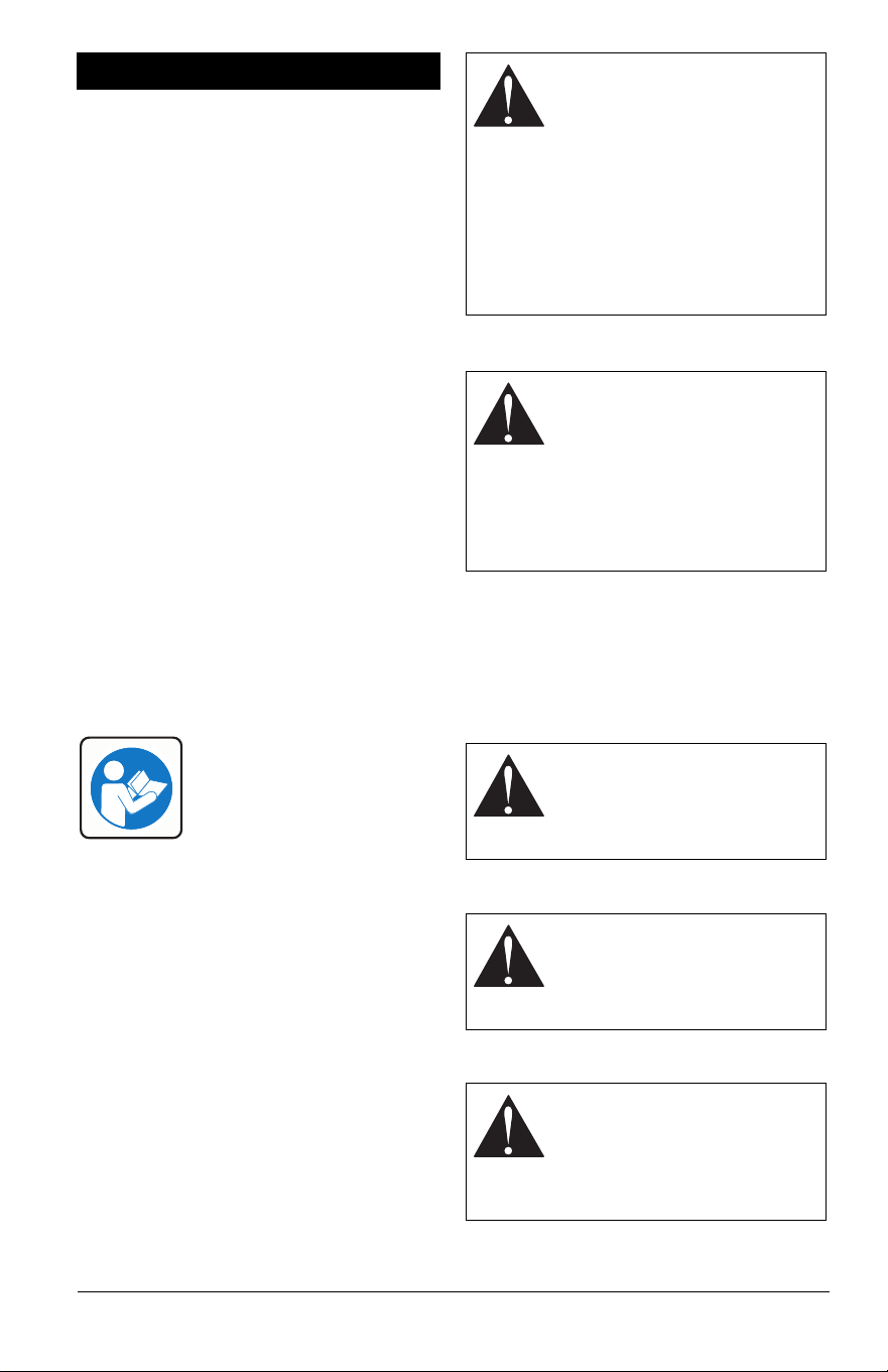
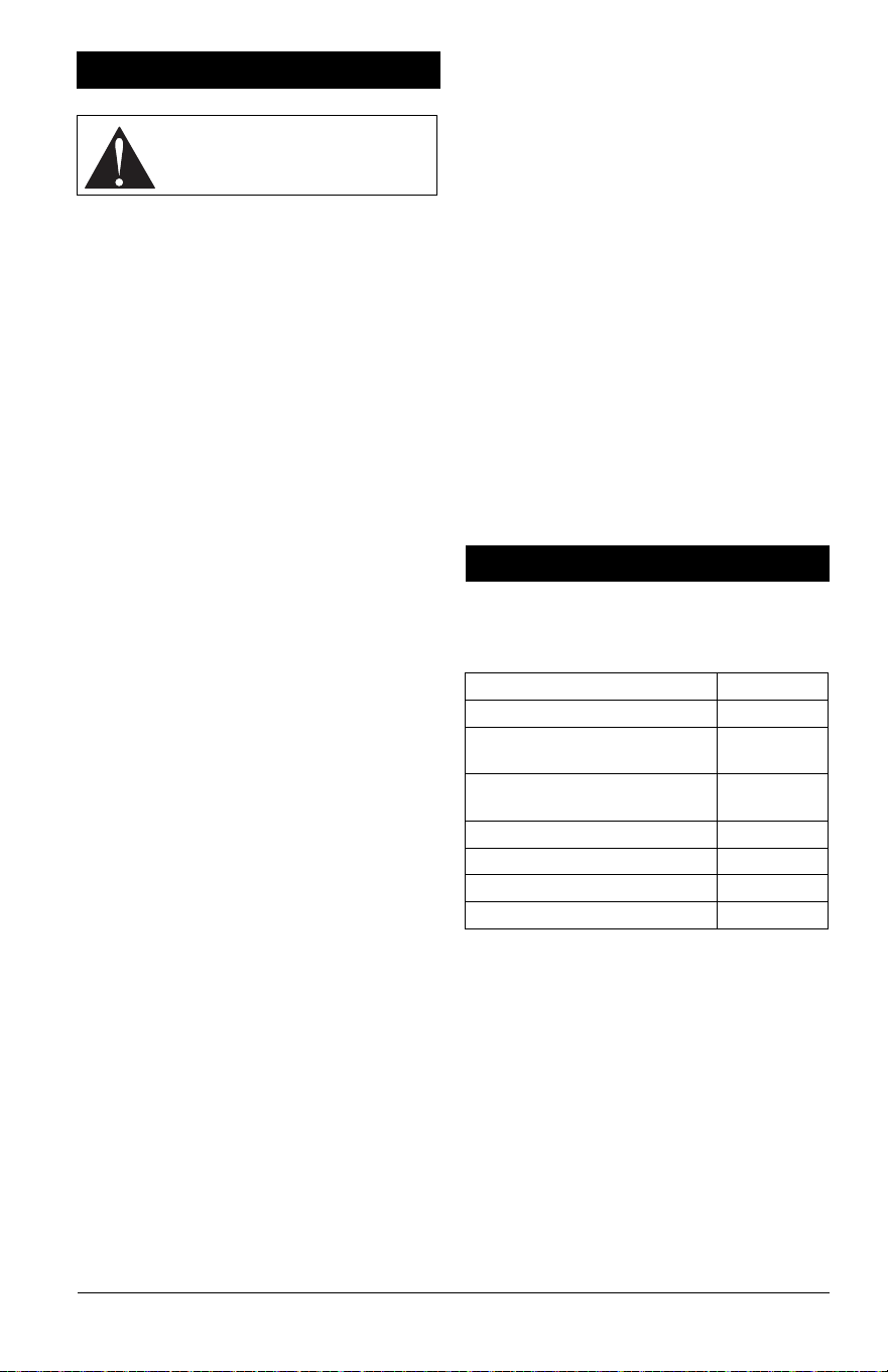
SAFETY ALERT SYMBOL
SIGNAL WORDS
The safety alert symbol above and signal
words below are used on decals and in this
manual. Read and understand all safety
messages.
1. Danger
2. Warning
3. Caution
SAFETY
WARNING: AVOID INJURY.
This snow thrower is capable of
crushing or amputating body
parts. Failure to observe the
safety instructions in the
manuals and on decals could
result in serious injury or death.
ALWAYS disengage auger, stop
unit and engine, remove key and
allow moving parts to stop
before leaving operator’s
position.
This is the safety alert symbol. It
means:
• ATTENTION!
• YOUR SAFETY IS
INVOLVED!
When you see this symbol:
• BECOME ALERT!
• OBEY THE MESSAGE!
DANGER: Indicates an
IMMINENTLY HAZARDOUS
SITUATION! If not avoided,
WILL RESULT in death or
serious injury.
WARNING: Indicates a
POTENTIALLY HAZARDOUS
SITUATION! If not avoided,
COULD RESULT in death or
serious injury.
CAUTION: Indicates a
POTENTIALLY HAZARDOUS
SITUATION! If not avoided, MAY
RESULT in minor or moderate
injury. It may also be used to
alert against unsafe practices.
EN - 3
4. Notice
NOTICE: Indicates information or procedures
that are considered important but not hazard
related. If not followed, property damage
could result.
5. Important
IMPORTANT: Indicates general reference
information worthy of special attention.
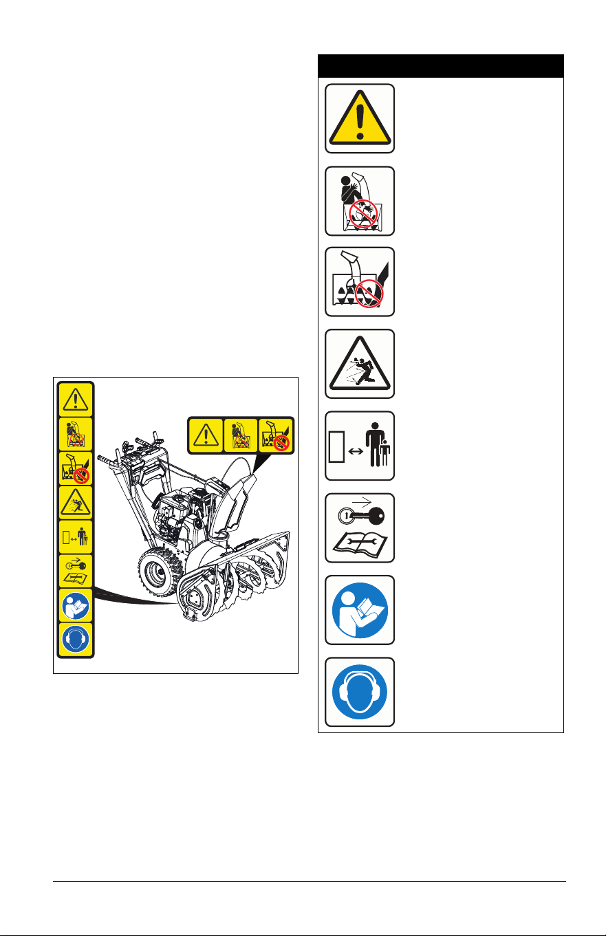
SAFETY DECALS
The safety decals on your machine are visual
reminders of the important safety information
in this manual. All messages on your unit
must be fully understood and carefully
followed. Safety decals on the machine are
explained below.
Always replace missing or damaged safety
decals. Replacement decal information is in
the parts manual for your machine. Decals
can be ordered from your dealer.
See Figure 2 for safety decal locations.
Safety Decal Locations
Safety Decal Descriptions
Figure 2
2
1
1. CAUTION!
Danger!
Only use clean-out tool to
clear blockages. NEVER
use your hands.
High-speed auger/impeller
rotates below discharge
opening. Wait for all moving
parts to stop before
removing clogs or servicing.
NEVER direct discharge
towards persons or property
that may be injured or
damaged by thrown objects.
Keep people away from unit
while operating. Keep
children out of work area
and under watchful care of a
responsible adult.
Stop engine, remove key,
and read manual before
making any repairs or
adjustments.
Read operator’s manual.
Wear appropriate hearing
protection.
EN - 4
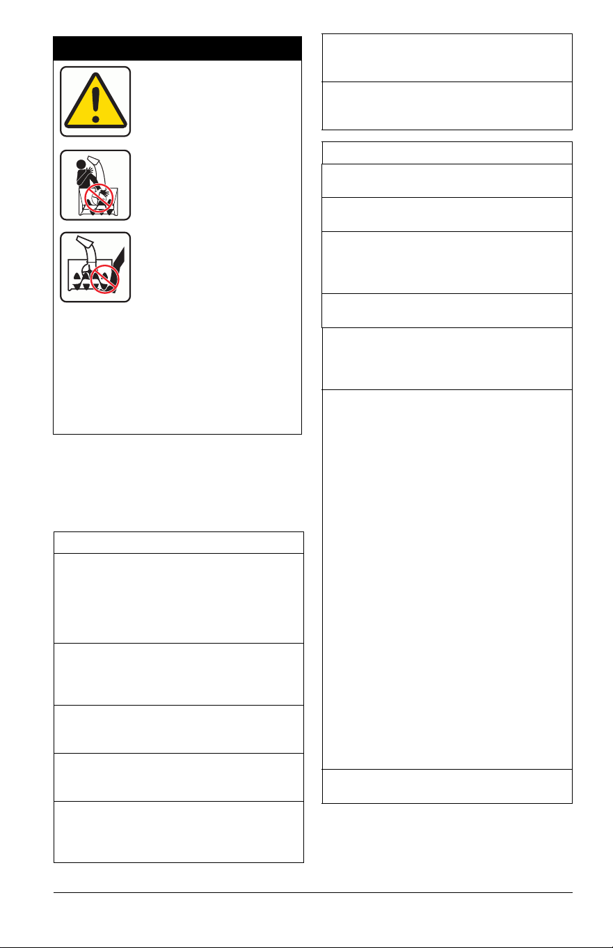
SAFETY RULES
The following safety instructions are based
on the B71.3 specifications of the American
National Standards Institute in effect at the
time of production.
2. DANGER!
Danger!
ROTATING PARTS! Keep
clear of auger while engine
is running.
• Read operator’s manual.
• Allow operation only by
properly-trained adult,
never children.
• Stop engine and remove
ignition key prior to
leaving the operator’s
position for any reason.
• Keep all controls, guards
and safety devices
properly serviced and
functional.
• NEVER direct discharge
towards persons or
property that may be
injured or damaged by
thrown objects.
Training
Read, understand and follow all instructions
on the machine and in the manual(s) before
operating this unit. Be thoroughly familiar
with the controls and the proper use of the
equipment. Know how to stop the unit and
disengage the controls quickly.
Never allow children to operate or play on or
near the equipment. Never allow adults to
operate the equipment without proper
instruction.
Keep the area of operation clear of all
persons, particularly small children. Be alert
and shut off unit if children enter area.
Exercise caution to avoid slipping or falling,
especially when operating the snow thrower
in reverse.
Always remove key and/or wire from spark
plug before assembly, maintenance or
service. Unintentional engine start up can
cause death or serious injury.
Complete a walk-around inspection of the
unit to understand the unit, your work area
and all safety decals.
Understand how to operate all controls, the
functions of all controls and how to STOP in
an emergency.
Preparation
Always check overhead and side clearances
carefully before operation.
Always be aware of traffic when operating
near streets or along curbs.
Thoroughly inspect the area where the
equipment is to be used and remove all
doormats, sleds, boards, toys, wires and
other foreign objects.
Disengage all clutches and shift into neutral
before starting the engine.
Use extension cords and receptacles as
specified by the manufacturer for all units
with electric drive motors or electric starting
motors.
Handle fuel with care; it is highly flammable.
• Use an approved fuel container.
• Never add fuel to a running engine or hot
engine.
• Fill fuel tank outdoors with extreme care.
Never fill fuel tank indoors.
• Never fill containers inside a vehicle or
on a truck or trailer bed with a plastic
liner. Always place containers on the
ground, away from your vehicle, before
filling.
• When practical, remove gas-powered
equipment from the truck or trailer and
refuel it on the ground. If this is not
possible, then refuel such equipment on
a trailer with a portable container, rather
than from a gasoline dispenser nozzle.
• Keep the nozzle in contact with the rim of
the fuel tank or container opening at all
times, until refueling is complete. Do not
use a nozzle lock-open device.
• Replace gasoline cap securely and wipe
up spilled fuel.
• If fuel is spilled on clothing, change
clothing immediately.
Adjust the auger / impeller housing height to
clear gravel or crushed rock surface.

EN - 5
Never attempt to make any adjustments
while the engine is running (except when
specifically recommended by manufacturer).
Always allow unit and engine to adjust to
outdoor temperature before clearing snow.
Operation
Disengage all controls before starting
engine.
Never leave a running unit unattended.
Always stop engine and remove key before
leaving unit to prevent unauthorized use.
Do not put hands or feet near or under
rotating parts. Keep clear of the discharge
opening at all times.
Moving and/or rotating parts can cut off body
parts such as fingers or a hand. NEVER
place your hands, other body part or clothing
near any moving parts while unit is running.
Always keep hands away from all pinch
points.
Do not touch parts which might be hot from
operation. Allow parts to cool before
attempting to maintain, adjust or service.
Thrown objects can cause injury. Check for
weak spots on docks, ramps or floors. Avoid
uneven work areas and rough terrain and
stay alert for hidden hazards.
Exercise extreme caution when operating on
or crossing gravel drives, walks or roads.
Stay alert for hidden hazards or traffic.
After striking a foreign object, stop the
engine, remove the wire from the spark plug,
disconnect the cord on electric motors,
thoroughly inspect the snow thrower for any
damage, and repair the damage before
restarting and operating the snow thrower.
If the unit should start to vibrate abnormally,
stop the engine and check immediately for
the cause. Vibration is generally a warning
of trouble.
Stop the engine whenever you leave the
operating position, before unclogging the
auger / impeller housing or discharge chute,
and when making any repairs, adjustments
or inspections.
When cleaning, repairing or inspecting the
snow thrower, stop the engine and make
certain the auger / impeller and all moving
parts have stopped. Disconnect the spark
plug wire and keep the wire away from the
plug to prevent someone from accidentally
starting the engine.
Do not run the engine indoors, except when
starting the engine and for transporting the
snow thrower in or out of the building. Open
the outside doors; exhaust fumes are
dangerous.
Never operate the snow thrower without
proper guards, and other safety protective
devices in place and working.
Always stand clear of the discharge area
when operating this unit.
Never direct the discharge toward people or
areas where injury or property damage can
occur from thrown objects. Keep children
and others away.
Do not overload the machine capacity by
attempting to clear snow at too fast a rate.
Never operate the machine at high transport
speeds on slippery surfaces. Look behind
and use care when operating in reverse.
Do not operate in reverse unless absolutely
necessary. Always back up slowly and look
down and behind before and while backing.
Do not carry passengers.
Disengage attachment when not in use and
when traveling from one work area to
another.
Disengage power to the auger / impeller
when snow thrower is transported or not in
use.
Use only attachments and accessories
approved by the manufacturer of the snow
thrower (such as wheel weights,
counterweights or cabs).
This product is equipped with an internal
combustion engine. Do not use unit on or
near any unimproved, forest-covered or
brush-covered land unless exhaust system
is equipped with a spark arrester meeting
applicable local, state or federal laws. A
spark arrester, if used, must be maintained
in effective working order by operator.
Never operate the snow thrower without
good visibility or light. Always be sure of
your footing, and keep a firm hold on the
handles. Walk; never run.
Never operate unit after or during the use of
medication, drugs or alcohol. Safe operation
requires complete and unimpaired attention
at all times.
Never allow anyone to operate this unit
when their alertness or coordination is
impaired.
Never touch a hot engine or muffler.

EN - 6
Avoid contact with sharp edges; sharp
edges can cut.
Do not throw snow higher than necessary.
Clearing a Clogged Discharge Chute
Hand contact with the rotating auger /
impeller inside the discharge chute is the
most common cause of injury associated
with snow throwers. Never use your hand to
clean out the discharge chute.
To clear the chute:
1. SHUT THE ENGINE OFF!
2. Wait 10 seconds to be sure the auger /
impeller blades have stopped rotating.
3. Always use a clean-out tool, not your
hands.
Maintenance and Storage
Secure unit so it will not tip over during
maintenance.
Before cleaning, removing clogs or making
any inspections, repairs, etc., disengage
clutch(es), stop engine, remove key, allow
moving parts to stop and hot parts to cool.
Check shear bolts and other bolts at
frequent intervals for proper tightness to be
sure the equipment is in safe working
condition.
Check clutch and brake operation
frequently.
Do not change engine governor settings and
do not over-speed engine.
Adjust and service as required. Motion of
drive wheels and auger / impeller must stop
quickly when clutch levers are released.
Always maintain unit in safe operating
condition. Damaged or worn out muffler can
cause fire or explosion.
Keep unit free of ice or other debris. Clean
up oil or fuel spills.
Always keep protective structures, guards,
and panels in good repair and secured in
place. Never modify or remove safety
devices.
Never store the machine with fuel in the fuel
tank inside a building where ignition sources
are present such as hot water heaters,
space heaters or clothes dryers. Close fuel
valve and allow the engine to cool
completely before storing in any enclosure
or covering the unit.
Always refer to operator's manual for
important details if the snow thrower is to be
stored for an extended period.
Maintain or replace safety and instruction
labels as necessary.
Run the machine a few minutes after
throwing snow to prevent freeze-up of the
auger / impeller.
Personal Protection
Do not operate the equipment without
wearing adequate winter garments. Avoid
loose fitting clothing that can get caught in
moving parts. Wear footwear that will
improve footing on slippery surfaces.
Wear adequate safety gear, including safety
glasses with side shields and protective
gloves.
Do not wear loose clothing or jewelry, and tie
back hair that may get caught in rotating
parts.
NEVER attempt to unclog or clean unit while
engine is running. Rotating auger / impeller
can cause serious injury.
Protect eyes, face and head from objects
that may be thrown from unit. Wear
appropriate hearing protection.
Always wear safety glasses or eye shields
during operation or while performing an
adjustment or repair to protect eyes from
foreign objects that may be thrown from the
machine.
Slope Operation
Exercise extreme caution when operating on
slopes. DO NOT operate on steep slopes.
DO NOT clear snow across the face of
slopes; go up and down. Keep all movement
on slopes slow and gradual.
Use a slow speed to avoid stops or shifts on
slopes. Avoid starting or stopping on a
slope. Do not park unit on a slope unless
absolutely necessary. When parking on a
slope always block the wheels.
Do not operate near drop-offs, ditches, or
embankments. Unit can suddenly turn over if
a wheel is over the edge of a cliff or ditch, or
if an edge caves in.

EN - 7
Fuel
DO NOT run engine in an enclosed area.
Always provide good ventilation. Fumes
from engine exhaust can cause injury or
death.
Fuel is highly flammable and its vapors are
explosive. Handle with care. Use only an
approved gasoline container with an
appropriately-sized dispensing spout.
No smoking, no sparks, no flames. Always
allow engine to cool before servicing.
Never fill fuel tank when engine is running or
hot from operation.
Never fill or drain fuel tank indoors.
Replace fuel cap securely and clean up
spilled fuel.
Never fill fuel containers inside a vehicle or
on a truck or trailer bed with a plastic liner.
Always place containers on the ground away
from your vehicle before filling.
When practical, remove gas-powered
equipment from the truck or trailer and refuel
it on the ground. If this is not possible, then
refuel on a trailer with a portable container,
rather than from a gasoline dispenser
nozzle.
Keep the nozzle in contact with the rim of
the fuel tank or container opening at all
times until fueling is complete. Do not use a
nozzle lock-open device.
If fuel is spilled on clothing, change clothing
immediately.
Properly remove fuel before tipping unit up
onto housing to avoid spills.
Towing/Transporting
Always stop engine, remove key and close
fuel valve or drain fuel when transporting
unit on a truck or trailer.
Use extra care when loading or unloading
unit onto trailer or truck. Secure unit chassis
to transport vehicle. Never secure from rods
or linkages that could be damaged. Do not
transport machine while engine is running.
Accessories
Use only AriensCo-recommended
attachments or accessories that are
designed for your unit and that are
appropriate to your use and can be used
safely in your application.
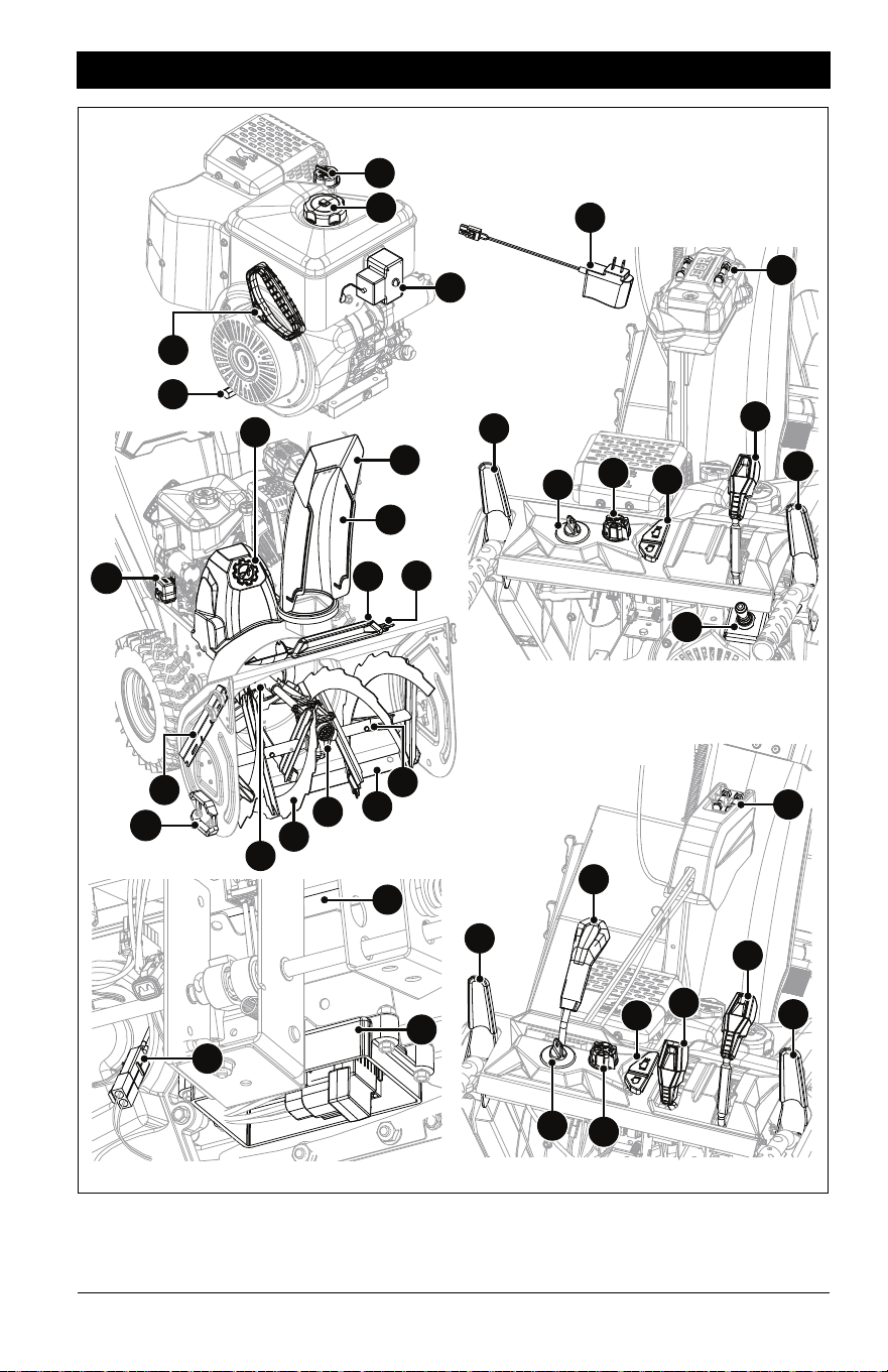

EN - 9
1. Engine Key
2. Fuel Tank and Cap
3. Electric Start Button
4. Throttle Control Knob
5. Oil Fill / Dipstick
6. Oil Drain
7. Recoil Starter Handle
8. Speed Selector Lever
9. Auger
10. Impeller
11. Shear Bolt (2)
12. Replacement Shear Bolts (2)
13. Attachment Clutch Lever
14. Traction Drive Clutch Lever
15. Discharge Chute Rotation Lever (Model
926081)
16. Discharge Chute Deflector Lever (Model
926081)
17. Discharge Chute Control Switch (Model
926091)
18. Heated Hand Grip Switch
19. Scraper Blade
20. Drift Cutter (2)
21. Skid Shoe (2)
22. Snow Clean-out Tool
23. Discharge Chute
24. Discharge Chute Deflector
25. Belt Cover
26. Gearcase
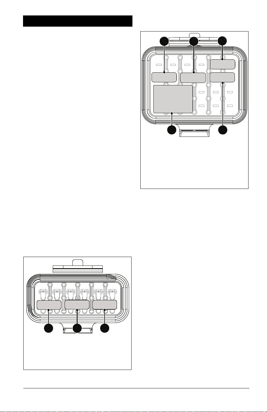
27. Fuse Box
28. ECU (Engine Control Unit)
29. Battery Connector
30. LED Light Bar (Model 926091)
31. EFI Battery – 7.2 V
32. EFI Battery Charger – 7.2 V
EN - 10
See Figure 3 for all controls and features
locations.
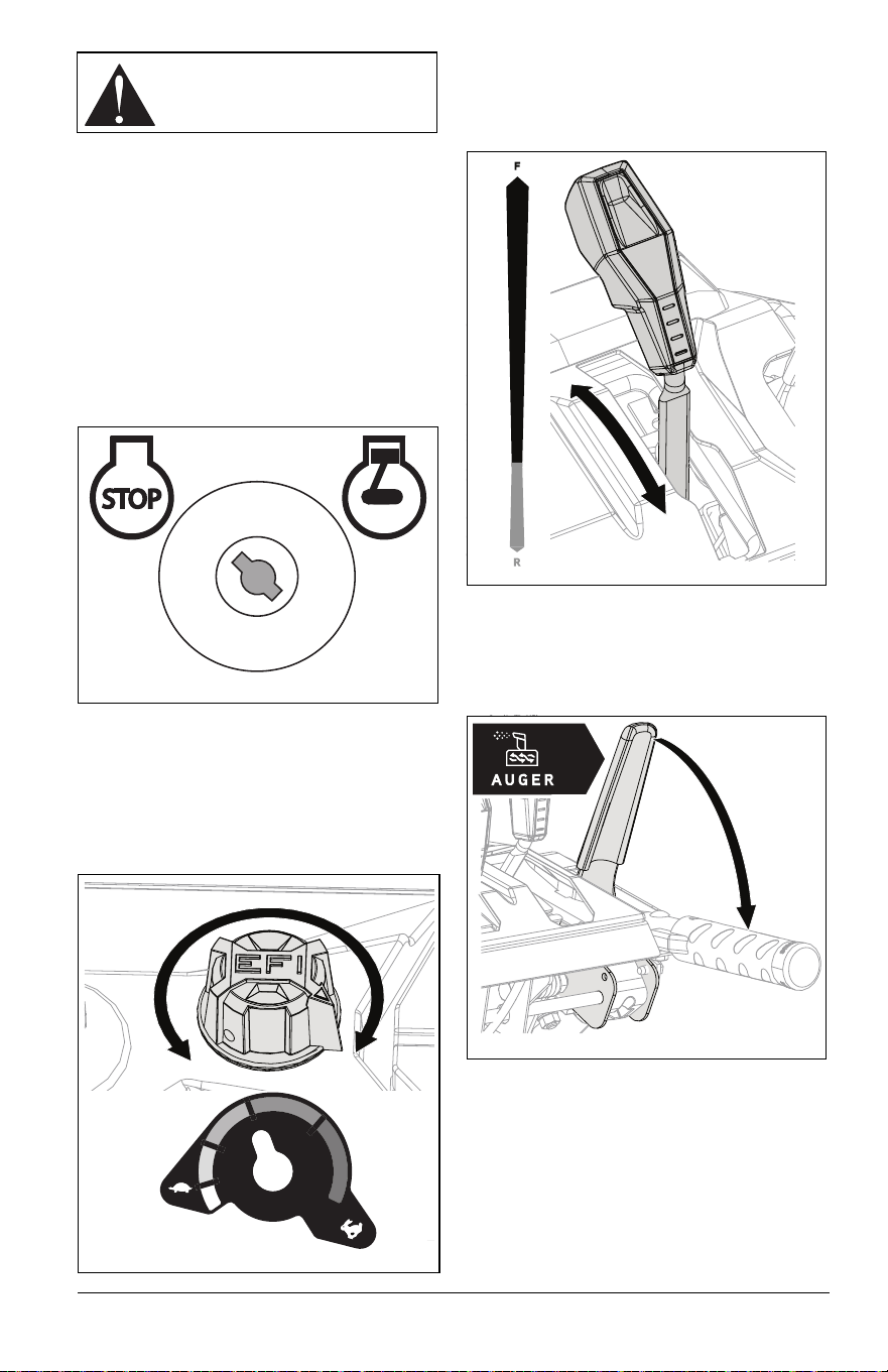
ENGINE KEY
See Figure 6.
Controls power to the engine. The key cannot
be removed when in run position.
NOTICE: ALWAYS turn key to off position
when not operating unit. Leaving key in run
position while unit is not in use will drain
battery and result in a difficult- or no-start
condition.
ELECTRIC START BUTTON
Starts engine.
THROTTLE CONTROL KNOB
See Figure 5.
Controls engine speed.
SPEED SELECTOR LEVER
See Figure 6.
Controls the speed of forward and reverse
travel.
ATTACHMENT CLUTCH LEVER
(RIGHT SIDE)
See Figure 7.
Controls auger / impeller movement.
WARNING: Read and
understand the Safety section
before proceeding.
Figure 4
Stop
Run
O
I
Figure 5
Fast
Slow
Figure 6
Figure 7
EN - 11
TRACTION DRIVE CLUTCH
LEVER (LEFT SIDE)
See Figure 8.
Allows unit to travel forward and in reverse.
DUAL HANDLE INTERLOCK
Allows auger / impeller to rotate without
holding attachment clutch lever continuously.
Auger continues to turn until both clutch
levers are released.
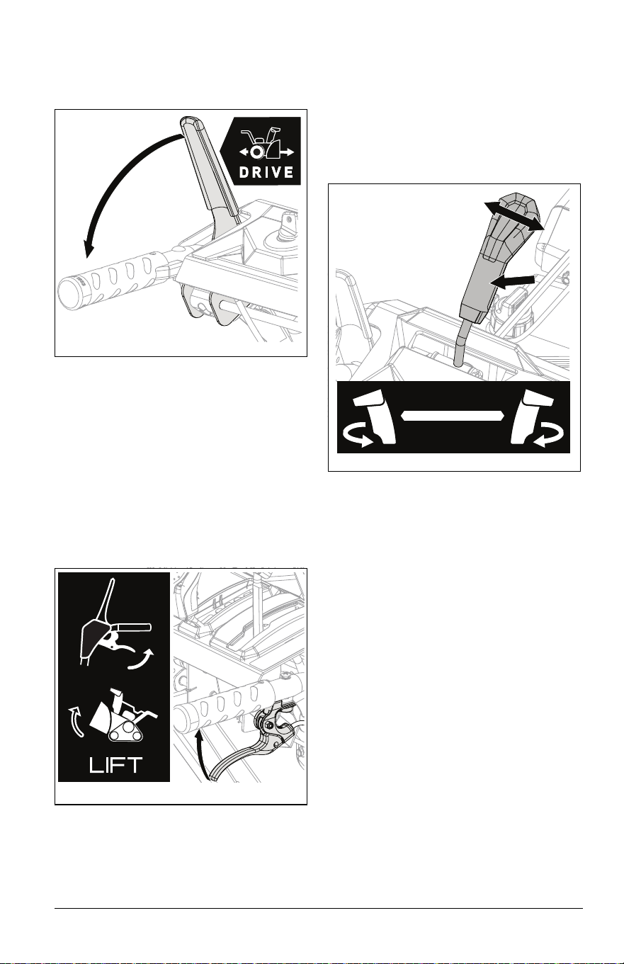
HEIGHT ADJUSTMENT LEVER
(RIGHT SIDE)
Model 926091
See Figure 9.
Raises or lowers auger housing for various
snow-clearing situations.
DISCHARGE CHUTE ROTATION
LEVER
Model 926081
See Figure 10.
Rotates discharge chute to control snow
discharge. Pull lever back to unlock chute,
move lever left or right to desired position,
and then push lever forward to lock chute in
place.
Figure 8
Figure 9
Figure 10
EN - 12
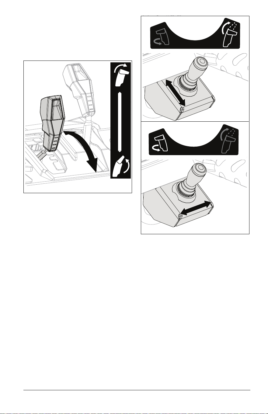
DISCHARGE CHUTE DEFLECTOR
LEVER
Model 926081
See Figure 11.
Moves discharge deflector up or down to
control height of snow discharge.
DISCHARGE CHUTE CONTROL
SWITCH
Model 926091
See Figure 12.
Rotates discharge chute and chute deflector
to control snow discharge. Move control lever
forward or backward to control height of snow
discharge. Move lever left or right to rotate
discharge chute to desired position.
IMPORTANT: Engine must be running for
electric discharge chute to operate.
NOTICE: Model 926091 only: If discharge
chute does not move after operating chute
control switch, DO NOT manually force chute
or hold lever for more than 2 seconds. See
Troubleshooting on page 28.
HEATED HAND GRIP SWITCH
Turns the heated hand grips on and off.
SCRAPER BLADE
Contacts the surface being cleared and
protects the housing from damage during
normal use.
DRIFT CUTTER
Breaks up snow drifts that are taller than the
auger housing and directs snow into auger.
SKID SHOE
Controls the distance between the scraper
blade and the surface.
AUGER
Rotates to bring snow into impeller.
IMPELLER
Throws snow out discharge chute.
Figure 11
Figure 12
EN - 13
SHEAR BOLT
Secures auger to shaft and helps prevent
gearcase and gearcase component damage.
AUTO-TURN™ STEERING
Automatically locks or unlocks wheels or
tracks to allow unit to turn more precisely.
IMPORTANT: All references to left, right, front
or rear are given from the perspective of
operator in operator’s position, facing the
direction of forward travel.
EMERGENCY STOPPING
1. Release both clutch levers.
2. Turn engine key to stop position and
remove key.
3. Wait for all moving parts to stop before
leaving operator’s position.
BEFORE OPERATING UNIT
IMPORTANT: Register your product! See
Register Your Product! on page 1.
1. Check for a frozen impeller.
a. Turn engine key to stop position and
remove key.
b. Engage attachment clutch lever and
pull recoil starter handle.
c. If handle does not pull, move unit to a
warm area to thaw.
2. Check fuel level and add fuel if needed.
IMPORTANT: Use fresh unleaded fuel with
an octane rating of at least 87. DO NOT use
E85 blended fuels; the engine is not E20 /
E30 / E85 compatible. The maximum
recommended ethanol content is 10%. Ariens
recommends using a quality fuel stabilizer in
all fuel. See Short Term on page 30.
3. Check engine oil level and add oil if
needed. Refer to engine manual.
4. Check function of controls.
• Attachment Clutch Lever
• Traction Drive Clutch Lever
• Dual Handle Interlock
5. Know how to stop in an emergency. See
Emergency Stopping on page 13.
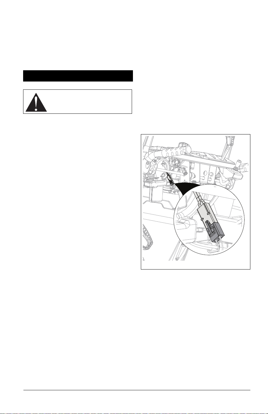
START THE ENGINE
IMPORTANT: The unit is shipped with the
EFI battery disconnected. The EFI battery
MUST be connected to start and run the
engine.
IMPORTANT: Engine can be started with
throttle in any position.
1. Electric Start: Connect power cord to
starter and then into 120V 3-wire
grounded outlet.
IMPORTANT: Use a power cord that is UL
listed or CSA certified, rated for a minimum of
13 amps, grounded and labeled as suitable
for outdoor use.
2. Ensure the EFI battery located under the
control panel is connected and fully
charged. See Figure 13.
3. Insert engine key and turn to run position.
4. Electric Start: Press electric start button.
NOTICE: DO NOT run starter more than 10
times at intervals of 5 seconds on / 5 seconds
off or overheating and damage may occur.
5. Recoil Start: Pull recoil starter handle.
a. Grasp handle and pull rope out slowly
until it pulls harder.
b. Pull handle firmly and quickly with a
rapid, continuous full-arm stroke.
Repeat until engine starts. If engine
does not start, see Troubleshooting
on page 28.
c. Let handle rewind slowly after engine
starts. DO NOT let handle snap
against engine.
OPERATION
WARNING: AVOID INJURY.
Read and understand the Safety
section before proceeding.
Figure 13
EN - 14
6. Electric Start: Disconnect power cord
from outlet and then from starter.
OPERATE UNIT
1. Rotate discharge chute and move
deflector to desired positions.
2. Select desired speed.
3. Engage attachment clutch.
IMPORTANT: For best snow-throwing
results, ensure the throttle control knob is set
to the high position.
NOTICE: Stop auger when traveling between
work areas.
4. Engage traction drive clutch.
IMPORTANT: When the unit is turned left or
right, the Auto-Turn
TM
differential
automatically unlocks wheels or tracks for
easier turning. On a straight path, the
differential locks both wheels or tracks in
place for best traction.
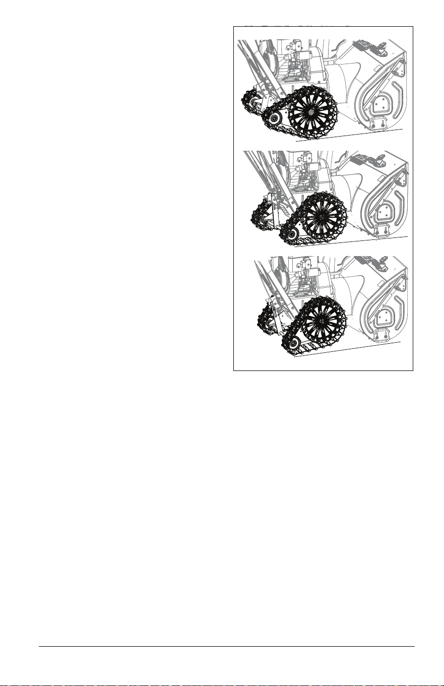
Adjust Track Angle
Model 926091
See Figure 14.
• Wheel Operation: Allows for maximum
maneuverability and ease of turning for
locations not requiring high traction.
Squeeze height adjustment lever and push
down on handlebar. Release lever to latch
rear track idlers in raised position.
• Track Operation: Allows for maximum
traction and keeps auger housing level
when clearing deep or wet snow. Squeeze
and release height adjustment lever.
• Digger Operation: Clears packed snow.
Squeeze height adjustment lever and lift up
on handlebar. Release lever to latch rear
track idlers in lowered position.
Figure 14
Wheel
Track
Digger
EN - 15
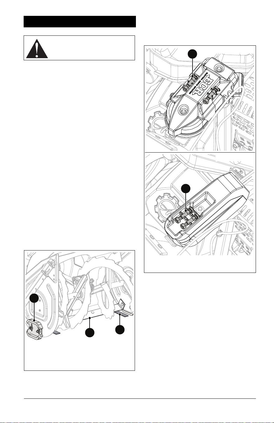
Position Drift Cutters
Use drift cutters if snow to be cleared is
higher than auger housing.
1. Loosen wing knobs and move drift cutter
down. See Figure 15.
See Figure 16.
2. Rotate drift cutter forward 180 degrees
until notch engages upper wing knob.
Tighten wing knobs.
3. Repeat on other side.
Clear a Clogged Discharge Chute
1. Stop engine, remove key and wait for all
moving parts to stop and for hot parts to
cool.
2. Use the snow clean-out tool to clear the
clog.
3. Return the tool to its storage position on
the auger housing.
STOP THE ENGINE
1. Release traction drive clutch lever.
2. Run auger / impeller for a few minutes to
remove loose or melting snow to prevent
impeller from freezing.
3. Release attachment clutch lever.
4. Turn throttle control knob to the slow
position.
5. Turn engine key to stop position and
remove key.
MOVE UNIT MANUALLY
See Figure 17.
• To disengage transmission and move unit
with the engine off, pull the bypass rod
outward.
• Push the rod in to engage the transmission
for normal operation.
TRANSPORT UNIT
1. Stop engine and remove key.
2. Secure unit chassis to transport vehicle.
NOTICE: NEVER secure from rods or
linkages that could be damaged.
Figure 15
Figure 16
WARNING: NEVER use your
hand to clean out discharge
chute.
Normal
Operation
Move Unit
Manually
Figure 17
EN - 16
ENGINE OPERATION ANGLE
Engine angle during operation can affect how
well the engine is lubricated regardless of oil
level.
Operating beyond the engine manufacturer’s
recommended maximum angle will lead to
premature engine wear and void the engine
warranty. Refer to the engine operator’s
manual for maximum angle of operation.
Your Ariens dealer can provide service and
adjustments to keep your unit operating at
peak efficiency. Contact an authorized engine
manufacturer’s service center for engine
service.
SERVICE POSITION
See Figure 18.
MAINTENANCE SCHEDULE
SERVICE PARTS
See your Ariens dealer to purchase service
parts for your unit.
MAINTENANCE
WARNING: Read and
understand the Safety section
before proceeding.
WARNING: AVOID INJURY.
Properly remove fuel before
tipping unit up onto housing to
avoid spills. (Refer to engine
manual for instructions.) Make
sure unit is secure and will not tip.
Figure 18
Service Performed
Each Use
Every 5 hrs.
Every 25 hrs.
Annually
As Needed
Add Fuel Stabilizer *
Check Attachment Drive
Clutch Operation
•
Check Traction Drive Clutch
Operation
•
Check Dual Handle
Interlock
•
Check Fasteners •
Check Tire Pressure
(Model 926081)
••
Check Engine Oil •
Change Engine Oil ** • •
Replace Spark Plug ** •
General Lubrication • •
Check Auger Gearcase Oil • •
Charge Battery ‡
Replace Fuel Filter •
* See Add Fuel Stabilizer on page 17.
** Refer to engine manual for instructions.
‡ See Charge Battery on page 20.
NOTICE: The transmission is lubricated for
life and does not require maintenance or
level checking.
Description Part No.
Ariens Hi-Temp Grease – 414
ml (14 oz) cartridge (1)
00036700
Ariens L3 Lube – 237 ml (8 oz) 00068800
Shear Bolt and Nut 52100100
Fuel Stabilizer – 118 ml
(4 oz)
04730400
Gearcase Seal Washer 06400920
Ariens 5W-30 Engine Oil
• 473 ml (16 oz)
• 946 ml (32 oz)
00091000
00067600
Ariens 0W-30 Synthetic
Engine Oil
• 591 ml (20 oz)
• 946 ml (32 oz)
00077600
00077900
Fuse – 5 Amp (Battery) 05076400
EN - 17
ADD FUEL STABILIZER
Add fuel stabilizer to gasoline at time of
purchase to help ensure the best
performance over the life of that fuel. See
Short Term on page 30 for instructions.
CHECK DUAL HANDLE
INTERLOCK
1. Stop engine.
2. Engage attachment clutch and then the
traction drive clutch.
3. Release the attachment clutch lever. The
attachment clutch should stay engaged
until the traction drive clutch lever is
released.
IMPORTANT: If dual handle interlock does
not operate correctly, repair as directed in the
service manual for your unit.
CHECK FASTENERS
Check for loose hardware.
CHECK CLUTCH OPERATION
• Auger / impeller must stop within 5 seconds
when attachment clutch lever is released.
• Wheels or tracks must stop quickly when
traction drive clutch lever is released.
IMPORTANT: If clutches do not engage or
disengage correctly, see Adjust Attachment
Clutch & Brake on page 23 or Adjust Traction
Drive Clutch on page 25. Refer to the service
manual for your unit for more information
about clutch repairs.
CHECK TIRE PRESSURE
Model 926081
Keep tires inflated to pressure listed on tire
sidewall.
CHECK ENGINE OIL
NOTICE: Engine oil level must be maintained
at correct level or engine damage may occur.
Refer to engine manual.
CHANGE ENGINE OIL
Refer to engine manual.
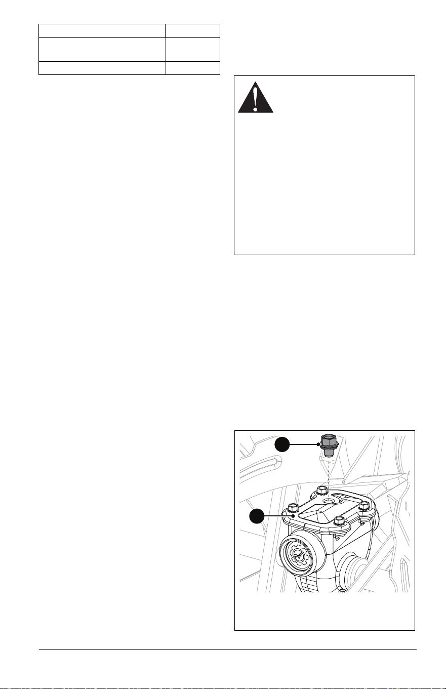
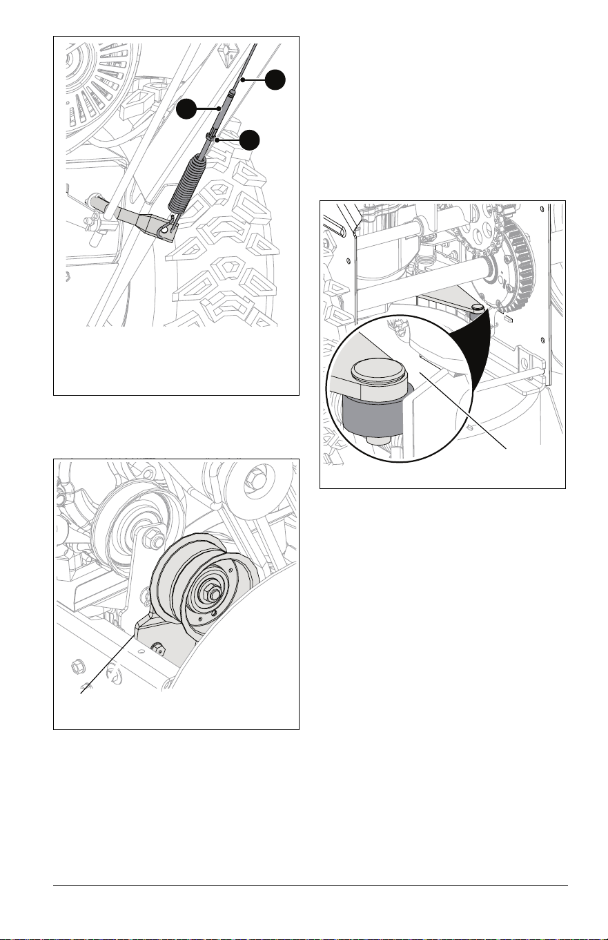
CHECK AUGER GEARCASE OIL
1. Place unit on flat, level surface.
2. Remove oil fill plug and seal washer. See
Figure 19.
IMPORTANT: DO NOT remove gearcase
cover.
Fuse – 7.5 Amp
(Handwarmers & Headlight)
04954200
Relay 04438400
Description Part No.
WARNING: AVOID INJURY.
Explosive separation of tire and
rim parts is possible.
• DO NOT inflate tires above
the recommended pressure.
• DO NOT inflate tires with a
compressor; use a hand
pump.
• DO NOT stand in front of tire
assembly when inflating. Use
a clip-on chuck and extension
hose long enough to allow you
to stand to one side.
• DO NOT mount a tire without
proper equipment and
experience.
1. Auger Gearcase Cover
2. Oil Fill Plug
1
2
Figure 19
EN - 18
3. Check oil level with suitable measuring
device, such as a clean screwdriver, and
add oil if needed. Oil level must be
6.1 cm – 6.7 cm (2.4" – 2.6") from the flat
surface of the gearcase cover.
IMPORTANT: Ariens recommends using only
Ariens L3 synthetic severe duty gear lube
(see Service Parts on page 16). Using other
lubricants will not automatically void unit
warranty, but the warranty will not cover
damage caused by using unauthorized
lubricants.
4. Inspect seal washer for wear or rubber
deterioration and replace if needed.
5. Reinstall seal washer (rubber side down)
and oil fill plug. Torque to 9 N•m
(80 lb-in).
NOTICE: DO NOT over torque.
Measurements are given in pound force
inches (lb-in) and not pound force foot (lb-ft).
Incorrect torquing and failure to install or
correctly torque seal washer may void
gearcase warranty.
LUBRICATE UNIT
Ariens recommends using Ariens Hi-Temp
Grease or equivalent (see Service Parts on
page 16) to lubricate fittings. Lubricate each
season or every 25 hours of operation.
IMPORTANT: Wipe each fitting clean before
and after lubrication.
Remove Bottom Cover
Model 926081
1. Place unit in service position (see
Figure 18).
2. Remove six hex bolts retaining cover and
remove cover. Save for reinstallation.
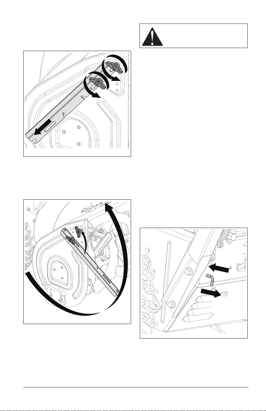
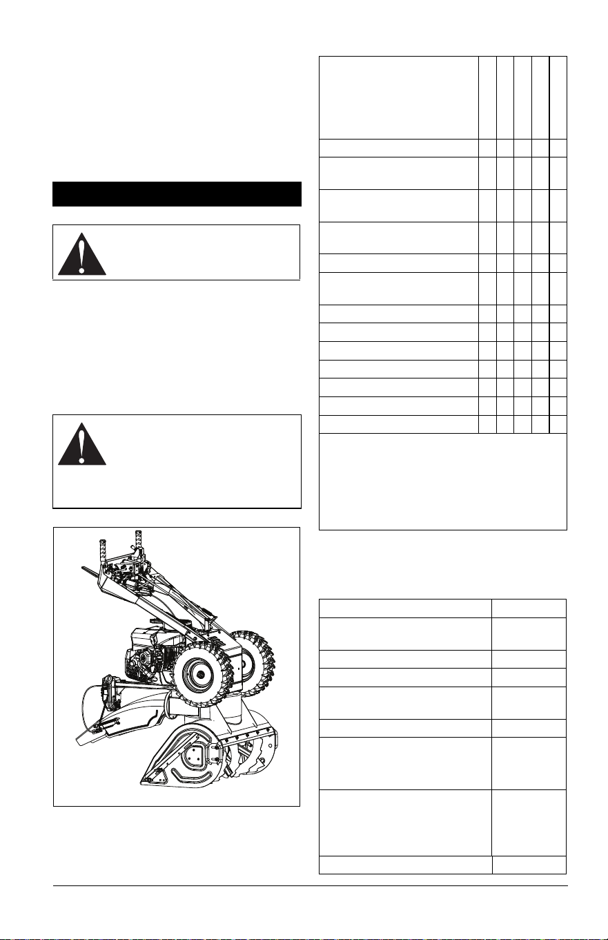
Model 926091
See Figure 20.
1. Place unit in service position (see
Figure 18).
2. Remove three top-lock flange nuts
retaining height-adjuster plate to height-
adjuster bracket.
3. Remove height-adjuster plate and three
spacers on the round head square neck
bolts. The height-adjuster stop will be
attached to the rear axle.
4. Slide height-adjuster stop to the right and
rotate it away from frame.
5. Remove six bolts retaining bottom cover
and remove cover. Rotate track carriage
as needed to remove cover.
Lubricate Unit
Use the following key for all lubrication
procedures.
1. Lubricate as shown in Figures 21, 22 and
23. Refer to the service manual for track
wheel removal instructions. Reinstall
bottom cover and return unit to operating
position.
CAUTION: AVOID INJURY.The
track carriage will rotate freely
without the height-adjuster
bracket. Keep fingers and hands
away from pinch points.
1. Top-lock Flange Nut
2. Height Adjuster Plate
3. Height Adjuster Stop
4. Bottom Cover
5. Rear Axle
2
5
4
1
3
Figure 20
* = Lubricate on Both Sides
Grease
Oil
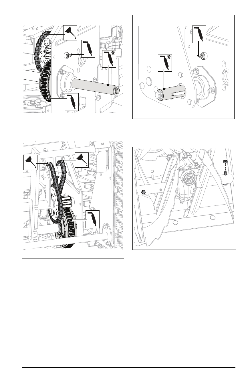
EN - 19
Lubricate Auger Shaft
1. Remove shear bolt nuts and bolts. See
Figure 24.
Figure 21
Model 926081
Figure 22
Model 926091
Figure 23
Model 926091
Figure 24
EN - 20
2. Apply grease at the grease zerks. See
Figure 25.
3. Hand rotate auger on auger shaft.
4. Align shear bolt holes in auger with shear
bolt holes in shaft.
5. Insert bolts through holes.
6. Secure bolts with nuts.
7. Tighten bolts to 7.9 N•m – 16.5 N•m
(5.8 lb-ft – 12.2 lb-ft). If a torque wrench is
unavailable, tighten bolts until they no
longer spin freely. DO NOT overtighten.
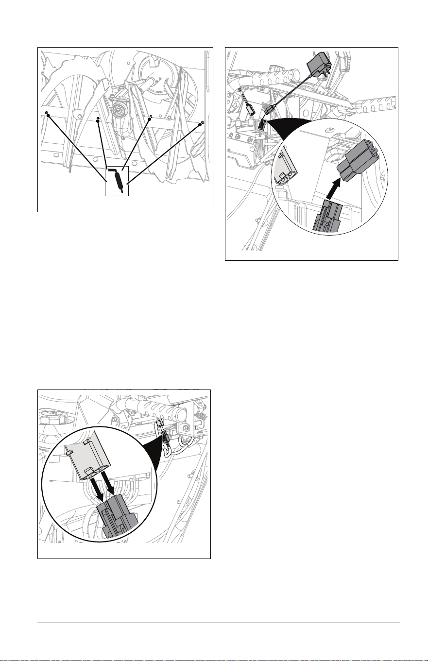
CHARGE BATTERY
IMPORTANT: Snowblower charges battery
when in use if at high engine speed.
1. Disconnect battery connector. See
Figure 26.
IMPORTANT: Battery charger is shipped in
the literature pack.
2. Connect battery connector to charger.
See Figure 27.
3. Plug charger into outlet.
4. Reconnect battery connector when
battery is ready for use. See Figure 26.
IMPORTANT: Battery and charger are each
7.2 volts.
NOTICE: Read through all battery and
charger information below before charging
battery.
Battery and Charger
• Only use supplied charger for battery.
• Do not charge battery longer than 48 hours.
• Fully charge battery before initial use and
any time replacement is installed.
• Battery should be charged every 3 months
while in storage.
• If battery becomes warm to the touch
during charging, disconnect battery from
charger immediately.
• Disconnect battery when charger light turns
green; battery is ready for use.
• Do not use charger in moist or wet
conditions.
• Unplug charger when not in use.
• Never leave charger/battery unattended
while charging.
• If wires become frayed, discontinue use
and replace immediately.
• If plastic connector is broken, discontinue
use and replace immediately.
• Dispose of old battery according to state or
local laws.
Figure 25
Figure 26
Figure 27
EN - 21
ADJUST SCRAPER BLADE
The auger housing may be damaged if blade
wears down too much.
1. Tip unit back onto handlebar, support
auger housing and loosen nuts retaining
blade.
2. Lower blade and tighten nuts.
3. Adjust skid shoes. See Adjust Skid Shoes
on page 21.
NOTICE: ALWAYS adjust skid shoes after
adjusting blade to prevent premature wear of
blade and auger housing damage.
ADJUST SKID SHOES
See Figure 28.
1. Place unit on a hard, flat surface.
2. Place a spacer under each scraper blade
end.
• Use two 3 mm (1/8") thick spacers for
hard, smooth surfaces.
• Use two 22 mm (7/8") thick spacers for
uneven or gravel surfaces.
3. Loosen skid shoe hardware and lower
skid shoes to contact surface. Adjust both
shoes equally.
4. Tighten skid shoe hardware.
REPLACE SHEAR BOLTS
Replace shear bolts if obstruction stops auger
rotation and shear bolts break. See
Figure 29.
IMPORTANT: Ariens recommends using only
Ariens OEM shear bolts when replacing
shear bolts. See Service Parts on page 16.
See Figure 24.
1. Align shear bolt holes in auger with shear
bolt holes in the shaft.
2. Insert bolts through holes.
3. Secure bolts with nuts.
4. Tighten bolts to 7.9 N•m – 16.5 N•m
(5.8 lb-ft – 12.2 lb-ft). If a torque wrench is
unavailable, tighten bolts until they no
longer spin freely. DO NOT overtighten.
ADJUSTMENTS
WARNING: AVOID INJURY.
Read and understand the Safety
section before proceeding.
Figure 28
1. Skid Shoe
2. Spacer
3. Scraper Blade
1
3
2
Figure 29
1. Replacement Shear Bolts
1
Model 926081
Model 926091
1
EN - 22
ADJUST DISCHARGE CHUTE
DEFLECTOR
Model 926081
See Figure 30.
If deflector does not stay in selected position,
tighten the nut under the control panel.
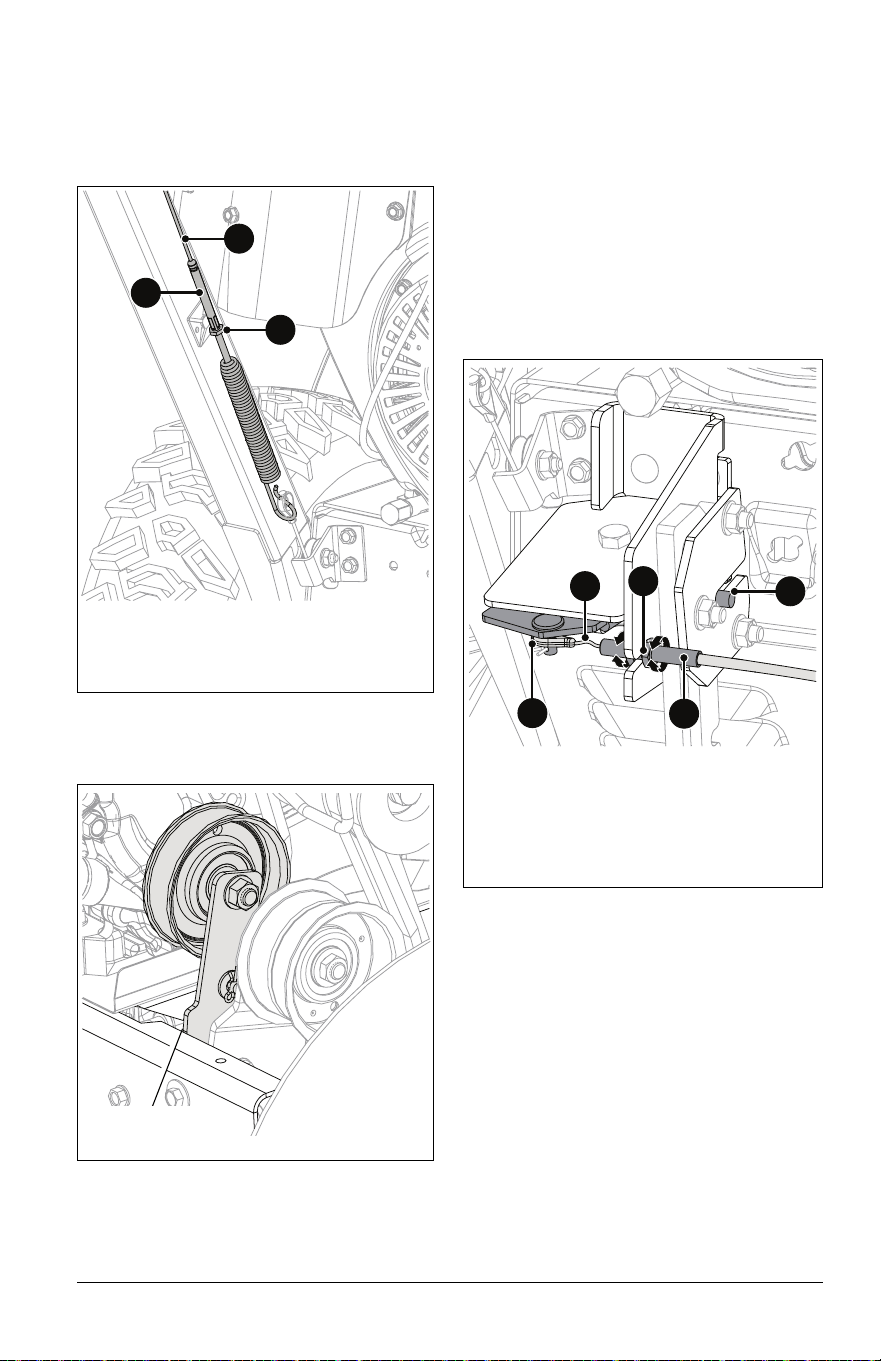
If deflector does not follow full range of travel:
1. Position deflector control in the rear-most
position.
2. Adjust nuts on chute cable. See
Figure 31.
• To adjust deflector lower, loosen lower
nut and tighten upper nut.
• To adjust deflector higher, loosen upper
nut and tighten lower nut.
ADJUST DISCHARGE CHUTE
Model 926081
See Figure 32.
If discharge chute does not stay in selected
position:
1. Remove discharge chute gear cover.
2. Loosen rear adjustment nut and tighten
forward adjustment nut until the lock arm
engages the gear teeth.
3. Reinstall gear cover.
If discharge chute does not rotate freely:
1. Remove discharge chute gear cover.
2. Loosen forward adjustment nut and
tighten rear adjustment nut until there is
no cable slack and the lock arm engages
the gear teeth.
3. Reinstall gear cover.
Figure 30
Figure 31
1. Chute Cable
2. Upper Adjustment Nut
3. Lower Adjustment Nut
1
3
2
EN - 23
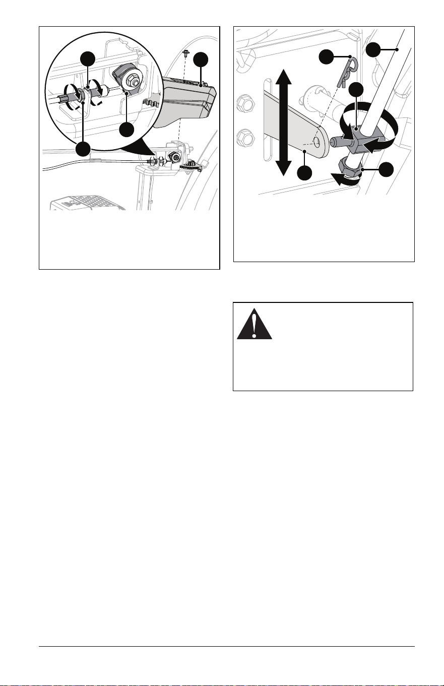
ADJUST SPEED SELECTOR
LEVER
See Figure 33.
1. Place unit on blocks with wheels / tracks
off the ground.
2. Remove hairpin from trunnion and
remove trunnion from bell crank.
3. Loosen jam nut on shift rod.
4. Start the engine and engage the traction
drive clutch.
5. Move the bell crank to the position at
which the wheels / tracks stop moving
and then stop the engine.
6. Move the speed selector lever to neutral
position and hold lever in place.
7. Without moving the bell crank, thread
trunnion up or down the shift rod to align
with bell crank hole.
8. Insert trunnion in bell crank.
9. Reinstall hairpin in trunnion.
10. Tighten jam nut against trunnion.
11. Lower unit to ground.
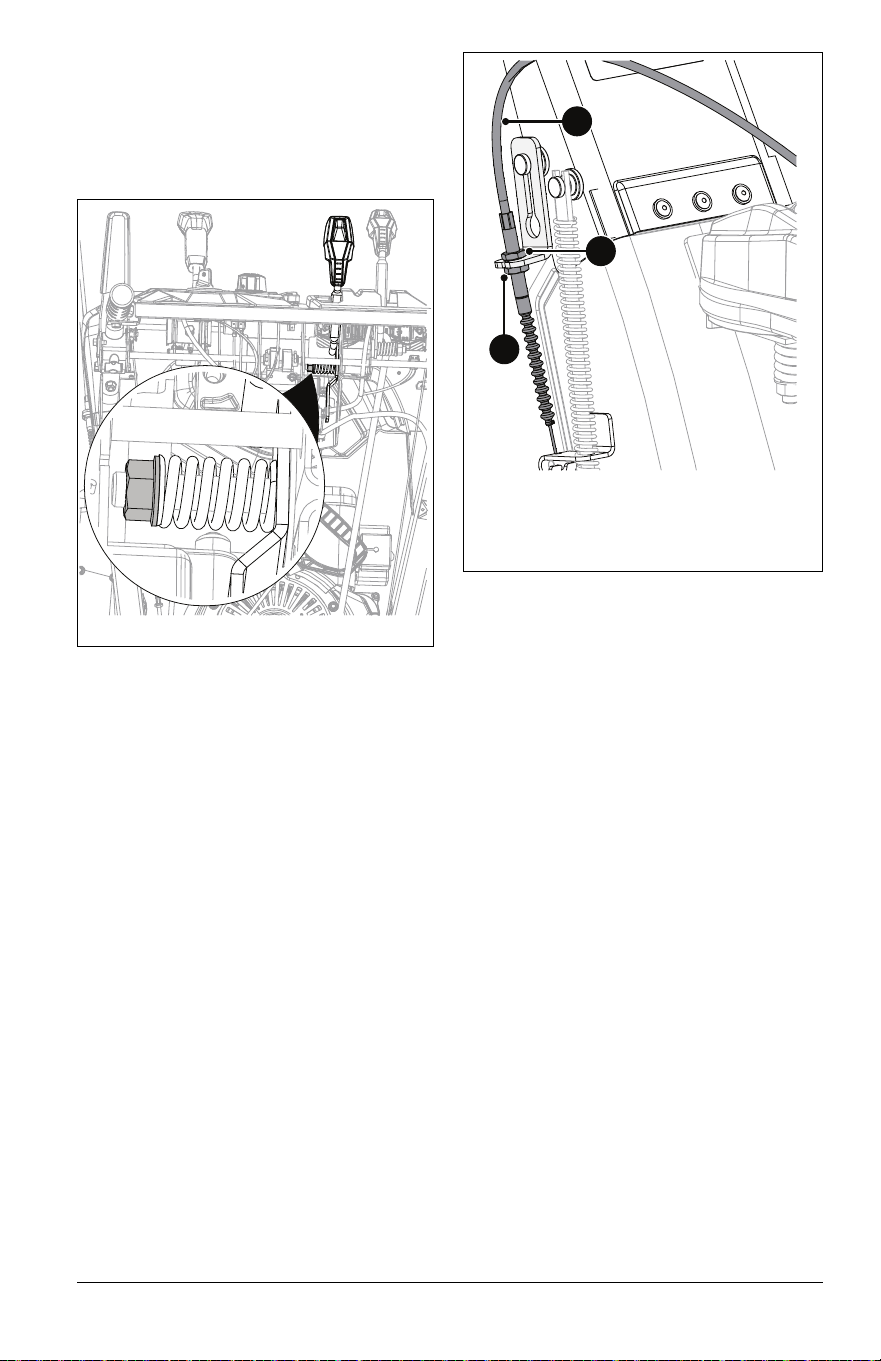
ADJUST ATTACHMENT CLUTCH
& BRAKE
Remove Slack from Attachment
Cable
1. Stop engine, remove key and wait for all
moving parts to stop and for hot parts to
cool.
2. Disconnect spark plug wire.
3. Loosen hardware securing belt cover to
unit and remove belt cover.
IMPORTANT: DO NOT completely remove
hardware from unit.
4. Loosen jam nut on cable adjustment
barrel, and then turn the adjustment
barrel down to shorten cable and remove
cable slack. See Figure 34.
1. Discharge Chute Gear Cover
2. Rear Adjustment Nut
3. Forward Adjustment Nut
4. Lock Arm
1
2
3
4
Figure 32
WARNING: AVOID INJURY.
Improper adjustment could
result in unexpected movement
of auger and impeller causing
death or serious injury. AUGER /
IMPELLER MUST STOP within
5 seconds when attachment
clutch lever is released.
1. Hairpin
2. Trunnion
3. Bell Crank
4. Jam Nut
5. Shift Rod
1
2
5
3
4
Figure 33
EN - 24
5. With the attachment clutch disengaged,
make sure auger idler arm lightly touches
the frame. See Figure 35.
6. Tighten jam nut on cable adjustment
barrel. See Figure 34.
7. Reinstall belt cover and tighten hardware.
8. Reconnect spark plug wire.
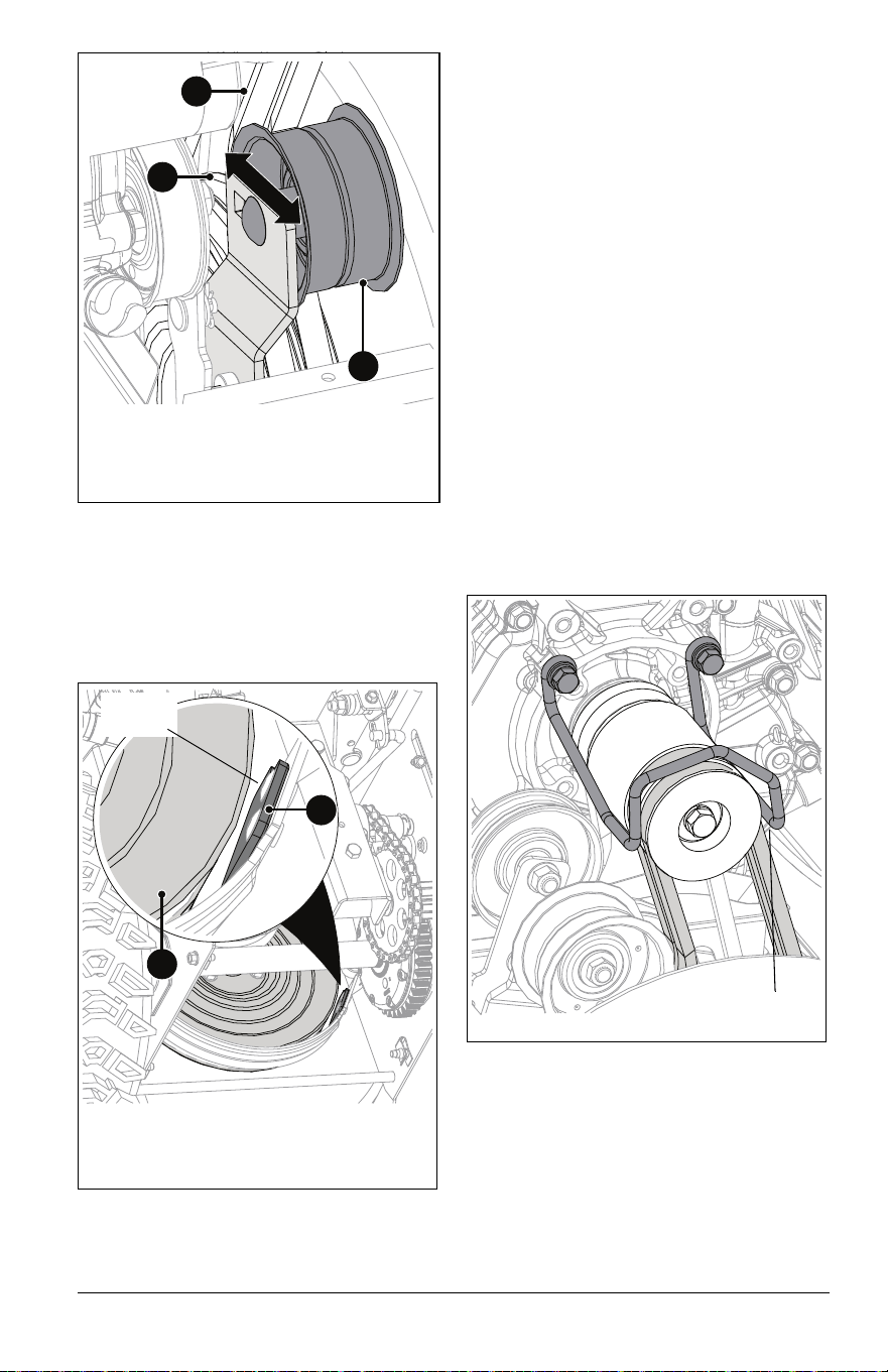
Check Attachment Idler Arm Roller
Clearance
1. Place unit in service position and remove
bottom cover. See Service Position on
page 16.
2. Engage attachment clutch and check
the clearance between the frame and
plastic roller on the lower end of the
attachment idler arm. Roller should be
12.7 mm – 22.2 mm (1/2" – 7/8") from the
frame. See Figure 36.
• If roller is 12.7 mm – 22.2 mm (1/2" –
7/8") from frame, no further adjustment
is required.
See Figure 37.
• If roller is less than 12.7 mm (1/2") from
frame, loosen idler adjustment nut and
move idler closer to belt. Tighten
adjustment nut and recheck roller
clearance.
• If roller is more than 22.2 mm (7/8")
from frame, loosen idler adjustment nut
and move idler away from belt. Tighten
adjustment nut and recheck roller
clearance.
Figure 34
1. Attachment Clutch Cable
2. Cable Adjustment Barrel
3. Jam Nut
3
2
1
Figure 35
Check position
here.
Figure 36
Measure
here.
EN - 25
Check Attachment Brake
With the attachment clutch disengaged,
brake pad must contact attachment belt or
pulley, whichever is closest. With attachment
clutch engaged, brake pad must be a
minimum of 1.6 mm (1/16") from belt or
pulley. See Figure 38.
• If there is less than 1.6 mm (1/16") gap,
loosen idler adjustment nut and move idler
away from belt or pulley. Position idler to
achieve a 1.6 mm (1/16") minimum brake
pad gap and a 12.7 mm – 22.2 mm (1/2" –
7/8") gap between the plastic roller and the
frame. See Figure 37.
IMPORTANT: If adjustments cannot be
brought into specified ranges, see your
dealer for repair.
Check Belt Finger Clearance
See Figure 39.
With attachment clutch engaged, the belt
finger located opposite the belt idler must be
less than 3.2 mm (1/8") from belts, but must
not touch the belts.
To adjust belt finger:
1. Remove belt cover.
2. Loosen bolts and move belt finger to
correct position.
3. Engage attachment clutch.
4. Tighten bolts and recheck belt finger
clearance.
5. Reinstall belt cover and tighten hardware.
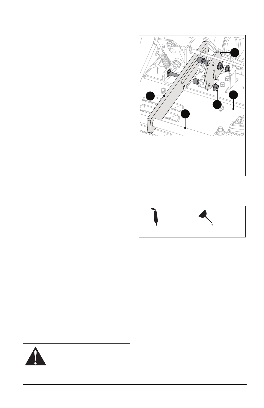
ADJUST TRACTION DRIVE
CLUTCH
See Figure 40.
1. Stop engine, remove key and wait for all
moving parts to stop and for hot parts to
cool.
2. Disconnect spark plug wire.
3. Loosen hardware securing belt cover to
unit and remove belt cover.
1
3
2
1. Idler
2. Belt
3. Pulley
Figure 37
Measure
here.
1. Brake Pad
2. Attachment Pulley
1
2
Figure 38
Measure here.
Figure 39
EN - 26
IMPORTANT: DO NOT completely remove
hardware from unit.
4. Loosen jam nut on traction cable
adjustment barrel, and then turn
adjustment barrel down to shorten cable
and remove cable slack.
5. With the traction clutch disengaged,
make sure auger idler arm lightly touches
the frame. See Figure 41.
6. Tighten jam nut on cable adjustment
barrel. See Figure 40.
7. Reinstall belt cover and tighten hardware.
8. Reconnect spark plug wire.
ADJUST HEIGHT-ADJUSTMENT
CABLE
Model 926091
See Figure 42.
IMPORTANT: Make sure height adjuster lock
finger is fully engaged before making
adjustments.
1. Loosen jam nuts on cable adjustment
barrel.
2. Tighten right jam nut to remove slack
between adjustment barrel and cable
eyelet.
3. Tighten left jam nut.
1. Traction Drive Clutch Cable
2. Cable Adjustment Barrel
3. Jam Nut
1
2
3
Figure 40
Figure 41
Check position
here.
1. Lock Finger
2. Jam Nut
3. Adjustment Barrel
4. Cable Eyelet
5. Cable Slack
2
1
5
4
3
Figure 42
EN - 27
See Controls & Features on page 8 for fuse
box location.
Replace Fuse
IMPORTANT: To avoid damaging the circuit,
replace fuses with fuses of the same
amperage (A) rating. Determine the cause of
electrical failure and repair before replacing
failed electrical components.
1. Press locking clip and pull fuse box down
from cover.
2. Remove defective fuse.
3. Determine cause of fuse failure and
repair condition.
4. Install new fuse.
5. Insert fuse box into cover and push up
until locking clip snaps into place.
Replace Relay
See Figures 43 and 44.
NOTICE: Relays are interchangeable. Use
only quality replacement parts. See Service
Parts on page 16.
1. Press locking clip and pull fuse box down
from cover.
2. Remove defective relay.
3. Determine cause of relay failure and
repair condition.
4. Install new relay.
5. Insert fuse box into cover and push up
until locking clip snaps into place.
09391400
Model 926081
09391600
Model 926091
ELECTRICAL SERVICE
7.555
Figure 43
1. System EFI Fuse 5A
2. Battery EFI Fuse 5A
3. Headlight / Heated Hand Grip
Fuse 7.5A
1
2
3
5
10
7.5
5
1. System EFI Fuse 5A
2. Lighting Fuse 7.5A
3. Battery EFI Fuse 5A
4. Discharge Chute Controls / Hand
Warmer Fuse 10A
5. Heated Hand Grip Cutout Relay
1
2
3
4
5
Figure 44

EN - 28
TROUBLESHOOTING
Problem Probable Cause Correction
Engine will not
start.
Engine is turned off. Turn engine key to run position. See
Engine Key on page 10.
Fuel tank is empty. Fill tank with fuel. See Before Operating
Unit on page 13. ECU will display a red
blink code. See Controls & Features on
page 8. Refer to the Service Manual for
your unit.
Ignition switch starter circuit is
not functioning. (Electric start)
See your dealer for repair.
Spark plug wire is disconnected. Connect spark plug. Refer to engine
manual.
Spark plug is faulty. Replace spark plug. Refer to engine
manual.
Engine is faulty. See your Ariens dealer or authorized
engine manufacturer’s service center.
Also, refer to your unit’s service manual.
Battery is discharged. See Charge Battery on page 20. See
Controls & Features on page 8. Refer to
the Service Manual for your unit.
EFI battery is disconnected. Connect EFI battery. See Start The
Engine on page 13.
Plugged inline fuel filter. Replace inline fuel filter. Refer to the
Service Manual for your unit.
Battery fuse blown. Fuses typically fail due to short circuit.
See dealer for repair.
Engine starts
hard or runs
poorly.
Plugged inline fuel filter. Replace inline fuel filter. Refer to the
Service Manual for your unit.
Spark plug is faulty, fouled or
incorrectly gapped.
Clean and correctly set spark plug gap
(refer to engine manual) or see your
Ariens dealer.
Fuel cap vent is blocked. Install new fuel cap.
Engine stops.
Fuel tank is empty. Fill tank with fuel. See Before Operating
Unit on page 13. ECU will display a red
blink code. See Controls & Features on
page 8. Refer to the Service Manual for
your unit.
Obstruction in auger or impeller. Stop engine, remove key and wait for all
moving parts to stop. Check for and
remove obstruction before restarting.
Contaminated fuel supply. Replace with clean fuel.
Engine is faulty. See your Ariens dealer or authorized
engine manufacturer’s service center.
Also, refer to your unit’s service manual.
Spark plug is faulty. Replace or clean spark plug. Refer to
engine manual.
Fuel cap vent is blocked. Install new fuel cap.
Battery is dead. See Charge Battery on page 20.
Plugged inline fuel filter. Replace inline fuel filter. Refer to the
Service Manual for your unit.

EN - 29
Unit runs
briefly then
stops.
A build up of fumes in the fuel
tank is creating too much
pressure in the fuel tank.
Slowly loosen the fuel tank cap.
Unit does not
drive forward
or in reverse.
Traction drive cable is not
adjusted correctly.
Remove slack from cable. See Adjust
Traction Drive Clutch on page 25.
Traction belt is not functioning. Repair or replace traction drive belt. Refer
to the service manual for your unit.
Speed selector is not adjusted
correctly.
Adjust speed selector. See Adjust Speed
Selector Lever on page 23.
Transmission is bypassed. Push the bypass rod in to engage the
transmission for normal operation. See
Move Unit Manually on page 15.
Unit does not
throw snow or
throws it
poorly.
Shear bolts are broken. See Replace Shear Bolts on page 21.
Attachment clutch / brake is not
adjusted correctly.
See Adjust Attachment Clutch & Brake on
page 23.
Impeller is frozen in place. Move unit to a warm place to thaw.
Ice or debris is obstructing auger. Stop engine, remove key and wait for
moving parts to stop. Check for and
remove obstruction before restarting.
Discharge chute is clogged with
snow.
Stop engine, remove key and wait for all
moving parts to stop and for hot parts to
cool. Clean discharge chute and auger
housing with clean-out tool. DO NOT use
your hands.
Auger drive belt is slipping, worn
or damaged.
Adjust or replace auger drive belt. Refer
to the service manual for your unit.
Auger drive belt is loose or
damaged.
Replace belt or adjust auger control
cable. Refer to the service manual for
your unit.
Throttle control knob is in wrong
position.
Ensure throttle control knob is set to high
position.
Excessive
snow is left
behind.
Scraper blade is worn or
damaged.
Adjust when worn and replace when
damaged or when blade has been
adjusted down as far as possible and
does not touch ground or clear correctly.
See Adjust Scraper Blade on page 21.
Unit pulls to
the left or right.
Skid shoes and scraper blade
need adjustment.
Adjust skid shoes and scraper blade. See
Adjust Skid Shoes and Adjust Scraper
Blade on page 21.
Belt squeals
continuously.
Impeller may be frozen. Move unit to a warm area to thaw.
Attachment clutch needs
adjustment.
See Adjust Attachment Clutch & Brake on
page 23.
Discharge
chute controls
do not work
(Model 926091).
System has self protected due to
over-heating.
DO NOT operate controls momentarily to
allow protection feature to cool.
Discharge
chute controls
do not work
after cooling
(Model 926091).
Fuse is blown. Check and replace fuse with fuse of
equivalent rating. If fuse is not blown or
continues to blow, refer to your Service
Manual.
Engine is not running. Start and run engine.
TROUBLESHOOTING
Problem Probable Cause Correction
EN - 30
SHORT TERM
1. Run auger / impeller for a few minutes to
remove loose or melting snow to prevent
impeller from freezing.
2. Tighten all hardware to correct
specifications.
3. Inspect unit for visible signs of wear or
damage. Repair as needed.
4. Apply a light layer of oil or anti-rust
compound on bare metal areas.
5. Prepare fuel system for storage.
NOTICE: Ariens recommends using a quality
fuel stabilizer in all fuel. For the best
effectiveness, add stabilizer to all fuel
containers whenever purchasing fuel. Add
the stabilizer to the container before adding
fuel.
a. Add Ariens fuel stabilizer (see Service
Parts on page 16) or equivalent
according to manufacturer's
instructions to the fuel tank and any
fuel containers with remaining fuel.
6. Turn engine key to stop position and
remove key.
7. Charge battery. See Charge Battery on
page 20.
8. Store unit in a cool, dry, protected area.
Do not store unit outdoors.
LONG TERM
1. Perform all short-term storage items.
2. Wash salt and other corrosive ice-melting
agent residue from unit with mild soap
and low-pressure water.
IMPORTANT: Never spray unit with high-
pressure water.
3. Lubricate as directed in Maintenance on
page 16.
4. Touch up all scratched painted surfaces.
5. Remove weight from wheels or tracks by
putting blocks under frame or axle.
6. Store unit in a cool, dry, protected area.
Do not store unit outdoors.
START-OF-SEASON FUEL
PREPARATION
Before starting unit for the first time after long-
term storage, add fresh, stabilizer-treated fuel
to the fuel tank and any fuel containers with
remaining fuel.
See your Ariens dealer for a complete list of
compatible accessories and attachments for
your unit.
STORAGE
WARNING: AVOID INJURY.
Read and understand the Safety
section before proceeding.
ACCESSORIES
Description Part No.
Front Weight Kit 72406500
16" x 8" Tire Chain Set (Model
926081)
72601800
Composite Skid Shoe Kit
(Set of 2)
72603100
Cover 72601500
Snow Cab 72103300
Protective Floor Mat 70706700
120V Extension Cord Kit 02483100

EN - 31
SPECIFICATIONS
Model Number 926081 926091
Description
Hydro Pro 36 EFI
Hydro Pro 28 EFI
RapidTrak
Engine Ariens AX420 EFI
Gross Torque* – N•m (lb-ft) 28.6 (21.0)
Displacement – cm
3
(in
3
)
420.0 (25.6)
Maximum RPM – No load 3600 ± 50
Electric Start 120V
Fuel Tank Capacity – liter (qt) 2.8 (3.0)
Headlight LED
Chute
Chute Rotation Angle 200°
Rotation Control Quick Turn Electric
Deflector Control In-Dash Lever Electric
Auger
Snow Clearing Width – cm (in) 91.4 (36.0) 71.1 (28.0)
Gearcase Cast Iron
Auger Diameter – cm (in) 40.6 (16.0)
Impeller
Impeller Diameter – cm (in) 35.6 (14.0)
Impeller Speed (RPM) 1059
Impeller Tip Speed – m/sec (ft/sec) 19.7 (64.6)
Drive
Auger Dual HA Belt
Traction Hydrostatic
Speeds Infinitely Variable
Axle Control Auto-Turn™
Tires
Size – in 16 x 6.5-8 N/A
Rubber Track Size – cm (in) N/A 14.0 (5.5) Track
Pressure See tire sidewall. N/A
Size and Weight
Length – cm (in) 153.2 (60.3) 153.9 (60.6)
Height – cm (in) 118.4 (46.6) 116.6 (45.9)
Width – cm (in) 97.0 (38.2) 76.7 (30.2)
Weight – kg (lb) 145.2 (320.0) 153.8 (339.0)
*Engine output stated in gross torque per SAE J1940 as rated by engine manufacturer.
4/22 • 05299800I
EN - 32
AriensCo warrants to the original purchaser that Ariens brand products purchased on or after 1/1/2022 will
be free from defects in material and workmanship for the time period noted in the chart below. Equipment put
to personal use around a single household or residence is considered “Residential Use.” Equipment put to
any business use (agricultural, commercial, or industrial) or used at multiple locations is considered
“Commercial Use.” If any product is rented or leased, then the duration of these warranties shall be 90 days
after the date of purchase.
An authorized Ariens dealer will repair any defect in material or workmanship, and repair or replace any
defective part, subject to the conditions, limitations and exclusions set forth herein. Such repair or
replacement will be free of charge (labor and parts) to the original purchaser; except as noted below. Pick-up
and delivery are at the owner’s expense.
The warranty code is found on the model and serial number identification label on the unit.
* Whichever comes first.
Special Extensions
The chart below details special extensions to warranty terms. Warranty terms are total time periods
covered. If any product is rented or leased, there are no extensions to the 90-day warranty.
Outdoor Power
Equipment
Limited Warranty
Warranty
Code
Product Group Warranty Period
AA Serialized Attachments 1 Year.
CH, CQ Zenith Mowers 4 Years or 750 Hours.*
HD LM-Series Walk-Behind Mowers 3 Years Residential Use. 90 Days Commercial Use.
HE Edge Mowers 2 Years or 150 Hours.*
HF Ikon-XD Mowers 3 Years or 300 Hours.*
HH Apex Mowers 4 Years or 500 Hours.*
PA 921-Series Brushes 3 Years Residential Use. 90 Days Commercial Use.
PB 926-Series Brushes 3 Years Residential Use. 1 Year Commercial Use.
SA Professional Sno-Thro 3 Years Residential Use. 1 Year Commercial Use.
SB
Compact, Deluxe and Platinum Sno-Thro
and Path-Pro
3 Years Residential Use. 90 Days Commercial Use.
SC S18 2 Years Residential Use. 90 Days Commercial Use.
SD Deluxe and Platinum EFI Sno-Thro 3 Years Residential Use. 90 Days Commercial Use.
SE 920-Series Classic Sno-Thro, Crossover 3 Years Residential Use. 90 Days Commercial Use.
SF Mammoth Tractor 2 Years or 500 Hours.*
Warranty
Code
Warranty Term Extension Warranty Period
SA Cast Iron Auger Gear Case 5 Years.
SB, SD Cast Iron Auger Gear Case
5 Years Residential Use.
1 Year Commercial Use.
Warran
ty

4/22 • 05299800I
EN - 33
Exclusions and Limitations
The charts below detail special exclusions and limitations to this warranty.
Exclusions – Items Not Covered by This Warranty
• Parts that are not genuine Ariens service parts are not covered by this warranty and may void the war-
ranty if the parts result in premature wear or damage to the product.
• Damages resulting from the installation or use of any part, accessory, or attachment which is not approved
by AriensCo for use with product(s) identified herein are not covered by this warranty.
• Any misuse, alteration, improper assembly, improper adjustment, neglect, or accident which requires
repair is not covered by this warranty.
• Repairs or adjustments required due to failure to use fresh fuel or failure to properly prepare the unit for
periods of non-use.
• Use of gasoline blends exceeding 10% ethanol voids any and all warranties.
• Any tampering with the hour meter voids any and all warranties.
• Products are designed to the specifications in the area that the product was originally distributed. Differ-
ent areas may have significantly different legal and design requirements. This warranty is limited to the
requirements in the area in which the unit was originally distributed. AriensCo does not warrant this prod-
uct to the requirements of any other area. Warranty service is limited to service within the area originally
distributed.
• In countries other than the United States and Canada, contact the AriensCo dealer for
warranty policies that govern within your country. Rights may vary from country to country and within any
one country.
Evaporative Emissions Control Warranty Exception
As required by the California Air Resources Board (CARB) and the US Environmental Protection Agency
(EPA) the evaporative emissions control system is warranted to the ultimate purchaser, and any subsequent
owner, for two years.
The CARB and EPA evaporative emissions control system warranty is described in a separate evaporative
emission control warranty statement.
Battery Warranty
Battery warranty is one year. Units used for rental or lease have no exceptions to the 90-day warranty. Total
battery claim reimbursement will not exceed 45.00 USD.
Warranty Term Exclusions Warranty Period
Air filters, auger paddles, brake arms, brake linings, brake shoes,
brushes, cutters, fuel filters, halogen headlights, knives, halogen light
bulbs, lubricants, mower blades, oil, oil filters, spark plugs, scraper
blades, shear bolts and skid shoes.
Components are not covered
under warranty.
Hydro-Gear Transaxle Limitation
See Hydro-Gear warranty. The warranty is administrated by AriensCo. Refer to www.ariens.com for
warranty statement.
Warranty Term Limitations Warranty Period
Cloth, Plastic and Rubber Components.
Mufflers, Tires and Belts.
Components are covered for manufacturer’s defect only, not
wear.
Parker Actuators 1 Year.

4/22 • 05299800I
EN - 34
Engines
The chart below details engine warranty information. Engine warranty terms may vary from the specific terms
of this warranty. If inconsistent, the terms of the engine warranty shall apply to the engine and its component
parts.
Parts and Accessories
Service replacement parts and non-serialized accessories are warranted for 90 days from date of purchase.
Labor is not included.
Customer Responsibilities
Register the product immediately at the time of sale. If the dealer does not register the product, the
customer must register the unit on-line at www.ariens.com.
To obtain warranty service, the original purchaser must:
• Ensure that the maintenance and adjustments explained in the Operator’s Manual are routinely
completed.
• Promptly notify AriensCo or an authorized Ariens service representative of the need for warranty service.
• Transport the product to and from the place of warranty service at owner’s expense.
• Have the warranty service performed by an authorized Ariens service representative.
To find an authorized dealer use the dealer locator on our websites, or contact us by mail or phone.
Engine Manufacturer Detail
Ariens AX
Ariens-branded engines are warranted by the manufacturer
and the warranty is administrated by AriensCo. Refer to the
engine manual or www.ariens.com for warranty statements.
Briggs & Stratton, Kawasaki, Kohler
Covered by the engine manufacturer’s warranty.
Refer to the engine manufacturer’s warranty statements.
Globally (Except Australia or
New Zealand):
Australia: New Zealand:
AriensCo
655 W. Ryan Street
Brillion, WI 54110
Phone: (920) 756 - 4688
www.ariensco.com
Masport Australia Pty Ltd
27 Commercial Drive
Dandenong South
Victoria 3175
Australia
Phone: 1300 366 225
www.masport.com.au
Masport Ltd
320 Ti Rakau Drive
East Tamaki
Auckland 2013
New Zealand
Phone: 0800 627 7678
www.masport.co.nz

4/22 • 05299800I
EN - 35
Disclaimer
AriensCo may from time to time change the design of its products. Nothing contained in this warranty shall be
construed as obligating the AriensCo to incorporate such design changes into previously manufactured
products, nor shall such changes be construed as an admission that previous designs were defective.
Limitation of Remedy and Damages
AriensCo liability under this warranty, and under any implied warranty that may exist, is limited to repair of
any defect in workmanship, and repair or replacement of any defective part. AriensCo shall not be liable for
incidental, special, or consequential damages (including lost profits). Some states do not allow the exclusion
of incidental or consequential damages, so the above limitation or exclusion may not apply to you.
AriensCo shall not be held liable for damages, including premature wear and tear, or injuries caused by
installation of unauthorized parts and accessories or for parts and accessories not installed by an authorized
Ariens dealer.
Australian Consumer Law
The following applies solely to warranties subject to Subsection 102(1) of the Australian Consumer Law: Our
goods come with guarantees that cannot be excluded by the Australian Consumer Law. You are entitled to a
replacement or refund for a major failure and for compensation for any other reasonably foreseeable loss or
damage. You are also entitled to have the goods repaired or replaced if the goods fail to be of acceptable
quality and failure does not amount to a major failure.
Disclaimer of Further Warranty
AriensCo makes no warranty, express or implied, other than what is expressly made in this warranty. If the
law of your state provides that an implied warranty of merchantability, or an implied warranty of fitness for
particular purpose, or any other implied warranty, applies to AriensCo, then any such implied warranty is
limited to the duration of this warranty. Some states do not allow limitations on how long an implied warranty
lasts, so the above limitation may not apply to you.
This warranty gives you specific legal rights, and you may also have other rights which vary from region to
region.

655 West Ryan Street
Brillion, WI 54110
www.ariens.com
parts.ariens.com
P
R
I
N
T
E
D