
CANDY HOOVER GROUP S.R.L. • Via Comolli 16 • 20861 Brugherio (MB) Italy
TOUCH CONTROL VITROCERAMIC COOKING HOBS
INSTALLATION ADVICES - INSTRUCTIONS FOR THE USE
GB
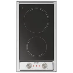
• CH95CE

22
33
Dear Customer,
Thank you for having purchased and given your preference
to our product.
The safety precautions and recommendations reported
below are for your own safety and that of others. They
will also provide a means by which to make full use of the
features oered by your appliance.
Please preserve this booklet carefully. It may be useful
in future, either to yourself or to others in the event that
doubts should arise relating to its operation.
This appliance must be used only for the task it
has explicitly been designed for, that is for cooking
foodstus. Any other form of usage is to be considered
as inappropriate and therefore dangerous.
The manufacturer declines all responsibility in the
event of damage caused by improper, incorrect or
illogical use of the appliance.
IMPORTANT INFORMATION FOR CORRECT DISPOSAL OF THE PRODUCT IN
ACCORDANCE WITH EC DIRECTIVE 2012/19/EC.
At the end of its working life, the product must not be disposed of as
urban waste. It must be taken to a special local authority dierentiated
waste collection centre or to a dealer providing this service.
Disposing of a household appliance separately avoids possible negative
consequences for the environment and health deriving from inappropriate
disposal and enables the constituent materials to be recovered to obtain
signicant savings in energy and resources. As a reminder of the need
to dispose of household appliances separately, the product is marked
with a crossed-out wheeled dustbin.
DECLARATION OF CE CONFORMITY
• This appliance has been designed to be used only for cooking. Any other use (such as
heating a room) is improper and dangerous.
• This appliance has been designed, constructed, and marketed in compliance with:
- Safety requirements of the “Low voltage” Directive 2014/35/EU;
- Safety requirements of the “EMC” Directive 2014/30/EU;
- Requirements of EU Directive 93/68/EEC;
- Requirements of EU Directive 2011/65/EU.

44
IMPORTANT SAFETY PRECAUTIONS AND RECOMMENDATIONS
IMPORTANT: This appliance is designed and manufactured
solely for the cooking of domestic (household) food and is
not suitable for any non domestic application and therefore
should not be used in a commercial environment.
The appliance guarantee will be void if the appliance is used
within a non domestic environment i.e. a semi commercial,
commercial or communal environment.
Read the instructions carefully before installing and using
the appliance.
• This appliance has been designed and manufactured in
compliance with the applicable standards for the household
cooking products and it fullls all the safety requirements shown
in this manual, including those for surface temperatures.
Some people with sensitive skin may have a more pronounced
temperature perception with some components although these
parts are within the limits allowed by the norms.
The complete safety of the appliance also depends on the correct
use, we therefore recommend to always pay a extreme attention
while using the product, especially in the presence of children.
• After having unpacked the appliance, check to ensure that it is
not damaged.
In case of doubt, do not use it and consult your supplier or a
professionally qualied technician.
• Packing elements (i.e. plastic bags, polystyrene foam, nails,
packing straps, etc.) should not be left around within easy reach
of children, as these may cause serious injuries.
• Some appliances are supplied with a protective lm on steel and
aluminium parts. This lm must be removed before using the
appliance.
• IMPORTANT: The use of suitable protective clothing/gloves is
recommended when handling or cleaning this appliance.
• Do not attempt to modify the technical characteristics of
the appliance as this may become dangerous to use. The
manufacturer declines all responsibility for any inconvenience
resulting from the inobservance of this condition.

55
• Do not operate your appliance by means of an external timer or
separate remote-control system.
• Do not carry out cleaning or maintenance operations on the
appliance without having previously disconnected it from the
electric power supply.
• Do not use a steam cleaner because the moisture can get into
the appliance therefore making it unsafe.
• Do not cover the hob with aluminium foils.
• Do not touch the appliance with wet or damp hands (or feet).
• Do not use the appliance whilst in bare feet.
• If you should decide not to use this appliance any longer (or
decide to substitute another model), before disposing of it, it
is recommended that it be made inoperative in an appropriate
manner in accordance to health and environmental protection
regulations, ensuring in particular that all potentially hazardous
parts be made harmless, especially in relation to children who
could play with unused appliances.
• The various components of the appliance are recyclable. Dispose
of them in accordance with the regulations in force in your country.
If the appliance is to be scrapped, remove the power cord.
• After use, ensure that the controls are in the o position.
• Children less than 8 years of age shall be kept away unless
continuously supervised.
• This appliance can be used by children aged from 8 years and
above and persons with reduced physical, sensory or mental
capabilities or lack of experience and knowledge if they have
been given supervision or instruction concerning use of the
appliance in a safe way and understand the hazards involved.
Children shall not play with the appliance. Cleaning and user
maintenance shall not be made by children without supervision.
• The manufacturer declines all liability for injury to persons or
damage to property caused by incorrect or improper use of the
appliance.

66
• WARNING: During use the appliance and its accessible parts
become hot; they remain hot for some time after use.
– Care should be taken to avoid touching heating elements on
the hob.
– To avoid burns and scalds, young children should be kept
away.
• Make sure that electrical cables connecting other appliances in
the proximity of the cooktop cannot come into contact with the
hob.
• WARNING: Unattended cooking on a hob with fat or oil can be
dangerous and may result in re. NEVER try to extinguish a re
with water, but switch o the appliance and then cover ame e.g.
with a lid or a re blanket.
• WARNING: Danger of re: do not store items on the cooking
surfaces.
• Do not place or leave empty pans on the glass ceramic hob.
• Do not allow heavy or sharp objects to drop on the glass ceramic
hob.
• Do not scratch the hob with sharp objects. Don’t use the hob as
a work surface.
• WARNING: If the hob is cracked or otherwise damaged by falling
objects etc., disconnect the appliance from the electrical power
supply to avoid the possibility of electric shock and call Customer
Service.
• WARNING: When correctly installed, your product meets all
safety requirements laid down for this type of product category.
However special care should be taken around the underneath
of the appliance as this area is not designed or intended to be
touched and may contain sharp or rough edges, that may cause
injury.
• CAUTION: The cooking process has to be supervised. A short
term cooking process has to be supervised continuously.
• Models provided with power supply cable. If the power supply
cable is damaged, it must be replaced only by an authorised
service agent in order to avoid a hazard.

77
• If the appliance is not tted with a supply cord and a plug, or with
other means for disconnection from the supply mains having a
contact separation in all poles that provide full disconnection under
overvoltage category III conditions, means for disconnection
must be incorporated in the xed wiring in accordance with the
wiring rules.
• WARNING: The appliance and its accessible parts become hot
during use.
Care should be taken to avoid touching heating elements.
Children less than 8 years of age shall be kept away unless
continuously supervised.
• WARNING: Use only hob guards designed by the manufacturer
of the cooking appliance or indicated by the manufacturer of the
appliance in the instructions for use as suitable or hob guards
incorporated in the appliance. The use of inappropriate guards
can cause accidents.

88
ENERGY LABELLING/ECODESIGN
• Commission regulation (EU) No 66/2014 (implementing Directive 2009/125/EC of the
European Parliament and of the Council).
Reference to the measurement and calculation methods used to establish compliance with
the above requirements:
• Standard EN 60350-2 (hobs: electric cooking zones and/or areas).
USE OF THE APPLIANCE, ENERGY SAVING TIPS
HOB
ELECTRIC COOKING ZONES AND/OR AREAS
• Avoid pouring liquids on the zones/areas while they are hot.
• Use at-bottomed (electric hotplate type) pots and pans only.
• Use cooking receptacles which cover as much of the surface of the cooking zone/area
as possible.
• To save electricity, use lids whenever possible.
• When the pan comes to the boil, turn the heat down to the level desired. Remember
that the cooking zone/area will continue to produce heat for about ve minutes after it
has been turned o.

99
Advice for
the installer

1010
IMPORTANT:
• The appliance is designed and approved for domestic use only and should not be
installed in a commercial, semi commercial or communal environment.
Your product will not be guaranteed if installed in any of the above environments
and could aect any third party or public liability insurances you may have.
• This appliance is to be installed only by an authorised person according to the current
local regulations and in observation of the manufacturer’s instructions.
Failure to comply with this condition will render the guarantee invalid.
• Incorrect installation, for which the manufacturer accepts no responsibility, may cause
personal injury of damage.
• This appliance shall only be serviced by authorized personnel.
• Always disconnect the cooktop from mains power supply before carrying out any
maintenance operations or repairs.
• Important: The use of suitable protective clothing/gloves is recommended when
handling or installing this appliance.
• The appliance must be housed in heat resistant units.
• The walls of the units must not be higher than work top and must be capable of
resisting temperatures of 70 °C above room temperature.
• We would point out that the adhesive which bonds the plastic laminate to the
furniture must withstand temperatures not less than 150 °C to avoid delamination.
• Do not install the appliance near inammable materials (eg. curtains).
WARNING
When correctly installed, your product meets all safety requirements laid down for
this type of product category.
However special care should be taken around the underneath of the appliance as
this area is not designed or intended to be touched and may contain sharp or rough
edges, that may cause injury.
INSTALLATION
1
1111
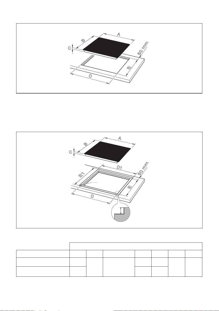
FLUSH INSTALLATION (MODELS WITHOUT METAL TRIM/S ONLY)
If you wish to install the hob ush with the work surface, it is neccessary to execute/carry
out a miling in the hole of the cut-out as indicated in g. 1.1b.
E
50 mm
D
A
B
C
Fig. 1.1a
E
50 mm
D
D1
E1
R7
5
A
B
C
Fig. 1.1b
STANDARD INSTALLATION
Measures (mm)
Description A (*) B (*) C (**) D D1 E E1
80cm wide models 780
520
50 or 55 for
ush
installation
740 785
480 525
90cm wide models 900 840 905
(*) For models with metal trim/s add 4mm to the measurement for each trim.
Example: front metal trim= B+4mm.
(**) from the top of countertop to bottom of cooktop.
1212
FITTING REQUIREMENTS
This cooktop can be built into a working surface from 20 mm thick and 600 mm deep.
In order to install the ceramic hob into the kitchen xture, a hole with the dimensions shown
in gures 1.1a and 1.1b has to be made, keeping in consideration the following:
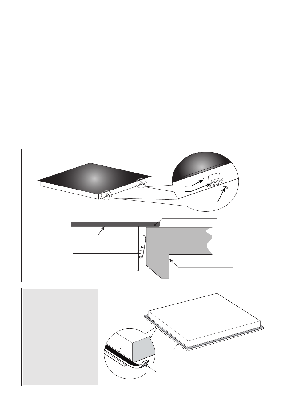
• A 20 mm ventilation gap must be provided between the bottom of the appliance and any
cabinetry, draw unit or oven (g. 1.3).
• If the cooktop is installed above an oven, the oven shall be provided with cooling fan.
The two appliances should be connected to the electrical supply with independent
connections.
• The ceramic hob must be kept no less than 50 mm away from any side wall
(from side
edge of cutout).
• The rear wall must be at least 50 mm from the ceramic hob
(from rear edge of cutout).
• There must be a distance of at least 650 mm between the hob and any wall cupboard
or extractor hood positioned immediately above (see g. 1.2).
• Standard installation (not ush): Do not seal the cooktop into the benchtop with silicone
or glue; this makes future servicing dicult. The manufacturer will not cover the costs
of removing the cooktop, or of damage caused by this removal.
• The walls surrounding the cooktop must be made of heat-resistant material.
• Do not install the appliance near inammable materials (eg. curtains).
min
20 mm
Fig. 1.3
650 mm
500 mm
450 mm
Fig. 1.2
50 mm minimum
between the side of the
cut-out and the side wall
1313
FASTENING THE COOKTOP
Each cooktop is provided with an installation kit including brackets and screws for fastening
the cooktop to benches from 20 mm thick. Before you install the cooktop, make sure that
the work surface is square and level, and no structural members interfere with space
requirements previously indicated.
The kit includes four metal clips “B” and four self-threading screws “A” (g. 1.4).
• Cut the unit according to the dimensions in g. 1.1a or 1.1b.
• Turn the hob upside down and rest the glass side on a soft surface.
• Spread the seal “D” around the edge of the hob (g. 1.5).
• Fasten the metal clips “B” into the hole “C” using the screws A”. Make sure that the
metal clips are mounted correctly as shown in the gure 1.4.
• Put the cooktop into the cutout and position it correctly.
• Using a sharp cutter or trimmer knife, trim the excess sealing material around the edge
of the cooktop. Take care not to damage the workbench.
• In case to install the hob ush with the work surface, ll any gaps between the glass
and along the perimeter of the work surface with insulating silicone, and wipe away
any excess.
D
D
Adhesive side
Adhesive side
Fig. 1.5
C
B
A
B
A
Fig. 1.4
Glass
Metal clips
Fixing screw
Worktop / kitchen cabinet
Seal “D”
IMPORTANT: Spread
the sealing material “D”
around the edge of the
hob (edge of the glass).
The sealing material
“D” must be installed
correctly to guarantee a
perfect seal between the
appliance and the unit.
Incorrect installation may
cause irreparable damage
to the appliance.

1414
ELECTRICAL SECTION
2
IMPORTANT: Installation must be carried out according to the manufacturer’s
instructions. Incorrect installation may cause harm and damage to people,
animals or property, for which the manufacturer accepts no responsibility.
Before carrying out any work on the electrical section of the appliance, it must be
disconnected from the mains.
Connection to a good earth wiring system is absolutely essential.
The manufacturer accepts no responsibility for any inconvenience caused by
failure to comply with this rule.
If the hob surface is cracked disconnect the appliance from the mains and contact
the After-Sales Service.
ELECTRICAL REQUIREMENTS
• Connection to the electric power supply must be carried out by a qualied technician
and following the appropriate safety regulations.
• The appliance must be connected to the mains checking that the voltage corresponds
to the value given in the rating plate and that the electrical cable sections can withstand
the load specied on the plate.
• The appliance should be connected directly to the mains placing an omnipolar switch
with minimum opening between the contacts of 3 mm between the appliance and the
mains.
• The power supply cable must not touch the hot parts and must be positioned so that it
does not exceed 50°C above ambient.
• Once the appliance has been installed, the switch must always be in a accessible
position.
• If the power supply cable is damaged it must be substituted by a suitable cable
available in the after sales service.
N.B. For connections to the mains power supply, never use adaptors, reductions or
multiple power points as these may overheat and catch re.
In the event that installation should require modications to the mains supply wiring system,
it is recommended that a qualied technician be called to carry out substitution.
He should also check that the domestic electrical system is suitable for the power absorbed
by the appliance.

1515
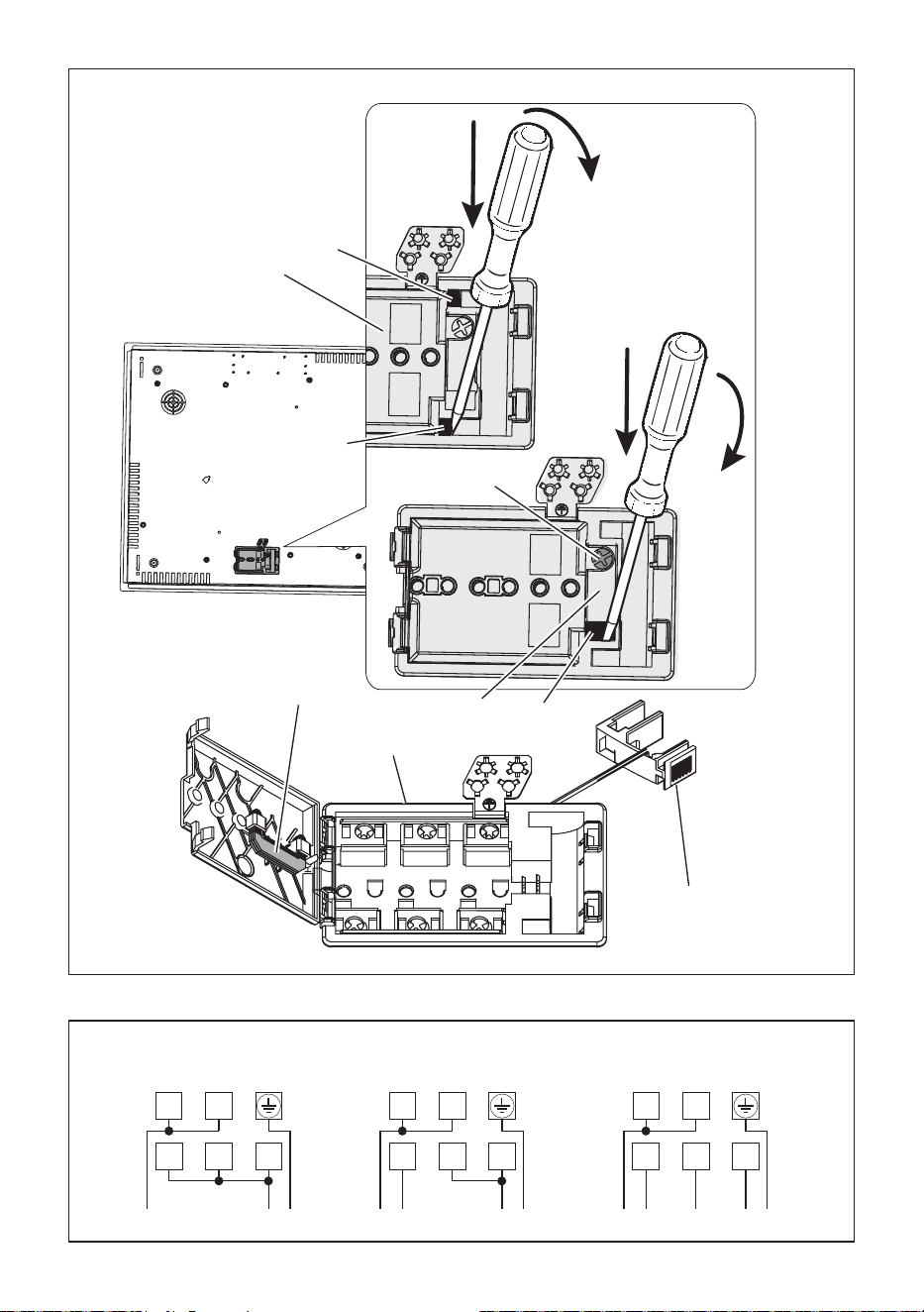
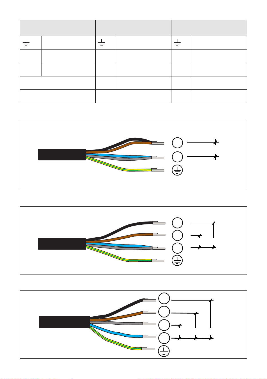
CONNECTION OF THE POWER SUPPLY CABLE
Important! This cooktop must be connected to the electricity supply only by an
authorised person.
To connect the feeder cable to the hob it is necessary to carry out the following operations:
• Unhook the terminal board cover “A” by inserting a screwdriver into the two hooks “B”
(g. 2.1). Open completely the terminal block cover “A”.
• Unscrew the screw “C”, then unhook the cable clamp “D” by inserting a screwdriver
into the hook “E”. Remove completely the cable clamp “D” (g. 2.1).
• Connect the phase, neutral and earth wires to terminal board “F” according to the
diagrams in g. 2.2; the U bolts “G” (g. 2.1) shall be used as indicated in the diagrams
in g. 2.2 (they are supplied already tted to the terminals or inside the terminal board,
behind the cover).
• Strain the feeder cable and block it with cable clamp “D” (by hooking hook “E” and
screwing screw “C”).
• Close the cover “A” of the terminal board “F” (check the two hooks “B” are correctly hooked).
NOTE: The earth conductor must be left about 3 cm longer than the others.
The operations must be executed by a qualied technician.
FEEDER CABLE SECTION “Type H05RR-F, H07RN-F or H05V2V2-F
(resistance to temperatures of 90°C)”
For 80 cm models:
220-240 V ac (V 2 ac) 3 x 2,5 mm
2
(*) (**) or 3 x 4 mm
2
(*) or 5 x 1,5 mm
2
(*)
380-415 V 2N ac 5 x 1,5 mm
2
(*) (***), some models only
380-415 V 3N ac 5 x 1,5 mm
2
(*) (***), some models only
For 90 cm models:
220-240 V ac (V 2 ac) 3 x 2,5 mm
2
(*) (**) or 3 x 4 mm
2
(*) or 3 x 6 mm
2
(*) or 5 x 2,5 mm
2
(*)
380-415 V 2N ac 5 x 2,5 mm
2
(*) (***), some models only
380-415 V 3N ac 5 x 2,5 mm
2
(*) (***), some models only
(*) Connection with wall box connection.
(**) Diversity factor applied. A diversity factor may be applied to the total loading of the
appliance only by a suitably qualied person.
(***) See also “MODELS SUPPLIED WITH POWER CORD 5x1,5 mm
2
OR 5x2,5 mm
2
ALREADY FITTED TO THE APPLIANCE”
MODELS SUPPLIED WITHOUT POWER CORD
ALREADY FITTED TO THE APPLIANCE
MODELS SUPPLIED WITH POWER CORD
ALREADY FITTED TO THE APPLIANCE
FEEDER CABLE SECTION “Type H05RR-F or “H05V2V2-F (resistance to
temperatures of 90°C)”
220-240 V ac (V 2 ac) 3 x 2,5 mm
2
(*) (**)
380-415 V 2N ac 4 x 2,5 mm
2
(*) for 90 cm models, or 4 x 1,5 mm
2
(*) for 80 cm models
380-415 V 3N ac 5 x 1,5 mm
2
(*)
(*) Connection with wall box connection.
(**) Diversity factor applied. A diversity factor may be applied to the total loading of the
appliance only by a suitably qualied person.
1616
1
2
1
2
A
B
B
E
F
G
C
D
D
Fig. 2.1
220 - 240 V~
L
1N (L2) PE
4
2
5
1
3
380 - 415 V 2N~
L
1N PE
4
2
5
1
3
L2
380 - 415 V 3N~
L
3N PE
4
2
5
1
3
L1 L2
Fig. 2.2
220 - 240 V ac (V 2 ac) 380 - 415 V 2N ac 380 - 415 V 3N ac

1717
• The cooktop is supplied with a power cord already tted to the appliance and it is
suitable for a single-phase type electrical connection (g. 2.3).
• For the two-phase type electrical connection (g. 2.4):
– separate the black and brown wires by removing the metallic terminal;
– remove about 5 mm of the insulation sheathing from the terminal end of the black
and brown wires;
– tightly t a new metallic terminal (1,5 mm or 2,5 mm, depending on wire size) on the
terminal end of each wire (black and brown).
• For the three-phase type electrical connection (g. 2.5):
– disconnect the blue and gray crimped wires from the terminal block and separate
them by removing the metallic terminal on both ends (to access the terminal block
see chapter “CONNECTION OF THE POWER SUPPLY CABLE”). Remove about
5 mm of the insulation sheathing from both the terminal ends of the blue and gray
wires. Tightly t a new metallic terminal (1,5 mm or 2,5 mm, depending on wire
size) on both the terminal ends of each wire (blue and gray). Connect the blue and
gray wires respectively to the N and L3 terminals of the terminal block and close
its cover.
– separate the black and brown wires by removing the metallic terminal. Remove
about 5 mm of the insulation sheathing from the terminal ends of the black and
brown wires. Tightly t a new metallic terminal (1,5 mm or 2,5 mm, depending on
wire size) on the terminal end of each wire (black and brown).
MODELS SUPPLIED WITH POWER CORD 5x1,5 mm
2
OR 5x2,5 mm
2
ALREADY FITTED TO THE APPLIANCE
ATTENTION!
All the operations/electrical connections must be carried out by a qualied technician.
CAUTION!
Do not pierce or weld the terminal ends of the wires. This is strictly forbidden!
CAUTION!
Do not connect the power cord to the electrical power supply without the metallic terminals
correctly in place.
If the supply cord is damaged, it must be replaced by the manufacturer or its service
agent or a similarly qualied person in order to avoid a hazard.
1818
“220-240 V ac (V 2 ac)”
connection
“380-415 V 2N ac”
connection
“380-415 V 3N ac”
connection
Green - Yellow Green - Yellow Green - Yellow
N
Blue and Gray
N
Blue and Gray
N
Blue
L
Black and Brown
L1
Black
L1
Black
/
L2
Brown
L2
Brown
/ /
L3
Gray
L
N
L1
N
L2
220...240 V ac
220...240 V ac
220-240 V ac
380-415 V 2N ac
L
N
L1
N
L2
220...240 V ac
220...240 V ac
220-240 V ac
380-415 V 2N ac
Fig. 2.3
Fig. 2.4
L
N
L1
N
L2
220...240 V ac
220...240 V ac
220-240 V ac
380-415 V 2N ac
L1
L3
L2
380-415 V 3N ac
N
220...240 V ac
Fig. 2.5
380-415 V 3N ac
380-415 V 2N ac
220-240 V ac (V 2 ac)

1919

2020
User guide
2121
Attention:
Detach the appliance from the mains if the ceramic glass is cracked and contact the After-
Sales Service.
Metallic objects such as knives, forks, spoons and lids should not be placed on the hob
surface since they can get hot.
Electrical insulation Class I
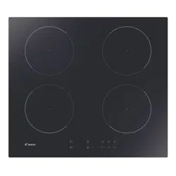
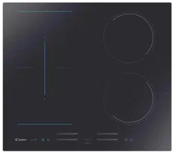
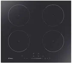
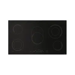
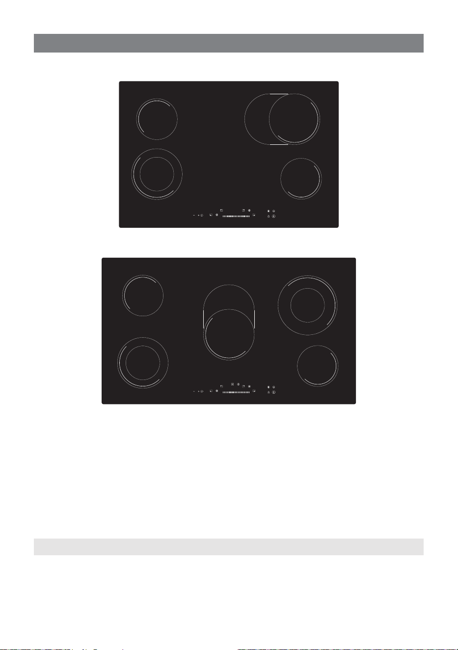
VITROCERAMIC COOKING HOB
1. “Hi-Light” single zone Ø 145 mm 1200 W
2. “Hi-Light” double zone (oval) Ø 180 x 260 mm 2200/1400 W
3. “Hi-Light” double zone Ø 180/120 mm 1700/700 W
4. “Hi-Light” double zone Ø 210/120 mm 2200/750 W
5. Touch controls
Fig. 1.1
FEATURES AND TECHNICAL DATA
1
3
1
4
2
1
5
3
1
1
2
5
Fig. 1.2
80cm wide models
90cm wide models
NOTE: This gures are indicative only. Symbols may vary.
2222
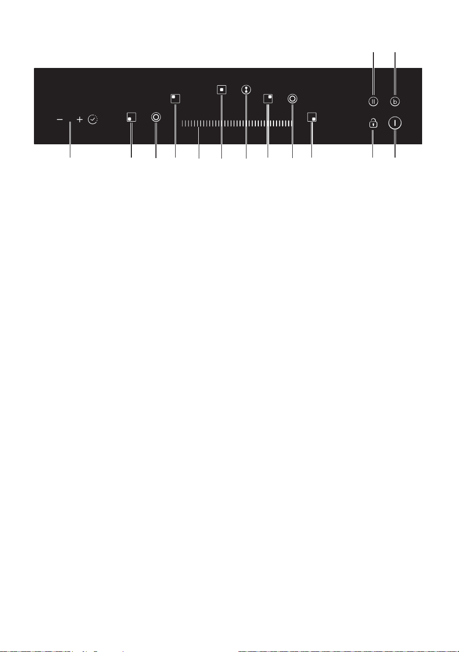
TOUCH-CONTROL DESCRIPTION
1. Front left cooking zone key
2. Front left double zone function key
3. Rear left cooking zone key
4. Central cooking zone key (only for model in g. 1.2)
5. Central double zone function key (only for model in g. 1.2)
6. Rear right cooking zone key
7. Rear right double zone function key
8. Front right cooking zone key
9. Setting selector
10. Automatic cooking timer key
11. ON/OFF key
12. Child lock selection key
13. Pause function key
14. Booster function key
Notes:
• Each selection (by touching one of the keys) is indicated by an acoustic signal (beep).
• The touch control area is switched o automatically (and a warning beep sounds for
10 seconds):
– if one or more keys are touched for more than 10 seconds;
– if an object is positioned on the touch control area;
– in the case of spillage of liquids on the control keys.
Attention: Detach the appliance from the mains if the ceramic glass is cracked and
contact the After-Sales Service. Metallic objects such as knives, forks, spoons and
lids should not be placed on the hob surface since they can get hot.
13
8 111210
7
5 63
2
41
14
9
Fig. 1.3
2323
The ceramic surface of the hob allows a fast transmission of heat in the vertical direction,
from the heating elements underneath the ceramic glass to the pans set on it.
The heat does not spread in a horizontal direction, so that the glass stays “cool” at only a
few centimeters from the cooking plate.
The cooking zones are shown by painted disks on the ceramic surface.
Before switching on the cooktop make sure that it is clean.
Important note:
The heating elements incorporate a thermolimiter that switches the element ON/OFF
during all settings to protect the ceramic glass from overheating.
The use of incorrect pans and/or wrong pan positioning will cause the temperature limiter
to operate more frequently, resulting in a reduction of cooking performance.
The temperature limiter can be seen under the glass dissecting the element. This is not a
fault with the appliance.
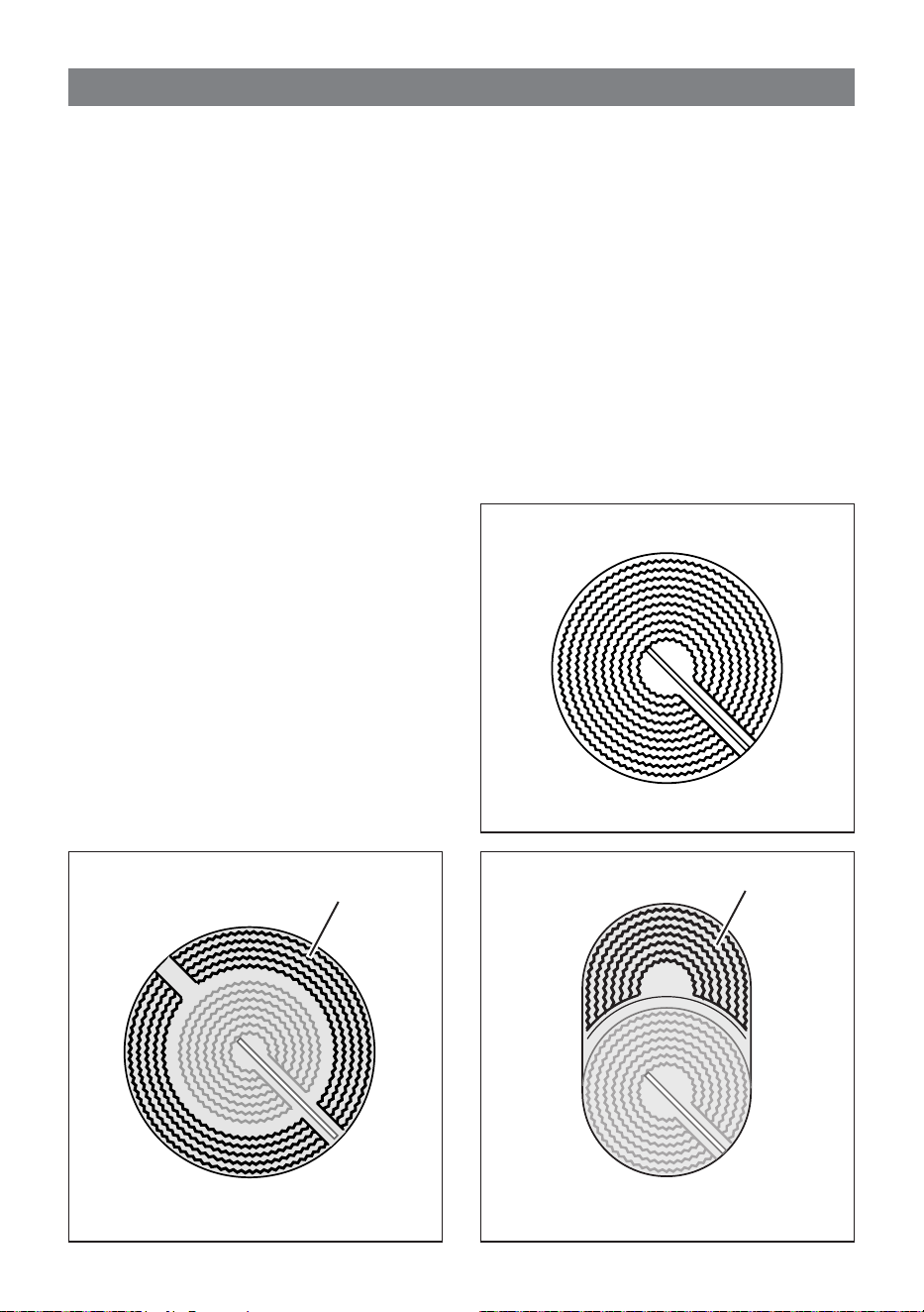
HI-LIGHT RADIANT ZONES (g. 2.1)
The heating element is formed of a coil of
resistant material which reaches the working
temperature quickly.
HI-LIGHT DOUBLE ZONE and HI-
LIGHT OVAL ZONE (g. 2.2, 2.3)
The heating element is formed of a 2 coils of
resistant material which reaches the working
temperature quickly (see pag. 26).
Fig. 2.1
DOUBLE ZONE
DOUBLE ZONE (OVAL)
Second element
Second element
Fig. 2.2 Fig. 2.3
HOW TO USE THE TOUCH CONTROL
2
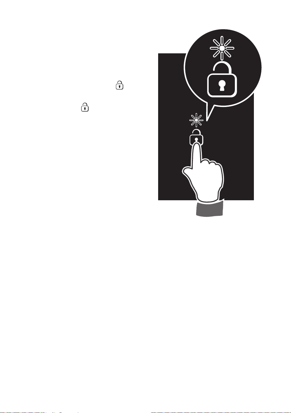
2424
Fig. 2.4
Notes:
• Each selection (by pressing one of the
keys) is indicated by an acoustic signal
(beep).
Any time the cooktop is connected to
the electrical supply or after a power
failure, the safety key-lock protection
will be automatically activated
(indicator light ON above key
).
• Before starting to use the cooktop
deactivate the key-lock protection by
pressing the key
.
This operation is necessary for the
keyboard calibration, to adapt the
sensibility of the keys (do not use
gloves, use a clear nger).
• If an object is positioned on the touch
control area, or in the case of spillage
of liquids on control keys, the touch
control is switched o automatically
10 seconds after having detected the
object/liquid.
• When the touch control reaches an
ambient temperature above 96°C,
one heating element is switched o.
This element cannot be used until the
temperature falls below 89°C.
2525
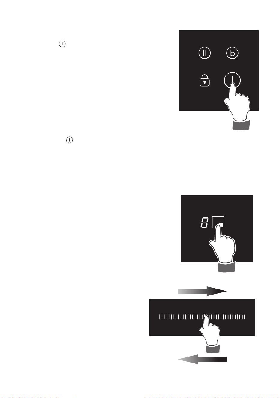
HOW TO SWITCH ON/OFF THE COOKTOP
Switching ON
Touch the key
until the touch control system is lit (g.
2.5). The displays of the cooking zones read “ 0 ”.
Notes:
• If the safety key-lock protection is active, the
touch control can be turned ON only after having
deactivated this protection.
• Auto switch-o: If a cooking zone is not turned
ON within 10 seconds, the touch control will
automatically switch o.
Switching OFF
The cooktop may be switched Off at any time by
pressing the key
.
If any cooking zones are turned On, they will be turned
Off.
POWER IGNITION AND ADJUSTMENT OF A
COOKING ZONE
To turn On a cooking zone the cooktop must be
switched On (see section “HOW TO SWITCH ON/OFF
THE COOKTOP”).
• Select a cooking zone by touching the relevant
display of the cooking zone to be used (g. 2.6).
• Select a setting on the selector [between “ 1 ”
(minimum) and “ 9 ” (maximum)]: touch at one point
to “jump” to a specic setting or slide your nger
along the selector (g. 2.7).
• The cooking zone display shows the
selected level.
• The power level can be modied at any
time.
Increase
Decrease
Fig. 2.5
Fig. 2.6
Fig. 2.7
2626
FUNCTIONING OF THE DOUBLE COOKING
ZONE
The double cooking zone consists of two circuits, which
may be used in the following modes:
• Reduced cooking zone: only the rst heating unit
is switched ON.
• Extended cooking zone: the rst and second
heating circuits are both switched ON.
Turn on the cooking zone as described in the section:
“POWER IGNITION AND ADJUSTMENT OF A
COOKING ZONE”; only the rst heating unit will switch
on.
Press the key
to operate also the second heating
circuit (the indicator light close to the display of the
cooking zone will light up), then set the desired power
level.
To turn o the second heating circuit press the key
(the indicator light close to the
display of the cooking zone will go out).
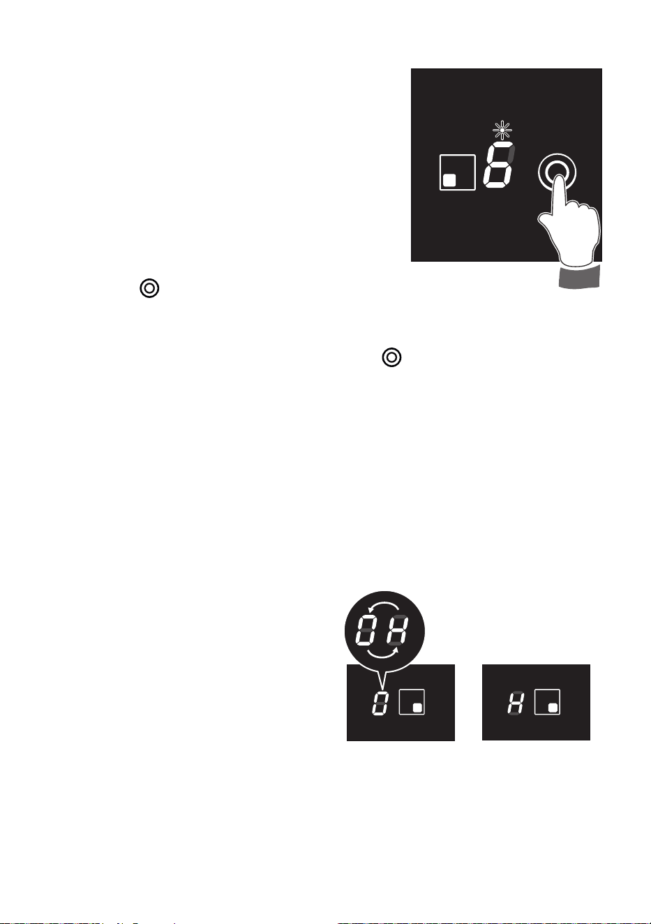
AFTERHEAT IN COOKING ZONE/S
When switching o a cooking zone (power
level “ 0 ”), if the temperature of the zone is
too warm to be touched the display will show
alternately “ H ” and “ 0 ”.
Whenever the touch control is switched o,
the residual heat is shown by a static “ H ”.
“ H ” is turned OFF when the cooking zone
temperature drops below 65 °C.
Fig. 2.8
Fig. 2.9
2727
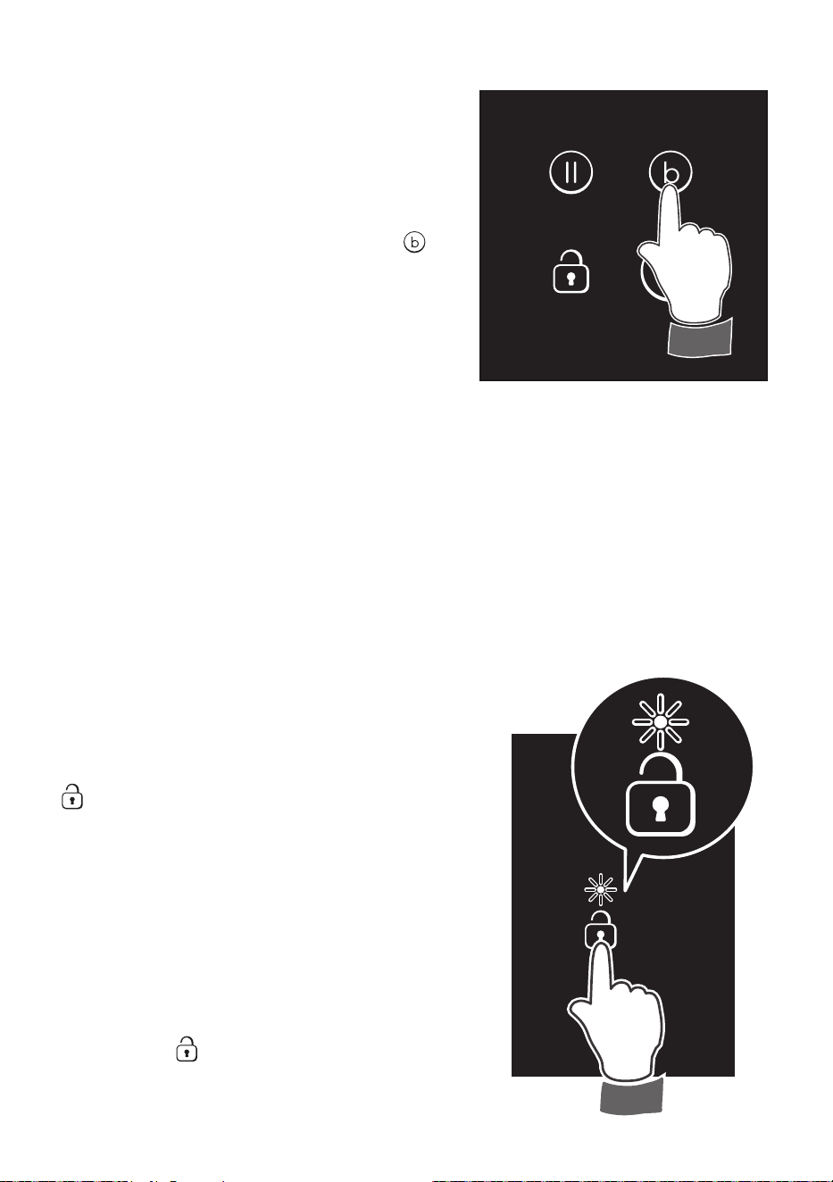
SAFETY KEY-LOCK TO PROTECT
CHILDREN
This function locks the touch-control keys
against unwanted activation.
To activate the key-lock press the key
; the indicator light close to the lock
symbol will light up.
• Cooking zone/s operating (power
level already set) - with the key-lock
protection active it is only possible to
switch o the cooktop.
• Cooktop o - with the key-lock
protection active it is not possible to
use the cooktop. To use the cooktop
deactivate this protection.
To deactivate the key-lock protection just
press the key
; the indicator light close
to the lock symbol will go out.
Fig. 2.11
Fig. 2.10
BOOSTER FUNCTION
This function allows the cooking zone to operate
at the “Booster” maximum power for maximum 10
minutes; it could be used, for example, to rapidly
heat up large amount of water.
To activate the “Booster” function:
• Set the power level “ 9 ” on the selected
cooking zone, then just touch the key until
the relevant display shows “ P ”.
• At the end of the “Booster” program (10
minutes) the cooking zone is automatically set
to the power level “ 9 ”.
To deactivate the “Booster” function:
• Set a dierent power level on the selected
cooking zone.
or
• Switch O the cooktop.
IMPORTANT NOTES:
• The “Booster” function is not suitable for use with non water based cooking.
• Do not use this function for heating oil (e.g. deep fat frying).
2828
PROGRAM FOR AUTOMATIC
SWITCHING OFF OF A COOKING
ZONE
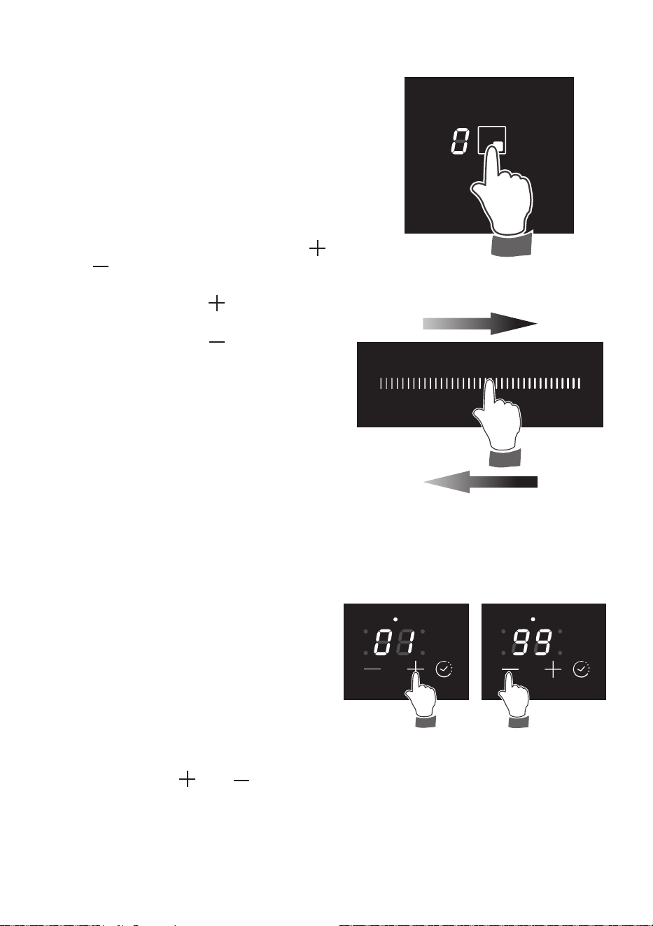
This function permits to set a timer from “ 1 ”
to “ 99 ” minutes for automatic turning O the
cooking zone/s.
With the cooktop switched On:
• Select the cooking zone and set the
desired power level.
• Within 8 seconds, touch the timer key
or (the led indicating the programmed
zone starts blinking) and set the timer:
By pressing the key the initial value
is “ 0 ” .
By pressing the key the initial value
is “ 99 ”.
• The time can be changed at any time
following the same procedure here
above indicated (selecting previously the
cooking zone).
• To program another cooking zone,
repeat as described above.
NOTE: The led indicating the cooking
zone closest to the end of the program, is
blinking. In the case of one programmed
zone only, the led is blinking.
Now the program for automatic switching O
is complete.
At the end of the countdown the cooking
zone will switch O automatically, an acoustic
signal (beep) will sound (for 1 minute only),
“
00 ” will ash on the timer display and the
led next to the timer display (indicating the
programmed zone) will blink.
Touch one of the keys to stop the beep.
The program for automatic switch O can be
cancelled at any time:
• by resetting the timer to “ 00 ”).
• by pressing the
and
keys at the
same time.
Fig. 2.12
Fig. 2.13
Fig. 2.14
Increase
Decrease
2929
“FAST HEATING” FUNCTION
To activate the “Fast Heating” function:
• Press the key and keep it pressed until the touch control is lighted.
• Select a cooking zone by touching the relevant display of the cooking zone to be used.
• Select a setting on the selector (between “ 1 ” and “ 9 ”): touch at one point to “jump” to
a specic setting or slide your nger along the selector (g. 2.7) and press for several
seconds, the operation is indicated by an acoustic signal (beep). The cooking zone
display alternates between set power level and
.
This function allows the cooking zone to operate at the maximum power (100%) for a time
proportional to the selected power level; after this time the cooking zone will operate at the
selected level.
This function is available on all the cooking zones.
While this function is operating it is possible, at any time, to increase the selected power
level but it is not possible to decrease the power; by touching the selector to a lower level
the function will be disabled.
The function will be disabled also by press the key
or by selecting the “Booster” function.
Fig. 2.15
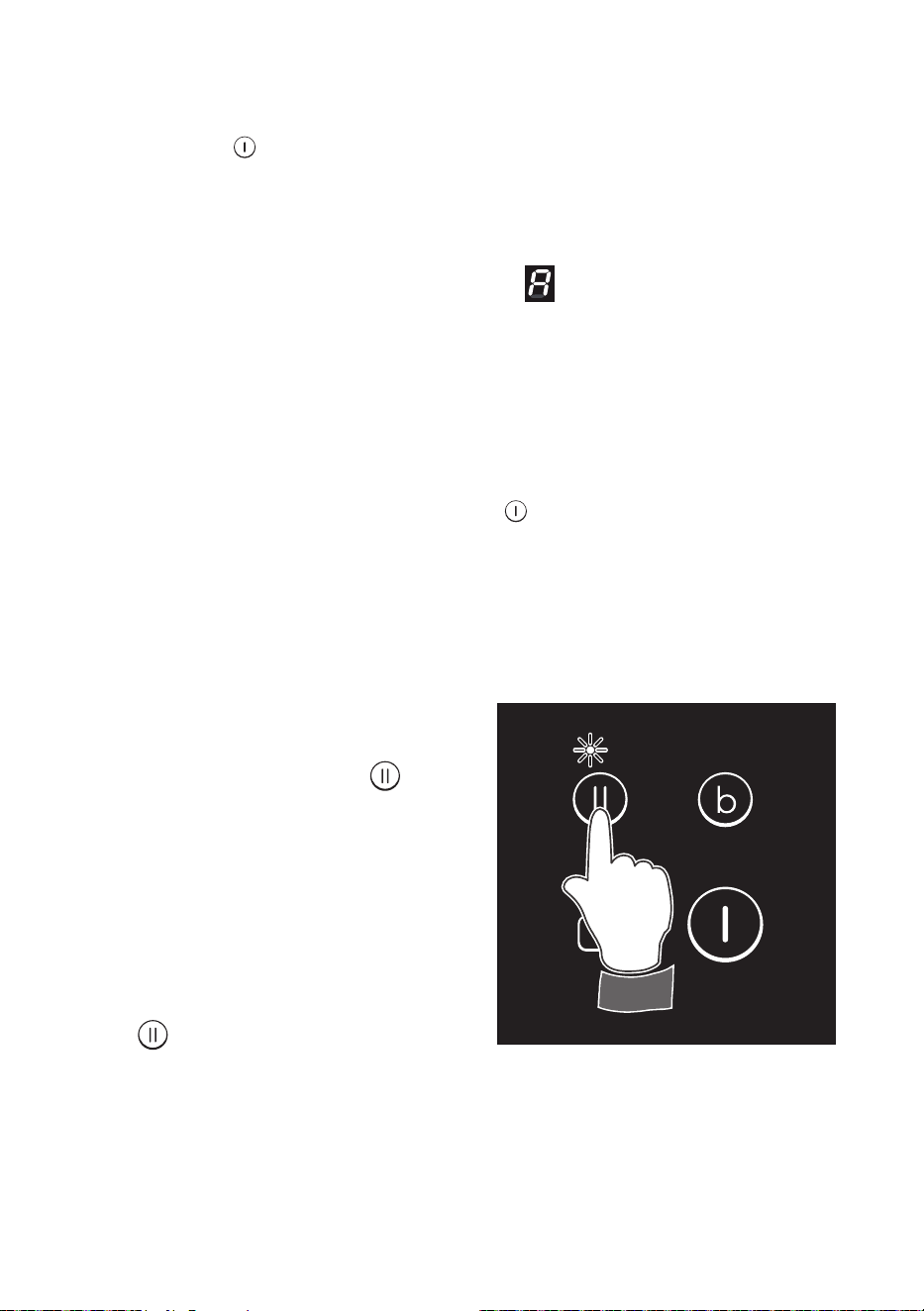
PAUSE MODE
When at least one cooking zone is in
operation, the cooking may be paused
temporarily by touching the key (g.
2.15).
Already programmed automatic cookings
are stopped and do not continue during the
pause. The displays show a zero iterative
(the leds light up in sequence).
The pause mode may last for max
10 minutes. If the pause mode is not
terminated within the time, the cooktop
switches O automatically.
To deactivate the pause mode touch again
the key
.
The cooktop may be switched O at any
time with the On/O key; any possibly
program already set (pause mode included)
is then terminated.
IMPORTANT: It is not possible to
activate the key-lock with the pause
mode.
3030
1
2
3
4
5
6
7
8
9
10
11
12
Fig. 2.16
After a short period of use, experience will
teach you which setting is the right one for
your needs.
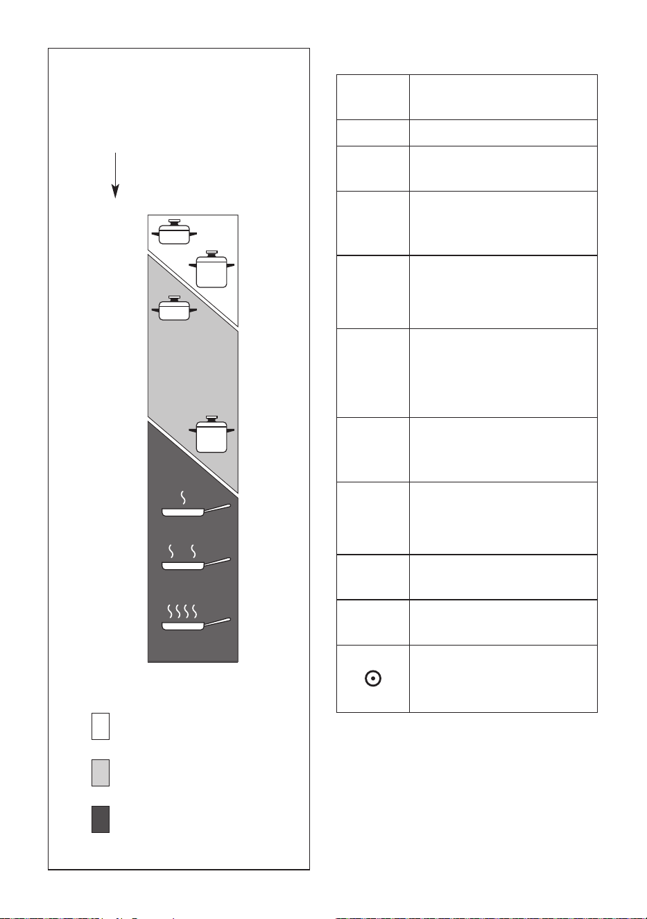
COOKING HINTS
Knob
setting
TYPE OF COOKING
0 Switched OFF
1
2
For melting operations
(butter, chocolate).
3
To maintain food hot and to
heat small quantities of liquid
(sauces, eggs).
4
5
To heat bigger quantities;
to whip creams and sauces
(vegetables, fruits, soups).
5
6
Slow boiling, i.e.: boiled
meats, spaghetti, soups,
continuations of steam
cooking of roasts, stews,
potatoes.
6
For every kind of frying,
cutlets, uncovered cooking,
i.e.: risotto.
7
8
Browning of meats,
roasted potatoes, fried sh,
omelettes, and for boiling
large quantities of water.
9
Fast frying, grilled steaks,
etc.
P
Rapidly heat up large
amount of water.
Switching on the second
element (Double radiant
plate only).
Heating
Cooking
Roasting-frying
Cooking
zone
power
level
1
2
3
4
5
6
7
8
9
P
3131
Figure 21
SAFETY HINTS
• Before you switch the hob on, make
sure you know which knob controls the
required cooking zone. We advise you
to set the pan over the cooking zone
before switching it on.
• Do not use pots and pans with rough
bases (pay attention to cookware
made of cast-iron). Rough bases can
damage the glass surface of the hob
(scratches).
• Always ensure that the base of your
saucepan is clean and dry before
placing on the hob.
• Pots with aluminium bottoms may
leave silver streaks or spots on the
hob.
• Do not leave wet or damp lids on the
hob.
• The glass-ceramic surface and pans
must be clean. Carefully eliminate any
food remains (especially containing
sugar), dirt etc. with the aid of a
cleansing agent.
• Pan handles should never stand out
beyond the kitchen worktop, as there
is a great danger of knocking the pan
over. This will also ensure that children
cannot reach them.
• Do not use the hob if the glass
surface is broken or cracked in any
way. Please disconnect the hob
from the mains and contact the
After-Sales Service.
• Do not lean over the cooking plate
when in use.
• Do not lay cooking foil or plastic
materials on the ceramic surface when
it is hot.
• Remember that the surface remains
hot for a long time (about 30 min.) after
the cooking plate has been switched
o.
• Follow the cleaning instructions
carefully.
• Never use the glass surface for storage.
DISTORTED
PANBASE
WRONG
DISTORTED
PANBASE
WRONG
LEVEL
PANBASE
CORRECT
WRONG
WASTING
POWER
WRONG
WASTING
POWER
WRONG
WASTING
POWER
CORRECT
COMPLETE USE
OF THE HEAT
DO NOT USE GLASSWARE ON CERAMIC
HOBS. DO NOT USE PANS WITH ROUGH
CIRCULAR MACHINED BASE.
Fig. 2.18
Fig. 2.17
3232
Power level of
Cooking zones
Operation
time limit
10 hours
5 hours
5 hours
4 hours
3 hours
2 hours
2 hours
2 hours
1 hour
10 minutes
OPERATION TIME LIMIT OF
COOKING ZONES
Each cooking zone is automatically
switched OFF after a maximum preset time
if no operation is performed.
The maximum preset time limit depends
on the set power level, as illustrated in this
schedule.
Each operation on the cooking hob by
using the keys and , will reset the
maximum operation time at its initial value.
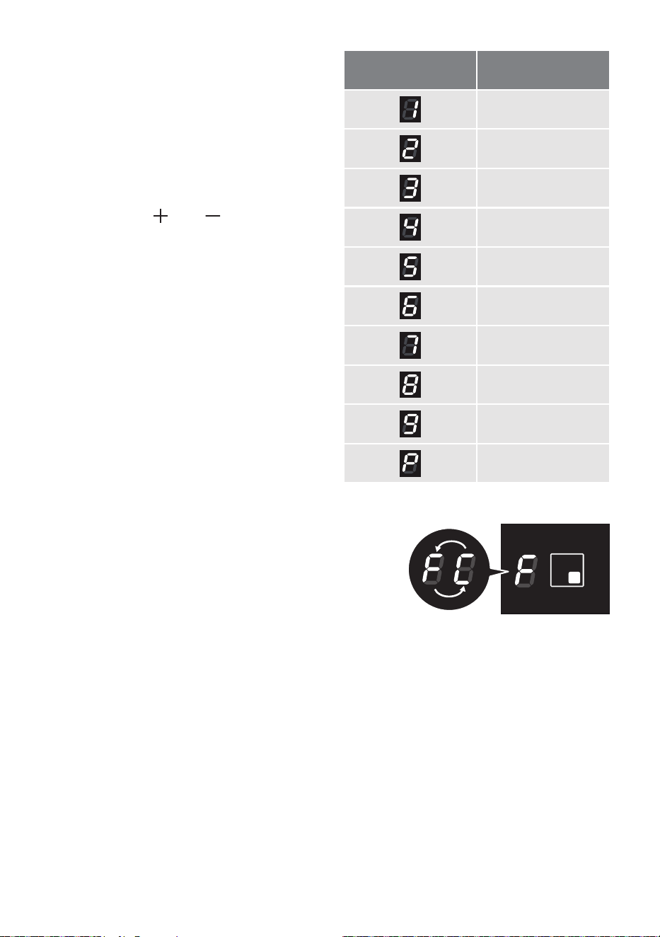
ERROR CODE ON THE DISPLAY/S
If an error message appears on the display/s (the
display/s show/s “
F “ and another character alternating
- e.g. “
F “ and “ C “, “ F “ and “ 0 “, .....) :
1. Disconnect the cooktop from the mains.
2. Reconnect the cooktop and turn it on.
3. Wait for about two minutes and if the problem does not appear the cooktop can be
used.
4. If the problem does not disappear repeat step from 1 to 3.
5. If the problem continues, disconnect the cooktop from the mains and contact your
Authorised Service Centre.
DISPLAY/S OFF OR NOT CORRECTLY OPERATING
If a display or the displays are only partially lit or not lit.
1. Switch o the cooktop and disconnect it from the mains.
2. Reconnect the cooktop and turn it on.
3. Wait for about two minutes and if the problem does not appear the cooktop can be
used.
4. If the problem does not disappear repeat step from 1 to 3.
5. If the problem continues, disconnect the cooktop from the mains and contact your
Authorised Service Centre.
3333
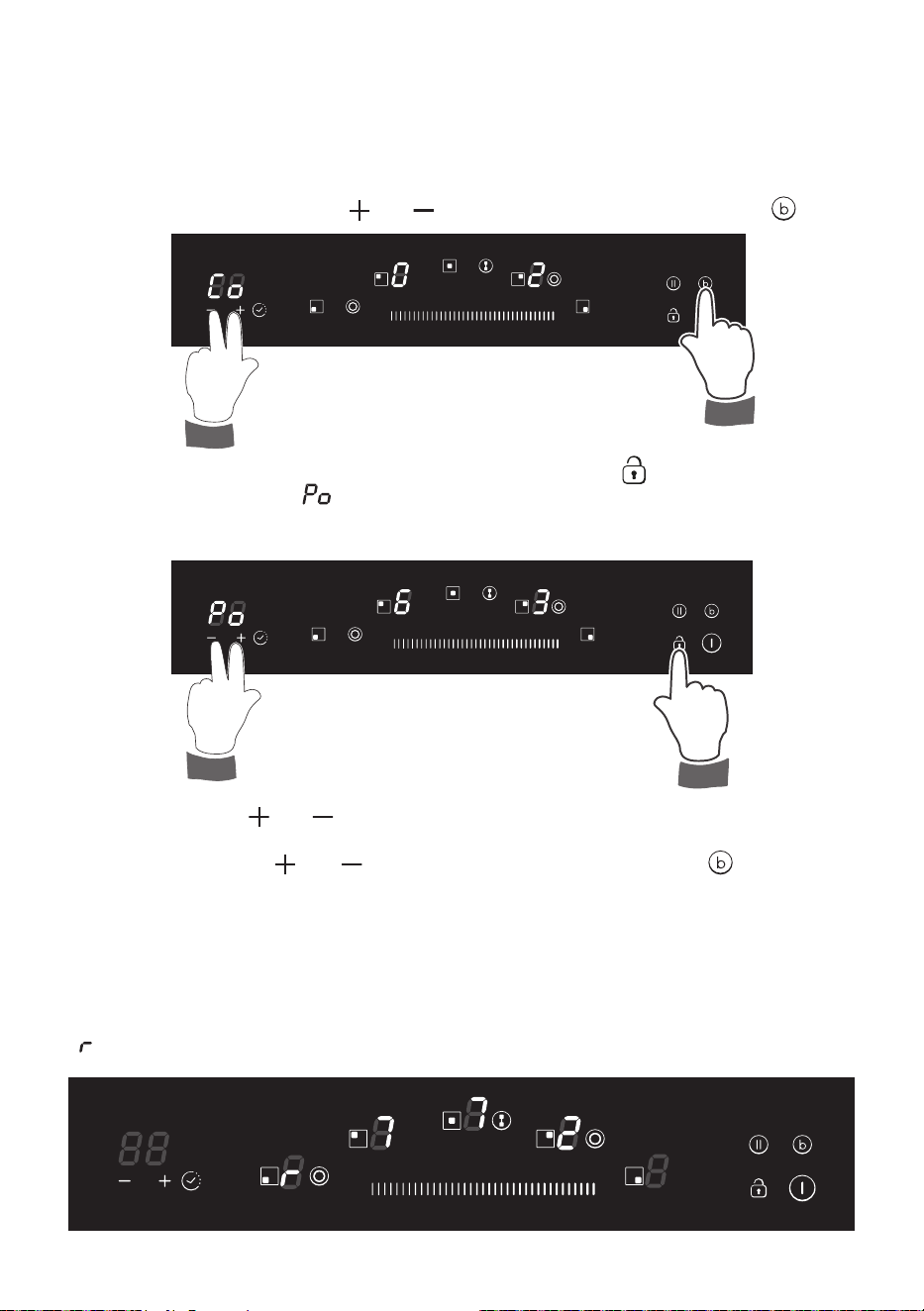
MAXIMUM POWER MANAGEMENT
The cooktop maximum power limit (6300 W for model in g. 1.1 or 8500 W for model in g.
1.2) can be reduced to a minimum of 2500 W.
To change the maximum power limit (only within 30 seconds from the electrical connection):
• Connect the appliance to the electrical power supply.
• Press at the same time the and keys controlling the timer and the key .
• Once the beep sounds, release the keys and press the key ; A beep sounds and the
timer display shows “ ”: the current set maximum power limit can be read on the
displays of the rear cooking zones (e.g. rear left zone = “6 ” and rear right zone = “3 ”
: maximum power limit = 6300 W).
POWER MANAGEMENT WHEN USING THE COOKTOP
When using one or more cooking zones if the total power set on the zones is greater than
the maximum power limit, an acoustic signal (beep) sounds and the last set zone shows
“ ” for 3 seconds; then the power of that zone is automatically reduced within the allowed limit.
• Touch the keys or for selecting a new maximum power limit. Then, to set the
new maximum power limit (shown on the displays of the rear cooking zones) press at
the same time the and keys controlling the timer and the key . If this is not
done within 120 seconds, the system resets automatically and the new power limit is
not set.
3434
GENERAL ADVICE
• Before you begin cleaning, you must ensure that the appliance is switched o
and disconnected from the electrical power supply.
• It is advisable to clean when the appliance is cold.
• Avoid leaving alkaline or acidic substances (lemon juice, vinegar, etc.) on the surfaces.
• Avoid using cleaning products with a chlorine or acidic base.
• Do not use a steam cleaner because the moisture can get into the appliance thus
make it unsafe.
• Important: The use of suitable protective clothing/gloves is recommended when
handling or cleaning of this appliance.
• Do not scratch the cooktop with cutting or sharp objects.
• Important: The manufacturer declines all liability for possible damage caused by
the use of unsuitable products to clean the appliance.
• Clean surfaces with a damp cloth and use gentle, neutral cleaning products. Dry with
a clean, dry cloth.
• IMPORTANT: Do not use any abrasive products (e.g. certain types of sponge) and/
or aggressive products (e.g. caustic soda, products containing corrosive substances),
which could cause irreparable surface damage.
WARNING!
When correctly installed, your product meets all safety requirements laid down for
this type of product category. However special care should be taken around the
underneath of the appliance as this area is not designed or intended to be touched
and may contain sharp or rough edges, that may cause injury.
CLEANING THE CERAMIC HOB
• Remove spillages and other types of incrustations.
• Dust or food particles can be removed with a damp cloth.
• If you use a detergent, please make sure that it is not abrasive or scouring. Abrasive or
scouring powders can damage the glass surface of the hob.
• All traces of the cleaner must be removed with a damp cloth.
• Dust, fat and liquids from food that has boiled over must be removed as soon as
possible.
• If they are allowed to harden they become increasingly dicult to remove.
This is especially true in the case of sugar/syrup mixtures which could permanently pit
the surface of the hob if left to burn on it.
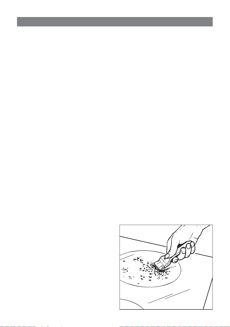
• If any of these products has melted on
the ceramic surface, you should remove
it immediately (when the surface is still
hot) by using a proper scraper to avoid
any permanent damage to the surface
of the hob.
• Do not put articles on the hob which can
melt: i.e plastic, aluminium foil, sugar,
sugar syrup mixtures etc.
• Avoid using a knife or other sharp utensil
as these may damage the ceramic
surface.
• Do not use steel wool or an abrasive
sponge which could scratch the surface
permanently.
CLEANING AND MAINTENANCE
3
Fig. 3.1

3535

Cod. 1106443/GB - ß0
The manufacturer will not be responsible for any inaccuracy resulting from printing or transcript errors
contained in this brochure. We reserve the right to carry out modications to products as required,
including the interests of consumption, without prejudice to the characteristics relating to safety or
function.
GB