
AC-EXO-X-PLUS-KIT
User Manual
48 Gbps 8K Fiber Optic Extender Kit with USB, eARC & Ethernet

AC-EXO-X-PLUS-KIT User
Manual
Page 2 23
Contents
Important Safety Instructions ............................................................................................................................................................................ 4
Safety Classifications in this Document .................................................................................................................................................. 4
Electrical Shock Prevention ........................................................................................................................................................................... 4
Weight Injury Prevention ............................................................................................................................................................................... 4
Safety Statements ............................................................................................................................................................................................ 5
Introduction ................................................................................................................................................................................................................. 6
Features ................................................................................................................................................................................................................... 6
Product Overview .................................................................................................................................................................................................... 7
Box Contents ......................................................................................................................................................................................................... 7
Technical
Specifications ............................................................................................................................................................................... 7
Transmitter Front and Rear Panel Overview ............................................................................................................................... 9
Receiver Front and Rear Panel Overview .................................................................................................................................... 11
Wiring and Connections ................................................................................................................................................................................. 13
HDMI Cables ...................................................................................................................................................................................................... 13
USB Ports ............................................................................................................................................................................................................ 13
RS-232 Wiring .................................................................................................................................................................................................... 13
IR Wiring ............................................................................................................................................................................................................... 14
Power Connections ........................................................................................................................................................................................ 15
Fiber Optic Cables ....................................................................................................................................................................................... 16
Types of Fiber ............................................................................................................................................................................................... 16
OM Grades ..................................................................................................................................................................................................... 16
Connector Types ......................................................................................................................................................................................... 16
Installation ................................................................................................................................................................................................................. 17
General Application ...................................................................................................................................................................................... 17
Settings and
Functionalities ......................................................................................................................................................................... 17
EDID Management (Transmitter) ....................................................................................................................................................... 17
Test Pattern ........................................................................................................................................................................................................ 18
Audio Extraction/Extension ........................................................................................................................................................................ 18
Transmitter Audio Settings .................................................................................................................................................................... 18
Receiver Audio Settings .......................................................................................................................................................................... 19
Ethernet Extension .......................................................................................................................................................................................... 19
Ethernet Indicator Lights ........................................................................................................................................................................ 19
Command List ........................................................................................................................................................................................................ 20
Troubleshooting ..................................................................................................................................................................................................... 21
Maintenance ............................................................................................................................................................................................................ 21

AC-EXO-X-PLUS-KIT User
Manual
Page 3 23
Damage
Requiring Service ........................................................................................................................................................................... 21
Support ....................................................................................................................................................................................................................... 22
Warranty .................................................................................................................................................................................................................... 22
The Basics ........................................................................................................................................................................................................... 22
Coverage Details ............................................................................................................................................................................................ 22
Red Tape .............................................................................................................................................................................................................. 22
Obtaining an RMA ......................................................................................................................................................................................... 23
Shipping ................................................................................................................................................................................................................ 23
Limitation on Liability ................................................................................................................................................................................... 23
Exclusive
Remedy .......................................................................................................................................................................................... 23

AC-EXO-X-PLUS-KIT User
Manual
Page 4 of
23
Important Safety Instructions
Before installing, configuring, and operating the devices and other vendor equipment, AVPro Edge
strongly recommends that each dealer, integrator, installer, and all other necessary personnel access
and read all the required technical documentation, which can be located by visiting AVProEdge.com.
Read and understand all safety instructions, cautions, and warnings in this document and the labels on
the equipment.
Safety Classifications in this Document
Note:
Provides special information for installing, configuring, and operating the
devices and equipment.
Tip:
Provides suggestions and considerations for installing, configuring, and
operating the devices and equipment.
Important:
Provides special information that is critical for installing, configuring, and
operating the devices and equipment.
Caution:
Provides special information for avoiding situations that may cause
damage to the devices and equipment.
Warning:
Provides special information for avoiding situations that may cause
physical danger to the installer, end user, etc.
Electrical Shock Prevention
Weight Injury Prevention
Weight
Injury:
Installing some of the devices and equipment requires two installers
to
ensure safe handling during installation. Failure to use two
installers may result in injury.
Electric Shock:
Provides special information that is critical for installing, configuring, and
operating the devices and equipment.
Electrical
Disconnect:
Provides special information for avoiding situations that may cause
damage to the devices and equipment.

AC-EXO-X-PLUS-KIT User
Manual
Page 5 of
23
Safety Statements
Follow all the safety instructions listed below and apply them accordingly. Additional safety
information will be included where applicable.
1 Read and keep these instructions.
2 Heed and follow all warnings.
3 Clean devices and equipment only with a dry cloth.
4 Do not use the devices near water or expose them to rain and moisture.
5 Do not block any ventilation openings.
6 The devices and their accessories should never be exposed to open flames or excessive heat.
7 Only use attachments and accessories specified by the manufacturer.
8 Install in accordance with the manufacturer’s instructions.
9 Do not install near any heat sources, such as radiators, heat registers, stoves, or other
apparatus that produce heat.
10 Do not defeat the safety purpose of the polarized / grounding-type plug. A polarized plug has
two blades with one wider than the other. A grounding-type plug has two blades and a third
grounding prong. The wide blade, or third prong, are provided for your safety.
11 Protect the power cord from being walked on or pinched, particularly at plugs, convenience
receptacles, and the point where they exit from the devices.
12 Unplug the devices during lightning storms or when unused for long periods of time.
13 To reduce the risk of electrical shock or damage to the devices and their operators, never
handle or touch the devices and power cord with damp or wet hands.
14 To reduce the risk of injury, some of the devices and equipment may require two installers to
ensure safe handling during installation. Failure to use two installers may result in injury.
15 Refer all servicing to qualified service personnel. Servicing is required when the devices have
been damaged in any way, such as the power cord or plug is damaged, liquid has been
spilled, objects have fallen into the devices, the devices have been exposed to rain or
moisture, do not operate normally, or have been dropped.
AC-EXO-X-PLUS-KIT User
Manual
Page 6 of
23
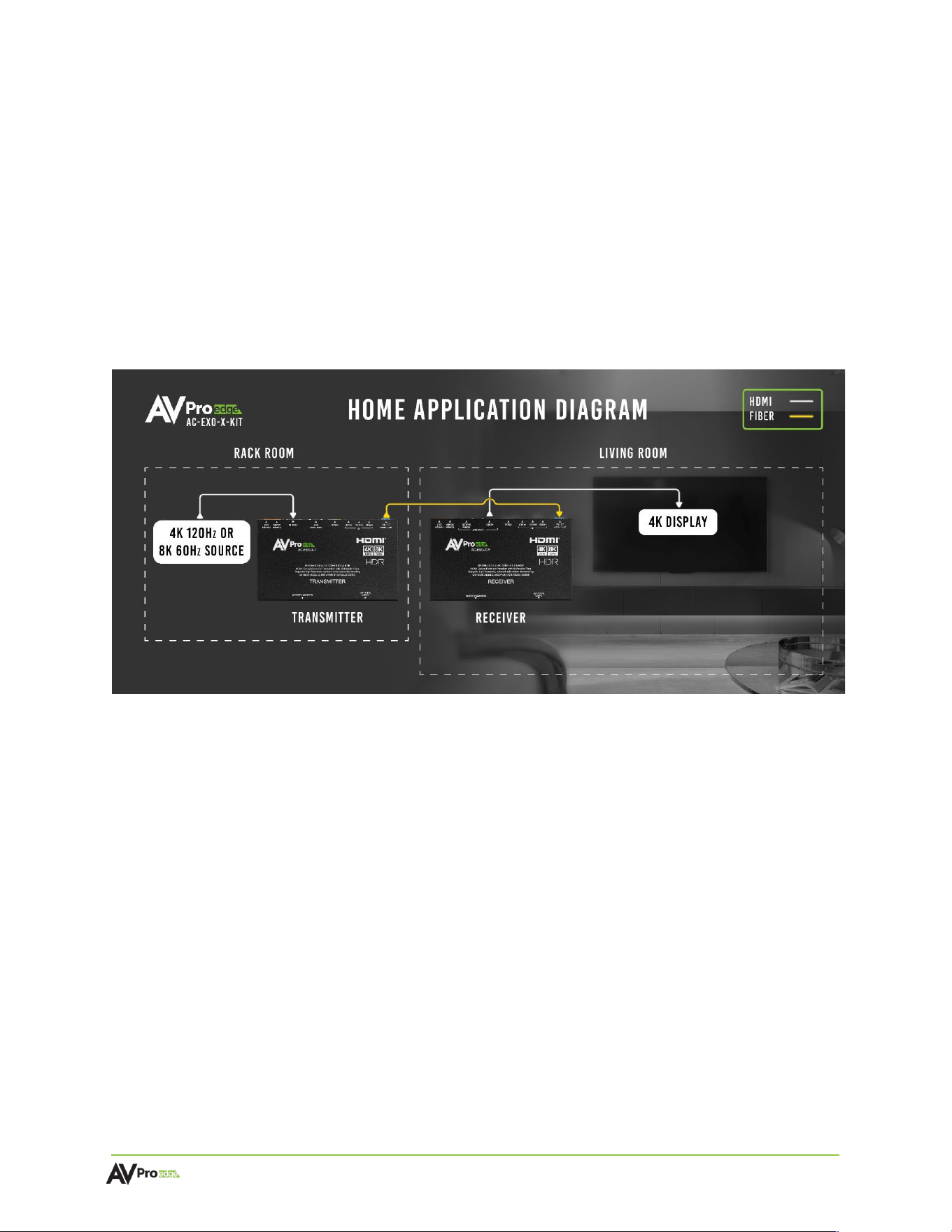
Introduction
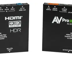
The AC-EXO-X-PLUS-KIT is a pair of 48 Gbps transmitter and receiver modules that extend HDMI 2.1
video and audio signals over a single multimode fiber optic cable. The maximum supported video
resolutions are up to 8K 60 Hz 4:2:0 or 4K 120 Hz 4:4:4 with 7.1 audio. Supported HDMI 2.1 features
include Auto Low Latency and Variable Refresh Rate, along with 16 EDID presets and a built-in test
pattern that can be enabled using the dipswitches on the transmitter. The AC-EXO-X-PLUS-KIT
supports USB 2.0, eARC and Ethernet extension. USB extension adds KVM functionality, by extending
USB signals like a keyboard and mouse to a remote PC. eARC can be used for audio extraction to AVR
and surround sound systems. Ethernet extension acts as an ethernet hub, bringing LAN connectivity to a
display or devices local to the display.
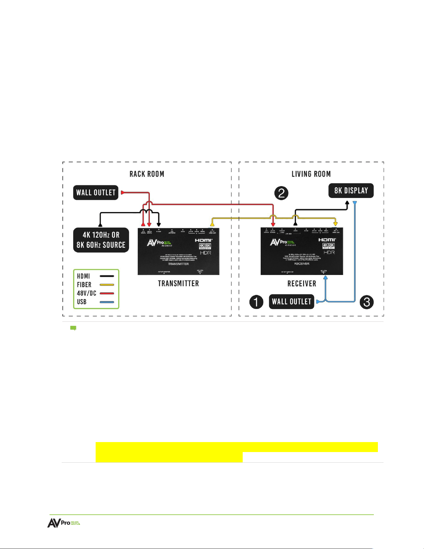
The diagram below shows the basic application of the AC-EXO-X-PLUS-KIT.
Features
•
Multimode fiber grade OM2 / 3 / 4 compatible, up to 300 meters
•
8K 48 Gbps bandwidth (8K 60 Hz 4:2:0) / High Frame Rate 4K 120 Hz 4:4:4
•
HDMI 2.1 support for Auto Low Latency and Variable Refresh Rate
•
Supports HDR formats, including Dolby Vision, HDR10 & HDR10+, and HLG
•
AVPro Edge’s custom algorithm monitors Fixed Rate Link status and restrains Link Training
bandwidth reductions
•
Comprehensive EDID management for mixed-resolution Next-gen systems
•
USB 2.0, eARC and Ethernet extension for KVM, audio extraction, and LAN connectivity.
•
RS-232 and IR Bidirectional Passthrough
AC-EXO-X-PLUS-KIT User
Manual
Page 7 of
23
Product Overview
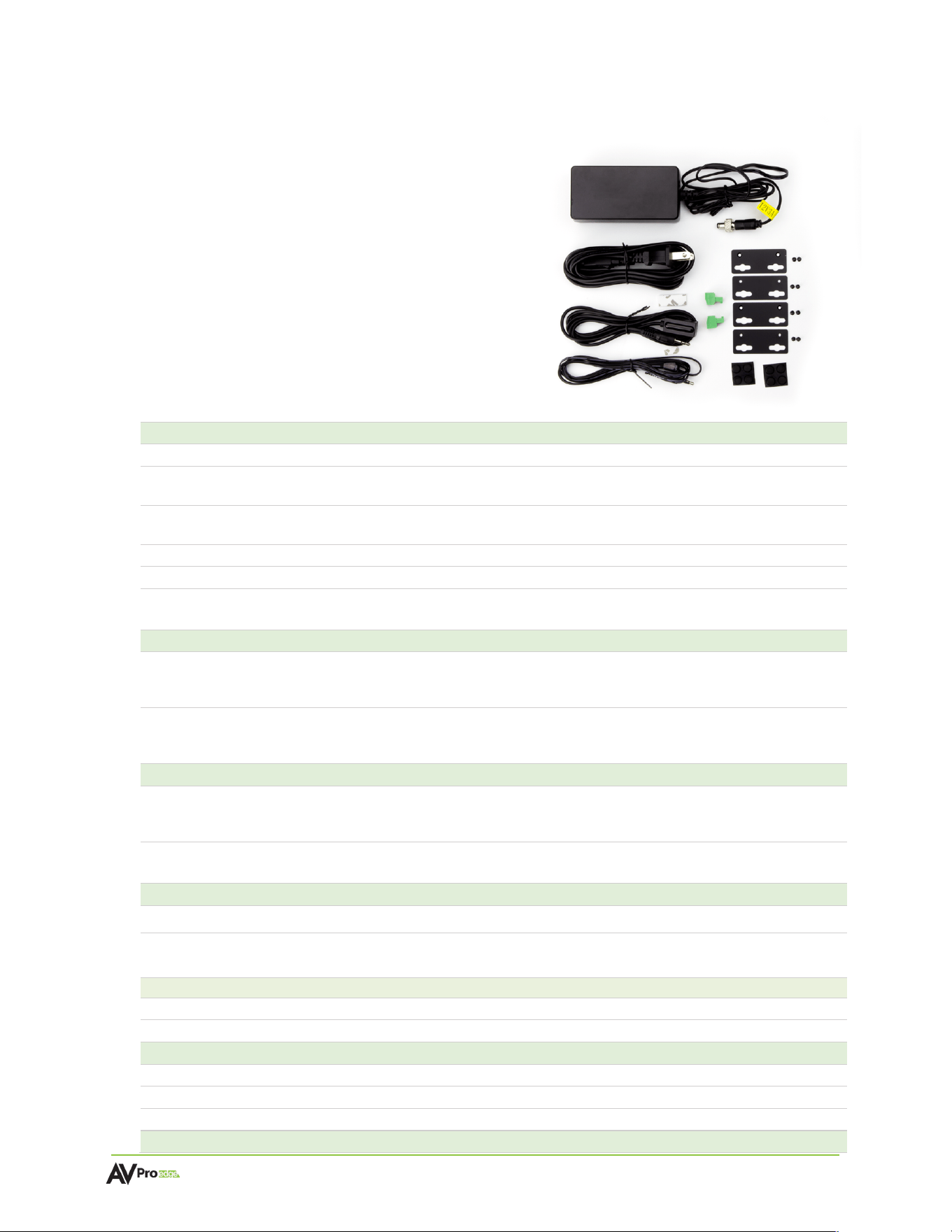
Box Contents
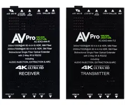
(1x) Fiber Optic Transmitter Module AC-EXO-X-PLUS-T
(1x) Fiber Optic Receiver Module AC-EXO-X-PLUS-R
(1x) 12v 3a Power Supply
(1x) Stereo IR Eye
(1x) Mono IR Emitter
(1x) USB Type-C to USB Type-A Cable
(2x) 2-Pin Terminal Block Connector
(2x) 3-Pin Terminal Block Connector
(4x) Mounting Brackets
(8x) Mounting Bracket Screws
Technical
Specifications
Video
Video Resolutions
Up to 8K 60 Hz 4:2:0, 8K 30 Hz 4:4:4, 4K 120 Hz 4:4:4
HDR Formats
Dolby Vision, HDR10, HDR10+, HLG
Color Space
YUV (Component), RGB
(CSC: ITU-R BT.601, ITU-R BT.709, ITU-R BT.2020, DCI-P3 D65)
Chroma Subsampling
4:4:4, 4:2:2, 4:2:0
Color Bit Depth
Up to 16-bit
Downscaling
8K / 4K to 1080p
Audio
Audio Formats Supported (HDMI)
PCM 2.0-Ch, LPCM 5.1 & 7.1, Dolby Digital, Dolby Digital
Plus, Dolby TrueHD, Dolby Atmos, DTS 5.1, DTS-HD
Master Audio, DTS:X
Audio Formats Supported Extracted (TOSLINK)
LPCM up to 5.1, 96 kHz 24-bit, Dolby Digital 5.1, DTS High
Resolution Audio
ARC / earc
Formats Supported (HDMI)
PCM 2.0-Ch, LPCM 5.1 & 7.1, Dolby Digital, Dolby Digital
Plus, Dolby TrueHD, Dolby Atmos, DTS 5.1, DTS-HD
Master Audio, DTS:X
Formats Supported (TOSLINK)
PCM 2.0-Ch, LPCM 5.1 & 7.1, Dolby Digital, DTS 5.1, Dolby
Digital Plus, Dolby TrueHD
USB Extension
Version
USB 2.0
Ports
(1) USB HOST, USB Type-C (Transmitter)
(4) USB DEVICE, USB Type-A (Receiver)
Ethernet Extension
Bandwidth
1Gbps
Port
RJ45
Fiber
Type
Multimode OM3
Connector
Simplex LC (Lucent Connector)
Recommended Fiber
OM3 Cleerline SFF™ Fiber
Distance

AC-EXO-X-PLUS-KIT User
Manual
Page 8 of
23
OM2
Up to 40 m
OM3
Up to 200 m
OM4
Up to 300 m
HDMI In/Out (4K/60 Hz 4:4:4)
Up to 50 ft. (using Bullet Train© HDMI)
HDMI In/Out (w/ with AOC Cable) (4K/60Hz 4:4:4)
Up to 130 ft. (using Bullet Train© AOC)
Other
Bandwidth
48 Gbps (FRL6)
HDCP
HDCP 2.3 and earlier
Ports
HDMI
HDMI Type-A 19-pin, female
Audio (Extracted Digital)
TOSLINK
USB
(1) USB Type-C (Transmitter)
(4) USB Type-A (Receiver)
Ethernet
RJ45
IR TX
3.5 mm Mono (2-Conductor)
IR RX
3.5 mm Stereo (3-Conductor)
RS-232
3-pin Euroblock
Firmware
USB-C
POC
RJ45
Power In
Barrel Connector
Environmental
Operating Temperature
23° to 125° F (-5° to 51° C)
Storage Temperature
-4° to 140° F (-20° to 60° C)
Humidity Range
5-90% RH (no condensation)
Power
Total Power Consumption
12 W Maximum
Power Supply
Input: 12 VDC/3a Power Supply
Output: 12v 3a
Physical / Dimensions
Mounting
Mounting Brackets (screws included)
Dimensions (Unit Height x Width x Depth)
mm: 109.55 X 181.10 X 22.22
inches: 4.31 X 7.13 X .87
Dimensions (Packaged Height x Width x Depth)
mm: 314.45 x 184.15 x 77.98
inches: 12.38 x 7.25 x 3.07
Weight (Unit)
1.144 lbs. (0.52 kg)
Weight (Packaged)
3.8 lbs. (1.7 kg)
Regulatory
CE/FCC
Product Warranty
10 Years
*Specifications are subject to change without notice. Mass and dimensions are approximate.
AC-EXO-X-PLUS-KIT User
Manual
Page 9 of
23
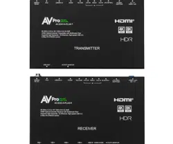
Transmitter Front and Rear Panel Overview
AC-EXO-X-PLUS-T Front Panel
AC-EXO-X-PLUS-T Rear Panel
1
USB-C
• USB 2.0 Type-C HOST connector
• USB output to devices or hub
2
Power Light
• Blue LED status indicator light
• Solid blue indicates power is present on the transmitter
3
Optical Link Light
• Blue LED status indicator light has 3 states:
Off: There is no data connection or link established
Flashing: Data connection and link are established, but no video
Solid On: Data connection and link are established, video is present
4
HDMI In Light
• Blue LED status indicator light
• Solid blue indicates an active signal is present on the HDMI In port
5
LC / TX Opt. Fiber
• LC Simplex multimode fiber connector port
• Connects to LC / RX port on the receiver (AC-EXO-X-PLUS-R)
6
HDMI In
• 19-pin HDMI Type-A female connector port
• Source input with HDMI or ARC/eARC connection
7
TOSLINK Out
• TOSLINK output connector port
• Output extracted audio to external audio processor
8
I-PASS
• 3.5mm stereo jack (TRS) IR receiver port
• Sends IR signals via a direct connection from a control system
processor to the IR output of the desired endpoint(s)
9
IR-EYE
• 3.5mm stereo jack (TRS) IR receiver port
• Supports an IR eye connection to capture IR signals from a control
system processor or third-party remote to send IR signals to the IR
output of the desired endpoint(s)
10
IR-Out
• 3.5mm mono jack (TS) IR transmitter port
• Sends IR signals upstream to the output of the desired endpoint(s)

AC-EXO-X-PLUS-KIT User
Manual
Page 10 of
23
11
ISP / CTRL USB-C
• USB Type-C female connector port
• Secondary power input to power the transmitter
• Servicing port for AVPro Edge Technical Support
12
RS-232
• 3-pin terminal block connector port
• Serial RS-232 control port
13
Ethernet
• 1GB RJ45 ethernet connection
• Pass LAN connectivity between transmitter and receiver. Connecting to
devices enables network and/or internet access.
14
POC
• Power over cable supports power delivery over RJ45 between
transmitter and receivers POC ports.
15
Power In
• Power 12v 3a In port supports local power to the transmitter
AC-EXO-X-PLUS-KIT User
Manual
Page 11 of
23
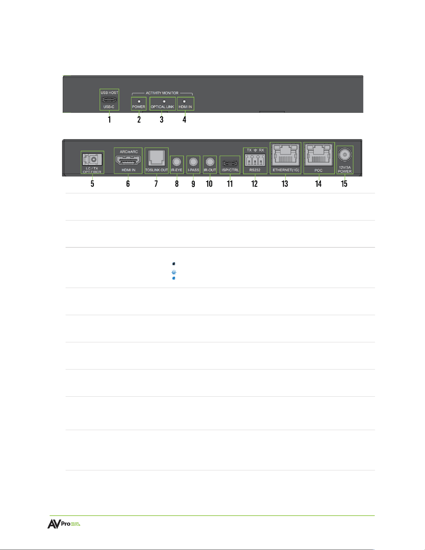
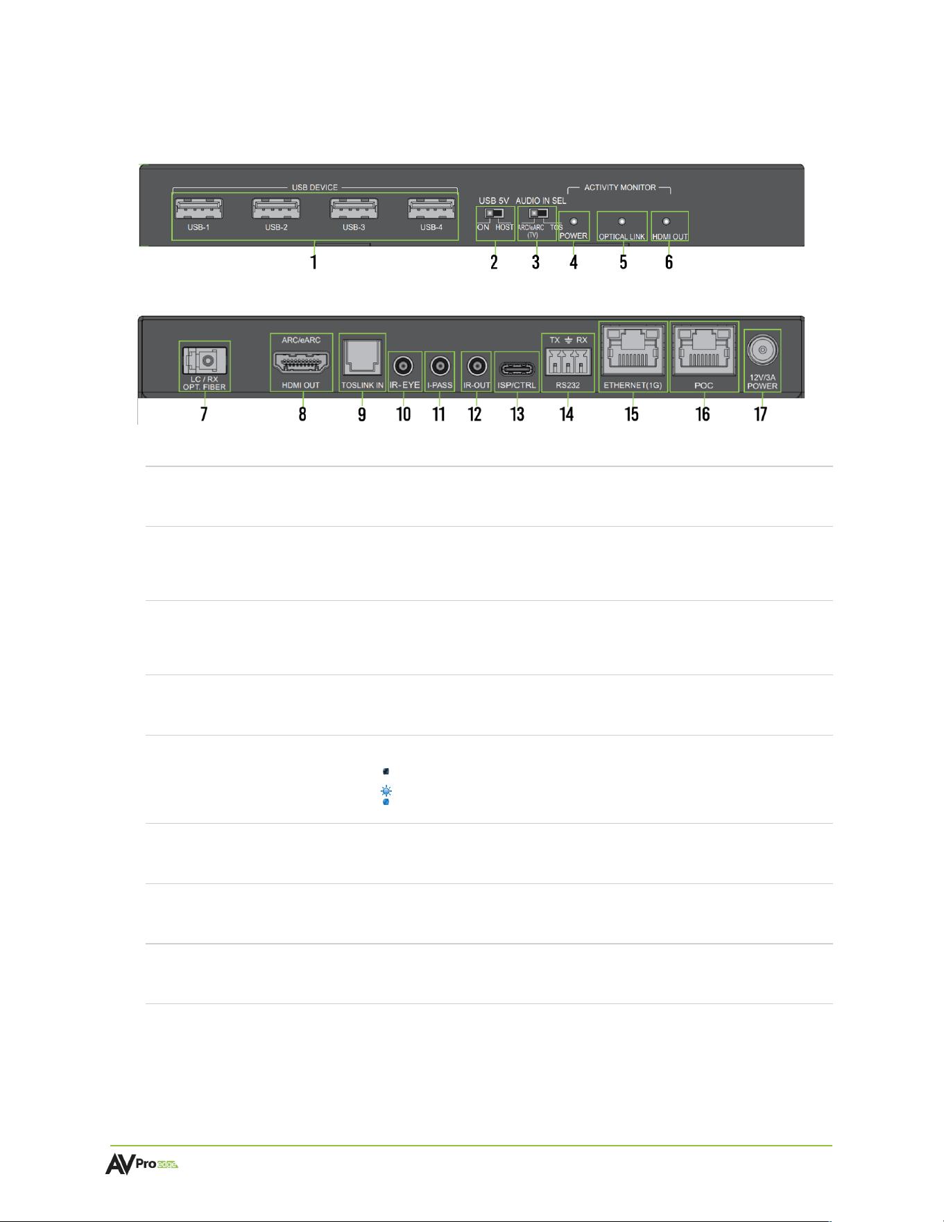
Receiver Front and Rear Panel Overview
AC-EXO-X-PLUS-R Front Panel
AC-EXO-X-PLUS-R Rear Panel
1
USB Device Ports
• (4) USB 2.0 Type-A Device Ports
2
USB 5V Dipswitch
• Dipswitch to control 5V output on USB Device ports
• Setting to ON outputs 5V when device is powered.
• Setting to HOST output 5V when HOST device is active.
3
Audio In Selection
Dipswitch
• Dipswitch to select audio input source
• Setting to ARC/eARC (TV) sources audio signal from display (HDMI)
• Setting to TOS sources audio signal from TOSLINK IN port
4
Power Light
• Blue LED status indicator light
• Solid blue indicates power is present on the receiver
5
Optical Link Light
• Blue LED status indicator light has 3 states:
Off: There is no data connection or link established
Flashing: Data connection and link are established, but no video
Solid On: Data connection and link are established, video is present
6
HDMI Out Light
• Blue LED status indicator light
• Solid blue indicates an active signal is present on the HDMI 1 port
7
LC / RX Opt. Fiber
• LC Simplex multimode fiber connector port
• Connects to LC / TX port on the transmitter (AC-EXO-X-PLUS-T)
8
HDMI OUT
• 19-pin HDMI Type-A female connector port
• HDMI output to display or ARC/eARC device
9
TOSLINK IN
• TOSLINK input connector port
• Input extracted audio from external audio source

AC-EXO-X-PLUS-KIT User
Manual
Page 12 of
23
10
IR-EYE
• 3.5mm stereo jack (TRS) IR receiver port
• Supports an IR eye connection to capture IR signals from a control
system processor or third-party remote to send IR signals to the IR
output of the desired endpoint(s)
11
I-PASS
• 3.5mm stereo jack (TRS) IR receiver port
• Sends IR signals via a direct connection from a control system
processor to the IR output of the desired endpoint(s)
12
IR-Out
• 3.5mm mono jack (TS) IR transmitter port
• Sends IR signals upstream to the output of the desired endpoint(s)
13
ISP / CTRL USB-C
• USB Type-C female connector port
• Secondary power input to power the receiver
• Servicing port for AVPro Edge Technical Support
14
RS-232
• 3-pin terminal block connector port
• Serial RS-232 control port
15
Ethernet
• 1GB RJ45 ethernet connection
• Pass LAN connectivity between transmitter and receiver. Connecting to
devices enables network and/or internet access.
16
POC
• Power over cable supports power delivery over RJ45 between transmitter
and receivers POC ports.
17
Power In
• Power 12v 3a In port supports local power to the receiver
AC-EXO-X-PLUS-KIT User
Manual
Page 13 of
23
Wiring and Connections
HDMI Cables
The AC-EXO-X-PLUS-KIT uses the standard 19-pin HDMI female connector ports for the inputs and outputs.
Note:
Ensure all HDMI cables and devices can support the signal being sent. For maximum
performance, an Ultra-High Speed HDMI cable rated for 48 Gbps will be more than
sufficient to satisfy signal transport if every device in the system can handle the signal.
Tip:
Ensure your HDMI cable is the correct length. The current HDMI specification calls for
cables to be between 2 to 10 meters (6.6 to 33 feet). Smaller wire cables may be unable to
transmit higher bandwidth signals like 4K 60 Hz over distances of even 5 meters (16 feet).
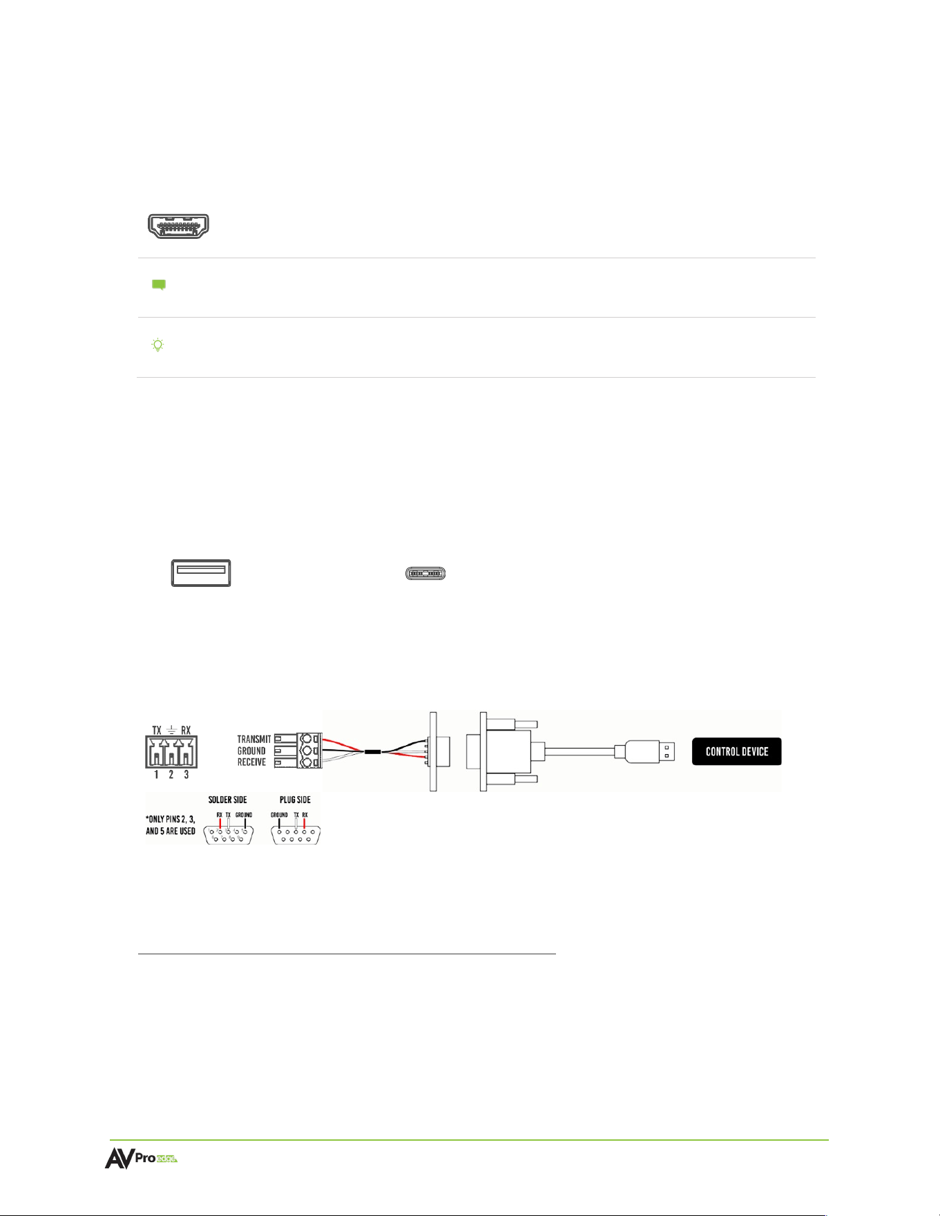
USB Ports
The Receiver has four USB 2.0 Type-A ports that can be connected to devices such as a mouse and
keyboard for KVM functionality. The Transmitter has a USB 2.0 Type-C port that can be connected to
a hub or directly to a PC or gaming console to extend the USB devices from the Transmitter.
Both the transmitter and receiver each have one USB Type-C port that functions as both a secondary
power input as well as a servicing port for AVPro Edge technical assistance in the event of testing and
troubleshooting.
USB Type-A USB Type-C
RS-232 Wiring
Serial control connections are made using the provided 3-pin terminal block connector. The wire slips
into the hole and locks with a screw located at the top of the connector.
Wiring for this port uses a 3-pin terminal block connector to DB9, where only pins 2, 3, and 5 are used.
If the control devices do not have a DB9 port, a USB to DB9 adapter may be required.
For RS-232 control, use a null modem serial cable adapter and set the serial communications to:
Baud: 57600, no parity, 8 data bits, 1 stop bit, no handshaking. Add a carriage return (Enter key) after
each command when using direct commands. The unified ASCII command list can be located here.
AC-EXO-X-PLUS-KIT User
Manual
Page 14 of
23
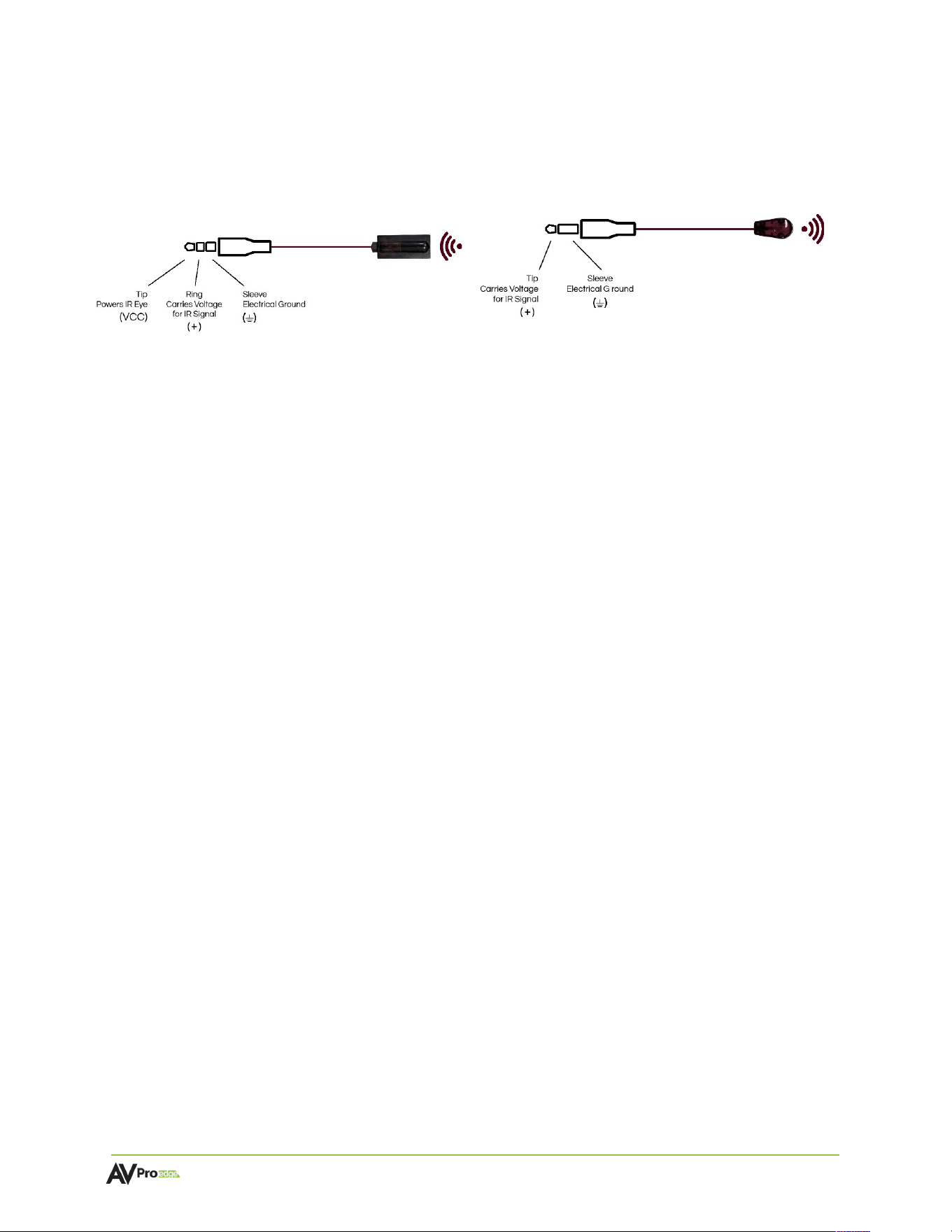
IR Wiring
IR connections are made using the provided 3.5mm IR Emitter and IR Eye (receiver.
Stereo 3.5mm (TRS) IR Eye Mono 3.5mm (TS) IR Emitter
IR can be used in three ways:
1 From Rack (Control System Direct): Connect a 3.5mm mono jack (TS) cable into an emitter
port of any control system directly into the
I-PASS
port on the transmitter to pass IR signals
directly to the remote end.
2 From Rack (Using IR-Eye): Connect the provided IR receiver eye cable into the
IR-EYE
port of
the transmitter to pass infrared signals generated from a device or IR remote.
3 From Remote End: Connect the provided IR receiver eye cable into the
IR OUT
port on the
receiver in order to send IR signals back to the rack and out of the transmitter’s
IR OUT
port
with an emitter.
AC-EXO-X-PLUS-KIT User
Manual
Page 15 of
23
Power Connections
Fiber optic cables do not carry electrical current and therefore cannot be used to power connected devices.
This kit includes one (1) 12V 3A power supply and features a POC (Power over Cable) RJ45 port, allowing power
to be sent over a single Cat6a cable (up to 100 meters) between units.
To power the system:
• Connect the included 12V 3A power supply to either the transmitter or the receiver.
• Use a Cat6a cable to link the POC RJ45 ports on both units. Power will be delivered from the powered
unit to the other over this connection.
Note
Using POC
• Connect Power Supply 12V 3A (TX or RX)
• Connect UPT cable recommended CAT6A RJ45 POC port TX – RX
• Connect Fiber
Without POC
• Connect Power Supply #1 Included 12V-3A
• Connect Power Supply #2 NOT Included (AVPro SKU - AC-PSU-12V-3A)
• Connect Fiber
When POC method of powering opposite end is not available, additional PSU will
be required. AVPro SKU - AC-PSU-12V-3A

AC-EXO-X-PLUS-KIT User
Manual
Page 16 of
23
Fiber Optic Cables
Single mode fiber is typically used for “long hauls”, or long distance buried cabling i.e., used by
telecommunication companies for country-wide distribution. Single mode fiber should be used in
applications over 1000 feet (300 meters).
Multimode fiber is commonly seen in the professional/custom electronics sector, with shorter runs of
up to 1000 feet (300 meters). Multimode fiber is used in both residential and commercial applications
for on-premise infrastructure.
Types of Fiber
Simplex A single strand of fiber optic cable, comes in a single jacket.
Duplex Two strands of fiber optic cable, comes in a dual, fused jacket.
6-Strain Six strands of fiber, comes in a single jacket, individual strands are color coded.
12-Strain 12 strands of fiber, comes in a single jacket, individual strands are color coded.
OM Grades
OM (Optical Multimode) grades only apply to multimode fiber. The grade is determined by the
clarity of the glass.
OM2 500 MHz, typically comes in an orange jacket.
OM3 2000 MHz, typically comes in an aqua blue jacket. Most common grade of
fiber. OM4 4700 MHz, typically comes in a violet or aqua blue jacket.
Note
:
For maximum performance, AVPro Edge recommends using OM3 Cleerline SFF™ fiber.
Connector Types
LC (Lucent Connector)
Universal connector, most commonly seen in networking. Can be terminated in the field, with
some connectors able to support more than one strand.
Note :
Ensure the fiber is terminated with LC connectors.
AC-EXO-X-PLUS-KIT User
Manual
Page 17 of
23
Installation
General Application
1 Connect the 12v 3a power supply to
Power In
port on either the transmitter or receiver, then
power the other using one of the options listed in the Power Connections section.
Note
:
The AC-EXO-X-PLUS-KIT must be powered from both units for complete operation.
2 Connect the transmitter’s
Opt. Fiber LC / TX
port to the receiver’s
Opt. Fiber LC / RX
port with a
simplex multimode fiber optic cable terminated with LC connectors.
3 Connect the HDMI source device to the
HDMI In
port on the transmitter with an HDMI cable.
4 Connect the HDMI output device to the
HDMI Out
port on the receiver with an HDMI cable.
Settings and
Functionalities
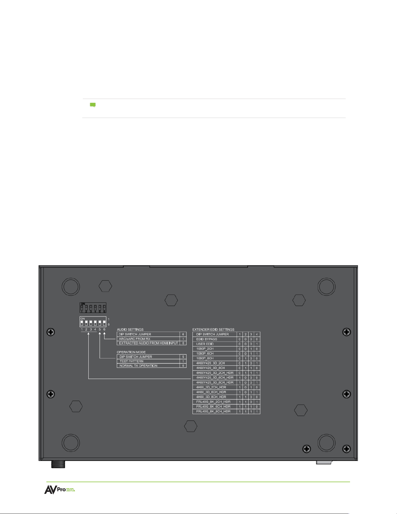
EDID Management (Transmitter)
The transmitter (AC-EXO-X-PLUS-T) comes equipped with dipswitches located underneath the device for
selecting an EDID.
Dipswitches 1, 2, 3, and 4 correspond to the EDID jumper settings. Flip the dipswitches up (“on” or “1”) or
down (“off” or “0”) to select the corresponding EDID setting.
AC-EXO-X-PLUS-T Bottom Panel
AC-EXO-X-PLUS-KIT User
Manual
Page 18 of
23
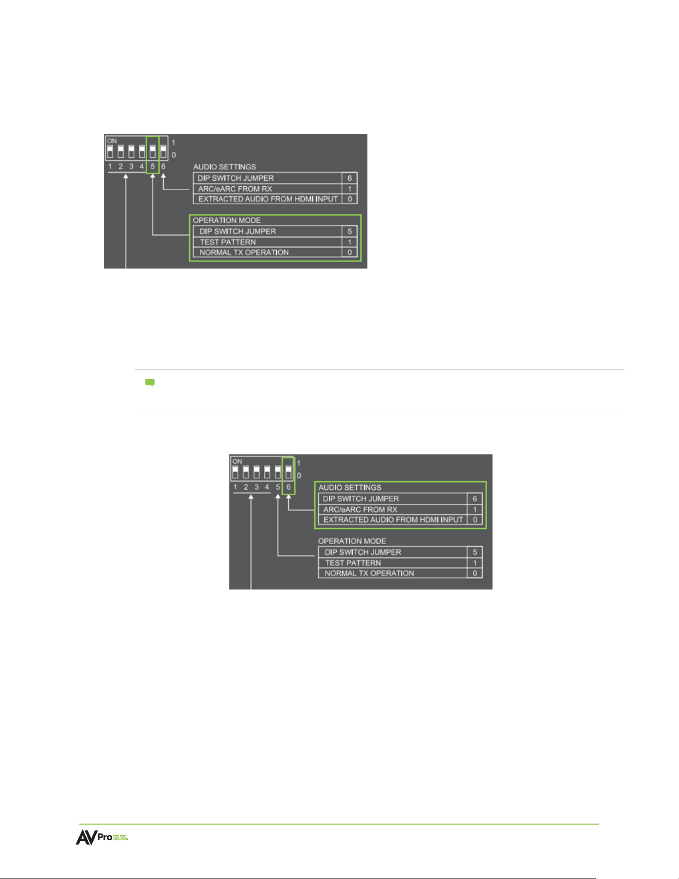
Test Pattern
The transmitter can generate a color bar test pattern using dipswitch 5. Flip the dipswitch up (“on” or “1”)
to generate a color bar test pattern.
Audio Extraction/Extension
This feature extracts up to 8-channel audio from the source device and sends it to a separate
amplifier or AVR. The transmitter can be changed using a dipswitch on the button of the unit,
while the receiver can be changed using a front panel toggle switch.
Note:
You can extract audio at the Transmitter via the TOSLINK OUT port. The source of the
audio can either be HDMI (ARC/eARC) or you can input via the TOSLINK IN port on the
Receiver.
Transmitter Audio Settings
Extract Audio from HDMI Input (TOSLINK Output Only): The default for the
transmitter is to source audio from the HDMI IN port. The dipswitch position of 0 will
source the audio from the Transmitters HDMI input port.
Extract Audio from Receiver (TOSLINK and ARC/eARC HDMI Output): If the audio is
coming from the Receiver’s HDMI OUT ARC/eARC port set the dip switch position to 1
on the Transmitter. If the Receiver does not have an active ARC/eARC or digital audio
input, no audio will be played.

AC-EXO-X-PLUS-KIT User
Manual
Page 19 of
23
Receiver Audio Settings
Send Audio to Transmitter from Receiver’s HDMI ARC/eARC: If the audio is coming
from the Receiver’s HDMI OUT ARC/eARC port, set the slider switch to the ARC/eARC
(TV) position. An active ARC/eARC signal must be received by the HDMI Output
connection from the display’s ARC/eARC port.
Extract Audio from Receiver (TOSLINK and ARC/eARC HDMI Output): If the audio is
coming from the Receiver’s TOSLINK port, set the slider switch to the TOS position.
Note:
Both connected devices must support ARC/eARC. Ensure the port you are
connecting to is labeled ARC/eARC. Some devices may require ARC/eARC
functionality set to enabled. It is recommended to check the device’s user manual
to verify the ARC/eARC function is on or enabled.
Ethernet Extension
Ethernet usage is very straightforward, it is designed for driving network communication over
the fiber connection. The purpose of these ports is to act as a “hub”, meaning if one port is
plugged into a router then the other port on either the Transmitter or Receiver will have
access to the network.
Other examples of Ethernet usage include:
•
Supplying a hardwired Ethernet connection to video zones for on-device streaming
and/or local gaming devices and players.
•
Providing server-based content from a server to a remote display.
•
Supplying a zone with a hardwired Ethernet connection for a Wi-fi access point in
remote zones.
The ports are always active so long as one of the Ethernet ports on either the Transmitter or
Receiver is connected to the network—the other port will also have access.
Ethernet Indicator Lights
Left LED (Amber)
Indicates a stable Ethernet connection is made. This light should always be a solid amber.
Right LED (Green)
Indicates there is online activity. This light flashes randomly as data is transmitted. If it is not
illuminating, then there is no data coming through or the router may need to be reset.

AC-EXO-X-PLUS-KIT User
Manual
Page 20 of
23
Command List
For RS-232 control, use a null modem serial cable adapter and set the serial communications to:
Baud: 57600, no parity, 8 data bits, 1 stop bit, no handshaking. Add a carriage return (Enter key) after
each command when using direct commands. All commands start with the System Address prefix A00.
Command:
Action:
H
Help
STA
Show global system status
SET ADDR xx
Set System Address to xx {xx=[00-99](00=single)}
GET ADDR
Get System Address
GET IN1 SIG STA
Get Input1 Signal Status
GET OUT1 TP CAB LEN
Get HDBT Output1 CableLength(Unit: m)

AC-EXO-X-PLUS-KIT User
Manual
Page 21 of
23
Troubleshooting
•
Verify Power – Check the POWER light is solid blue on the front panel of both the transmitter and
receiver. This indicates there is power connected and present on the devices.
Note :
The AC-EXO-X-PLUS-KIT must be powered from both units for complete operation. See
Power Connections
•
Verify Connections – Check that all cables are properly connected and can support 48 Gbps.
Check the LINK light is solid blue on the front panel of both the transmitter and receiver.
•
Issues with One Output – Swap HDMI outputs to see if issue follows. Try copying EDID from the
display. See
EDID Management
•
Issues with Legacy HDMI Device when Scaling – Ensure the legacy device supports the input
source’s frame rate. Ensure Variable Refresh Rate is disabled and supports meta-data.
•
Not Passing Video – Use the built-in test pattern on the transmitter.
•
IR Issues – Verify correct connections and settings.
Note
:
Use the provided IR cables included with the device. Visible flashing IR emitters or other
third-party IR cable functionality is not guaranteed.
Maintenance
To ensure reliable operation of these devices as well as protecting the safety of any person using or
handling these devices while powered, please observe the following instructions:
•
Use the power supplies provided by the manufacturer. If an alternate power supply is required,
check the voltage and polarity for sufficient power to supply the device it is connected to.
•
Do not operate the devices outside of the specified temperature and humidity range given in the
technical specifications.
•
Ensure there is adequate ventilation to allow the devices to operate efficiently.
•
Repair of the devices and other equipment should only be carried out by qualified professionals
as these devices contain sensitive components that may be damaged by any mistreatment.
•
Only use the devices in a dry environment. Do not allow any liquids or harmful chemicals to come
into contact with these devices.
•
Clean the devices with only a soft, dry cloth. Never use alcohol, paint thinner, or benzene.
Damage
Requiring Service
The devices should be serviced by qualified service personnel if:
•
The DC power supply cord or AC adapter has been damaged
•
Objects or liquids have gotten into the devices
•
The devices do not operate normally as intended or exhibit a marked change in performance
•
The devices have been dropped the housing has been damaged

AC-EXO-X-PLUS-KIT User
Manual
Page 22 of
23
Support
Should you experience any problems while using the devices, first refer to the Troubleshooting section of
this user manual before contacting AVPro Edge Technical Support. When calling, the following
information should be provided:
•
Device name and model number
•
Device serial number
•
Details of the issue and any conditions under which the issue is occurring
Warranty
The Basics
AVPro Edge warranties its products that are purchased from all authorized AVPro Edge resellers or
direct purchases. Products are guaranteed to be free from manufacturing defects and are of sound
physical and electronic condition.
AVPro Edge has developed a warranty that anyone can get behind. We really wanted to take all the
“red tape” out of a warranty and just make it simple. Our 10 Year No BS Warranty hinges on 3
elements:
•
If you are having trouble, call us. We will attempt to troubleshoot your issue over the phone.
•
If it’s broken, we will replace it in advance on our dime and we’ll also cover the return shipping.
Repair is an option too, but it’s YOUR call.
•
We know you know what you are doing. We will not make you go through unnecessary steps
to troubleshoot an extender…
Coverage Details
AVPro Edge will replace or repair (at customer choice) the defective product. If the product is out of
stock or on backorder it can either be replaced with a comparable product of equal value/feature set
(if available) or repaired.
Your warranty begins at receipt of product (as confirmed by shipping firm tracking). If tracking
information is unavailable for any reason, the warranty will commence 30 days ARO (After Receipt of
Order). The warranty coverage continues for 10 years.
Red Tape
AVPro Edge is not responsible for untraceable purchases or those that were made outside of an
authorized channel.
If we conclude that a product or serial number has been tampered with as identified by warranty seal
or physical examination, the warranty will be void. Additionally, excessive physical damage (beyond
normal wear & tear) the warranty may be voided or prorated based on the extent of the damage as
examined by an AVPro Edge representative.
Damage caused by “acts of God” are not covered. They can include natural disasters, power surges,
storms, earthquakes, tornadoes, sink holes, typhoons, tidal waves, hurricanes, or any other
uncontrollable event related to nature.
Damage caused by incorrect installation will not be covered. Incorrect power supply, inadequate
cooling, improper cabling, inadequate protection, and static discharge are examples of this.

AC-EXO-X-PLUS-KIT User
Manual
Page 23 of
23
Products installed or sold by a third party to AVPro Edge will be serviced by the authorized AVPro
Edge reseller. Accessories (IR cables, RS-232, power supplies, etc.) are not included in the warranty.
We will make acceptable efforts to source and supply replacements for defective accessories at a
discounted rate as needed.
Obtaining an RMA
Dealers, resellers, and installers can request an RMA from an AVPro Edge Technical Support
Representative or their Sales Engineer. You may also email [email protected] or fill out the
general contact form at avproedge.com/contact. End users may not request an RMA directly from
AVPro Edge and will be referred back to their dealer, reseller, or installer.
Shipping
For USA (not including Alaska and Hawaii), shipping is covered on advanced replacements for FedEx
Ground (some expressed exceptions may apply). Defective product return shipping is covered by
AVPro Edge using an emailed return label. Items must be returned within 30 days of receipt of the
replacement product, after 30 days, the customer will be billed. Other return shipping methods will not
be covered.
For international (including Alaska and Hawaii), return shipping costs will be the responsibility of the
returnee. Once the unit is scanned for return shipping, AVPro Edge will ship the new unit for
replacement.
Limitation on Liability
The maximum liability of AVPro Global Holdings LLC under this limited warranty shall not exceed the
actual purchase price paid for the product. AVPro Global Holdings LLC is not responsible for direct,
special, incidental, or consequential damages resulting from any breach of warranty or condition, or
under any other legal theory to the maximum extent permitted by law. Taxes, Duties, VAT, and freight
forwarding service charges are not covered or paid for by this warranty.
Obsolescence or incompatibility with newly invented technologies (after manufacture of product) is
not covered by this warranty. Obsolescence is defined as:
“Peripherals are rendered obsolete when current technology does not support product repair or re-
manufacture. Obsolete products cannot be re-manufactured because advanced technologies
supersede original product manufacturer capabilities. Because of performance, price and
functionality issues, product redevelopment is not an option.”
Discontinued or out-of-production items will be credited at fair market value towards a current
product of equal or comparable capabilities and cost. Fair market value is determined by AVPro
Edge.
Exclusive
Remedy
To the maximum extent permitted by law, this limited warranty and the remedies set forth above are
exclusive and in lieu of all other warranties, remedies, and conditions, whether oral or written, express
or implied. To the maximum extent permitted by law, AVPro Global Holdings LLC specifically disclaims
any and all implied warranties, including, without limitation, warranties of merchantability and fitness
for a particular purpose. If AVPro Global Holdings LLC cannot lawfully disclaim or exclude implied
warranties under applicable law, then all implied warranties covering this product, including
warranties of merchantability and fitness for a particular purpose, shall apply to this product as
provided under applicable law.
This warranty supersedes all other warranties, remedies, and conditions, whether oral or written,
express or implied.