ACDUAL
AUTOMOTIVE REFRIGERANT MANAGEMENT CENTER
Recover, Recycle, Evacuate & Recharge A/C Systems
In Passenger Vehicles & Light Trucks
For Use With R-134a and R-1234yf Refrigerants
OWNER’S MANUAL (English)
TO BE OPERATED BY QUALIFIED PERSONNEL ONLY
UL1963 EEI, CSA C22.2 120 DEI, SAE J3030


3
CONTENTS
General Safety Instructions ...........................................4
Product Registration......................................................5
Agency Approvals, Standards, Patents
........................ 5
Overview
........................................................................5
Key Features / Benets
.................................................6
Optional Accessories
.................................................... 6
Specications
................................................................7
ACDUAL Machine ........................................................ 7
Vacuum Pump ............................................................ 7
Refrigerant Scale ........................................................ 7
30 Lb Recovery Tank ...................................................8
50 Lb Recovery Tank (Optional) ...................................8
Refrigerant Cylinder Heater Blanket (Optional) ...........8
Machine Layout
............................................................ 9
Quick Start Guide
.........................................................11
Overview (Primary Touch Screen Keys)
..................... 12
Home ....................................................................... 12
Touch Keys & Information Icons .............................. 12
Print Key, Help Menu ............................................... 13
Machine Upkeep ...................................................... 14
Setup functions ........................................................14
Maintenance Menu ................................................... 14
Hybrid Vehicle Key .................................................... 15
Setup
...........................................................................16
Set Language ........................................................... 16
Set Units of Measure ............................................... 16
Set Tank & Refrigerant Weights ............................... 17
Job Tracker .............................................................. 18
Wireless Device Setup .............................................. 19
Set Date Or Time ....................................................... 20
Online Registration/Warranty .................................. 21
Shop Information ...................................................... 22
Select SAE Or Global Standards ............................... 23
Operation ..................................................................24
Refrigerant Recovery & Refrigerant Identier .......... 24
A/C System Evacuation ............................................ 26
Refrigerant Charging ............................................... 27
Full Cycle ................................................................. 29
Refrigerant Tank Rell ............................................. 30
Maintenance
...............................................................32
Filter/Dryer Change ................................................. 32
Vacuum Pump Oil Change (Frequency) .................... 34
Oil Change Procedure ...............................................34
Pro-Set® Premium Vacuum Pump Oil ......................34
Refrigerant Change .................................................. 35
Refrigerant Charging Scale ..................................... 37
Pressure Transducer ................................................ 38
Tare Pressure Transducer .........................................38
Calibrate Pressure Transducer ..................................39
Automatic Air Purge ................................................. 40
Diagnostics of Valves, Controls, Scale ..................... 41
Software Upgrade ..................................................... 42
Touch Screen Display Calibration ............................. 42
Car System Health Mode
............................................ 44
Corded Temperature Probe (Included Accessory) ........ 45
A/C Database For North American Vehicles
.............. 46
Flush Refrigerant Hoses
.............................................47
Job Tracker
.................................................................47
APPENDIX
Touchscreen Icon Library
............................................ 48
ACDUAL Error Codes, Identier Codes
........................50
Replace Parts
.............................................................. 50
Warranty
......................................................................51
A/C Database End-User License Agreement
..............52

4
GENERAL SAFETY INSTRUCTIONS
Only qualied service personnel should operate this machine. Most states, countries, etc... may require the user to be
licensed. Please check with your local government agency.
DANGER – This unit’s recovery tank contains liquid refrigerant. Overlling of a recovery tank may cause a violent explosion
resulting in severe injury or even death. Do not disable the overll safety features. Always make sure the correct
tank is on the scale.
DANGER – Only use the specied recovery tanks provided with this unit. See your distributor for replacement tanks.
DANGER – Avoid breathing refrigerant vapors and lubricant vapor or mist. Breathing high concentration levels may cause
heart arrhythmia, loss of consciousness, or even cause suffocation.
DANGER – Electrical shock hazard!!!! Always disconnect power source when servicing this equipment.
DANGER – DO NOT USE COMPRESSED AIR TO PRESSURE TEST OR LEAK TEST THE ACDUAL UNIT OR VEHICLE AIR
CONDITIONING SYSTEM. Mixtures of air and refrigerant are combustible at elevated pressures. These mixtures
are potentially dangerous and may result in re or explosion causing personal injury or property damage.
CAUTION – All hoses may contain liquid refrigerant under pressure. Contact with refrigerant may cause frostbite or
other related injuries. Wear proper personal protective equipment such as safety goggles and gloves. When
disconnecting any hose, please use extreme caution.
CAUTION – Exposure to refrigerant vapors may irritate eyes, nose, throat, and skin. Please read the manufacturers Material
Safety Data Sheet for further safety information on refrigerants and lubricants.
CAUTION – To reduce the risk of re, avoid the use of extension cords thinner than NO. 16 awg. (1,5mm2). The following table
references extension cord wire size vs. maximum length:
EXTENSION CORD (Imperial) EXTENSION CORD (Metric)
Gauge (awg) Length (Ft)
16 10
14 20
12 25
Gauge (mm2) Length (m)
1.5 3
2.5 6.1
4 7.6
CAUTION – Do not use this equipment in the vicinity of spilled or open containers of gasoline or other ammable substances.
Make certain that all safety devices are functioning properly before operating the equipment.
CAUTION – This equipment should be used in locations with mechanical ventilation that provides as least 4 air changes per hour.
CAUTION – RISK OF INJURY, the equipment should only be operated by certied personnel.
CAUTION – Use only CPS certied hose assemblies on this unit. The hose assemblies are made to proper length, contain
shut-offs where required and have direct affect on the proper operation of this equipment.
CAUTION – R-1234yf is a Class III highly ammable refrigerant. Use in well ventilated areas. Minimize leakage from the unit.
Periodically check ACDUAL machine for leaks.
1. The ACDUAL will alert the user should a high pressure condition exist on the outlet side of the compressor.
2. When such a condition is detected, the compressor will turn OFF and won’t restart until the high pressure condition is remedied.
3. If this occurs, check to ensure that Tank Valves and Hose Ball Valves running to the tank and lters are OPEN.
4. If all valves are open, contact CPS Technical Support to determine the cause of the alarm.
High Pressure Alert

5
GENERAL SAFETY INSTRUCTIONS (Cont’d)
PRODUCT REGISTRATION
To register this ACDUAL Refrigerant Management Machine for the 1-2-3 Product Warranty, please visit
www.cpsproducts.com/hvac-warranty-registration/. Please contact us, if you have any technical issues during
registration of this machine.
You may also register this ACDUAL Machine by using the touch screen (See Page 21).
1. The ACDUAL Series’ 30lb internal storage tank is designed to contain a maximum of 20.96 Lbs (9.52 Kg) of
refrigerant.
2. If this amount is exceeded, the user will be alerted and system operations will be halted.
3. Before normal operation can continue, the overll condition must be remedied by moving refrigerant from the tank
to another storage tank or into a vehicle AC system. The charge function may be used to transfer internally stored
refrigerant to an external storage facility.
Tank Overll Limit
AGENCY APPROVALS, STANDARDS, PATENTS
UL 1963 EEI Issued: 2013/10/11 Ed: 4 Refrigerant Recovery/Recycling Equipment
CSA C22.2 120 DEI Issued: 2013/03/01 Ed: 4 Refrigeration Equipment (R2018)
SAE J3030 Issued: July 1, 2015. Automotive Refrigerant Recovery/Recycling/Recharging Equipment Intended for
Use with Both R-1234yf and R-134a.
• This machine is covered under US Patent 8,082,750.
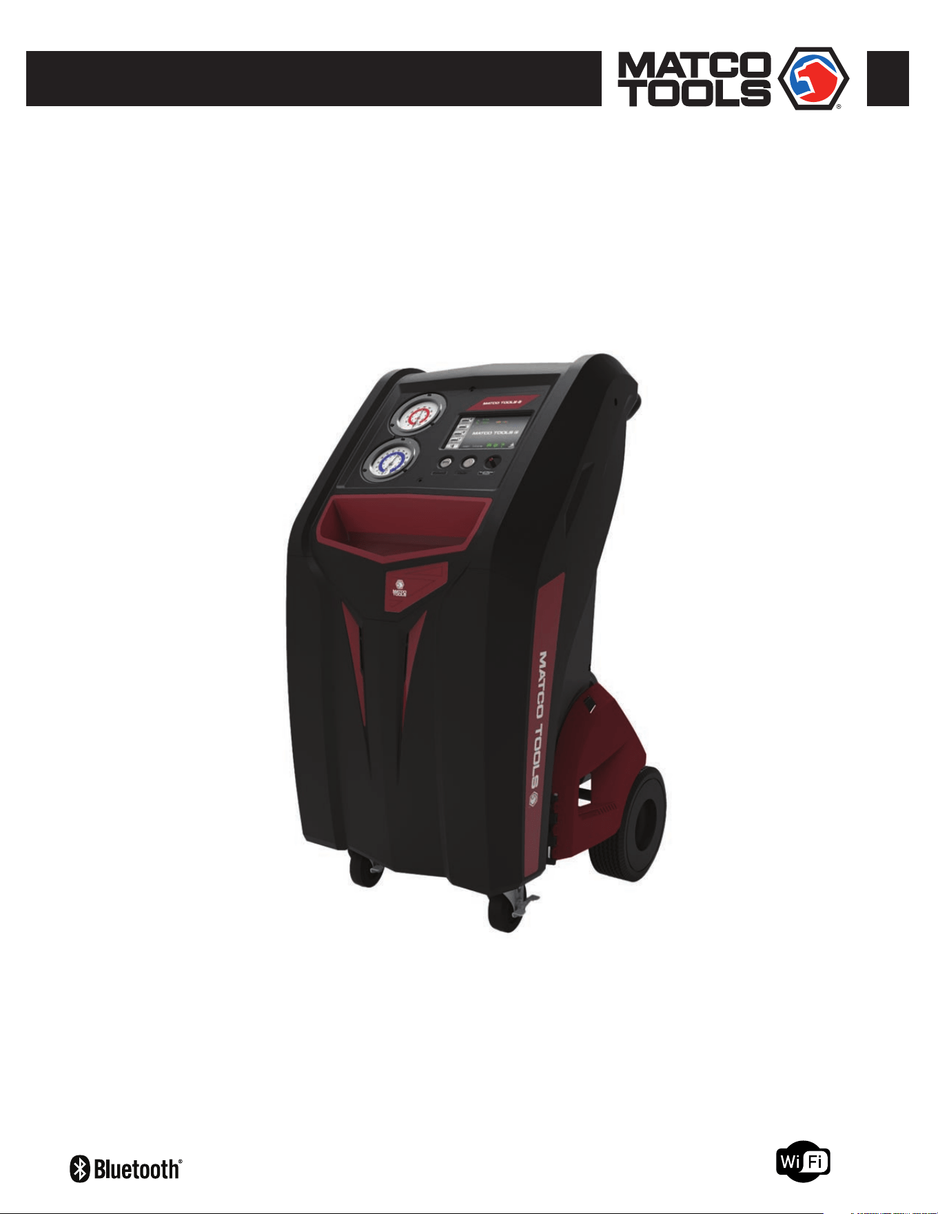
OVERVIEW
The ACDUAL Refrigerant Management Center is for use with both R-134a and R-1234yf refrigerants and has been designed
for automotive technicians to easily Recover, Recycle, Evacuate and Recharge air conditioning systems in passenger vehicles
and light trucks. It features a seven inch, color touch screen display, a 30 Lb refrigerant tank, an oil-less compressor and
motorized ball valves.

6
Optional Accessories
• Heater Blanket (#AR27XHB115) – During colder weather, this CPS 120V AC accessory can be applied to the refrigerant
tank to speed up charging, which eliminates the need to run a vehicle’s AC system.
• TACI100 CarSmart AC Inspector – Includes 2 probes for measuring or data logging temperature, humidity,
dew point, etc., inside of, or around a vehicle.
• 50 Lb Refrigerant Tank – Available from CPS as individual tanks, or in pallet quantities (see page 8).
• Dust Cover (#MXXC) – Fits any ACDUAL machine.
Not Included (Shop Must Purchase)
• Refrigerants (R-134a, R-1234yf)
• Refrigerant oil/dye injection system.
Features Benets
7” Color Display, With Touch-Screen Icon
User-friendly icons allow fast, easy selection of Recovery,
Evacuation, Charge, Full Cycle and Tank Rell functions, or Setup
and Maintenance Menus.
Vehicle A/C System Database
ACDUAL machines include a database of refrigerants and
refrigerant oil for most vehicles sold in North America since 1994.
Low and High Side “Barrier” Service Hoses &
Couplings
The included barrier hoses and couplings minimize the loss of
expensive refrigerant, which can also harm the atmosphere.
Filter/Dryer
The installed lter-drier lters the R-1234yf refrigerant inside
the vehicle’s A/C system, and absorbs any system contaminants
which can reduce compressor life.
Motorized Ball Valves
Automatically open or close for a selected charge, recovery or
evacuation routine.
Temperature Probe Accessory
ACDUAL machines include a corded probe (#TMX2P) for
measuring temperature in AC vents.
1 Lb (454 Gm) Check Weight For accurately calibrating the installed refrigerant charging scale.
30 Lb Refrigerant Tank
The DOT certied tank is designed to safely recover, charge and
transport refrigerant used with ACDUAL machine. Available in
single cylinders or in pallet quantities (see below).
Bluetooth Low Energy (BLE) Capable
ACDUAL machines can be used with the CPS
®
“CarSmart AC
Inspector” wireless accessory (#TACI100) to log temperature,
humidity, dew point and other diagnostic data inside of, or around
a vehicle.
Wi-Fi Capable
ACDUAL Machines can be connected to other Wi-Fi devices
or printers and job reports can be e-mailed directly from the
machine.
Industry Leading Warranty (2-2-3)
Two Year Parts and Labor Warranty, Three Year Compressor
Warranty.
KEY FEATURES/BENEFITS

7
SPECIFICATIONS
Power 115V 60Hz
Compressor 2/3 HP Twin Cylinder Oil-less
Gauges 3.5” Low side, 30 in/Hg to 250 psi; High Side, 0 to 600 psi
Hoses 10 Ft. (3.0 m), Barrier Type
Refrigerant For Use With R-1234yfyf Only
ASHRAE Refrigerant Code A1
Maximum Recovery Rate Up To 1 Lb (0.453 kg) per minute
Storage Tank 1 x 30 lb DOT tank (specications on page 8)
Display 7” Touch Screen with 256 color graphical display
Construction
Sheet metal frame with molded plastic panels. 1 piece handlebar, 4” front casters and 10” foam-lled rear tires for
exceptional maneuverability
Operating Temperature Range 50°F to 122°F (10°C to 50°C)
Operating Humidity Range 0% to 95% (Non-Condensing)
Dimensions (H x W x D) 43.6” x 22.6” x 28.9” (1.1 x 0.57 x 0.28 m)
Weight (Without Packaging) Gross Weight: 208 Lbs (With Packaging)
Warranty (1-2-3)
See Page 51
Stage 2
Maximum Free Air Displacement 2 CFM at 60 Hz / 48l/m @ 50 Hz
Motor Size (HP), RPM @ 50/60Hz 1/3 HP (@1440 RPM/50 Hz Or 1720 RPM/60 Hz)
Voltage, Watts, Amps 110~120VAC Or 220VAC @50/60 Hz
Ignition Proof Construction Meets ANSI 12.12.1
Ultimate Vacuum 10 Microns
Refrigerant Class A1, A2
Operating Temperature Range 32°F to 125°F (0°C to 52°C)
Storage Temperature Range 32 F to 104 F (0 C to 40 C)
Pro-Set® Vacuum Pump Oil Capacity 11 oz (330 ml)
Intake Fittings 1/4” & 3/8” SAE Male, ACME 1/2”
High Side Gauge (Analog) 0 ~ 550 psi, (38 bar ~ bar), 3792 ~ kPa
Low Side Gauge (Analog) 0 ~ 350 psi, (0 ~ 24 bar), 0 ~ 2400 kPa)
Motor Thermally Protected Yes
INSTALLED VACUUM PUMP SPECIFICATIONS
ACDUAL OVERALL SPECIFICATIONS
Tare (Empty) Weight Mode Yes
Units (Weight) Readout lb & oz, or kg & gm
Weight Accuracy 0.015% of Reading [or ± 0.25 oz (10 g) whichever >]
Display Resolution (Increments) 0.25 Oz (10 g)
Platform Dimensions 8.75˝ x 8.75˝ (22.3 x 22.3 cm)
Overload Protection Mechanical (Internal Overload Stop)
Calibrated To NIST Standards Yes
Declaration Of Conformity EN 61326-1:2013, CISPR 11:2009/A1:2010
INSTALLED REFRIGERANT SCALE SPECIFICATIONS
8
SPECIFICATIONS (Cont’d)
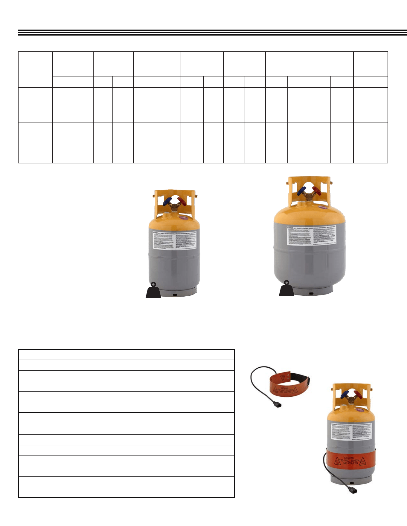
CPS REFRIGERANT TANK SPECIFICATIONS (Industry Standard)
Weight Of
Empty Tank
Tank Water
Capacity
Max. Refrigerant
Weight (80% Of
Water Capacity)
Total Weight
(Tank &
Refrigerant)
Tank Foot Ring
Diameter
Tank Outside
Diameter
Tank Height
Max.
Pressure
Rating
lb kg lb kg lb kg lb kg in mm in mm in mm psig (bar)
CRX430T
30 Lb
(13.60 kg)
Included
17.5 7.9 26.2* 11.9* 20.96* 9.52* 38.46 17.42 7.8 198.1 9.5 241.3 18.1 459.7 400 (27.57)
Optional
Accessory:
CRX400T
50 Lb
(22.7 kg)
28.3 12.8 47.4 21.5 37.92* 17.2* 66.22 30.0 8 203.2 12.5 317.5 19.75 501.7 400 (27.57)
*Maximum weight of refrigerant that should be recovered
REFRIGERANT RECOVERY TANKS
• DOT Certied for refrigerant storage
• Refrigerant compatible sealant used
on all mechanical connection points
• Auxiliary port for optional overll
sensor
• Liquid and Vapor UL listed
• Y-valve powder coated for maximum
rust protection
• 1/4˝ SAE Male ttings
CRX430T (FACTORY INSTALLED ON ACDUAL
MACHINES)
CRX430TB
(40/PALLET-OPTIONAL ORDER QTY)
30 lb
CRX400T (OPTIONAL SIZE TANK)
CRX400TB
(24/PALLET-OPTIONAL ORDER QTY)
50 lb
REFRIGERANT CYLINDER HEATER BLANKET (OPTIONAL ACCESSORY)
SPECIFICATIONS
AR27XHB115-1
Voltage (Hz) 120 VAC (50/60 Hz)
Watts 340 W
Amps 2.8
For Cylinder Sizes From 8˝ (20 cm) to 14˝ (35 cm) Diameter Tanks
Control (Overheat Protection) Automatic Thermal Cutoff (Encapsulated Thermostat)
Minimum Surface Temperature Of Tank 115°F (46°C)
Maximum Thermostat Temperature 130°F (55°C)
Power Cord Length 20˝ (0.50 m)
Adjustable Velcro Strap Max Length 19˝ (0.48 m)
Heater Blanket Width 3˝ (76 mm)
Heater Blanket Length 24˝ (.60 m)
Heater Blanket Color Dark Orange
Electrical Connection Type IEC320 C15 Female Connector
HEATER BLANKET
AR27XHB115 (
120V)
SHOWN: HEATER BLANKET
APPLIED TO TANK
9
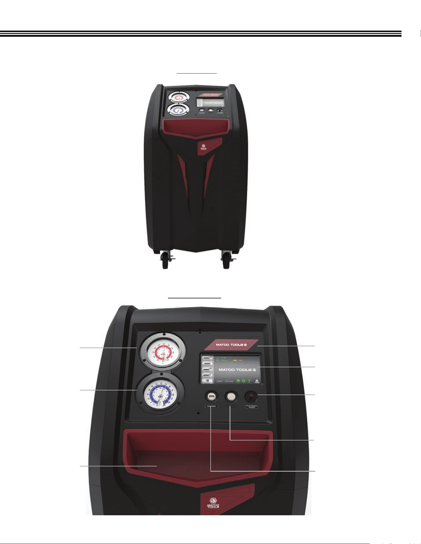
MACHINE LAYOUT
FRONT VIEW
CONTROL PANEL
Storage Tray
For Small Tools
Or Fittings
3.5” High Side
Gauge (Analog)
3.5” Low Side
Gauge (Analog)
7” Color Touch Screen
LCD Display
Machine Brand ID
RCA Port (For Temperature
Probe #TMX2P Accessory
(Included)
Power (On/Off)
Button
USB Port
10
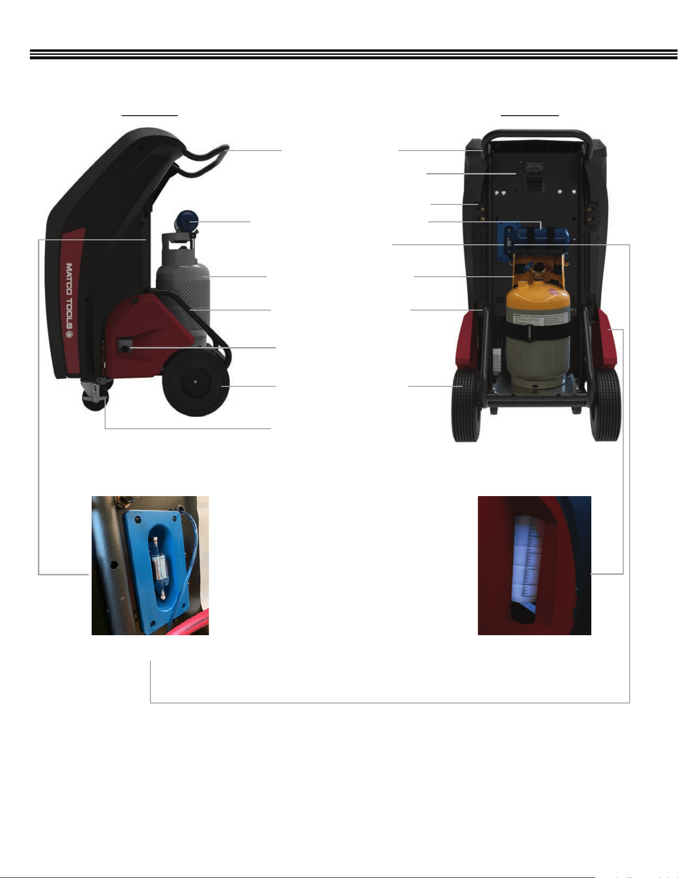
MACHINE LAYOUT (Cont’d)
REAR VIEWSIDE VIEW
4” Swivel Locking Caster
Brake, Polyurethane Tread
10” Rear Rubber Wheels
(Foam Filled)
Vacuum Pump Oil Level
(Sight Glass)
Handle Bar (1 Piece)
SD Card Port (Access
North American A/C Database)
Left & Right Side Hose Connections
Replaceable Refrigerant Filter/Dryer
Refrigerant Identier
30 Lb Refrigerant Recovery
(Internal) Tank
One Piece Welded Frame
Refrigerant Oil Recovery
Bottle
Refrigerant Identier
11
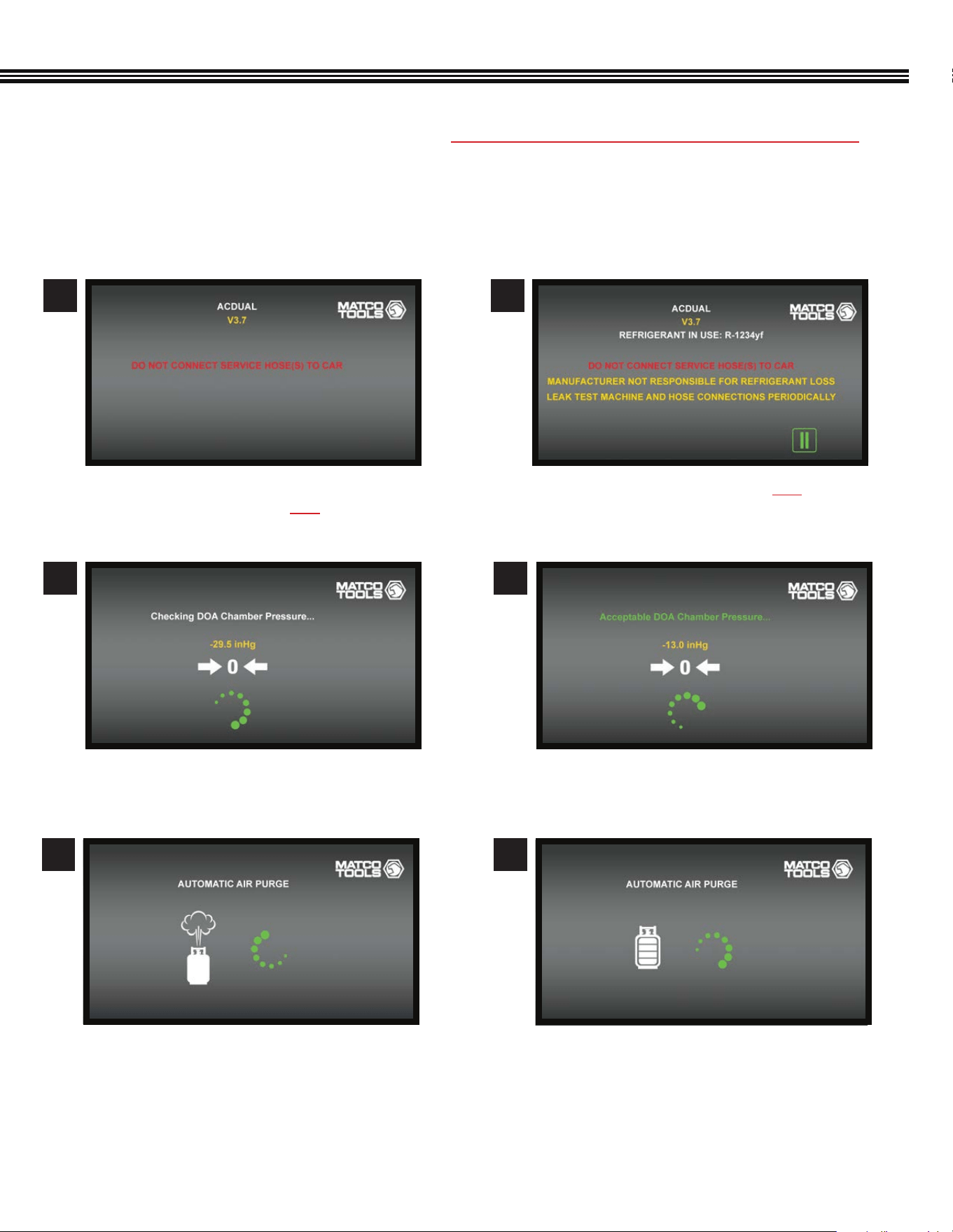
1. Remove the protective packaging between the storage tank and the scale.
2. NOTE: BEFORE TURNING THE ACDUAL MACHINE ON, ENSURE THERE ARE NO HOSES CONNECTED TO VEHICLE
3. The Vacuum Pump on ACDUAL Machines contains Vacuum Pump Oil (factory lled). Check the “Sight Glass” on the
Vacuum Pump to ensure the oil level is between the MAX and MIN lines.
4. Plug the ACDUAL Power Cord into a proper power source.
5. On the front control panel, push the POWER BUTTON. A Blue Light will then turn ON.
6. Machine will go through the following internal status check (not all screens are shown)
a. Initial Start-Up Screen (shows Version #)
b. SERVICE HOSES SHOULD NOT BE CONNECTED
TO CAR AT THIS TIME.
a. Checking DOA Chamber (for oil separation)
Pressure.
a. ENSURE SERVICE HOSES ARE NOT CONNECTED
TO VEHICLE.
7
9
8
a. Acceptable Distillation Chamber Pressure.
10
QUICK START GUIDE
a. Automatic Air Purge is now complete.
b. Home Screen (will reappear once Air Purge
has completed).
c. Connect service hoses to the machine and
install the include Oil Recovery Bottle.
d. Machine can now be operated by using the
color Touch Screen.
a. Automatic Air Purge (if needed).
1211
12
Pg 42
Pg 13
Pg 14
Pg 13
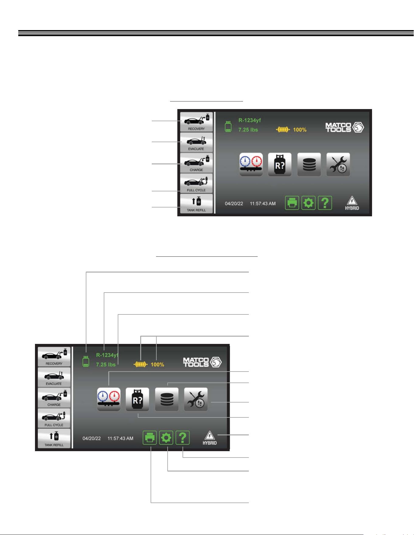
Weight Of Refrigerant In
Tank (4 Segment Icon)
Filter Dryer Life (4 Segment Icon)
Weight Of Refrigerant In Tank
Refrigerant Type In Tank
Refrigerant Identication Key
Pg 46Job Tracker Key
Pg 44A/C Data Base & End User
License Agreement Key
Car System Health Mode Key
Pg 15Hybrid Vehicle Key
Help Menu Key
Machine Upkeep Key
- Setup Function
- Maintenance Menu
Print Key
OVERVIEW (Primary Touch Screen Keys)
1. Refrigerant Recovery Key
Pg 24
Pg 26
Pg 27
Pg 29
Pg 30
2. A/C System Evacuation Key
3. Refrigerant Charge Key
5 Selectable Functions
Touch Keys & Information Icons
HOME SCREEN
5. Refrigerant Tank Rell Key
4. Full Cycle Key (Recovery,
Evacuate & Recharge)
This ACDUAL machine features a 7” (17.8 cm), color, touch-screen LCD display from which all machine functions or
settings can be accessed.
13
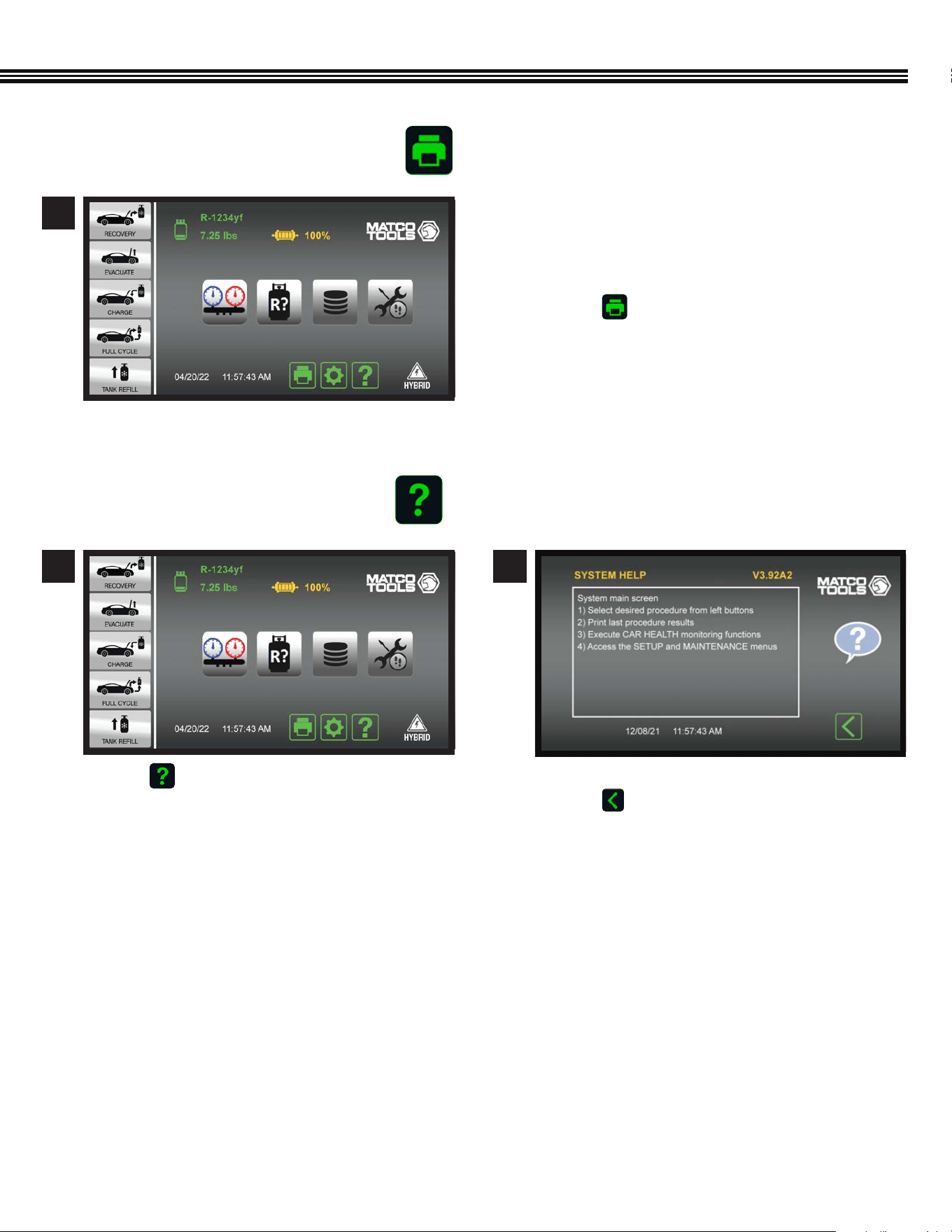
PRINT KEY
HELP MENU
a. Use the ACDUAL’s Bluetooth Low Energy or
Wi-Fi functions to connect to a wireless printer.
The Bluetooth range is generally 30 ft, while
Wi-Fi is generally 150 ft (both direct line of sight).
b. Touch to receive a printed copy showing
results of the LAST function performed.
1
a. Touch to enter the HELP MENU. a. Firmware Version shown at UPPER RIGHT.
b. Touch to return to Home Screen.
1 2
Home Screen
Home Screen Help Screen
OVERVIEW (Primary Touch Screen Keys, Cont’d)
14
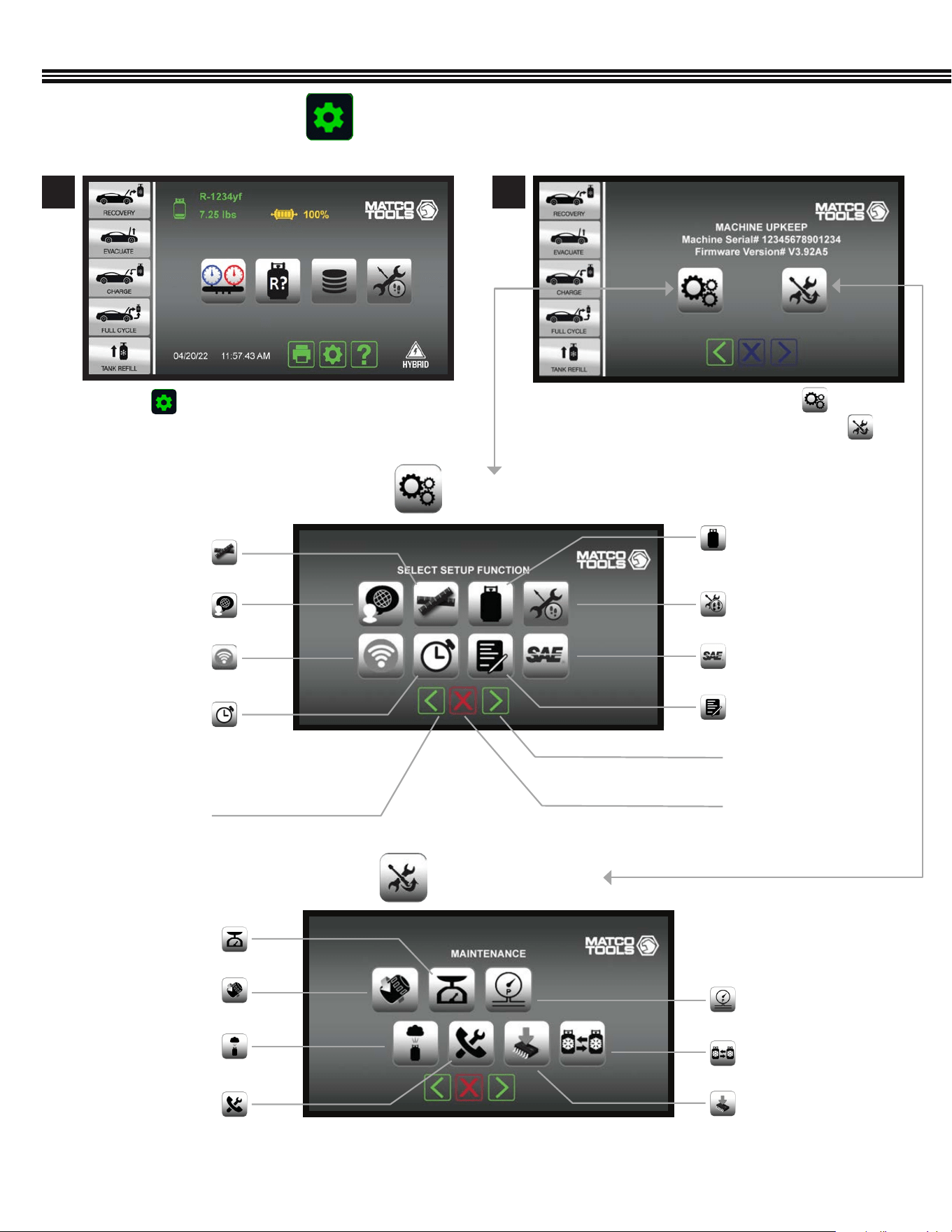
a. To enter the SETUP FUNCTION, touch
b. Or to enter the MAINTENANCE MENU, touch
a. Touch to access the MACHINE UPKEEP Screen
Shop Information
Next Screen/Enter
Previous Screen
Cancel
Units Of Measure
Tank Weight Or
Refrigerant Weight
Set Time Or Date
Wireless Setup
Language
SETUP FUNCTIONS
Home Screen Machine Upkeep Screen
1 2
Job Tracker
SAE (Or Global Standards)
Filter Change
Automatic Air Purge
Valves & Controls
Pressure Transducer
Change Tanks
Software Upgrade
Scale Maintenance
Modes
MAINTENANCE MENU
OVERVIEW (Primary Touch Screen Keys, Cont’d)
MACHINE UPKEEP (2 Functions)
15
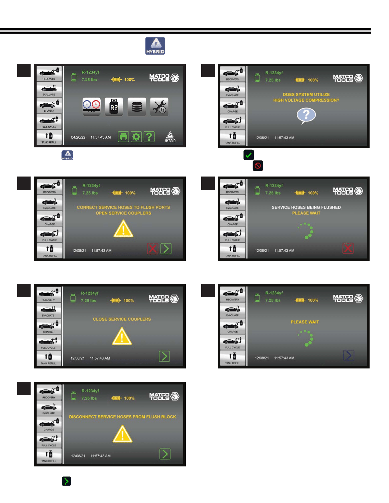
HYBRID VEHICLE KEY
a. Touch if the vehicle is Hybrid so service
hoses are automatically ushed.
a. Connect service hoses to FLUSH PORTS.
b. OPEN SERVICE COUPLERS
a. DISCONNECT SERVICE HOSES from Flush Block
b. Touch to move to Home Screen.
a. CLOSE SERVICE COUPLERS
a. Touch if vehicle uses a HIGH VOLTAGE COMPRESSOR
b. Or touch to return to HOME SCREEN
1
Home Screen
3
2
4
5
7
6
OVERVIEW (Primary Touch Screen Keys, Cont’d)
16
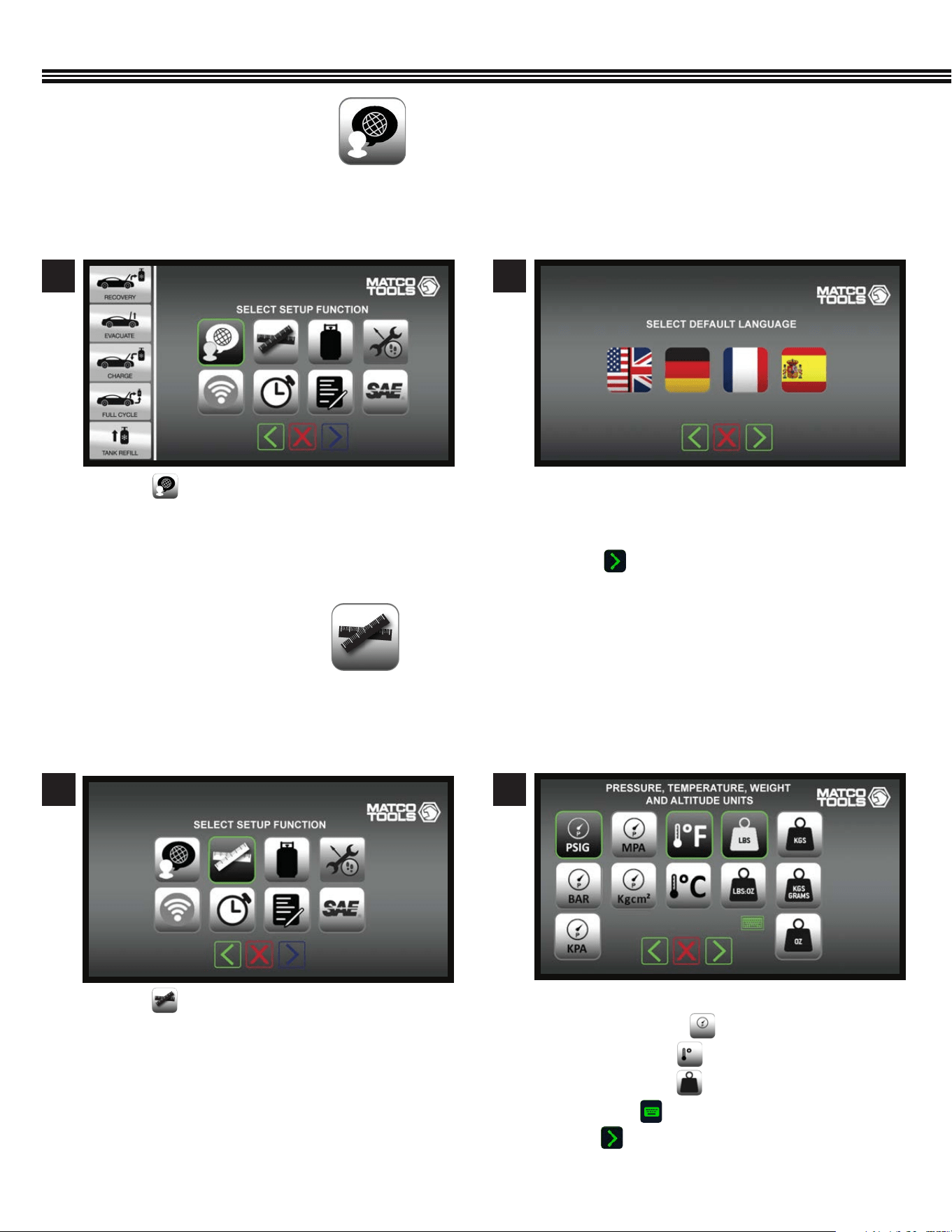
a. Touch keys to select default Units Of Measure:
• Pressure Units
• Temperature
• Weight Units
• Altitude (enter value with keyboard).
b. Touch to enter data and move to next screen.
SETUP
Select Pressure, Temperature, Weight, AltitudeSetup Function Screen
a. Touch to select Units Of Measure.
21
SET UNITS OF MEASURE
(Not All Screens Are Shown)
a. Touch a key that corresponds to the screen
language you prefer: English / Spanish / French /
German
b. Touch to enter selected language.
a. Touch to veiw languages to work in.
Use this function to set up the ACDUAL so that it displays Pressure, Temperature, Weight and Altitude in SAE or Metric units of
measure that you want to work with.
ACDUAL Machines have an English language default setting. To change the default FROM English TO either German, French or
Spanish, use the following instructions.
21
Setup Function Screen Select Default Language
SET LANGUAGE
(Not All Screens Are Shown)
17
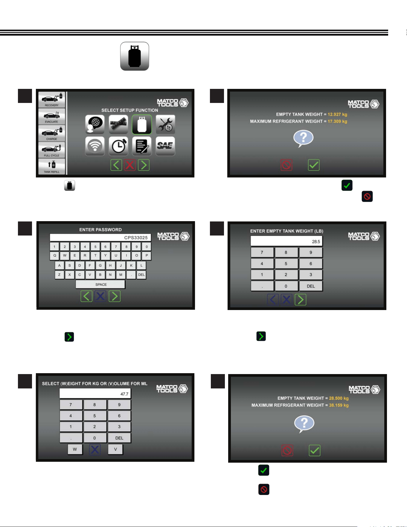
a. Touch if values are correct, and move to next
screen.
b. Touch if further changes needed.
SETUP (Cont’d)
Setup Function Screen
Enter Password (Before Changing Weights) Conrm (Or Change) Tank Weight
Conrm (Or Change) Weights*
(*For 30 Lb Tank Shown)
SET TANK & REFRIGERANT WEIGHTS
(Not All Screens Are Shown)
a. Touch and to move to next screen. a. If weights shown are correct, touch
b. If weights shown must be changed, touch
a. Use keypad to enter shop password (example only
shown above).
b. Touch to enter password and move to the next
screen.
a. Enter EMPTY TANK WEIGHT. (example only shown
above)
b. Touch to enter tank weight and move
to the next screen.
1 2
3 4
a. Touch “W” for WEIGHT, OR “V” for VOLUME.
5 6
Enter Tank Water Capacity Conrm Or Change Refrigerant/Tank Weights
18
SETUP (Cont’d)
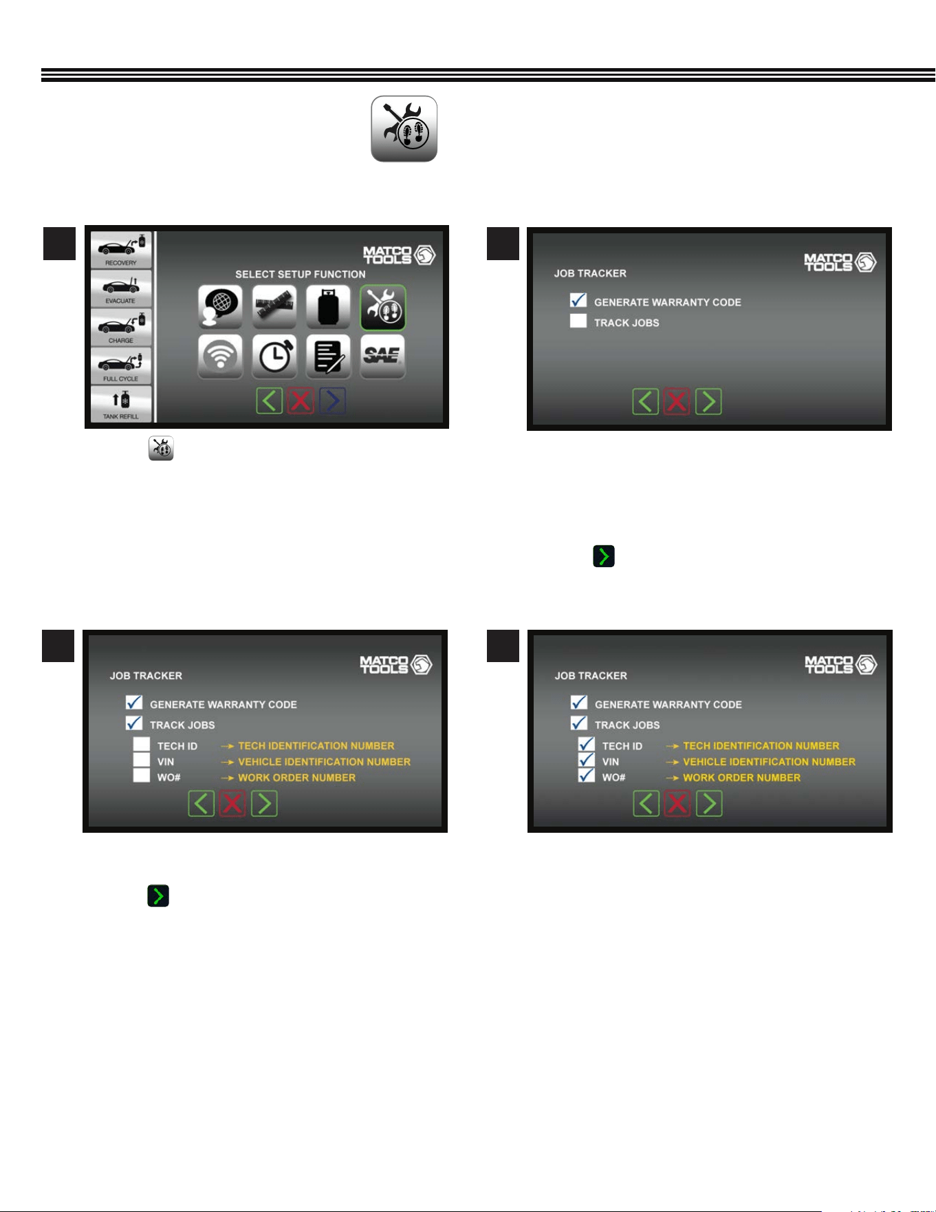
a. Touch .
a. Touch any white box to check or uncheck which
items to appear on a report.
b. Touch to enter selections and go to next
screen.
a. Warranty Code – Touch white box to have ACDUAL
machine generate an encrypted warranty code for
manufacturer’s vehicle being serviced.
b. Track Jobs- Touch white box to have Job Data
appear (in next screen).
c. Touch to enter selections and move to next
screen.
1
3 4
2
JOB TRACKER
(Not All Screens Are Shown)
Setup Function Screen
Job Tracker Screen Job Tracker Screen
Job Tracker Screen
19
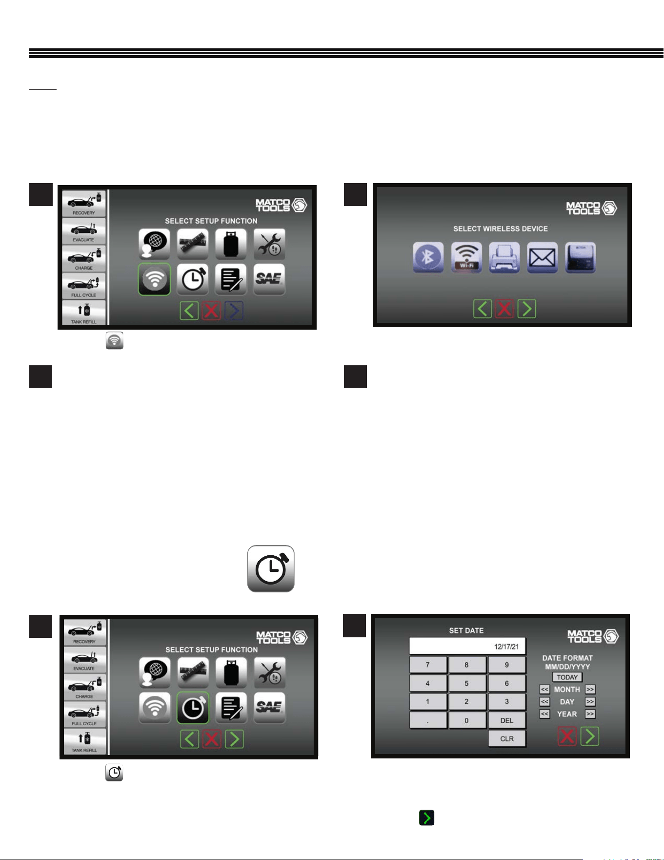
WIRELESS DEVICE SETUP
(Not All Screens Are Shown)
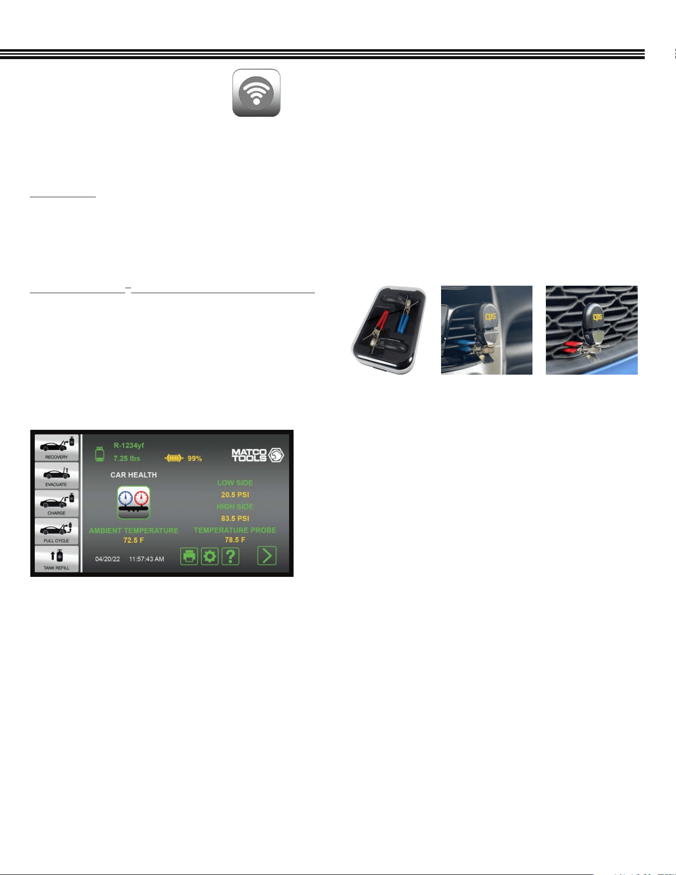
The ACDUAL features Bluetooth Low Energy and Wi-Fi capability for wireless connection to other wireless devices.
Bluetooth LE
Bluetooth Low Energy (Bluetooth LE, colloquially BLE, formerly marketed as Bluetooth Smart) is a wireless personal area
network technology designed and marketed by the Bluetooth Special Interest Group (Bluetooth SIG). BLE is independent of
classic Bluetooth and has no compatibility. Mobile operating systems including iOS, Android, Windows Phone and BlackBerry,
as well as macOS, Linux, Windows 8 and Windows 10, natively support Bluetooth Low Energy.
TACI100 CarSmart
®
A/C Inspector Temperature Probes
(an optional accessory from CPS Products) can be paired
via BLE to any of the ACDUAL machines. These 2 probes allow
technicians to data log temperature, feels like temperature,
humidity, dry and wet bulb, and dew point readings inside of,
or around passenger vehicles and light trucks over a preset
period of time.
Other BLE devices such as a thermal printer can be connected to the ACDUAL.
SETUP (Cont’d)
a. Ambient and Cabin Temperature values can be
viewed when in the Car Health Mode (shown).
Storage Case
Measure temperature or humidity at
2 locations simultaneously.
20
43
Bluetooth Low Energy (BLE) Devices
a. After the CPS brand CarSmart BLE devices have
been set up, they can be enabled/disabled by
touching a “checkbox” under the BT logo image.
b. When a BLE device is enabled, the system will
search for and connect to it when found and, when
a BLE device has been connected, the Bluetooth
icons will appear on the LCD touch screen.
Wi-Fi Devices
a. Select one or more of the desired Wi-Fi devices
(Wi-Fi Device, Printer, E-mail) to pair the ACDUAL.
b. After a Wi-Fi device has been set up, it can be
enabled/disabled by touching a “checkbox” under
the image of that device.
c. When a wireless device is enabled, the system
will search for and connect to it when found and,
when a Wi-Fi device has been connected, one or
more of the 4 icons (from #a above) will appear on
the touch screen.
SETUP (Cont’d)
a. Touch to set the Date or Time.
a. Touch keys to enter the current date (MM/DD/YYYY).
b. In next screen, touch keys to enter the time of day
(Hours, Minutes, Seconds).
c. Touch to enter data.
1
2
Set Date Or Time
SET DATE OR TIME
(Not All Screens Are Shown)
Setup Function Screen
BLE Or WiFi Device ScreenSetup Function Screen
a. Touch a key to connect that device to the ACDUAL
machine.
a. Touch to access wireless devices to be set up.
21
Wi-Fi
Wi-Fi is the wireless technology used to connect computers, tablets, smartphones and other devices to the internet,
and is the radio signal sent from a wireless router to a nearby device, which translates the signal into data you can see and
use. ACDUAL Machines can be connected to other Wi-Fi devices or printers. The ACDUAL also has the ability to mail job
reports by entering an e-mail address in the ACDUAL machine.
21
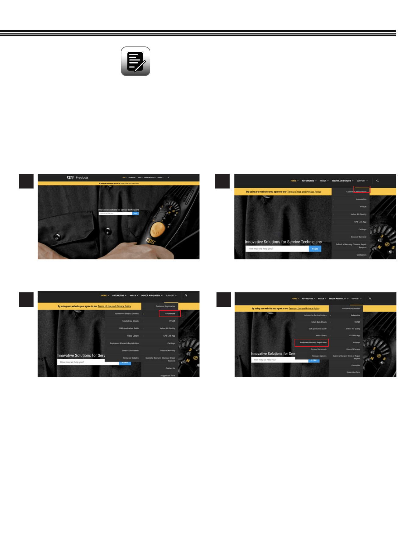
a. Select Equipment Warranty Registration. a. Enter information in the elds provided.
a. On the “Support” tab, select the “Automotive”
drop down.
3 4
1 2
The ACDUAL warranty is serviced by CPS
®
Products, Inc. If you register on-line, use the path provided to follow
the links in the CPS website.
Please use one of the following methods to register the ACDUAL Refrigerant Management Center for warranty:
A. On-Line Method: Visit “www.cpsproducts.com/hvac-warranty-registration/”
ONLINE WARRANTY / REGISTRATION
(Not All Screens Are Shown)
CPS Products Home Page (CPSPRODUCTS.COM)
SETUP (Cont’d)
22
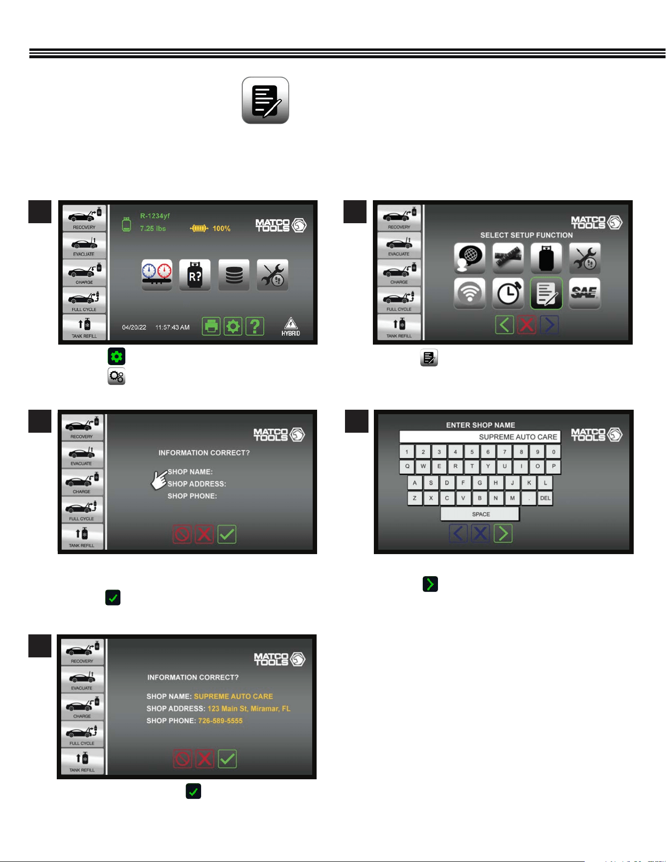
B. On-Screen Method:
Users may register an ACDUAL machine via the following “Onscreen” method:
a. Touch one of the the three lines where you want to
enter data.
b. Touch to reveal keypad.
a. If entries are OK, touch to move to next screen.
a. Touch . ,
b. Touch .
a. Touch and enter information by following the
prompts.
a. Use the keypad to enter data (example shown).
b. Touch to enter data and move to next screen.
3 4
5
Shop Information
Shop Information
Enter Business Name
1 2
Setup Function ScreenHome Screen
SHOP INFORMATION
(Not All Screens Are Shown)
SETUP (Cont’d)
23
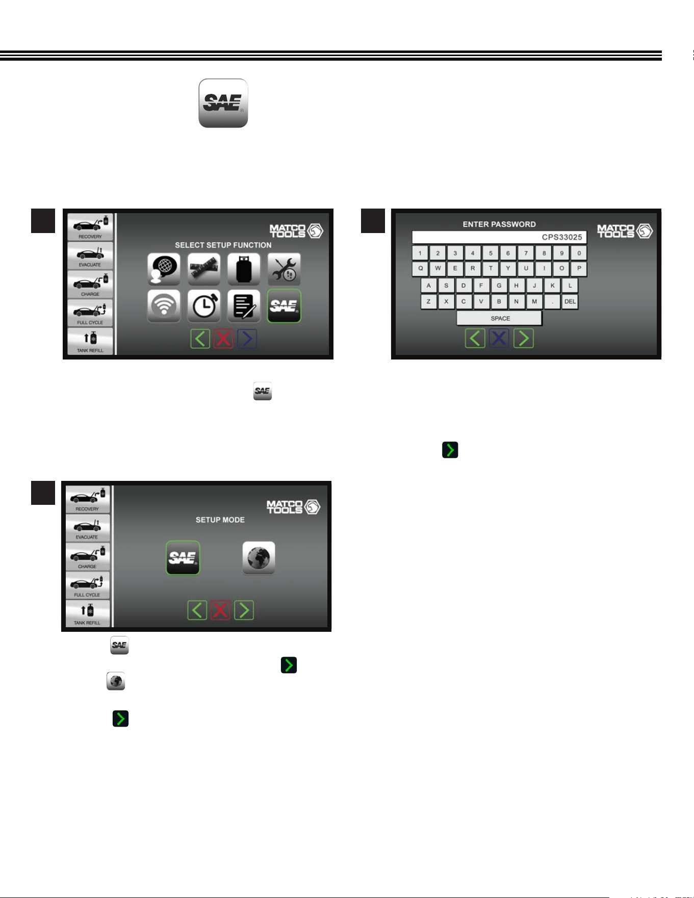
SELECT SAE OR GLOBAL STANDARDS
(Not All Screens Are Shown)
a. To change the factory default SAE Mode setting TO
International Mode, Touch the SAE key.
1
a. Enter password (example password shown.
Contact CPS Technical Support for password to
change to International Mode) that has been set
up for this machine.
b. Touch to enter password.
2
a. Touch so the ACDUAL machine operation
follows SAE J2788 standard, then touch OR,
b. Touch for the ACDUAL to follow
INTERNATIONAL STANDARDS.
C. Touch to enter selection and move to next
screen.
3
Setup Function Screen
Setup Function Screen
SETUP (Cont’d)
ACDUAL machines are shipped with a default SAE Mode setting (for the U.S. and most Canadian markets). Yet, some
Canadian and many global markets use the International setting.
24
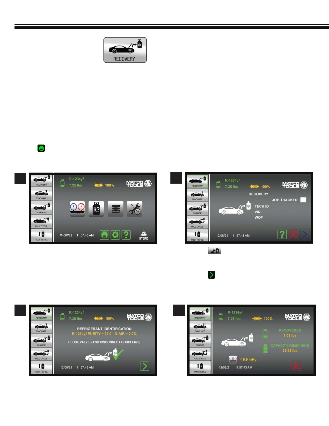
Home Screen Recovery Screen
REFRIGERANT RECOVERY
DO NOT CONNECT SERVICE HOSES TO REFRIGERANT SOURCE UNTIL INSTRUCTED TO DO SO.
The RECOVERY process pulls refrigerant into a distillation chamber which has a coil that is heated by compressor outlet gas.
This distills the refrigerant (turns it to gas) and separates liquids and debris from the refrigerant. Refrigerant then passes
through the distillation chamber and compressor and is condensed into a liquid before coming to rest in the internal (included
30 Lb) storage tank.
Refrigerant recovery automatically ends when the machine detects that the vehicle’s system is void of refrigerant.
The color display will show the amount (weight) of refrigerant that has been recovered. This information may be printed by
touching on the Home Screen.
REFRIGERANT RECOVERY
(Not All Screens Are Shown)
a. Before opening the vehicles’ A/C system for repair,
rst Recover & Recycle refrigerant from the A/C
system.
a. Touch .
b. Touch Job Tracker white box for Job Info to appear
on reports.
c. Touch to move to next screen to begin
the Refrigerant Identication process – follow
onscreen instructions to walk-thru process.
1
2
a. Once the Refrigerant Identication process is
complete, follow onscreen instructions to begin
the Refrigerant Recovery process.
3
a. Screen displays weight of refrigerant RECOVERED
and REMAINING TANK WEIGHT CAPACITY.
4
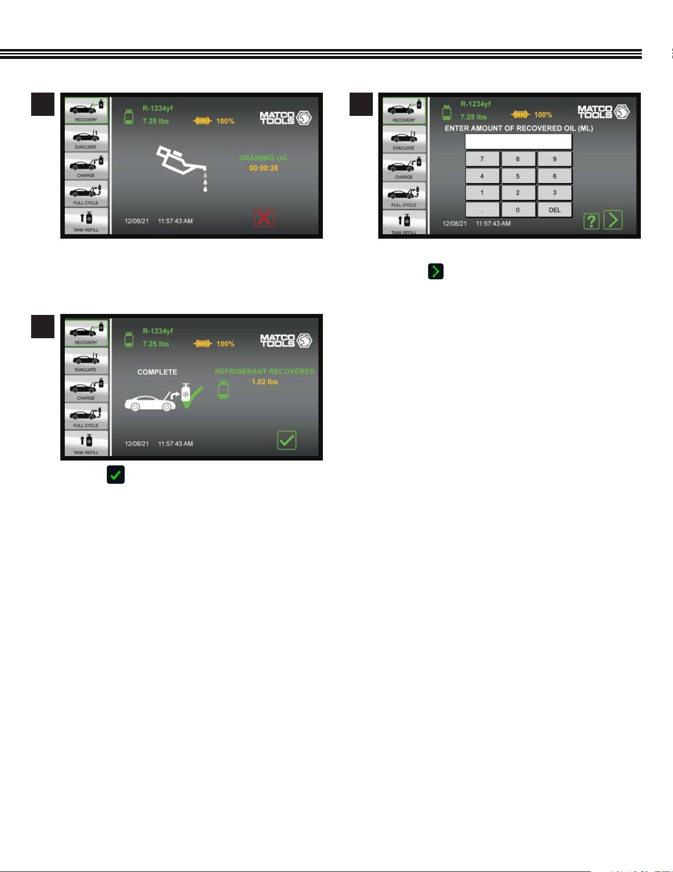
25
REFRIGERANT RECOVERY (Cont’d)
a. Refrigerant Oil draining (into the ACDUAL
machine’s included Oil Recovery Bottle).
b. Countdown timer shows remaining time.
a. Touch to return to Home Screen.
a. Use keypad to enter amount of recovered oil.
b. Touch to enter data and move to next screen.
5
7
6
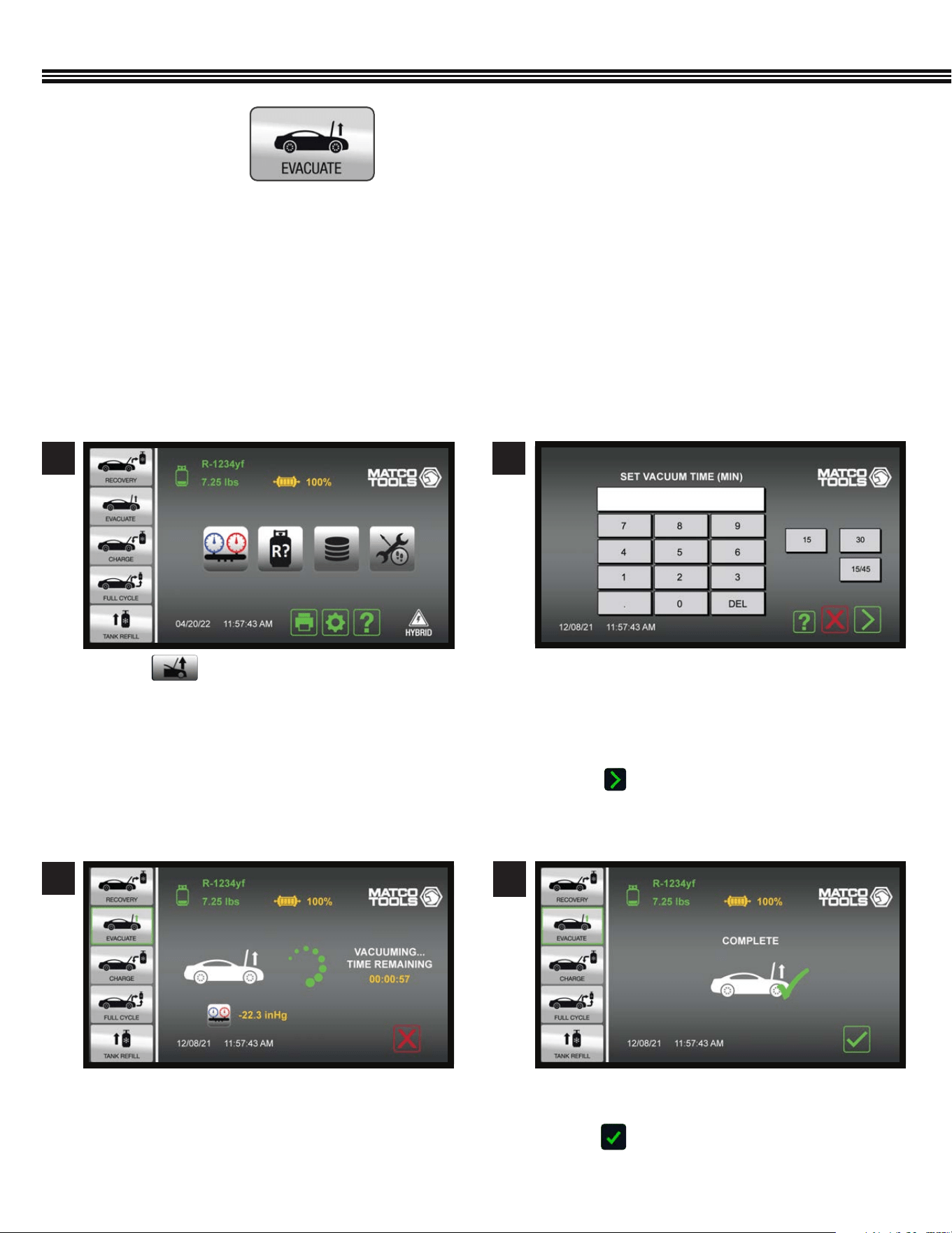
26
EVACUATION OF A/C SYSTEM
After all refrigerant has been recovered from the vehicle’s A/C system, and the system has been reassembled following any
repairs, the AC system must be evacuated.
Within a vehicle’s AC system, any moisture that is present can mix with oil to form “sludge”, while moisture mixed with
refrigerant forms hydrouoric and hydrochloric acids all of which can permanently damage a system. The ACDUAL Refrigerant
Management Center will “evacuate” (degas and dehydrate) an AC or refrigeration system prior to refrigerant charging.
A system that has been properly “evacuated” assures that non-condensable and moisture won’t later harm the
refrigerant or refrigerant oil in the system.
a. Touch for vehicle’s 2 CFM vacuum pump
to evacuate the A/C system.
1 2
A/C SYSTEM EVACUATION
(Not All Screens Are Shown)
a. A custom vacuum time may be entered, or one of
the preset 15 or 30 minute times may be selected.
b. If a vacuum time of 15 minutes or greater is
selected, evacuation will be followed by a 2
minute leak test (vacuum decay test).
c. Touch to enter evacuation time and move to
the next screen.
a. “Vacuum Time Remaining” will appear on the
display.
3
Select Run Time
Evacuation In Progress
a. When the specied Vacuum Time has expired, this
screen will appear.
b. Touch to return to Home Screen.
7
Vacuum Complete
4
Home Screen
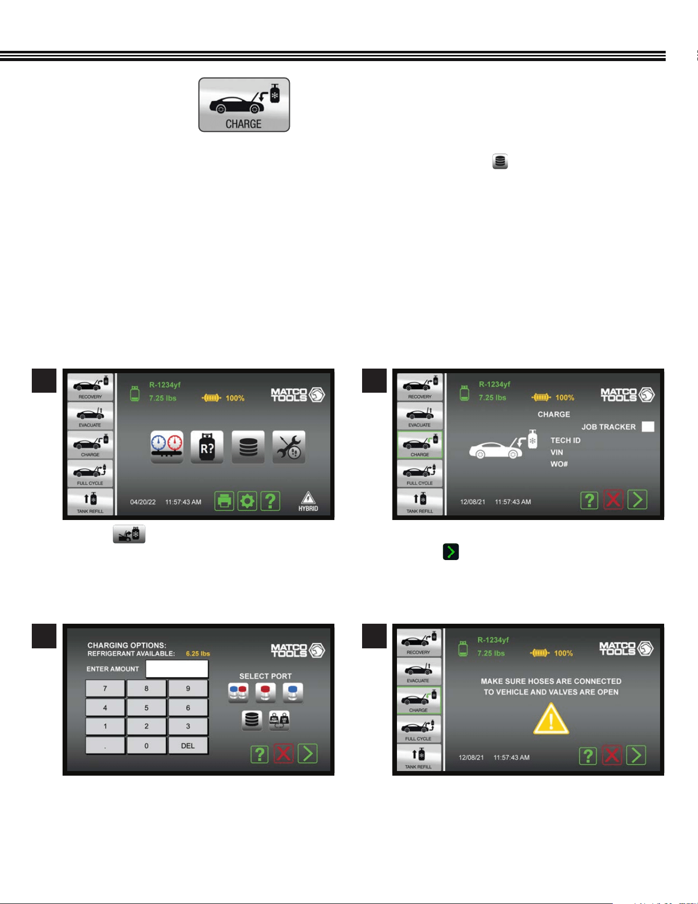
27
REFRIGERANT CHARGING
1. An A/C Database is integrated into the ACDUAL and, can be accessed by touching the key. This database will specify
the correct type and amount (weight) of refrigerant and refrigerant oil for vehicles sold in North America.
2. The charging sequence begins with a 10-minute vacuum leak test. This is an SAE requirement in SAE J2843 (R-1234yf)
systems only). If the system passes the vacuum leak test, the machine will charge the system to 15% of the
selected charge.
3. Use an electronic leak detector meeting SAE J2913 for R-1234yf to leak test the evaporator(s).
4. The ACDUAL will complete the remaining 85% of the charge.
5. Note; During cold conditions, a Heater Blanket (CPS optional accessory #AR27XHB115) may be wrapped around the
Recovery Tank to assist with charging. If the ACDUAL cannot complete a charge due to pressure equalization, it will notify
the
user to close the high side coupler and start the vehicle.
a. Touch .
a. Using the keypad, enter the desired charge
amount (refrigerant weight).
a. Enter: 1. Tech ID#, 2. Vehicle VIN#, 3. Work Order #.
b. Touch White Box for Job Tracker and proceed
to next screen.
a. Ensure hoses are connected to vehicle and hose
valves are OPEN.
1
3
2
4
REFRIGERANT CHARGING
(Not All Screens Are Shown)
Home Screen
28
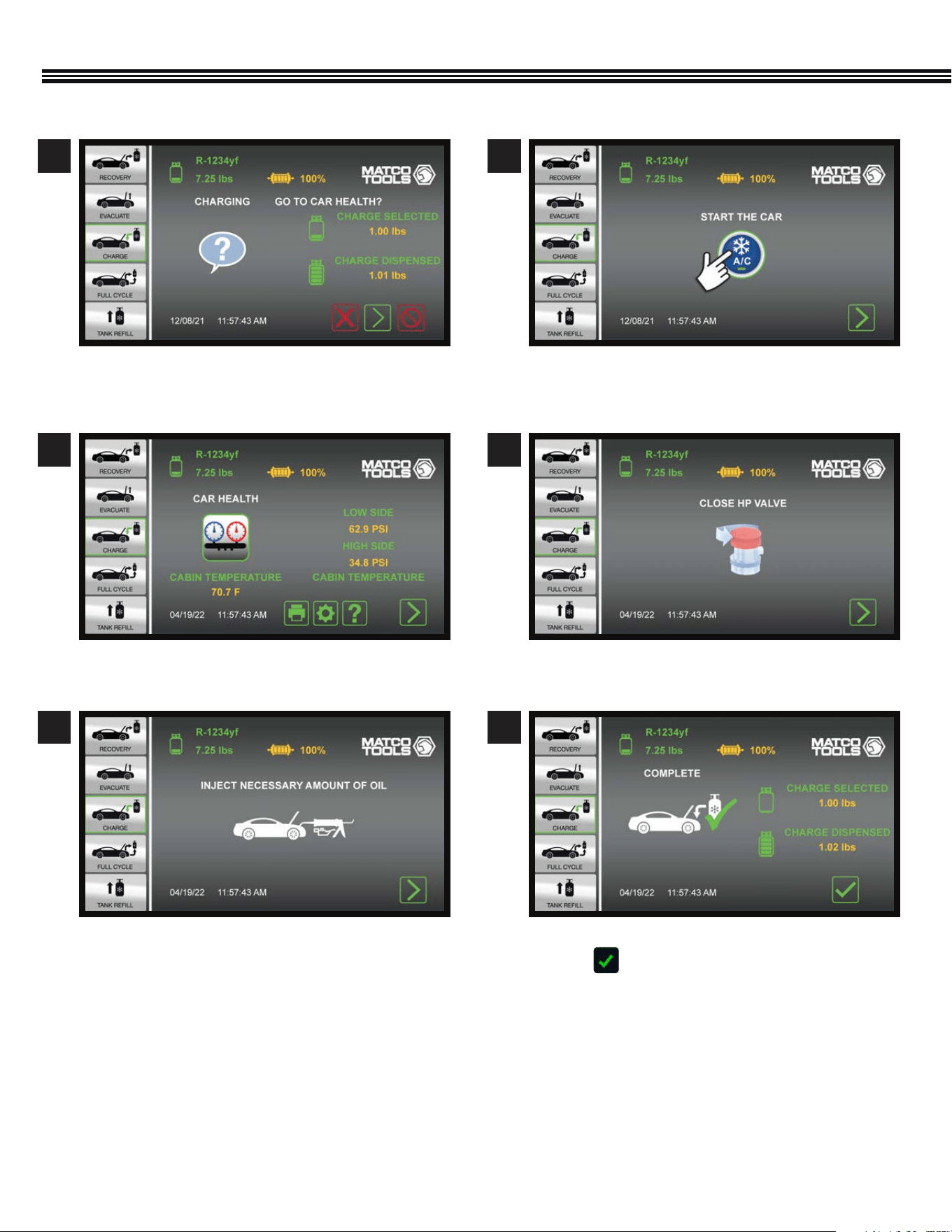
REFRIGERANT CHARGING (Cont’d)
a. Ensure hoses are connected to vehicle and hose
valves are OPEN.
a. Start the vehicle.
a. Inject mecessary amount of oil into vehicle.
a. Start the vehicle.
a. Close HP Valve, follow screen instructions to;
b. Close valves and disconnect coupler(s).
a. Final “Charge” Vs. “Dispensed” amounts shown.
b. Touch to proceed to the Home screen.
5
7
9
6
8
10
29
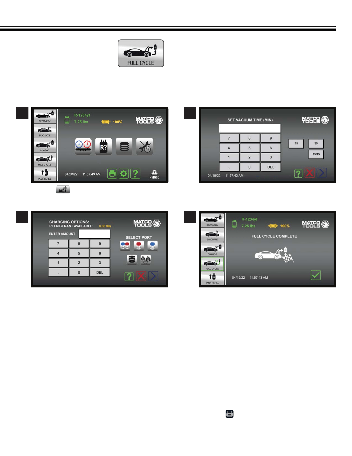
FULL CYCLE
Select “Full Cycle” on the Home Screen to Recover, Recycle, Vacuum, Leak Check (if desired) and Charge the
vehicle’s A/C system.
Full Cycle Process Outline
1. The display will prompt you to enter a vacuum time and a vehicle charge amount.
2. Once Full Cycle has been selected and started, the machine will proceed with the Refrigerant Identication process
followed by the Recovery process described in a previous section.
3. At the end of Recovery, the ACDUAL will automatically proceed to Vacuum and Leak Test (if the vacuum time
selected was greater than 10 minutes.)
4. Once the Vacuum process is complete, the desired charge amount will be installed in the vehicle.
5. The ACDUAL will then ask if you want to enter the Car Health Mode. Select this mode to check/print system
pressures and vent temperature.
6. If Car Health Mode is not selected, the ACDUAL will instruct how to transfer refrigerant contained in the
hoses into the vehicle’s AC system.
7. Final results of the Full Cycle process can be printed by touching the Print Key found at the bottom
of the “Home” screen.
FULL CYCLE
(Not All Screens Are Shown)
1 2
a. The display will prompt you to enter a vacuum
time and a vehicle charge amount.
a. Touch to go to FULLY CYCLE Function.
3
a. The display will prompt you to enter a vacuum
time and a vehicle charge amount.
4
a. Checkered ag icon displayed when Full Cycle
process is complete.
Home Screen Full Cycle Screen
30
FOLLOW DIRECTIONS ON SCREEN AND DO NOT OPEN COUPLE OR TANK VALVE UNTIL SCREEN SHOWS TO OPEN BOTH
It is suggested that at least 4.5 lbs (2 kg) of refrigerant be available in the storage tank to begin any operation. If less is
observed, choose this operation to add refrigerant to the internal tank. This operation transfers refrigerant in the liquid state to
the internal storage tank. The Refrigerant amount transferred in this mode is not counted toward the lter life.
CAUTION: If hoses were connected before instructed, the machine will post a warning and instruct that the couplers be
closed and the hoses removed. Not doing so will result in refrigerant loss (at the user’s expense).
FOLLOW DIRECTIONS ON SCREEN AND DO NOT OPEN COUPLER OR TANK VALVE UNTIL SCREEN SHOWS TO OPEN BOTH.
IF YOU FAIL TO OPEN TANK, START OVER.
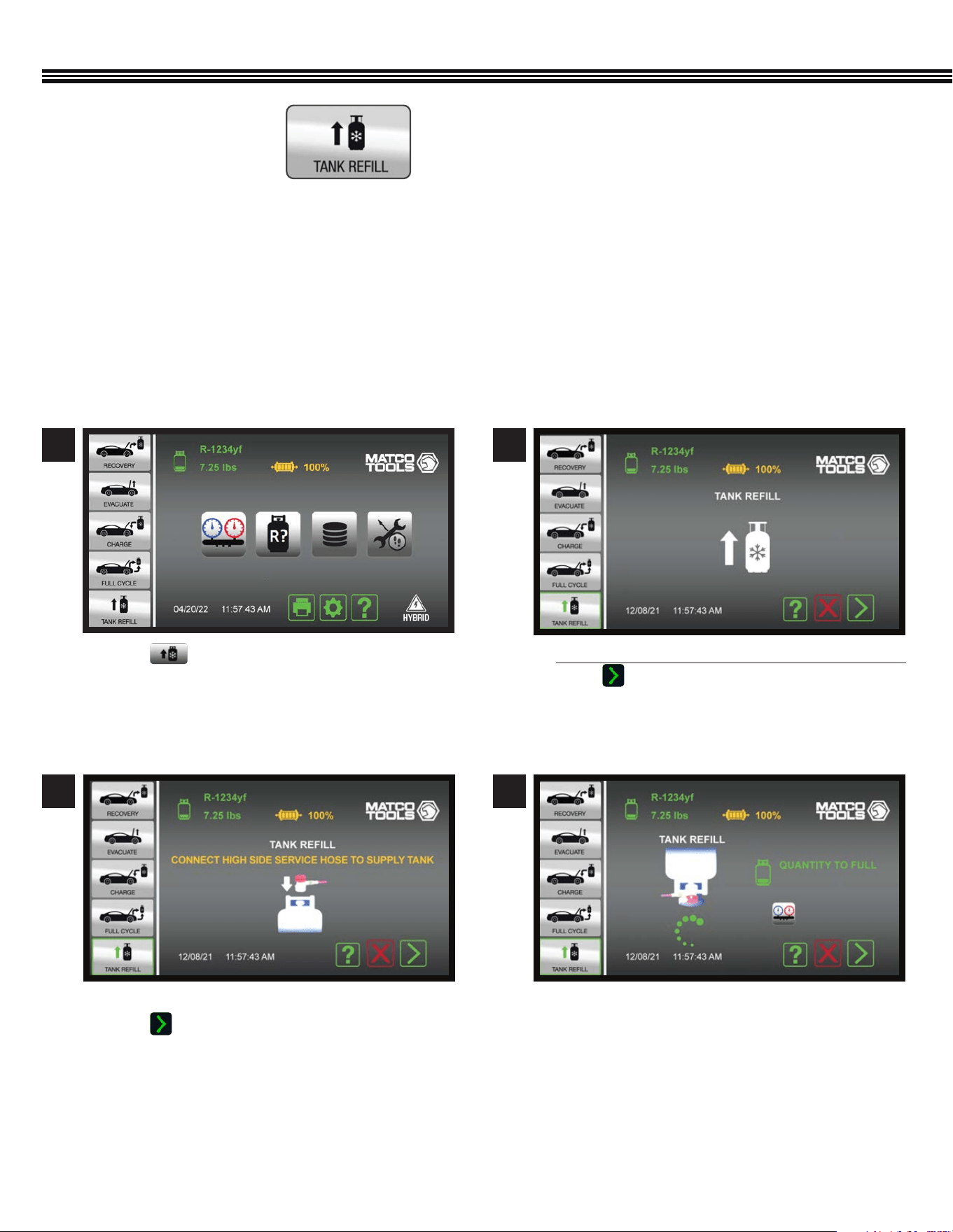
REFRIGERANT TANK REFILL
a. Touch to add refrigerant to the ACDUAL Tank.
FAILURE TO OPEN TANK VALVES WHEN INSTRUCTED
WILL RESULT IN HAVING TO START OVER FROM
BEGINNING
a. Connect High Side Service Hose to Supply Tank.
b. Touch and follow the on screen instructions.
a. Start with hoses disconnected and couplers closed.
b. Touch and follow the on screen instructions.
a. Invert the Supply Tank (source of refrigerant for
the ACDUAL tank) so that a liquid transfer can
occur.
1
3
2
4
REFRIGERANT TANK REFILL
(Not All Screens Are Shown)
Tank Rell
Tank Rell
Home Screen
Tank Rell
31
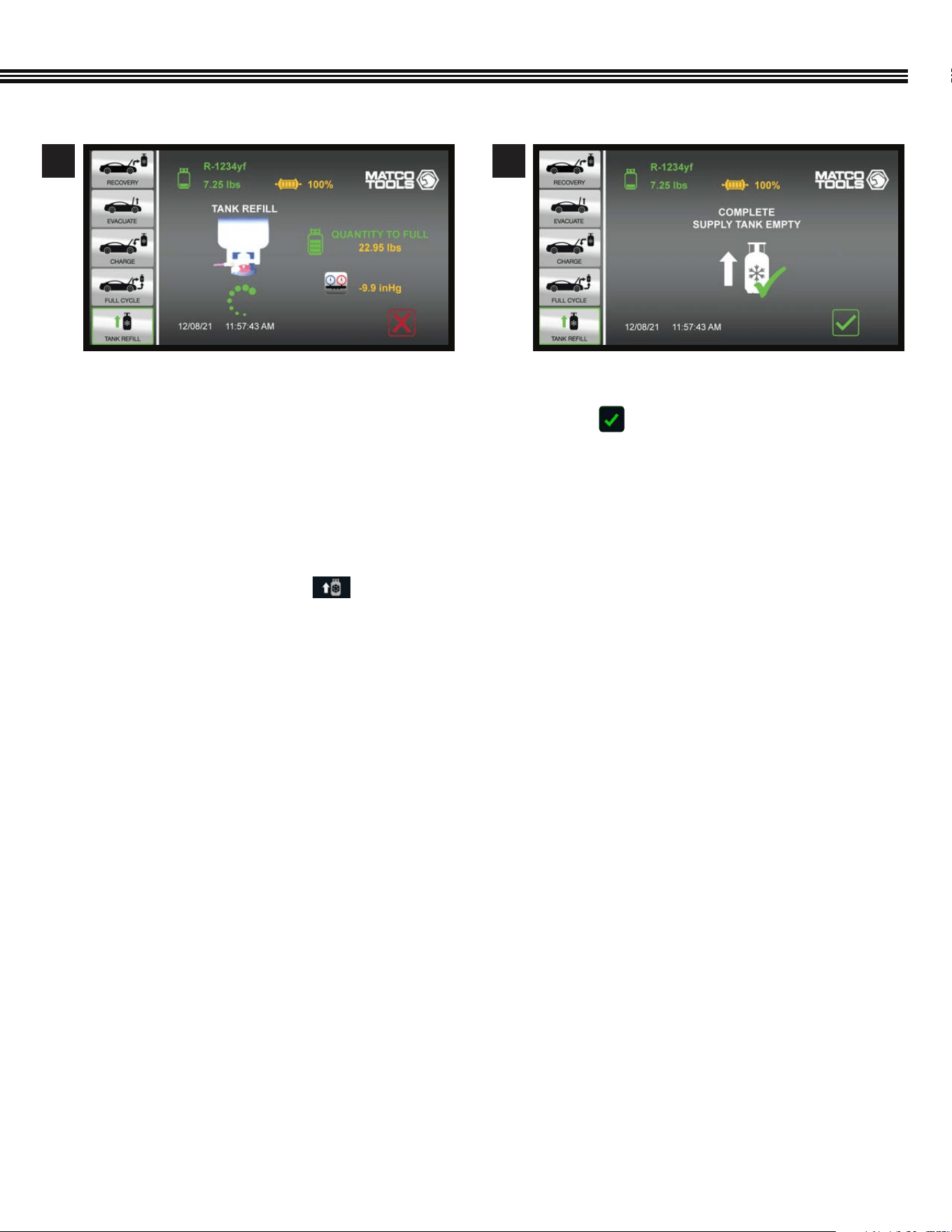
REFRIGERANT TANK REFILL (Cont’d)
a. Rell function has been conmpleted (the SACDUAL
tank has been lled to capacity).
b. Touch to return to the Home Screen.
a. Refrigerant transfer in process (screen shows
weight of refrigerant that can still be transferred to
ACDUAL tank untill it is full).
5 6
7. A “NO PRESSURE DETECTED IN THE TANK!” message
will appear. Touch Continue to proceed.
8. A “STILL NO PRESSURE DETECTED!” message will
appear. Touch Continue to proceed.
9. The main menu will appear. Touch and refer
to page 30 (previous page) for further instructions
on how to ll the tank.
10. Please contact CPS* Technical Support if you have
any problems registering this machine.
NOTE: Repairs and service for the ACDUAL is provided
by CPS
®
Products, Inc. Please contact CPS technical
support (1-800-277-3808 (TF)) if you need assistance
with registration.
32
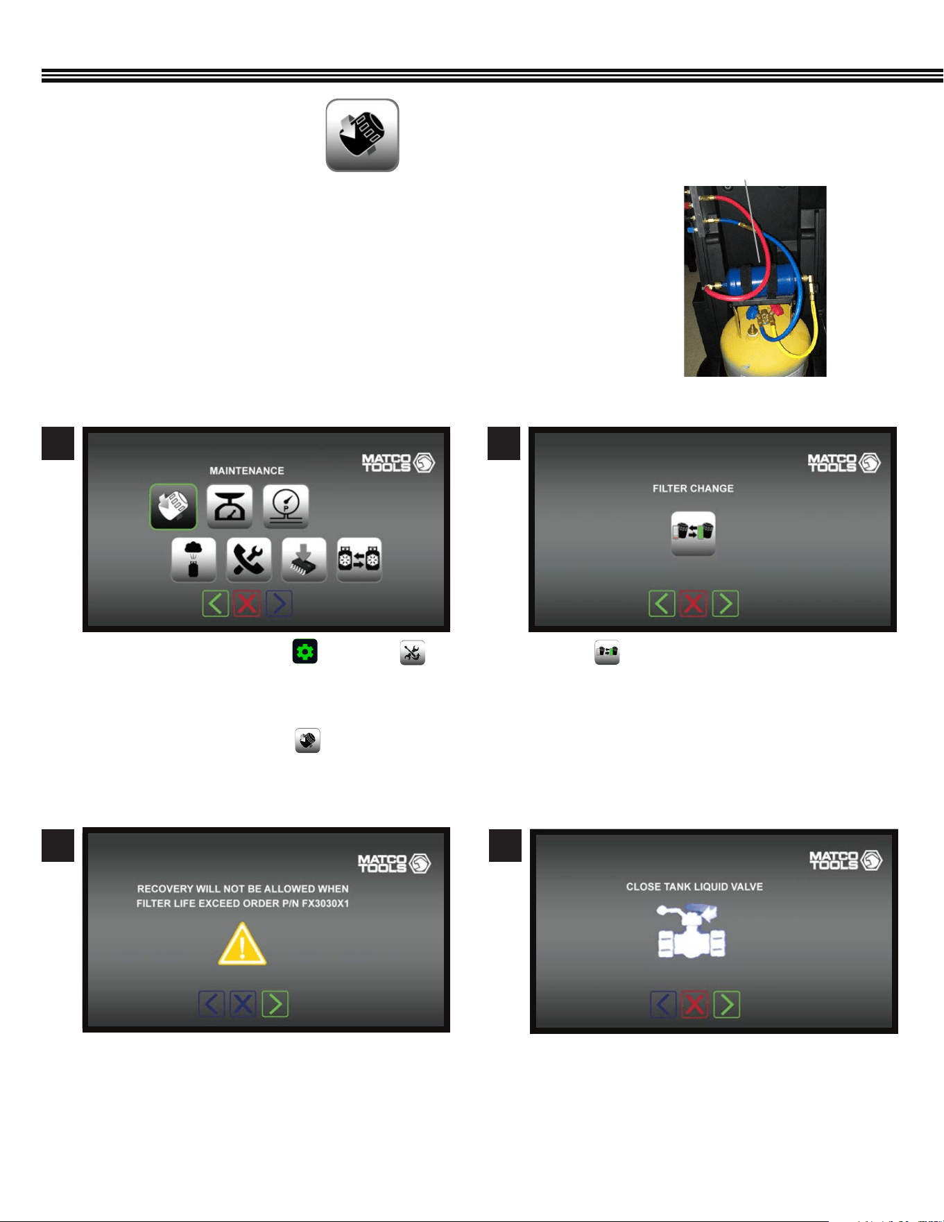
MAINTENANCE MENU
a. Touch to change the Filter/Dryer.a. On the Home Screen touch and select
from the Machine Upkeep Screen. Follow the
displayed directions and enter the “Filter Reset
Code” found in the NEW Filter/Dryer.
b. On the above screen, touch to change the
Filter/Dryer.
a. Close Liquid Valve on Recovery Tank Ball Valve.a. Refrigerant Recovery cannot be performed if Filter
Dryer life has been exceeded.
2
4
1
3
Maintenance − Filter/Dryer ChangeMaintenance Screen
Maintenance − Filter/Dryer ChangeMaintenance − Filter/Dryer Change
The included lter Filter/Dryer has the capacity to dry 150 Lbs of recovered refrigerant.
The remaining FILTER life is graphically displayed TOP CENTER of the HOME SCREEN.
When all 4 segments are no longer visible, change the Filter/Dryer.
FILTER/DRYER
(Not All Screens Are Shown)
Filter/Dryer
33
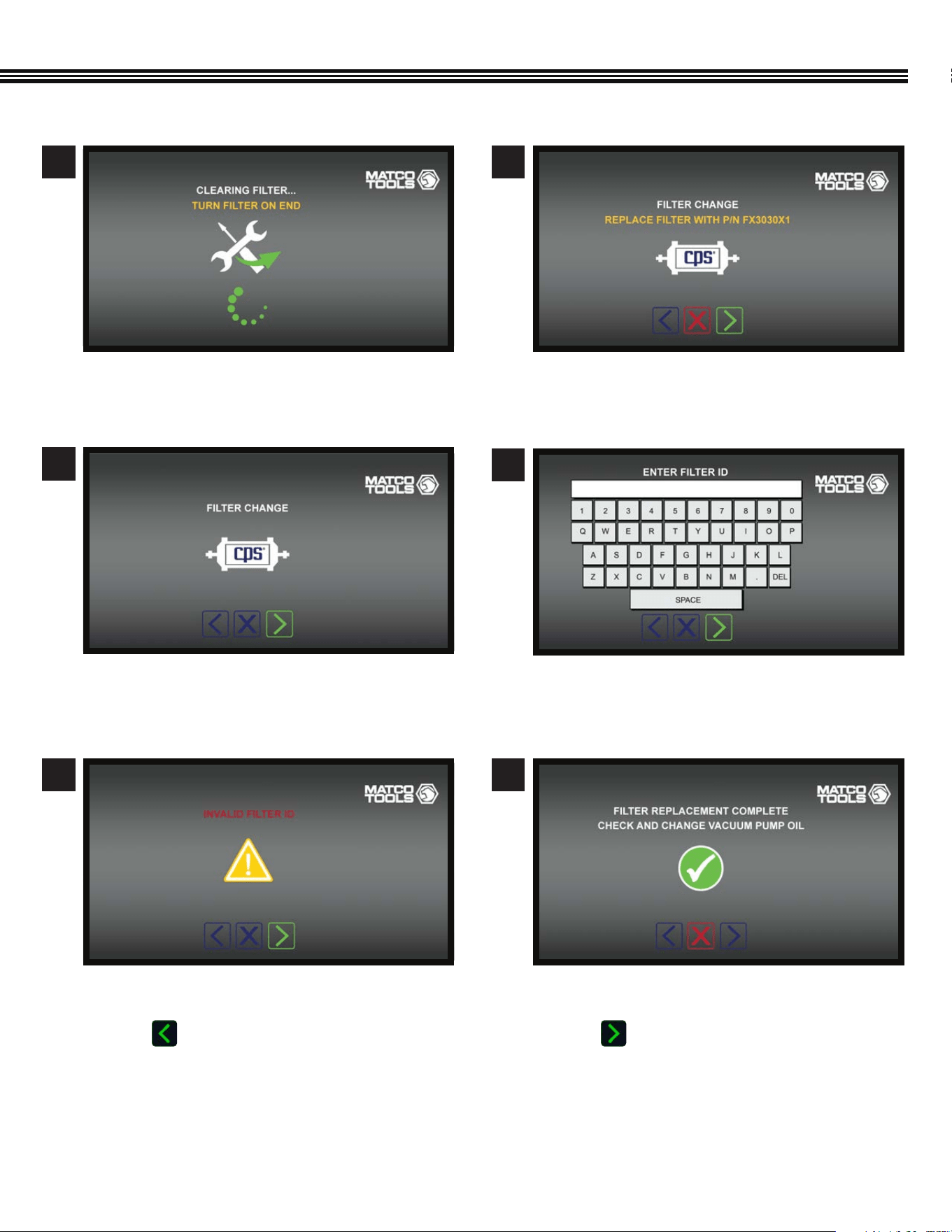
a. Filter Dryer replacement is complete.
b. Check or change the Vacuum Pump Oil.
c. Touch to move to the next screen.
Maintenance − Filter/Dryer Change
MAINTENANCE (Cont’d)
a. Replace the Filter Dryer with CPS part #FX3030X1.
a. Using the keypad, enter the NEW Filter Dryer ID #.
a. Install the Filter Dryer.
a. This screen will appear if an incorrect Filter ID#
has been entered.
b. Touch to return to the keyboard screen and
re-enter the correct Filter/Dryer ID #.
6
8
10
7
9
a. Turn Filter Dryer on end.
5
Maintenance − Filter/Dryer Change
Maintenance − Filter/Dryer Change
Maintenance − Filter/Dryer Change
Maintenance − Filter/Dryer Change
Maintenance − Filter/Dryer Change
34
MAINTENANCE (Cont’d)
Replacement parts for the ACDUAL are manufactured by CPS
®
Products, Inc. Please see the following recommendations for
replacement parts.
CPS® recommends replacing the oil with fresh CPS® brand Premium Vacuum Pump Oil when:
• Oil becomes contaminated (condensation, particles) or is discolored.
• A 100 hour run time break-in period has been reached.
• NOT RUNNING the pump for an extended time.
• Vacuum pump level is signicantly higher than the rated blank-off vacuum.
• When pump no longer reaches a desired vacuum level (test with a vacuum gauge attached directly on the pump).
• Depending on your oil type, application, and possible contaminants acquired when servicing A/C systems, oil change
frequency may range from daily to monthly.
CAUTION: DO NOT RUN THIS ACDUAL MACHINE WITH LOW OR NO OIL. RUNNING THIS EQUIPMENT WITH NO OR
IMPROPER OIL WILL CAUSE PREMATURE FAILURE.
OIL CHANGE PROCEDURE
PRO-SET® PREMIUM VACUUM PUMP OIL
1. Before draining the Vacuum Pump Oil from an ACDUAL machine, ensure oil is warmed up. If not, run pump for
10 minutes. Then, before draining oil, allow oil to reach room temperature.
If in doubt as to the temperature, use an infrared thermometer to check the housing temperature.
2. Turn ACDUAL Machine OFF then REMOVE POWER CORD FROM OUTLET.
3. Place ACDUAL Machine series pump over a suitable container for draining oil.
4. Remove Oil Drain CAP, then remove Oil Drain PLUG from drain port. AVOID CONTACT WITH HOT OIL. HOUSING
COMPONENTS MAY BE HOT. Let contaminated oil drain into suitable container. Reinstall OIL DRAIN PLUG.
5. Add fresh Pro-Set Premium Vacuum Pump Oil (by CPS) until level is between the MAX and MIN lines on
the pump housing.
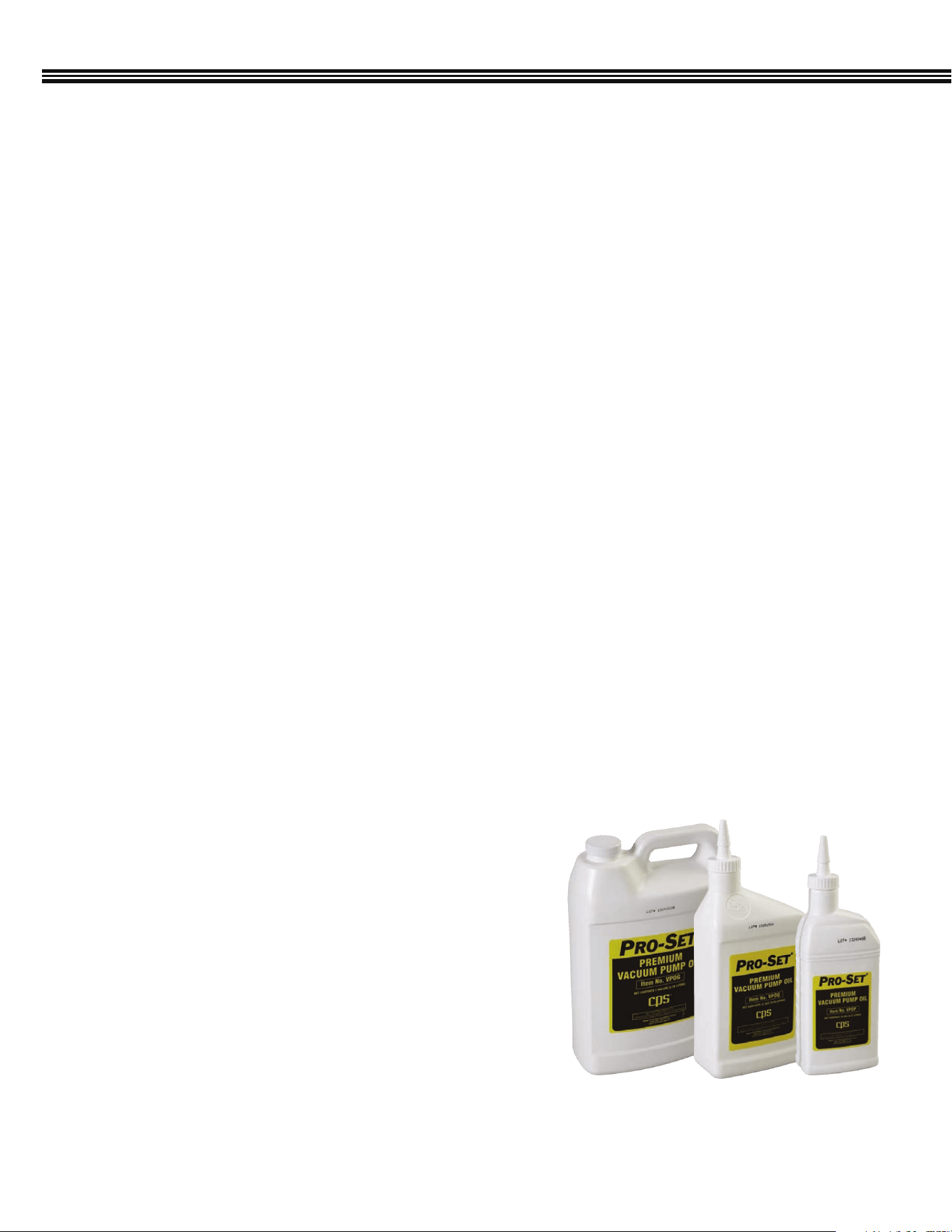
Pro-Set® Premium Vacuum Pump Oil is an extremely high quality,
severely hydro-treated vacuum pump oil and can be used in pumps
made by most manufacturers.
Vacuum pump oil should always be clean and free of contaminants such
as moisture, acids, vapors, dirt etc., to extend the life of your pump. So,
replace the oil at the appropriate interval with Pro-Set Premium Vacuum
Pump oil (available in pints, quarts and gallons).
VPOG6
(1 Gallon, 6/Case)
VPOQ12 (1 Quart, 12/Case)
VPOP12 (1 Pint, 12/Case)
VPOG (1 Gallon)
VPOQ (1 Quart)
VPOP (1 Pint)
VACUUM PUMP OIL CHANGE (FREQUENCY)
35
MAINTENANCE (Cont’d)
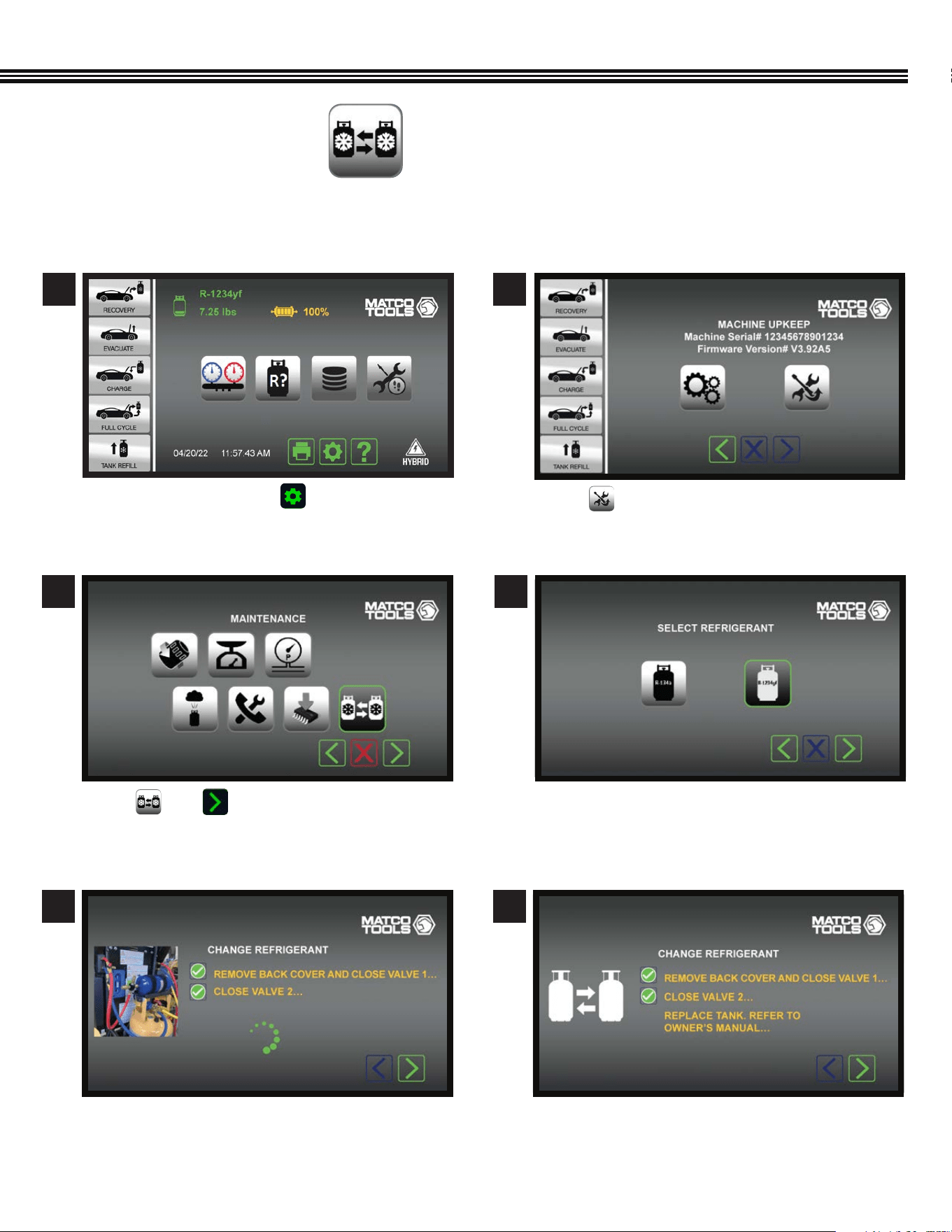
Touch then .
Follow onscreen instructions to close both valves 1
and 2. The ACDUAL unit indicates when complete.
After a 3 – 5 minute purge/deep vacuum to remove
any remaining trace of the refrigerant, you will be
prompted to replace tank.
Touch icon to select refrigerant type:
• R-134a
• R-1234yf
REFRIGERANT CHANGE
(Not All Screens Are Shown)
3
5 6
4
On the Home Screen touch to access the
MACHINE UPKEEP Screen.
Touch to enter the MAINTENANCE MENU.
1 2
Home Screen
Maintenance Menu Screen
Change Refrigerant Screen Change Refrigerant Screen
Select Refrigerant Screen
Machine Upkeep Screen
The ACDUAL Refrigerant Change function feature allows you to switch between the R-134a and R-1234yf refrigerant type;
specic to that used in the vehicle.
36
MAINTENANCE (Cont’d)
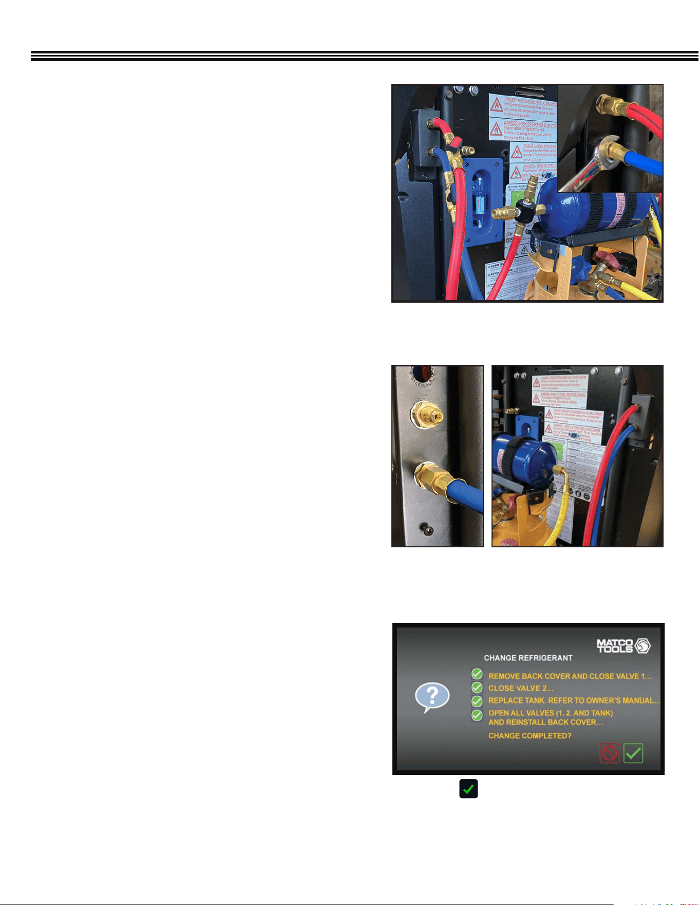
REFRIGERANT CHANGE (continued)
1. Disconnect Tank from the ACDUAL
Once the the refrigerant is purged, disconnect the tank
from the ACDUAL unit:
1. Using a Philips head screwdriver, remove the hose
bracket cover (Figure 1) located on the left-side of
the back of the unit.
2. Then, using a
9
⁄16” wrench, disconnect both the tank’s
liquid feed hose (red) and the vapour return hose (blue)
from the unit. (Figure 1; inset)
2. Connect New Hoses to Unit and Tank Filter Bracket
After the old tank has been removed:
1. Using a
9
⁄16”wrench, connect the new hoses to the
¼” SAE Male brass ttings (Figure 2) located on the left
side of the unit (red hose on top, blue hose on bottom)
2. Then, attach the red hose to the lter bracket and the
blue hose to the new tank.
3. Open all valves to check for leaks.
Neither MATCO nor the refrigerant supplier is responsible
lost refrigerant.
3. Replace the Service Hoses
Service hoses are located on the right-side of the back of
the unit, again, red (top), blue (bottom). (Figure 3)
1. Using a Philips head screwdriver, remove the hose
bracket cover.
2. Disconnect the service hoses with a
9
⁄16” wrench and
attach the new service hoses.
3. Once attached, re-install the hose bracket cover.
4. Refer back to screen as the unit goes through the
Refrigerant Identication process to ensure proper
changeover. (Figure 4)
Fig 1: Disconnect hoses on the left side, back of
the ACDUAL unit.
Fig 2: 1/4” SAE
Male ttings
Fig 3: Service hoses attached to
right-side, back of unit.
Change Refrigerant Conrmation Screen
Fig 4: Select to conrm that all steps have been
completed so that the unit can run through the
refrigerant identication process.
37
MAINTENANCE (Cont’d)
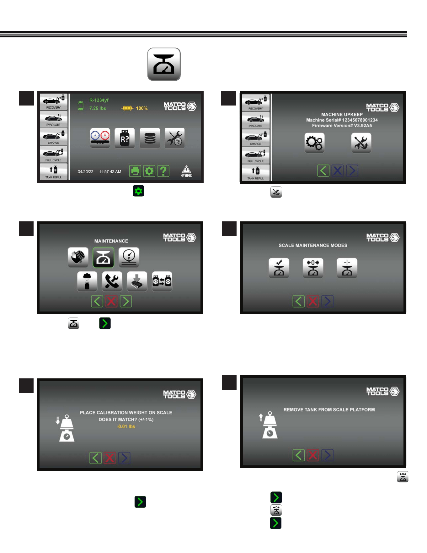
a. Touch then .
a. On the “Scale Maintenance Modes” screen, touch
b. Remove the refrigerant tank from the scale.
c. Touch .
b. Touch to reset the emplty tank weight to zero.
e. Touch to move to next screen.
a. Touch Maintenance Mode Icon to: (left to right)
• Check Calibration
• Tare (Zero) the Scale
• Scale Calibration (ACDUAL Scale calibration is
only provided by CPS
®
Products, Inc.).
a. Set the included 1 lb weight on the scale.
b. If the scale weight in within =/- 1% of 1lb
(0.99 – 1.01 lbs), touch the icon.
MAINTENANCE MODES
(Not All Screens Are Shown)
3
6
4
5
a. On the Home Screen touch to access the
MACHINE UPKEEP Screen.
a. Touch to enter the MAINTENANCE MENU.
1 2
Home Screen
Maintenance Menu Screen
Tare (Zero) The Scale
Scale Maintenance Modes
Check Calibration Screen
Machine Upkeep Screen
38
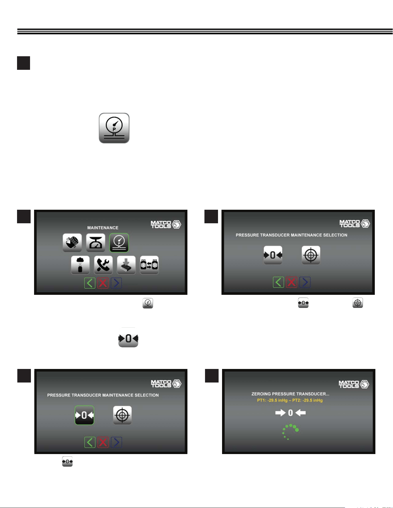
a. On the Maintenance Screen, touch .
1
a. Touch either the “Tare” or “Calibrate”
keys.
a. Wait while PT1 zeros out.a. Touch to “Tare” (zero out) the Pressure
Transducer (PT).
2
43
MAINTENANCE (Cont’d)
Zero The Pressure Transducer Zero The Pressure Transducer
The internal pressure transducers are used during recovery, vacuum, air purge and in the manifold mode. Access this menu if
you suspect that the internal pressure transducer readings are inaccurate.
- Calibration will require a certied pressure source above 70 PSIG.
- Follow the displayed direction for the select transducer maintenance function.
- Select Maintenance Mode for Pressure Transducer.
PRESSURE TRANSDUCER (Tare Or Calibrate)
(Not All Screens Are Shown)
Tare (Zero) The Pressure Transducer
(Not All Screens Are Shown)
Actual scale calibration is suggested only if the calibration test was off by more than 0.02 lbs.Calibration may
be performed by a CPS® authorized service center. CPS Technical Support can also assist with the process.
Scale calibration requires a certied 25 lb weight.
7
Note: The scale is powered by the ACDUAL machine (no batteries to replace)
39
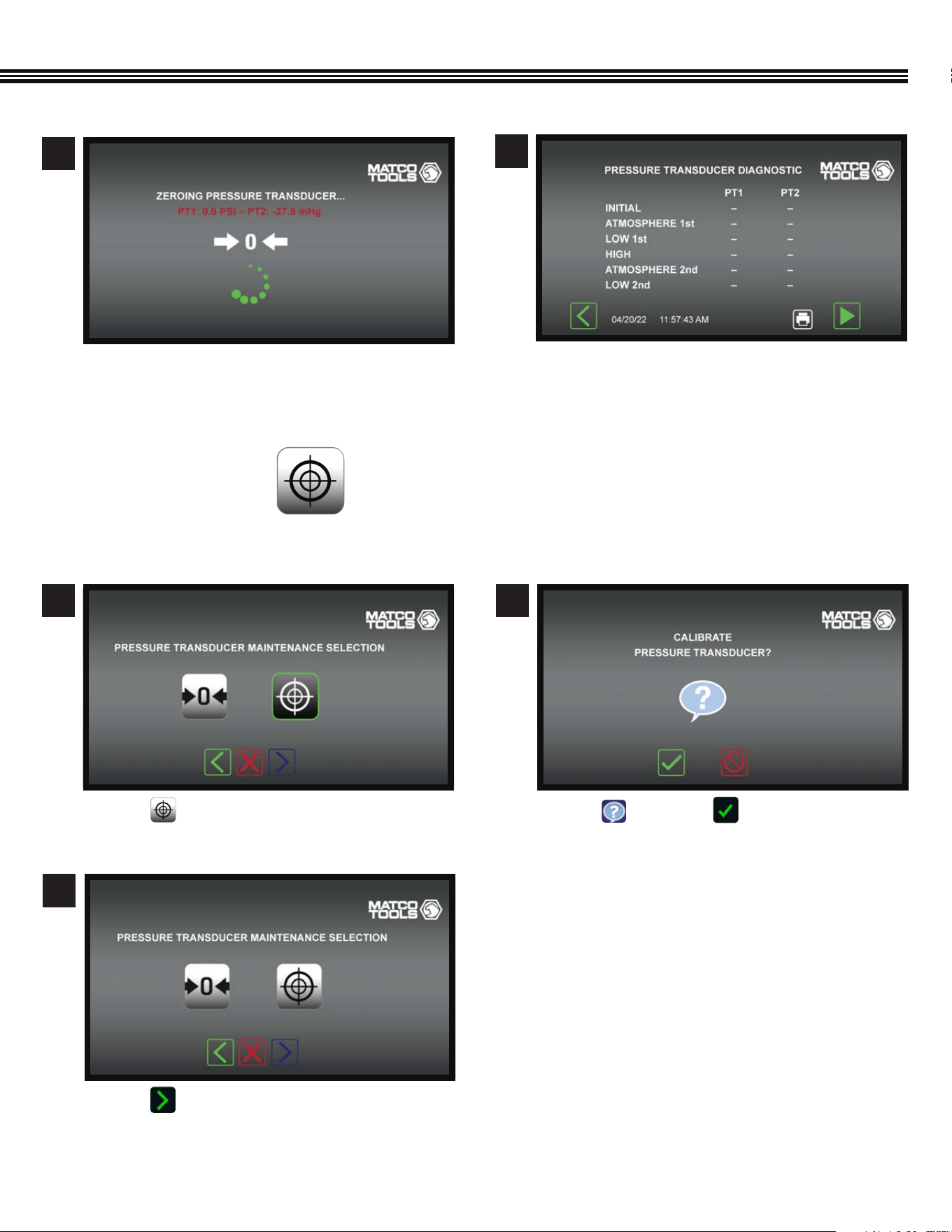
a. Touch for HELP or to proceed.
a. Touch to proceed to the next Maintenance
step.
a. Touch to calibrate the Pressure Transducer.
2
3
1
Calibrate Pressure Tranducer
Calibrate Pressure Tranducer
Calibrate Pressure Tranducer
Calibrate Pressure Transducer
(Not All Screens Are Shown)
Zero The Pressure Transducer Zero The Pressure Transducer
a. Wait while PT2 zeros out.
a. Chart will populate with PT data
5
6
MAINTENANCE (Cont’d)
40
Automatice Air PurgeMaintenance Screen
Automatice Air Purge
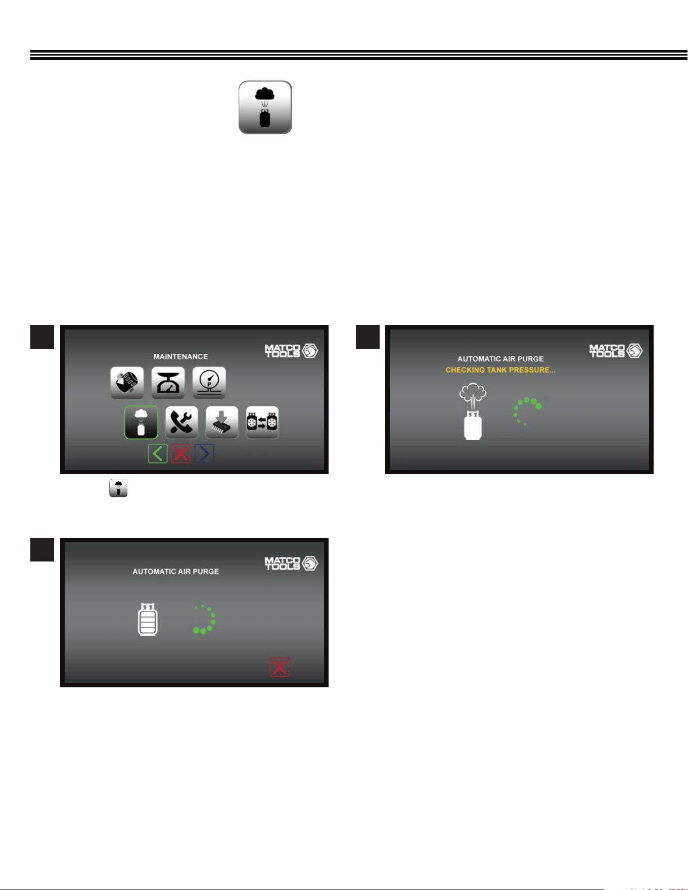
a. Touch on the Maintenance Screen.
a. Automatic Air Purge in process.
b. When Air Purge has been completed, the
Maintenance Home Screen will appear.
a. The ACDUAL will check the Refrigerant Tank
Pressure.
1
3
2
MAINTENANCE (Cont’d)
The ACDUAL features automatic air purge at machine start up. Air Purge may also be selected in the Maintenance Mode. Air
Purge reduces “non-condensable gases” in the storage tank to an acceptable level and may take a few minutes to complete.
DO NOT TURN THE MACHINE OFF OR UNPLUG THE MACHINE DURING AN AIR PURGE CYCLE.
1. This mode should only be entered with direction by CPS® Products Technical Support or by a CPS® Authorized
Service Center.
2. This mode enables the testing of each device controlled by the ACDUAL computer. These devices include the ball valves,
vacuum pump, compressor and pressure transducers.
AUTOMATIC AIR PURGE
(Not All Screens Are Shown)
41
DIAGNOSTICS OF INDIVIDUAL VALVES, CONTROLS, SCALE, TANK, ETC
(Not All Screens Are Shown)
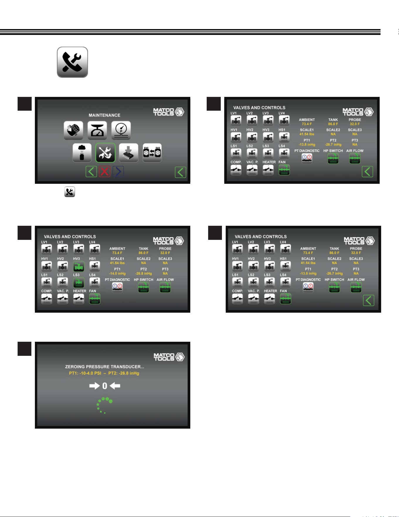
a. List of Valves, Controls, PT’s Scale, etc. to select
for disgnostics.
a. Or, select PT1 or PT2 for diagnostics.
a. Touch (Valves & Controls Icon).
a. Select a valve or control for individual diagnostics.
a. Zeroing PT1 & PT2.
2
4
4
3
5
1
MAINTENANCE (Cont’d)
Valves & Controls Screen
Valves & Controls ScreenValves & Controls Screen
42
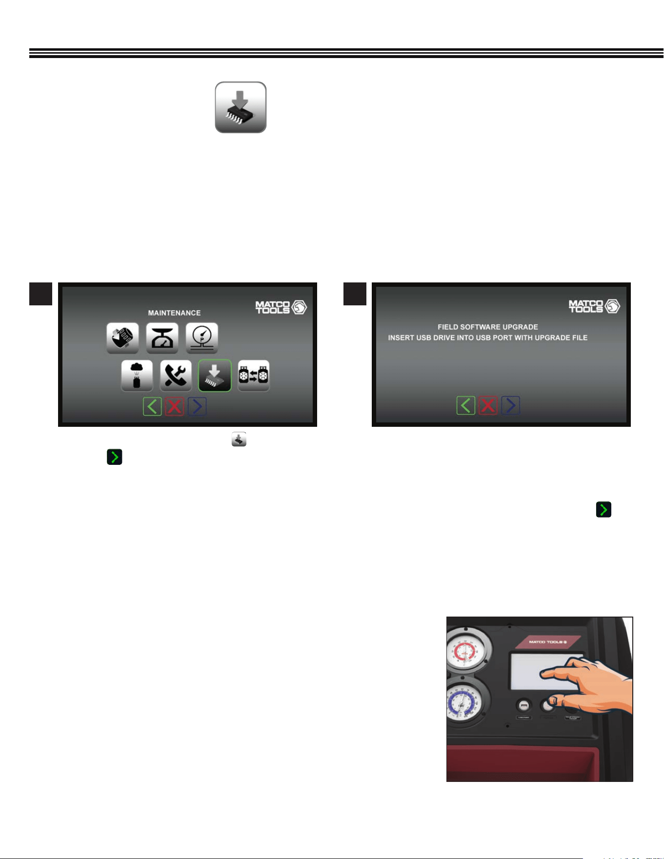
Use this mode to update the ACDUAL system software.
Loading New Firmware
1. The latest ACDUAL rmware can be downloaded at https://www.cpsproducts.com/support/rmware-updates/.
2. Select the ACDUAL model and follow the instructions also available on this page.
MAINTENANCE (Cont’d)
a. Touch the SOFTWARE UPGRADE key.
b. Touch to proceed to the next screen.
a. To upgrade the ACDUAL software in the eld,
insert a USB drive (with an upgraded le) into USB
Port on the Control Panel.
b. Ensure power remains on during this operation.
c. After new software has been loaded, touch to
move to the next screen.
1 2
Software UpgradeMaintenance Menu
FIELD SOFTWARE UPGRADE
(Not All Screens Are Shown)
TOUCH SCREEN DISPLAY CALIBRATION
Under certain conditions, the touch screen may lose its calibration
(i.e., touches on the screen don’t result in the desired result). When touching
a screen function key, if it does not actuate the function, or engages an
adjacent function, the screen needs to be calibrated.
Touch Screen Calibration:
1. Turn the machine’s power off.
2. Then, while pressing and holding any spot on the touch screen turn the
power back on. A screen SET UP menu will be displayed.
3. Select Screen Calibration and follow the on-screen directions. (next page)
4. Calibration is then complete.

43
a. Touch screen to continue.
a. Touch and release the lled circle (UPPER RIGHT).
a. Touch and release the “lled” circle (UPPER LEFT).
a. Touch and release the lled circle (LOWER RIGHT).
1
3
2
4
TOUCH SCREEN DISPLAY CALIBRATION (Cont’d)
5
7
6
8
a. Touch and release the lled circle (LOWER LEFT). a. Touch anywhere to check for accuracy
b. Touch rectangle to conrm accuracy.
c. Wait timrout to REPEAT calibration.
a. To repeat calibration, reset the board while touching
the screen until calibration prompt appears.
44
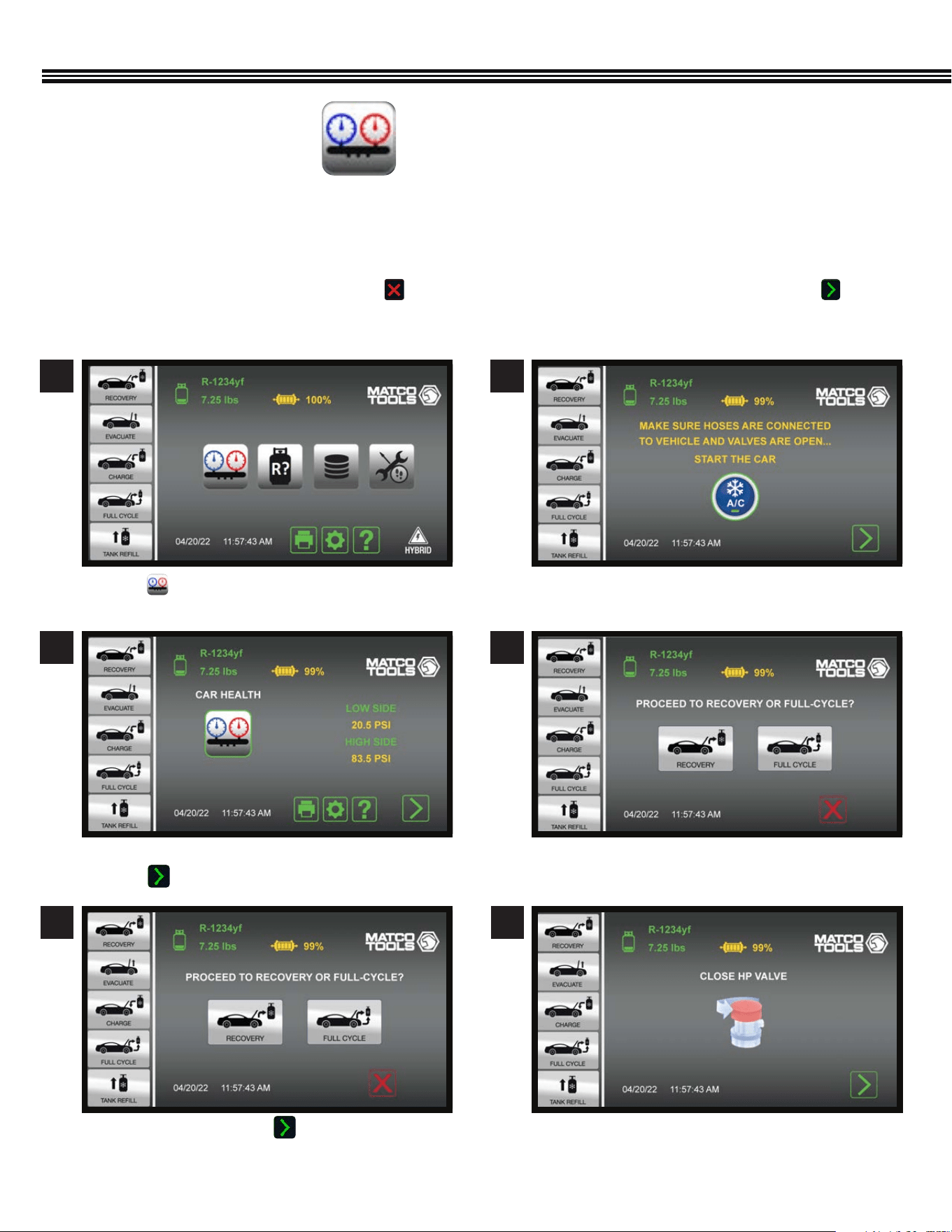
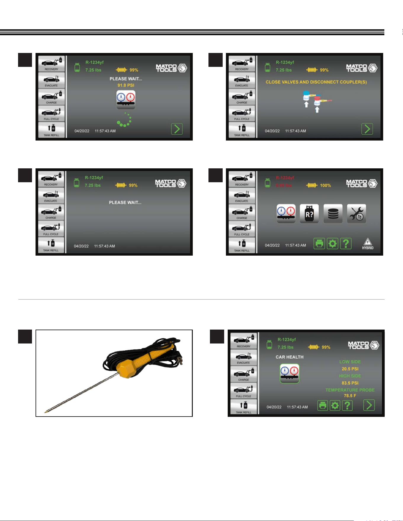
Use this mode for checking system pressures and vent temperature before and after servicing the A/C system.
1. System parameters can be printed while in this mode to provide a before and after comparison.
2. When entering the Car Health mode, the machine will provide a prompt to start the vehicle’s A/C system.
3. Readings can then be collected and printed.
4. If Refrigerant Recovery is planned next, touch . This will take users to the Home Screen. If all is well, touch and
the machine will guide users through clearing the hoses of refrigerant back into the AC system.
CAR SYSTEM HEALTH MODE
a. Touch to view vehicle’s AC system Low & High
Side Pressures, and Probe Temperature (if used).
a. Ambient, High & Low Side pressures shown
b. Touch to proceed o next screen.
a. CONFIRMATION - Touch to proceed to
RECOVERY or FULL CYCLE.
a. Ensure HOSES are CONNECTED TO VEHICLE and \
VALVES are OPEN.
a. Select RECOVERY or FULL CYCLE.
a. CLOSE HIGH PRESSURE VALVE.
CAR SYSTEM HEALTH MODE
(Not All Screens Are Shown)
1
3
2
4
5 6
Home Screen
45
CAR SYSTEM HEALTH MODE (Cont’d)
7 8
9 10
a. Wait.
a. Wait. a. Home Screen.
a. CLOSE VALVES and DISCONNECT COUPLERS.
CORDED TEMPERATURE PROBE ACCESSORY #TMX2P (INCLUDED)
1
The TMX2P has a 15’ (4.5m) cord is commonly used to measure vent or liquid temperatures in vehicles. It has an operating
temperature range of
-40˚F to 257˚F / -40˚C to +125˚C.
a. At any time, plug the end of the corded
Temperature Probe into the RCA jack on the
FRONT of the ACDUAL Control Panel.
b. Insert the probe end into a vehicle’s A/C Vent
or other location where a temperature reading is
needed (Note: Keep metal portion of probe away
from any moving or electrical parts).
a. View the resulting temperature in the Car System
Health Mode section, or in the Valves & Controls
Screen #2,3 or 4 on page 39.
2
46
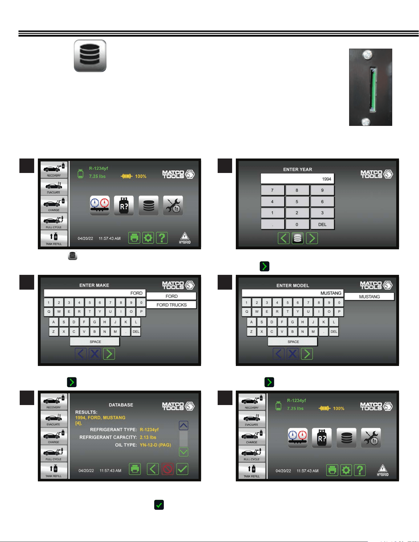
A/C DATABASE FOR NORTH AMERICAN VEHICLES
A/C DATABASE FOR NORTH AMERICAN VEHICLES (Since 1994)
(Not All Screens Are Shown)
1 2
a. Touch . a. Use keypad to enter YEAR vehicle was made.
b. Touch to enter data and proceed to next screen.
3 4
a. Enter vehicle “MAKE” (BRAND).
b. Touch to enter data and move to next screen.
a. Enter vehicle MODEL NAME.
b. Touch to enter data and move to next screen.
NORTH AMERICAN VEHICLE A/C DATA BASE
1. Insert the included SD Card (Secure Digital Memory Card) into the back of the ACDUAL machine.
2. An “End User License Agreement” (see APPENDIX in this manual) will appear on the ACDUAL color screen.
3. By accessing any of the motor databases via this website, you automatically agree to all the the terms
and conditions of this agreement. If you do NOT agree to all terms and conditions, do NOT access or use
the databases.
4. This database shows the type and weight of all refrigerants/oil used in vehicles sold in North America
since 1994.
SD Card Slot On
Back Of ACDUAL
Machine
5 6
a. AC Database will provide REFRIGERANT TYPE,
REFRIGERANT CAPACITY AND REFRIGERANT OIL TYPE
b. If all information shown is OK, touch to enter
data and move to next screen.
47
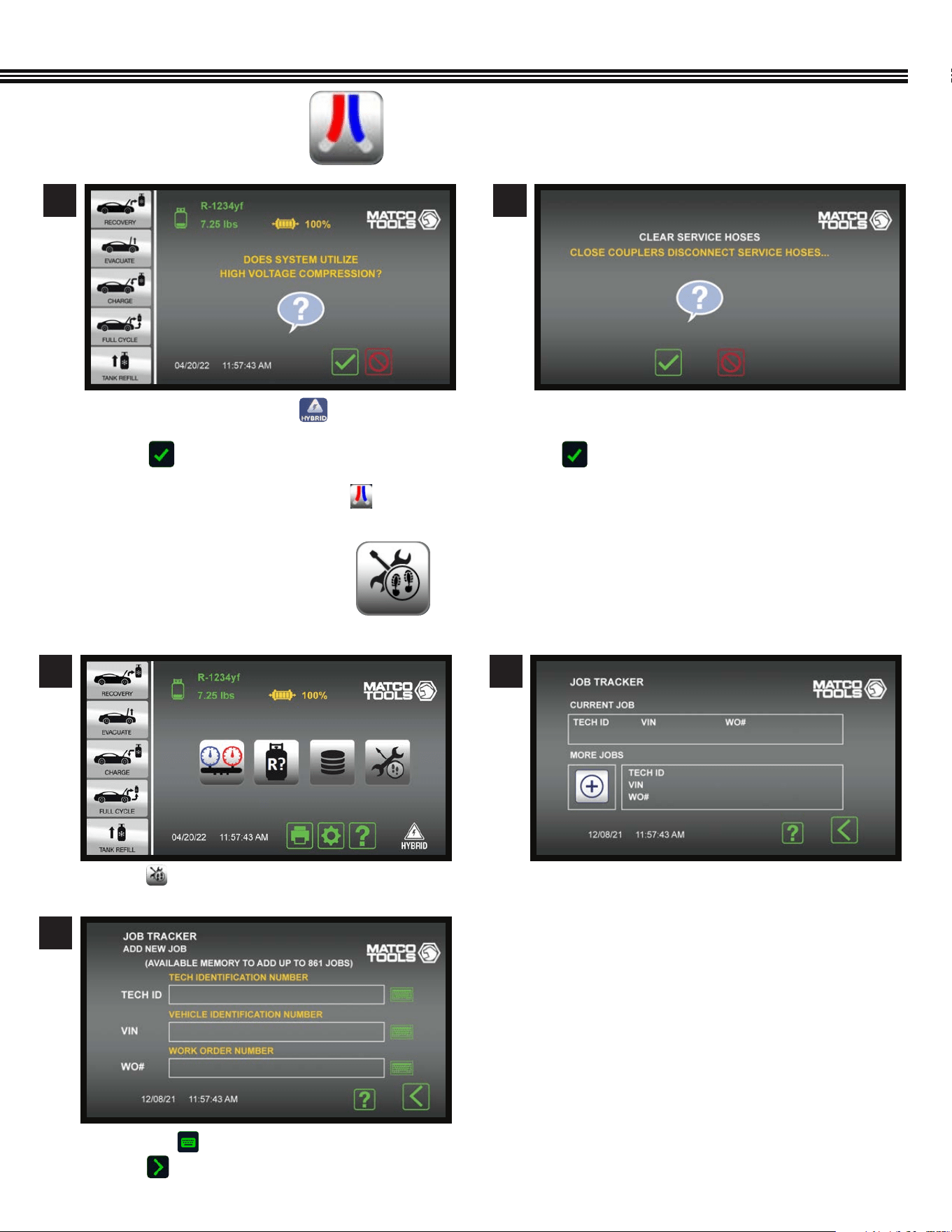
a. On the HOME screen, touch if the vehicle is
Hybrid/Electric to ush service hoses.
b. Touch to continue.
If machine is in non-SAE mode, touch to ush
service hoses.
FLUSH REFRIGERANT HOSES
(Not All Screens Are Shown)
1 2
a. If you want to Clear Service Hoses (of refrigerant), CLOSE
COUPLERS and DISCONNECT SERVICE HOSES, then
b. Touch to continue.
c. The Home Screen will appear after the clearing process
has been completed
1 2
JOB TRACKER
(Not All Screens Are Shown)
a. Touch on the Home Screen. a. If CURRENT JOB data was previously entered, it
will appear in TOP portion of screen.
b. Touching the “+” icon brings up the next screen.
c. Enter your Shop Password.
Home Screen Current vs More Jobs Screen
3
a. Touch any to enter data for each eld.
b. Touch to proceed to next screen.
FLUSH REFRIGERANT HOSES
48
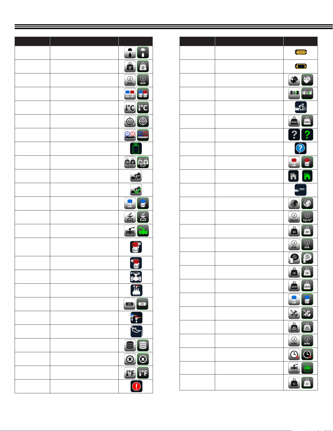
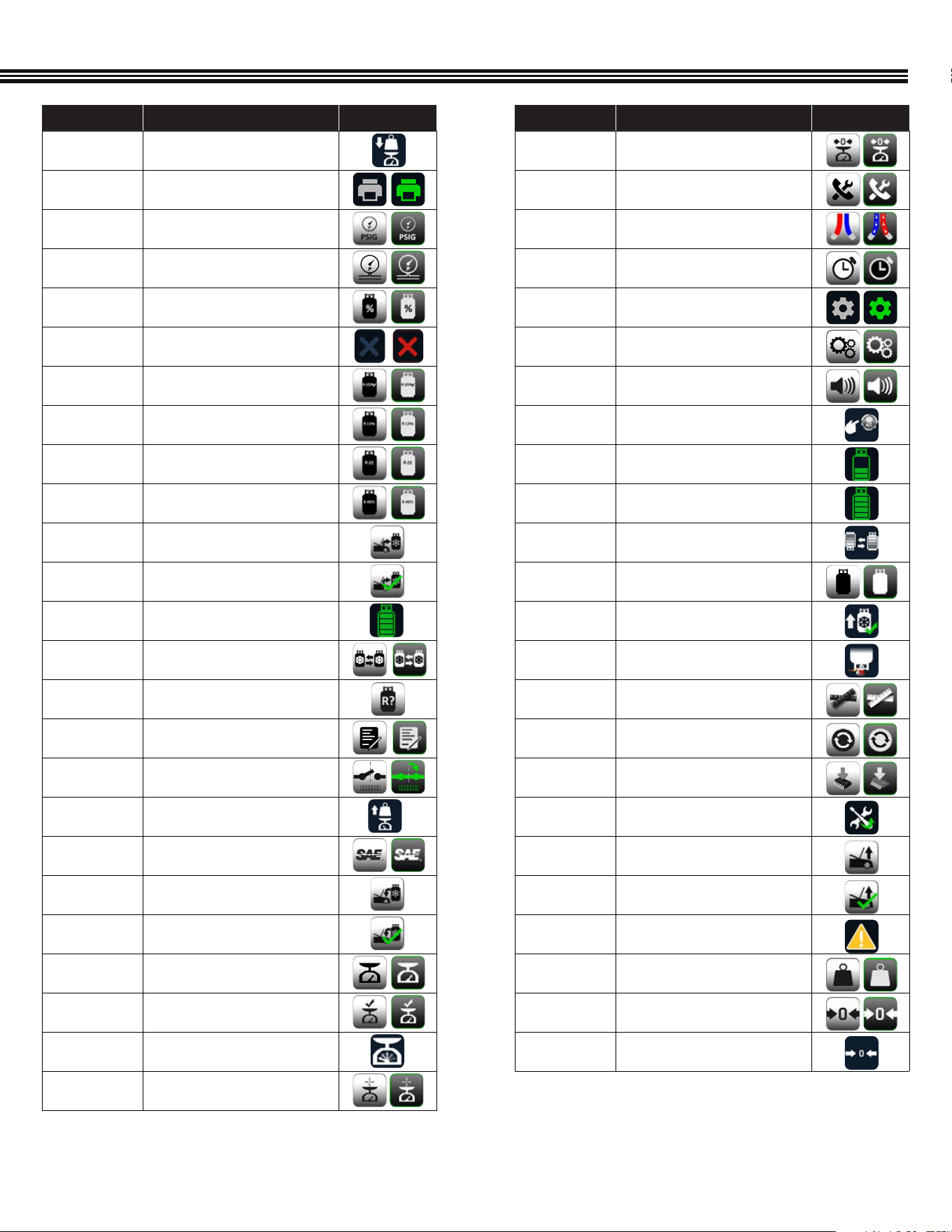
APPENDIX (Complete Icon Library)
ICON NAME DESCRIPTION OFF/ON
FILTER
Displays the current status of the
lter life.
FILTER CHANGE
Displays when a lter change is
required
FILTER CHANGE
Touch to CHANGE FILTER
FILTER CHANGE
Touch to CHANGE FILTER
FULL CYCLE
COMPLETE
Indicates that the FULL CYCLE service
is COMPLETE
GRAMS
Touch to select GRAMS as UOM
HELP
Touch to launch the HELP Menu
HELP
Provides Firmware version
HIGH COUPLER
Touch to select the HIGH SIDE coupler
only
HOME
Touch to launch the HOME screen
INJECTION
Noties the user to INJECT oil and/or
dye at this point in the service
INTERNATIONAL
Touch to select INTERNATIONAL UOM
KGCM2
Touch to select KGCM2
KGS
Touch to select KGS as UOM
KPA
Touch to select KPA
LANGUAGE
Touch to select LANGUAGE
LBS
Touch to select LBS as UOM
LBS:OZ
Touch to select LBS:OZ as UOM
LOW COUPLER
Touch to select the LOW SIDE coupler
only
MAINTENANCE
Touch to launch the MAINTENANCE
menu
METRIC
Touch to select METRIC UOM’s
MPA
Touch to select MPA
NOT NOW
Touch to postpone suggested
operation
Open Ball Valve
Press to Open Ball Valve
OZ
Touch to select OZ as UOM
ICON NAME DESCRIPTION OFF/ON
AIR PURGE
Touch to select AIR PURGE
AMERICAN
Touch to select AMERICAN Units
BAR
Touch to select BAR
BOTH
COUPLERS
Touch to select BOTH couplers
° C
Touch to select CELSIUS
CALIBRATION
Touch to select CALIBRATION
CAR SYSTEM
HEALTH MODE
Touch to launch CAR SYSTEM HEALTH
MODE
CHANGE TANK
The CHANGE TANK icon noties the
user to change the tank
CHANGE UOM
Touch to change the unit of
measurement
CHARGE
Touch to perform a CHARGE service
CHARGE
COMPLETE
Indicates that the CHARGE service is
COMPLETE
Charge Low
Side
Press to select Low Side Charging
CHECK SCALE
COMPLETE
The SCALE CHECK COMPLETE noties
users that a scale check is complete
Close Ball
valve
Press to close ball valve
CLOSE
COUPLER
The CLOSE COUPLER icon noties
the user to close the coupler during
a recharge service
CLOSE HP
Noties the user to CLOSE HP valve
during a CHARGE service
CLOSE VALVE
Noties user to CLOSE VALVE
CONNECT HP
Noties user to connect HP port
during tank rell
CPS FILTER
CPS FILTER
DISCONNECT
COUPLERS
Noties the user to DISCONNECT
COUPLERS
DRAIN OIL
The DRAIN OIL icon noties the user
that oil is draining from the vehicle
END-USER
AGREEMENT
Touch to access the End-User License
Agreement
ERROR
Displays when there is an ERROR
° F
Touch to select FARENHEIGHT
FAILED
Indicates that a given operation FAILED
49
ICON NAME DESCRIPTION OFF/ON
PLACE WEIGHT
Noties user to PLACE WEIGHT on the
scale
PRINT
Touch to PRINT a report of the service
PSIG
Touch to select PSIG
PT
Touch to select PRESSURE
TRANSDUCER
PURITY
PURITY
QUIT
Touch to quit the current function
R-1234yf
Touch to select R-1234yf Refrigerant
R134a
Touch to select R134a Refrigerant
R22
Touch to select R22 Refrigerant
R407
Touch to select R407 Refrigerant
RECOVERY
Touch to perform an RECOVERY service
RECOVERY
COMPLETE
Indicates that the RECOVERY service is
COMPLETE
REFRIGERANT
REFRIGERANT
REFRIGERANT
CHANGE
Touch to CHANGE REFRIGERANT
REFRIGERANT
IDENTIFICATION
Touch to perform REFRIGERANT
IDENTIFICATION process
REGISTER
Touch to REGISTER unit
RELAY
Touch to select RELAY
REMOVE
WEIGHT
Noties user to REMOVE WEIGHT from
scale
SAE
Touch to select SAE
SAE CHARGE
Touch to perform a SAE CHARGE
service
SAE CHARGE
COMPLETE
Indicates that the SAE CHARGE service
is COMPLETE
SCALE
Touch for SCALE functions
SCALE CHECK
Touch to perform SCALE CHECK
SCALE CHECK
The SCALE CHECK icon noties users
that a scale check is in progress
FULL
CALIBRATION
Touch to perform full calibration
APPENDIX (Complete Icon Library)
ICON NAME DESCRIPTION OFF/ON
SCALE ZERO
Touch to RE-ZERO the scale
SERVICE
Touch to select SERVICE
SERVICE HOSES
BEING FLUSHED
Indicates that the SERVICES HOSES
are BEING FLUSHED
SET TIME
Touch to SET TIME
SETTINGS
Touch to launch the SETTINGS screen
SETUP
Touch to launch the SEUP menu
SPEAKER
Touch to enable sound
START AC
Noties user to start vehicle and turn
on AC during service
TANK
Indicates the level of refrigerant in
the TANK
TANK FULL
Noties user that TANK is FULL
TANK REFILL
Touch to perform a TANK REFILL
Tank Tare Setup
Press to change tank weight and WC
TANKS REFILL
COMPLETE
Indicates that the TANK REFILL is
COMPLETE
TURN UPSIDE
DOWN
Noties user to TURN TANK UPSIDE
DOWN during tank rell
UNIT
Touch to select UOM
UPDATE
Touch to UPDATE
UPGRADE
Touch to select UPGRADE
UPKEEP
Touch to launch the UPKEEP menu
VACUUM
Touch to perform a VACUUM
service
VACUUM
COMPLETE
Indicates that the VACUUM service is
COMPLETE
WARNING
The WARNING icon appears to caution
users of a potential hazard
WEIGHT
Touch to Choose WEIGHT UOM
ZERO
Touch to RE-ZERO the pressure
transducer
ZEROING
Indicates that the unit is ZEROING

50
“E1-BAD TXT EPROM”; A bad scale may cause this, also.
“E2-SCALE ADC”; Connection to the scale electronics lost.
“E3-SCALE EPROM”; Scale not calibrated?
“E4-CANNOT CAL”; Scale cannot be calibrated or bad calibration.
“E5-MBV FAULT: X”; Where X is a number from 1 to 5 indicating which MBV has failed.
“E6-AMB. THRM”; Ambient thermistor in the “head” is bad.
“E7-TNK THRM”; Thermistor attached to the oil sep. is bad.
“E8-PT TRANS”; Pressure transducer is bad.
“E9-WEAK BATT”; Should never appear.
“E10-BAD FILTERTIME”; Filter code problems.
“E11-DEFAULTS NOT SET”; What it says…
“E12-BAD GRAPH MEM”; Problems with the graphics like Chinese and Russian.
“E13-BAD PTR. TO INFO MEM”; Major software corruption, fatal error.
“E15 FLOW SWITCH ERROR” Air ow switch is open.
“UNKNOWN ERROR”; Cause of problem cannot be identied
ACDUAL ERROR CODES
Part Number Description
FX3030X1 FX Series Maintenance Kit—Filter, Vacuum Pump oil and Coupler O-rings
QCL134 Auto Coupler Brass Low Side 14mm
QCH134 Auto Coupler Brass High Side 14mm
AR2788X14A R134a Rell Hose Adaptor 1/2 ACME
AR2788X14B R134a Rell Hose Adaptor 1/4 SAE
CRX430T 30lb 400psi Recovery Tank
CRX400T 50lb 400psi Recovery Tank
481500 / 481500YF Spotgun™ Oil Injection Kit
REPLACEMENT PARTS
“00001” Error #1: The air or gas readings were unstable.
• Solution: Move the unit away from sources of EMF or RFI
such as radio transmitters and arc welders.
“00002” Error #2: The air or gas readings were excessively high.
• Solution: Move the unit away from sources of EMF or RFI
such as radio transmitters and arc welders.
“00003” Error #3: The air calibration resulted in a low output.
• Solution: Prevent refrigerant from owing into the unit
through the sample inlet during air calibration.
• Solution: Allow any refrigerant in the atmosphere to
dissipate before performing air calibration.
• Solution: Verify that the air intake and the exhaust are
not obstructed
• Solution: Verify that the white lter is correctly plugged
into the rubber grommets.
“00004” Error #4: The unit is beyond the operating
temperature range
• Solution: Move the unit to an area where the ambient
temperature is within the specied operating range.
“00005” Error #5: The refrigerant sampled has an excessively
large amount of air or there was little or no sample ow due
to a closed valve or plugged sample lter. This is the code
to prompt the user to change the brass lter. This should be
considered more as a prompt than an actual error.
• Solution: Verify the coupler valve is open.
• Solution: Verify the sample lter is not plugged with debris
or oil.
• Solution: Replace brass sample lter
• Solution: Verify that the white lter is correctly plugged into
the rubber grommets.
“00006” Error #6: The air sensor has expired and must be
replaced before the analyzer can be used.
“00007” Error #7: The pressure read by the sensor has been
determined to be too high.
• Solution: Verify that the exhaust is not obstructed.
IDENTIFIER CODES

51
2-2-3 WARRANTY
Two Years Full Warranty
CPS
®
Products, Inc. (herein CPS), warrants this ACDUAL machine to be free from defects in materials, workmanship, and
components for Two Years from the date of purchase. If equipment should fail during the warranty period, it will be repaired
or replaced* (at our option), at no charge to the original owner. Any parts or labor required to repair a defective machine or
components covered under the warranty will be covered at no charge to the original purchaser of the machine.
Three Year Compressor Warranty
From the end of Year One through the end of Year Three, CPS will repair or replace (at our option)* the compressor (at
no charge to the original owner, except for labor) that is found to be defective.
Restrictions That Apply To This Limited Warranty:
• This machine must be used in normal use situations only (as described in this Owner’s Manual).
• This limited warranty does NOT apply if: This machine, or a product part is broken by accident; this machine is misused,
tampered with or modied in any way; this machine is used for recovering or recycling any substance other than the
specied refrigerant type.
• This machine must be serviced and maintained (as specied in this Owner’s Manual
• All warranty service claims must be made within the specied warranty periods mentioned above. Proof-of-purchase
date by the original owner must be supplied.
• Warranty or service claims are subject to authorized inspection for product defect(s).
• *At the discretion of CPS, any part that fails or must be repaired within the warranty period, may be a new or
reconditioned part.
• *At the discretion of CPS, if this machine fails or must be repaired within the warranty period, will be repaired or replaced
with a different reconditioned machine.
• All repaired equipment will carry an independent 90 day warranty.
• Transportation charges for warranty service will be reimbursed by CPS upon verication of the warranty claim and
submission of a freight bill for normal ground service. Approval from CPS must be obtained prior to shipping to a CPS
authorized service center.
• CPS shall not be responsible for any additional costs associated with a product failure including, but not limited to, loss of
work time, loss of refrigerant, cross-contamination of refrigerant, and unauthorized shipping and/or labor charges.
• Use of recovery/recycling equipment with unauthorized refrigerants or sealants voids this warranty.
• Authorized refrigerants are listed on the equipment or are available through the CPS Technical Service
Department.
• CPS is not responsible for lost refrigerant. Owners should leak test this machine regularly and store this machine with all
valves closed.
• This warranty does not apply to equipment that has been altered, misused or solely in need of eld service maintenance.
This repair policy does not include equipment that is determined to be beyond economical repair. WARRANTY VOIDED IF
MACHINE USED FOR ANY OTHER PURPOSE.
WARRANTY

52
A/C DATABASE END-USER LICENSE AGREEMENT
THIS IS A LEGAL AND BINDING AGREEMENT BETWEEN YOU, THE END-USER (“YOU”), AND MOTOR Information Systems,
Hearst Business Publishing, Inc. (“MOTOR”). BY ACCESSING ANY OF THE MOTOR DATABASES VIA THIS WEB SITE, YOU
AGREE TO ALL THE TERMS AND CONDITIONS OF THIS AGREEMENT. IF YOU DO NOT AGREE TO THESE TERMS, DO NOT
ACCESS OR USE THE DATABASES.
1. LICENSE GRANT. MOTOR hereby grants to You a nontransferable, non-exclusive, limited license to access and use the
MOTOR Databases (“DATABASES”), including any updates provided by MOTOR on a vehicle-by-vehicle look-up basis,
for vehicle specication reference only, in accordance with the terms and conditions of this Agreement.
2. USER RESTRICTIONS. The Databases may only be used on one physical service equipment unit, and may not be used
at any other site nor made accessible from any other site via a computer network. You agree that You shall not, and shall
not permit others, including but not limited to third parties, to directly or indirectly (i) alter or copy in any form or medium
all or any part of the Databases (except for data located on an individual, vehicle by vehicle, lookup basis), nor make such
data part of any electronic retrieval system; (ii) create any derivative work from, or adaptation of, the Databases;
(iii) use the Databases to facilitate the generation of collision repair estimates; (iv) lease, license, sell, or otherwise
publish, communicate, distribute or display to third parties in any form or medium all or any part of the Databases, (v)
create any publications, in electronic, printed or other format, based in whole or in part on data from the Databases, alone
or in combination with any other data; (vi) download the Databases (other than the data obtained on a vehicle-by-vehicle
look-up basis) or transmit the Databases electronically by any means; (vii) use the Databases on multiple computers
or at multiple locations unless such use is covered by an individual license for each computer or use; (viii) remove
any product identication, copyright, trademark or other notice from the Databases or the Documentation; (ix) use any
graphics contained in the Databases other than as specically granted in Section 1 above; or (x) reverse engineer, reverse
assemble, or reverse compile the Databases; (xi) MOTOR in its sole judgment shall be entitled to discontinue providing
any OEM proprietary data from the Databases in the event it is, for any reason, not available or in the event any OEM
imposes commercially unreasonable fees or restrictions on use of such data.
3. OWNERSHIP; CONFIDENTIALITY. You agree that the data contained in the Databases contain condential information,
and that MOTOR or its licensing OEMs owns all rights in the Databases and the data contained therein, including without
limitation all copyright and other proprietary rights. You agree to keep condential and use your best efforts to prevent
and protect the Databases from unauthorized disclosure or use. You agree that the condentiality obligations shall
survive termination of this Agreement.
4. DISCLAIMER OF WARRANTIES, LIABILITY. MOTOR FURNISHES THE DATABASES ON AN “AS IS” BASIS AND WITHOUT
ANY WARRANTY. MOTOR DOES NOT WARRANT THAT USE OF THE DATABASES WILL BE UNINTERRUPTED OR ERROR
FREE, OR WILL MEET YOUR REQUIREMENTS. MOTOR SPECIFICALLY EXCLUDES AND DISCLAIMS ALL WARRANTIES,
WHETHER EXPRESS, IMPLIED OR STATUTORY, INCLUDING, WITHOUT LIMITATION, THE IMPLIED WARRANTIES OF
MERCHANTABILITY, FITNESS FOR A PARTICULAR PURPOSE, NONINFRINGEMENT OF THIRD PARTY INTELLECTUAL
PROPERTY RIGHTS AND ANY WARRANTY THAT MAY ARISE BY REASON OF TRADE USAGE, CUSTOM OR COURSE OF
DEALING AND YOU HEREBY EXPRESSLY WAIVE ANY AND ALL SUCH WARRANTIES. YOU ASSUME THE ENTIRE RISK AS TO
RESULTS AND PERFORMANCE OF THE DATABASES. UNDER NO CIRCUMSTANCES SHALL MOTOR BE LIABLE FOR ANY
SPECIAL, INDIRECT, INCIDENTAL, EXEMPLARY OR CONSEQUENTIAL DAMAGES OF ANY KIND OR NATURE WHATSOEVER,
ARISING OUT OF OR IN ANY WAY RELATED TO THIS AGREEMENT OR THE DATABASES. SUCH LIMITATION ON DAMAGES
INCLUDES, BUT IS NOT LIMITED TO, LOST GOODWILL, LOST PROFITS, LOSS OF DATA, WORK STOPPAGE OR IMPAIRMENT
OF OTHER GOODS, REGARDLESS OF THE LEGAL THEORY ON WHICH THE CLAIM IS BROUGHT, EVEN IF MOTOR HAS BEEN
ADVISED OF THE POSSIBILITY OF SUCH DAMAGE OR IF SUCH DAMAGE COULD HAVE BEEN REASONABLY FORESEEN, AND
NOTWITHSTANDING ANY FAILURE OF ESSENTIAL PURPOSE OF ANY EXCLUSIVE REMEDY PROVIDED IN THIS AGREEMENT.

53
A/C DATABASE END-USER LICENSE AGREEMENT (Cont’d)
5. TERM; TERMINATION. This Agreement is effective for the period of time set forth in your Agreement with the web site
owner hosting the DATABASES, but in no event longer than the term of the agreement between MOTOR and that web site
Distributor. MOTOR may terminate this Agreement if You do not comply with any term or condition of this Agreement.
Should this Agreement terminate, You agree to destroy any data previously obtained from the DATABASES.
6. MISCELLANEOUS.
(a) This Agreement is the complete and exclusive statement between You and MOTOR relating to the subject matter
hereof and supersedes all prior oral, written and/or contemporaneous negotiations, commitments and understandings of
the parties.
(b) This Agreement shall be governed by the laws of the State of New York without giving effect to any principles of
conicts of law. The United Nations Convention on Contracts for the International Sale of Goods shall not apply. You
hereby irrevocably and unconditionally submit to the exclusive jurisdiction of any state or federal court sitting in New
York, New York over any suit, action or proceeding arising out of or relating to this Agreement; provided that the foregoing
shall not restrict Licensor or its agents from ling suits, actions or proceedings arising out of Host’s failure to pay in any
jurisdiction of Licensor or its agent’s choice.
(c) No delay or failure by MOTOR to exercise or enforce at any time any right or provision hereof shall be considered a
waiver thereof or of MOTOR’s right thereafter to exercise or enforce each and every right and provision of this Agreement.
(d) If any provision hereof shall be held illegal, invalid or unenforceable, in whole or in part, such provision shall
be modied to the minimum extent necessary to make it legal, valid and enforceable, and the legality, validity and
enforceability of all other provisions of this Agreement shall not be affected thereby.
(e) This Agreement may only be amended, modied, suspended or canceled by a writing signed by MOTOR.
(f) This Agreement may be assigned by MOTOR, but may not be assigned by You.

NOTES

NOTES

www.matcotools.com
73-806A REV B