N 301
X
R
NEXPEAK
OBDII Scanner
N X 301


Table of Contents
1.Safety Precautions and Warnings
2.General Information
2.1 On-Board Diagnostics(OBD) II
2.2 Diagnostic Trouble Codes(DTCs)
2.3 Location of the Data Link Connector (DLC)
2.4 OBD II Readiness Monitors
2.5 OBD II Monitor Readiness Stauts
2.6 OBD II Definitions
3.Using the Scan Tool
3.1 About NEXPEAK NX301
3.2 Specification
3.3 Package Accessories
3.4 Tool Description
3.5 DTC Look-up
3.6 Product Setup
3.7 Vehicle Coverage
4.Tool Operation
4.1 Start Diagnostics
4.1.1
4.2 Read Codes
4.3 Erase Codes
4.4 Live Data
4.4.1 View Data
4.4.2 Record Data
4.4.3 Playback Data
4.5 View Freeze Frame Data
4.6 Retrieve I/M Readiness Status
4.7 Oxygen (O2) Sensor Monitor Test
4.8 On-Board Monitor Test
4.9 Component Test
4.10 View Vehicle Information
4.11 LED Interpretation
5.Print Diagnostic Report
6.Update The Scan Tool
7.Appendix
7.1 Appendix 1-PID List
7.2 Appendix 2-In-Use Performance Tracking Data List
8.Service Procedures
Connecting to Vehicle Power
4.1.2 Connecting to Personal Computer with USB Cable
EN
1
2
2
2
3
3
4
5
6
6
7
7
7
8
9
14
15
15
15
15
15
17
19
19
21
22
23
24
26
28
30
31
32
33
33
35
35
40
42

1. Sicherheitsvorkehrungen und Warnungen
2. Allgemeine Information
2.1 Über NEXPEAK NX301
2.2 Spezifikation
2.3 Paket Zubehör
3. Verwenden das Scan Werkzeug
3.1 Werkzeug beschreibung
3.2 Sprache einrichten
3.3 Abdeckung Fahrzeug
4. Werkzeug Betrieb1
4.1 Speicherort des Data Link Connector (DLC)
4.2 Starten Diagnose
4.3 Codes lesen
4.4 Codes löschen
4.5 Lebensdaten
4.5.1 Daten anzeigen
4.5.2 Daten aufzeichnen
4.5.3 Wiedergabe Daten
4.6 Aussicht Gefrorener Rahmen Daten
4.7 Abrufen I/M Bereitschaft Status
4.8 Sauerstoff (O2) Sensor Monitor Prüfung
4.9 Am-Bordmonitor Prüfung
4.10 Komponenten Prüfung
4.11 Ansicht Fahrzeuginformationen
4.12 LED Deutung
5. Drucken Diagnose bericht
6. Aktualisieren Das Scan Werkzeug
8. Dienst Verfahren
7. Blinddarm
7.1 Anhang 1-PID-Liste
Verzeichnis
DE
43
44
44
44
44
45
45
46
47
48
48
48
50
52
53
53
55
56
57
58
60
62
64
65
67
68
69
70
7.2 Anhang 2 Liste der Daten zur Leistungs überwachung nach Gebrauch
70
75
77

1.Safety Precautions and Warnings
To prevent personal injury or damage to vehicles and/or the scan
tool, read this instruction manual first and observe the following
safety precautions at a minimum whenever working on a vehicle:
•
• Wear safety eye protection that meets ANSI standards.
• Keep clothing, hair, hands, tools, test equipment, etc. away from
all moving or hot engine parts.
• Operate the vehicle in a well ventilated work area: Exhaust gases
are poisonous.
• Put blocks in front of the drive wheels and never leave the vehicle
unattended while running tests.
• Use extreme caution when working around the ignition coil,
distributor cap, ignition wires and spark plugs. These components
create hazardous voltages when the engine is running.
• Put the transmission in PARK (for automatic transmission) or
NEUTRAL (for manual transmission) and make sure the parking
brake is engaged.
• Keep a fire extinguisher suitable for gasoline/chemical/ electrical
fires nearby.
• Don't connect or disconnect any test equipment while the ignition
is on or the engine is running.
• Keep the scan tool dry, clean, free from oil/water or grease. Use a
mild detergent on a clean cloth to clean the outside of the scan tool,
when necessary.
Always perform automotive testing in a safe environment.
1

2.General Information
2.1 On-Board Diagnostics(OBD)II
The first generation of On-Board Diagnostics (called OBD I) was
developedby the California Air Resources Board (CARB )and
implemented in 1988 tomonitor some of the emission control
components on vehicles.As technologyevolved and the desire to
improve the On-Board Diagnostic system increased,a new generation
of On-Board Diagnostic system was developed,This second generation
of On-Board Diagnostic regulations is called "OBD II".
The OBD II system is designed to monitor emission control systems
and key engine components by performing either continuous or
periodic tests of specific omponents and vehicle conditions.When a
problem is detected,the OBD II system turns on a warning lamp(MIL)
on the vehicle instrument panel to alert the driver typically with the
phrase"Check Engine" or "Service Engine Soon".
The system will also store important information about the detected
malfunction so the a technician can accurately find and fix the
problem,The system will give the following information:
1) Whether the Malfuncaion Indicator Lght (MIL) is commanded 'on'
or 'off';
2) Which,if any ,Diagnostic Trouble Codes (DTCs)are sored;
3) Readiness Monitor status.
2.2 Diagnostic Trouble Codes(DTCs)
OBD II Diagnostic Trouble Codes are codes that are stored by the
on-board computer diagnostic system in response to a problem found
in vehicle.These codes identify a particular problem area and are
intendedd to provide you with a guide as to where a fault might be
occurring within a vehicle.OBD II Diagnostic Trouble Codes consist
of a five-digit alphanumeric code:The first character, a letter,identifies
which control system sets the code.The other four characters,all
numbers ,provide additional information on where the DTC originated
and the operating conditions that caused it to occur,Below is an example
to illustrate the structure of the digits:
2
DTC Example
P 0 2 0 2
Systems
B=Body
C=Chassis
P=Powertrain
U=Network
Identifying specific
malfunctioning
section of the
systems
Code Type
Generic (SAE):
P0,P2,P34--P39
B0,B3
C0,C3
U0,U3
Manufacturer specific:
P1,P30--P33
B1,B2
C1,C2
U1,U2
Sub-systems
1=Fuel and Air Metering
2=Fuel and Air Metering
3=Ignition System or Engine Misfire
4=Auxiliary Emission Controls
5=Vehicle Speed Control and Idle
Controls
6=Computer Output Circuits
7=Transmission Controls
8=Transmission Controls
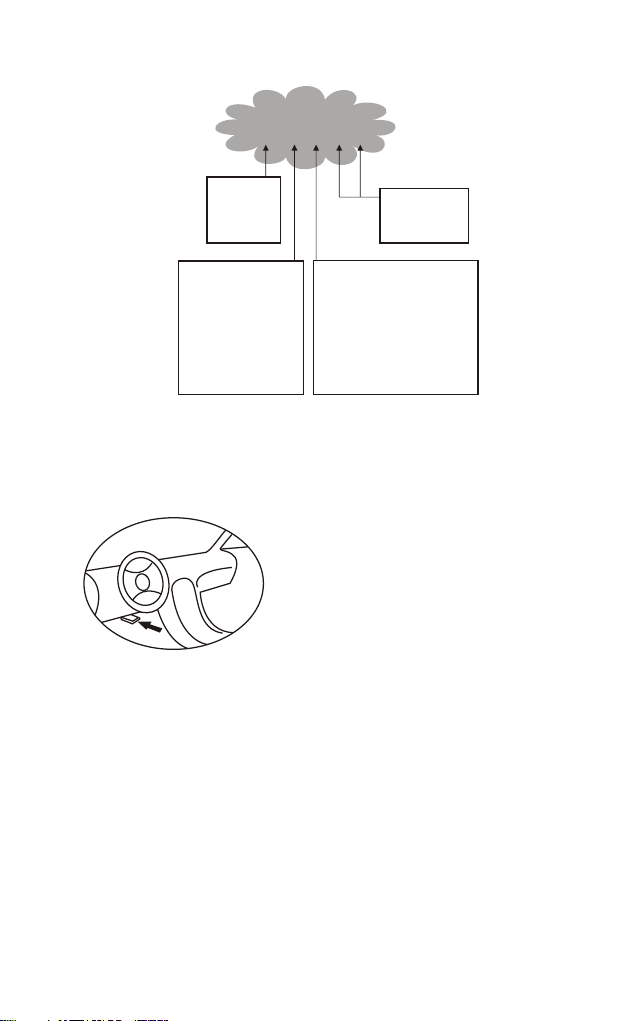
2.3 Location of the Data Link Connector (DLC)
The DLC (Data Link Connector or Diagnostic Link Connector) is the
standardized 16-cavity connector where diagnostic sacn tools interface
with the vehicle's on-board computer. The
DLC is usually located 12 inches from the
center of the instrument panel (dash),under
or around the driver's side for most
vehicles.If the Data Link Connector is not
located under the dashboard,a label should
be there indicating an alternate location. For
some Asian and European vehicles, the DLC
is located behind the ashtray, which must be removed to access the
connector. If the DLC cannot be found,refer to the vehicle's service
manual for the location.
2. 4 OBD II Readiness Monitors
An important part of a vehicle's OBD II system the Readiness Monitors.
These are indicators used to find out if all of the emissions components
have been evaluated by the OBD II system.They run periodic tests on
specific systems and components to ensure that they are performing
within allowable limits.
3

Currently, there are eleven OBD II Readiness Monitors (or I/M
Monitors) defined by the U.S. Environmental Protection Agency(EPA).
Not all monitors are supported by all vehicles and the exact number
of monitors in any vehicle depends on the motor vehicle manufacturer
and their emissions control strategy, Continuous Monitors- Some of
the vehicle components or systems are continuously tested by the
vehicles's OBD II system, while others are tested only under specific
vehicle operating conditions. The continuously monitored
components are listed below.
1) Misfire
2) Fuel System
3) Comprehensive Components (CCM)
Once the vehicle is running, the OBD II system is continuously
checking the above components, monitoring key engine sensors,
watching for engine misfire, and monitoring fuel demands.
Non-Continuous Monitors-Unlike the continuous monitors, many
emissions and engine system components require the vehicle to be
operated under specific conditions before the monitor is ready.
These monitors are termed non-continuous monitors and are listed
below:
1) EGR System
2) O2 Sensors
3) Catalyst
4) Evaporative System
5) O2 Sensor Heater
6) Secondary air
7) Heated Catalyst
8) A/C system
2.5 OBD II Monitor Readiness Status
OBD II systems must indicate whether or not the vehicle's Powertrain
Control Module (PCM) has completed testing on each component.
Components that have been tested will be reported as "Ready" or
"Complete", meaning they have been tested by OBD II system. The
purpose of recording readiness status is to allow inspectors to
determine if the vehicle's OBD II system has tested all the components
and/or systems.
The PCM sets a monitor to "Ready" or "Complete" after an appropriate
4

drive cycle has been performed. The drive cycle that enables a monitor
and sets the readiness codes to "Ready" varies for each individual
monitor. Once a monitor is set as "Ready" or "Complete",it will remain
in this state. A number of factors, including erasing of Diagnostiv
Trouble Codes(DTCs)
With a scan tool can result in Readiness Monitors being set to "Not
Ready". Since the three continuous monitors are constantly evaluating,
they will be reported as "Ready" at all times. If testing of a particular
supported non-continuous monitor has not been completed, the monitor
status will be reported as" Not Complete" or "Not Ready".
In order for the OBD monitor system to be ready, the vehicle should be
driven under a variety of normal operating conditions. These operating
conditions may include a mix of highway driving, stop-and-go city type
driving, and at least one overnight-off period. For specific informaion
on priming your vehicle's OBD monitor system,please consult your
vehicle owner's manual.
2.6 OBD II Definitions
Powertrain Control Module (PCM)—OBD II terminology for the
on-board computer that controls engine and drivetrain.
Malfunction Indicator Light (MIL)—Malfunction Indicator Light
(Service Engine Soon, Check Engine) is a term used for the light on
the instrument panel. It is to alert the driver and/or the repair
technician that there is a problem with one or more of vehicle's systems
and may cause emissions to exceed federal standards. If the MIL
illuminates with a steady light, it indicates that a problem has been
detected and the vehicle should be serviced as soon as possible. Under
certain conditions, the dashboard light will blink or fash. This indicates
a severe problem and flashing is intended to discourage vehicle
operation. The vehicle on board diagnostic system can not turn the
MIL off until the necessary repairs are completed or the condition no
longer exists.
DTC—Diagnostic Trouble Codes (DTC) are codes that identify which
section of the emission control system has malfunctioned.
Enabkubg Cruterua—Also termed Enabling Conditions. They are the
Vehicle—specific events or conditions that must occur within the engine
before the various monitors require the engine before the various
5

monitors will set, or run.Some monitors require the vehicle to follow
a prescribed "drive cycle" routine as parit of the enabling criteria.
Drive cycles vary among vehicles and for each monitor in any
particular vehicle.
OBD II Drive Cycle—A specific mode of vehicle operation that
provides conditions required to set all the applicable readiness
monitors in the vehicle to the "ready" cibdutuib. The purpose of
completing an OBD II drive cycle is to force the vehicle to run its on
board diagnostics .Some form of a drive cycle needs to be performed
after DTCs have been erased from the PCM's memory. Running
through a vehicle's complete drive cycle will "set" the readiness
monitors so that future faults can be detected. Drive cycles vary
deoending on the vehicle and the monitor that needs to be reset . For
vehicle specfic drive cycle,consult the vehicle's Owner's Manu
Freeze Frame Data—When an emissions related fault occurs,OBD II
system not only sets a code but also records a snapshot of the vehicle
operating parameter to help in identifying the proble. This set of
values is referred to as Freeze Frane Data and may include:engine
parameters such as engine PRM,vehicle speed ,air flow,engine load ,
fuel pressure,fuel trim vale,engine coolants ignition timing advance,
or colosed loop status.
3. Using the Scan Tool
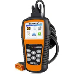
3.1 About NEXPEAK N X301
NEXPEAK NX301 Features the unique patented logical navigation
buttons, TFT backlit display screen and built-in speaker. The
NEXPEAK NX301 is the ultimate in ease and affordability, enabling
users to verify repairs, road test, check State, Emission Monitor Status
and solve engine systems and drive ability problems. The car diagnostic
functions of NX301 is much more reliable and completely superior to
other model, it support full OBDII 10 Modes diagnostics. Besides,
with built-in Memory chip, allows users to print out stored diagnostic
data via PC, and life-time free update makes you no more worry about
your car malfunction in the future.
6
3.2 Specifications
1) Display: Back lit, 128 x 64 pixel display with contrast adjustment
2) Operating Temperature: 0 to 60^(32 to 140 F° )
3) Storage Temperature:-20 to 701 (-4 to 158 F° )
4) External Power: 8.0 to 18.0 V power provided via vehicle battery
5) Dimensions:
Length Width Height
127mm(5.00") 78mm(3.07") 20mm(0.79")
6) NW:0.23kg(0.501b), GW:0.31Kg(0.68 lb)
3.3 Package Accessories
1. User Manual - Instructions on tool operations
2. OBD2 cable - Provides power to tool and communicates between
tool and vehicle
3. USB cable - Used to upgrade the scan tool, and to print retrieve
!
X
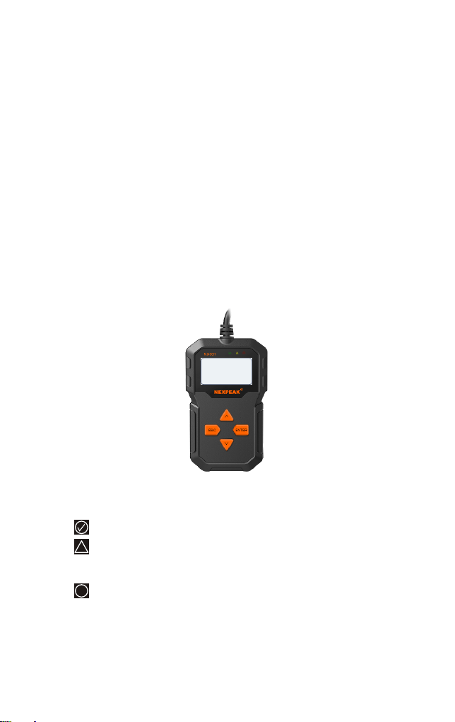
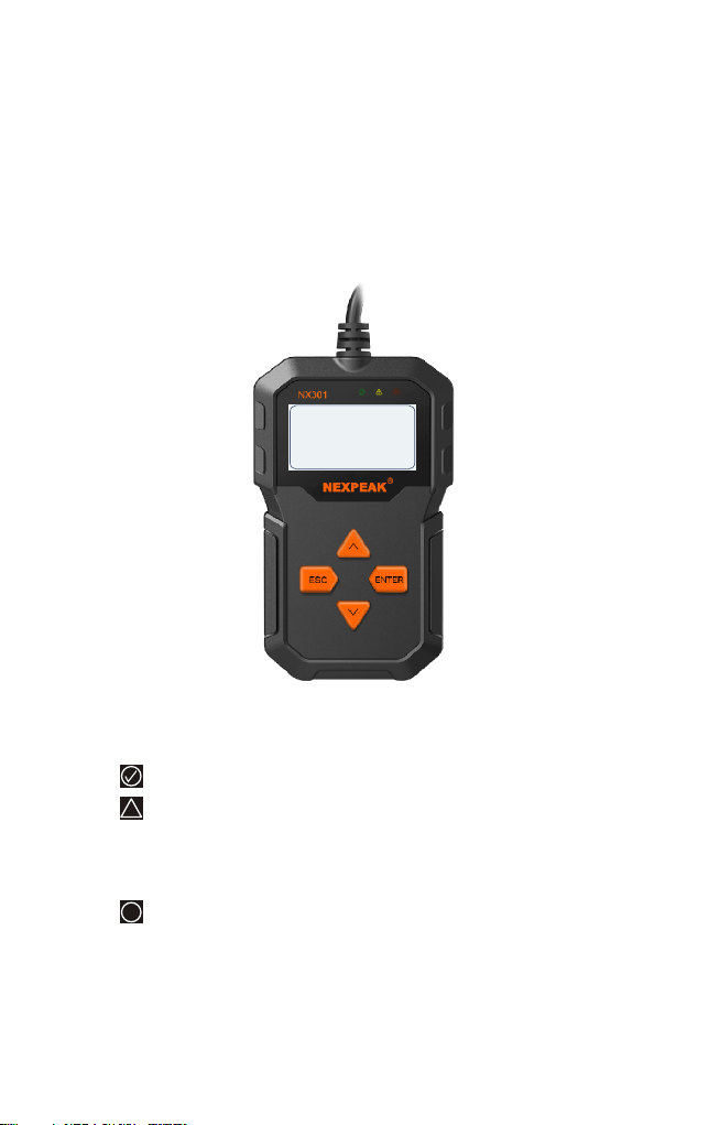
3.4 Tool Description
1) OBD IT CONNECTOR - Connects the scan tool to the vehicle's
Data Link Connector (DLC)
2) LCD DISPLAY - Displays menus and test results
3) GREEN LED - Indicates that engine systems are running
4) YELLOW LED- Indicates there is a possible problem. A
"pending" DTC is present and/or some of the vehicle's emission
monitors have not run their diagnostic testing.
5) RED LED- Indicates there is a problem in one or more of the
Vehicle's systems. The red LED is also used to show that DTCs are
present. DTCs are shown on the Scan Tool's emission monitors have
not run their diagnostic testing.
NEXPEAK
OB DII S ca nne r
N X 3 01
7
6) ESC BUTTON - Returns to previous menu.
7) ENTER BUTTON - Confirms a selection (or action) from a menu list.
8) UP SCROLL BUTTON — Moves UP through menu and sub menu
items in menu mode. When more than one screen of data is retrieved,
moves UP through the current screen to next screens for additional data.
9) DOWN SCROLL BUTTON — Moves down through menu and
sub menu items in menu mode. When more than one screen of data is
retrieved, moves down through the current screen to next screens for
additional data. It is also used as the language setup hot key when
pressed.
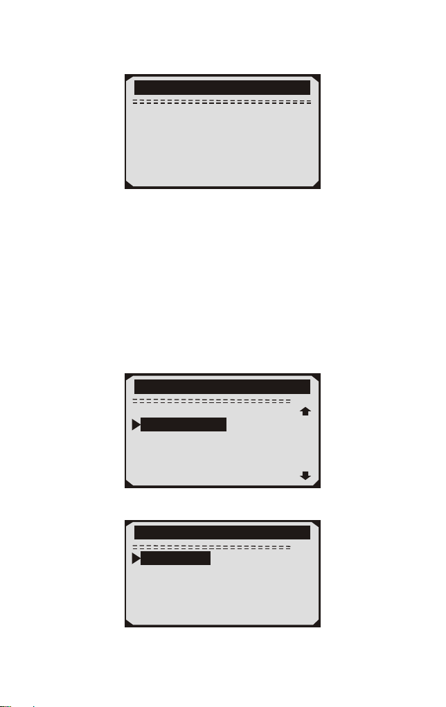
3.5 DTC Lookup
The DTC lookup function is used to search for definitions of DTCs
stored in built-in DTC library.
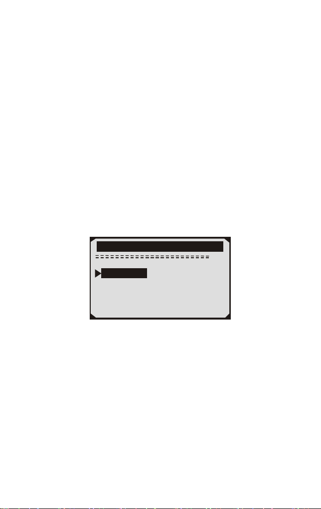
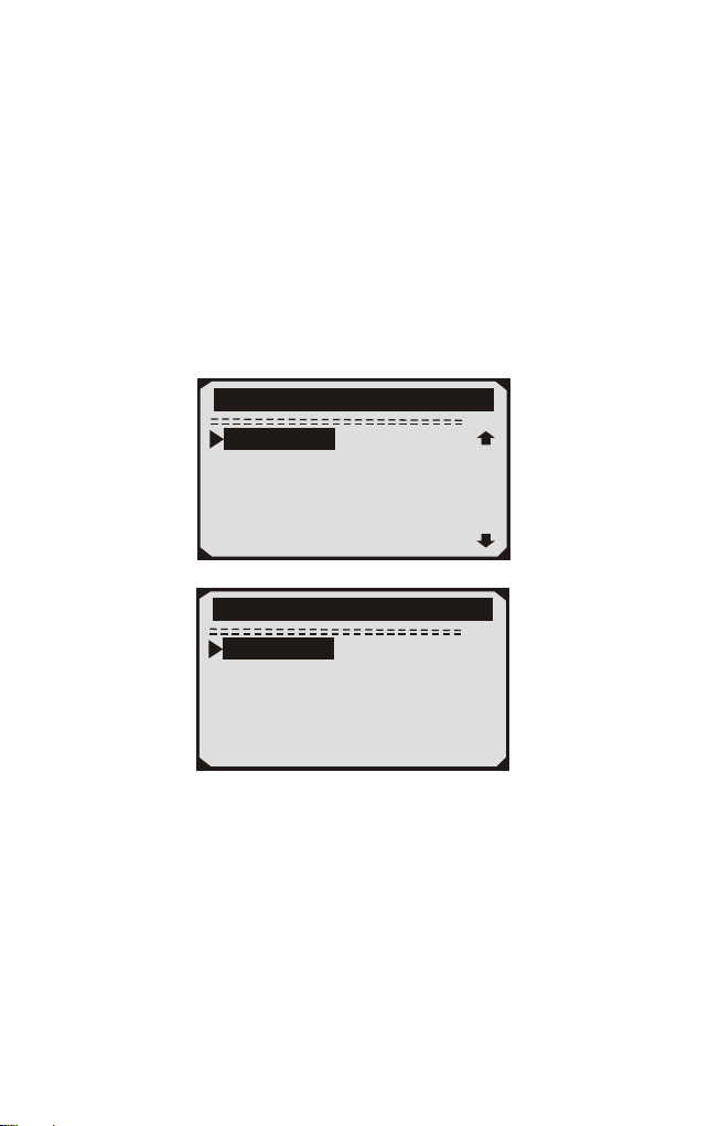
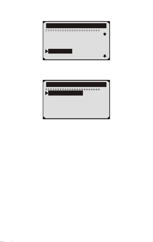
1) From the main menu,the UP/DOWN scroll button to select DTC
Lookup and press ENTER button.
2/6
Main Menu
Diagnostics
Review Data
Print Data
System Setup
Tool Information
DTC Lookup
·The number “x/x”in the top right indicates total number of items under
this menu and sequence of fighlighted item.
The “?” to the right indicates help in formation available. Press
HELP button to view help information for selected item.
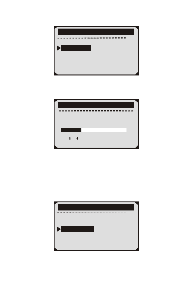
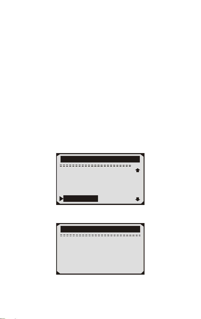
2) From DTC Lookup menu,use DOWN button to move to the desire
character,use UP button to change selected digit/charater and press
the ENTER button to confirm.
·
8

8
Main Menu
P0000
[ ]-Move to choose
[ ]-Change Digit
[ENTER]-Confirm
[ESC]-Exit
3.6 Product Setup
The scan tool allows you to adjust the following settings:
1) Language:Selects the desired language.
2) Contrast Adijustment:Adjusts the contrast of the LCD display.
3) Unit of Measurememt: Sets the unit of measure to Imperial or
Metric.
4) Auto Power-OW:Sete automatic power-off limits
5 ) Beeo Set: Turns beep on/off
6) Tool Self-Test: Checks if the LCD display and keyboard are
working normally.
Settings of the unit will remain at their default until changes to the
existing settings are made.
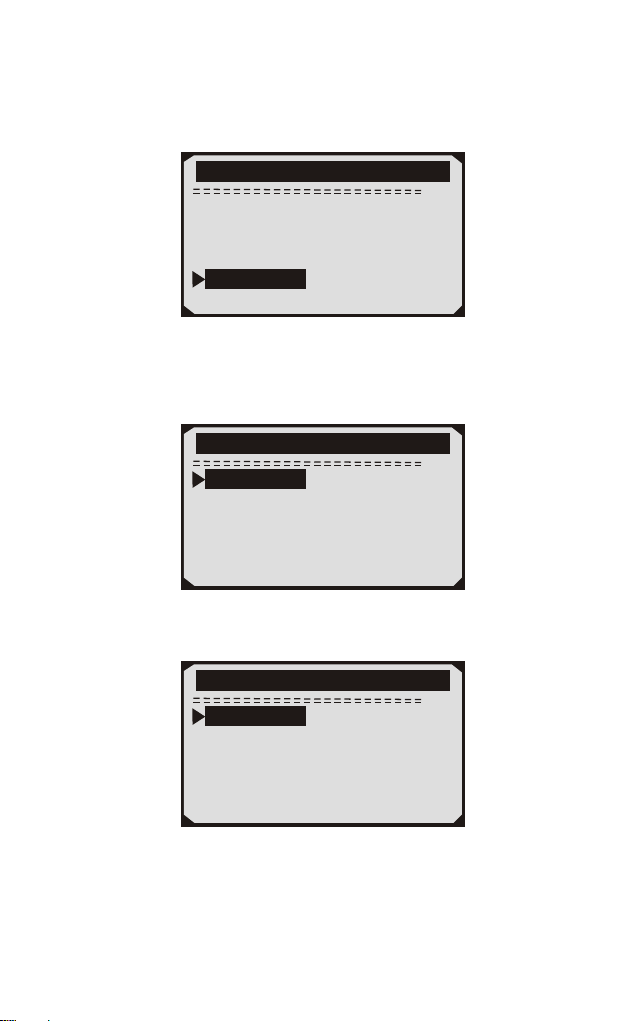
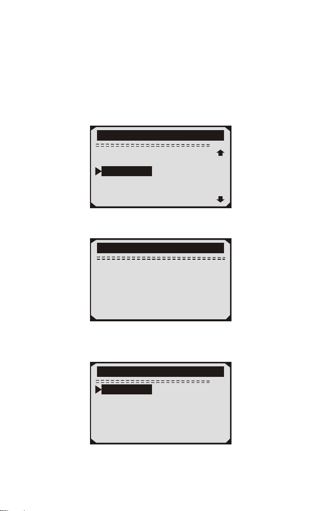
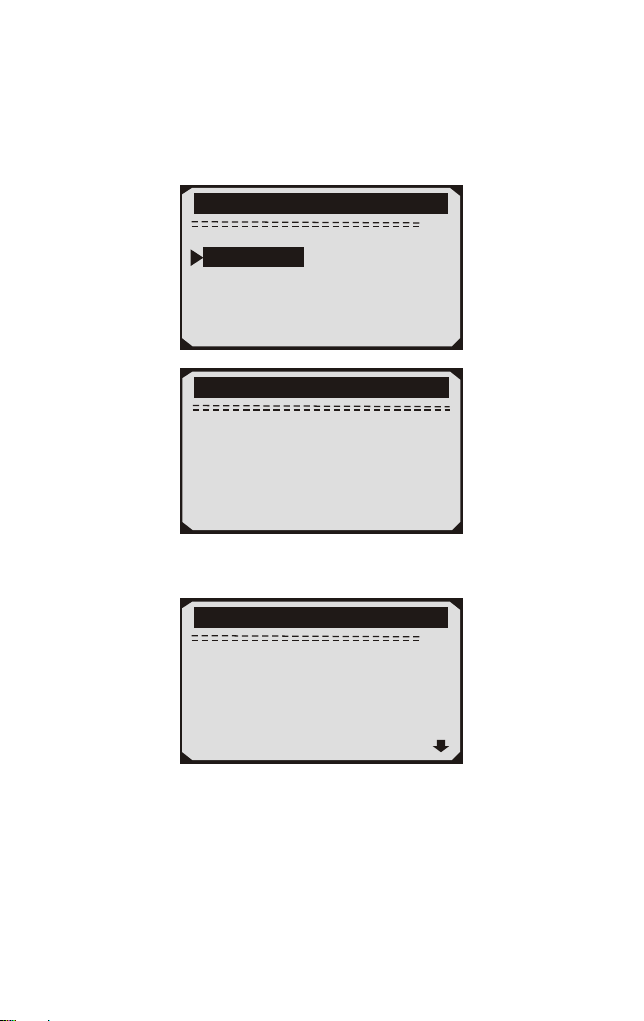
To enter the setup menu mode
From the keyboard: Press the ESC button to ener System Setup Menu.
Follow the instrucions to make adjustments and settings as described
in the following setup options.
1/6
System Setup
Language
Contrast
Unit of Measure
Auto Power-off
Beep Set
Tool Self-test
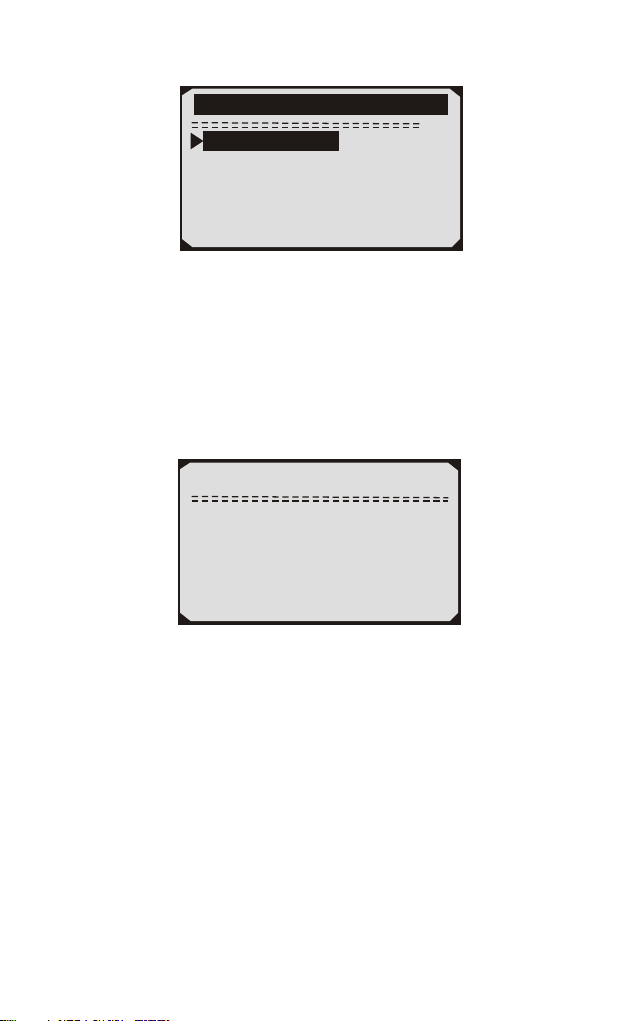
9
5/6
Main Menu
Diagnostics
DTC Lookup
Review Data
Print Data
Tool Information
System Setup
Language Setup
English is the default language.
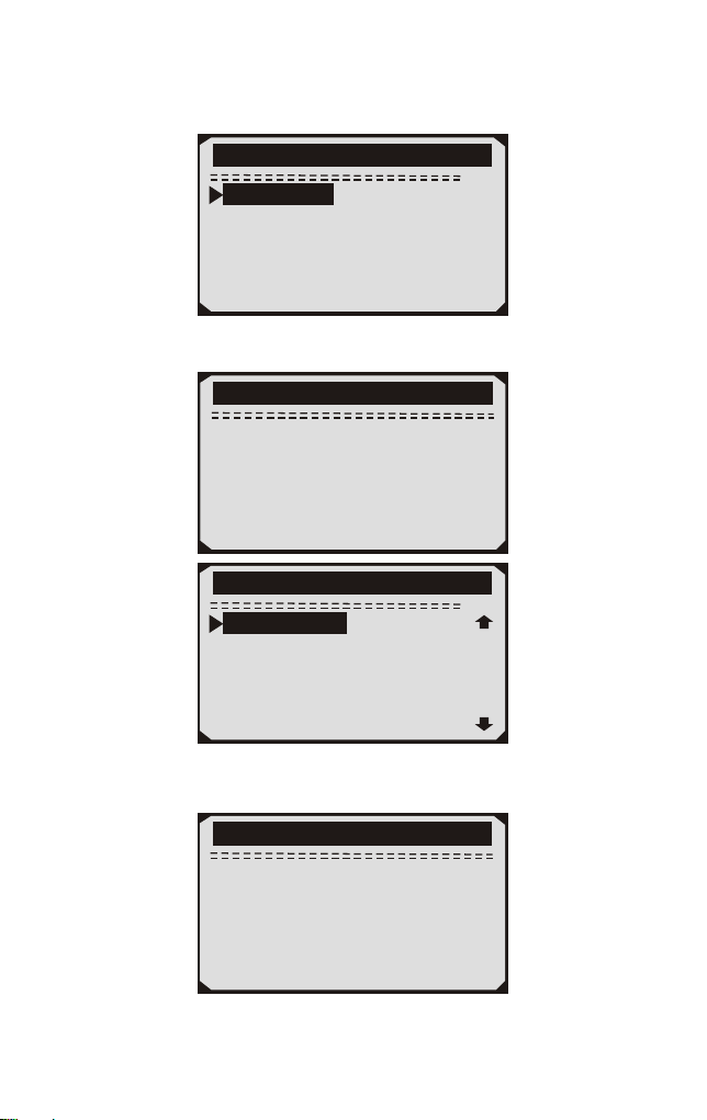
1) From the System Setup menu, use the UP/DOWN scroll button to select
Language, and press ENTER button.
1/6
System Setup
Language
Contrast
Unit of Measure
Auto Power-off
Beep Set
Tool Self-test
2) Use the UP/DOWN scroll button to select the desired langusge and
press ENTER button to save your selection and return to previous menu.
1/6
Language
English
Français
Español
Deutsch
Pусский
Dutch
Contrast Adjustment
1) From the System Setup menu, use UP/DOWN scroll button to
select Contrast, and press ENTER button.
From the Main Menu:Use the UP/DOWN scroll button to select
System Setup, and press ENTER button. Follow the instructions to
make adjustments as described in the following setup options.
10
2/6
System Setup
Contrast
Language
Unit of Measure
Auto Power-off
Beep Set
Tool Self-test
2) From Contrast menu,use the UP/DOWN scroll button to increase
or decrease contrast.
Contrast
use or to change
(30%)
3) Press the ENTER button to save your settings and return to
previous menu.
Unit of Measurement
Metric is the default measurement system.
1) From the System Setup menu, use UP/DOWN scroll button to
select Unit of Measure and press ENTER button.
3/6
System Setup
Unit of Measure
Language
Contrast
Auto Power-off
Beep Set
Tool Self-test
2) From the Unit of Measure menu,use the UP/DOWN scroll buton
to select the desired unit of measurement.
11

2/2
Unit of Measure
Metric
English
3) Press ENTER button to save your selection and return to previous
menu.
Beep Set
The default setting is been on.
1) From System Setup menu, use UP/DOWN scroll button to select
Beep Set and press the ENTER button.
5/6
System Setup
Beep Set
Language
Contrast
Unit of Measure
Auto Power-off
Tool Self-test
2) From the Beep Set menu,use the UP/DOWM scroll button to select
Beep ON or Beep OFF to turn on/off the beep.
3) Press the ENTER button to save your selection and return to
previous menu.
Tool Self-test
The Tool Self-test function checks if the display an keyboard are
working properly.
A. Display test
The Display Test funcion checks if the LCD display is working
normally.
1) From System Setup menu, use the UP/DOWN scroll button to
select Tool Self-test, and press the ENTER button.
12

6/6
System Setup
Tool Self-test
Language
Contrast
Unit of Measure
Auto Power-off
Beep Set
2) Select Display Test from Tool Self-test menu and press the
ENTER button.
1/2
Tool-Self-test
Display Test
Keyboard Test
2/2
Tool-Self-test
Keyboard Test
Display Test
3) Press the ETNER button again to start test .Look for missing spots
in the solid black characters.
4) When completed ,Press ESC button to return.
B. Keybiard Test
The Keyboard Test funcion verifies if the keys are funcioning
properly.
1) Use the UP/DOWN scroll button to seleck keyboard Test from the
Tool Self-test menu, and then press the ENTER button.
2) Press any key to start the test.When you press a key,the key name
should be observed on the display. If the key name does not show up,
then the key is not functioning properly.
13
Keyboard Test
Press any key to
start test
key:
Double [ESC] to return
·If you press and hold the power switch the key name should show up
on the screen or reset the scanner(when powered by vehicle batter). If
it does no restart the scanner or power off the scanner, the key is not
working properly.
3) Double press ESC to return to the previous menu.
3.7 Vehicles Coverage
The scan tool is specially designed to work with all OBD II compliant
vehicle's including control area network (CAN), it is required by EPA
that all 1996 and newer vehicles (Cars and light trucks) sold in the
united states must be OBD II compliant. For European car makes,
after 2001 (gasoline engine) and 2003(diesel) should be correspond
with OBD II; For Asian car makes it should be after 2005 at least.
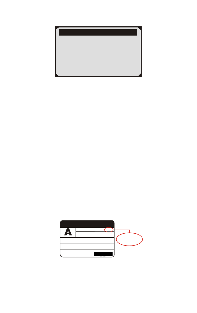
A small number of 1994 and 1995 model year gasoline vehicles are
OBDII compliant. To verify if a 1994 or 1995 vehicle is OBD II
compliant, check the vehicle emissions control information (VECI)
Label, which is located under the hood of engine or by the radiator of
most vehicles. If the vehicle is OBD II compliant, the label will
designate "OBD II Certified''. Additionally, Government regulations
mandate that all OBD II compliant vehicles must have a "common"
16 pins Data Link Connector (DLC)
VEHICLE EMISSION CONTROL INFORMATION
motor co. inc.
ENGINE FAMILY EFN2.8YBT2BA
DISPLACEMENT
2.8 L
OBD II
CER
TIFIE
D
THIS VEHICLE CONFORMS TO U.S. EPAAND STATE
OF CALIFORNIA REGULATIONS APPLICABLE TO
1997 MODEL YEAR NEW TLEV PASSENGER CARS.
REFER TO SERVICE MANUAL FOR ADDITIONAL INFORMATION
TUNE-UP CONDITIONS: NORMAL OPERATING ENGINE TEMPERATURE.
ACCESSORIES OFF,COOLING FAN OFF,TRANSMISSION IN NEUTRAL
EXHAUST EMISSIONS STANDARDS
CERTIFICATION
IN-USE
STANDARD CATEGORY
TLEV
TLEV INTERMEDIATE
SPARK PLUG
TYPE NGK BPRE-11
GAP:1.1mm
CATALYST
EFN2.8YBT2BA
00 0 0 0 0 0 0 0 0 0 0
OBD II
CERTIFIED
For the vehicle to be OBD II compliant is must have a 16-pin DLC
(Data Link Connector) under the dash and the vehicle emission control
information label must state that the vehicle is OBD II compliant.
14

4. Tool Operation
4.1 Start Diagnostics
Before using the code reader, make sure to provide power to the code
reader.The unit operates on any of the following sources:
- 12-volt vehicle power
- USB connection to personal computer.
4.1.1 Connecting to Vehicle Power
The code reader normally powers on whenever it is connected to the
data link connector (DLC).
To connect to vehicle power:
1. Locate the data link connector (DLC). The DLC is generally
located under the dash on the driver side of the vehicle.
2. Connect the code reader with the DLC.
3. Switch the ignition key to the ON position.
4. The code reader automatically boots up.
4.1.2 Connecting to Personal Computer with USB Cable
The code reader also receives power through the USB port when it is
connected to a PC for updating software and transferring saved files.
To connect to PC:
1. Insert the small end of the USB cable to the USB port at the right
side of the code reader and the large end to a computer.
2. Press the power switch of the code reader to power it on.
4.2 Read Codes
Read Codes menu lets you read stored codes, pending codes and
permanent codes found in the control unit. Typical menu options
include:
Stored Codes: Diagnostic trouble codes stored in a control module
are used to help identify the cause of a trouble or troubles with a
vehicle. These codes have occurred a specific number of times and
indicate a problem that requires repair.
•
15
• Pending Codes: Pending codes are referred to as maturing codes
that indicate intermittent faults. If the fault does not occur within a
certain number of drive cycles (depending on vehicle), the code clears
from memory. If a fault occurs a specific number of times, the code
matures into a DTC and the MIL illuminates or blinks.
To read codes from vehicle:
1) Use UP/DOWN scroll button to select Read Codes from
Diagnostic Menu and press ENTER button.
2) Use UP/DOWN scroll button to select Stored Codes or Pending
Codes form the Trouble Codes menu and press ENTER button.
1/11
Diagnostic Menu
Read Codes
Erase Codes
Live Data
View Freeze Frame
I/M Readiness
O2 Monitor Test
1/2
Trouble Codes
Srored Codes
Pending Codes
• If there are no Diagnostic Trouble Codes present, the display
indicates "No (pending) codes are stored in the module!" Wait a few
seconds or press any key to return to Diagnostic Menu.
3) View DTCs and their definitions on screen.
16

P0118
S09
Generic
1/5
Engine Coolant Temperature
Sensor 1 Circuit High
Note: If no DTCs are present, the message "No (Pending) Codes
Found!" is displayed. If any manufacturer specific or enhanced
codes detected, NX301 reads the correct DTC information
automatically according to the VIN.
4.3 Erase Codes
CAUTION:
1.To clear codes, make sure that the ignition key is switched to ON
with the engine off.
2. Erase codes does not fix the problem that caused the fault! DTCs
should only be erased after correcting the condition(s) that caused
them by a technician.
To clear codes:
1) Use UP/DOWN scroll buttons to select Erase Codes from
Diagnostics Menu and press ENTER button.
2/11
Diagnostic Menu
Read Codes
Live Data
View Freeze Frame
I/M Readiness
O2 Monitor Test
Erase Codes
17

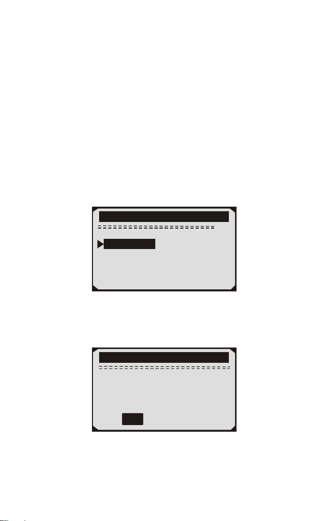
2) A warning message comes up asking for your confirmation.
Erase Codes
Erase trouble codes!
Are you Sure?
YES NO
3) Press ENTER button to confirm.
If the codes are cleared successfully, an "Erase Done!" confirmation
message shows on the display.
•
Erase Codes
Erase Done!
Press any key to con.
• If the codes are not cleared, then an "Erase Failure. Turn Key on
with Engine off!" message appears.
Erase Codes
Erase Failure
Turn Key on with
Engine Off!
Press any key to con.
4) Press any button to return to Diagnostic Menu
18
4.4 Live Data
4.4.1 View Data
The View Data function allows viewing of live or real time PID data
of vehicle's computer module(S).
1) To view live data, use UP/DOWN scroll button to select Live
Data from Diagnostic Menu and press ENTER button.
3/11
Diagnostic Menu
Read Codes
Erase Codes
View Freeze Frame
I/M Readiness
O2 Monitor Test
Live Data
2) Wait a few seconds while the scan tool validates the PID MAP.
Live Data
Reading PID.01
-Please Wait-
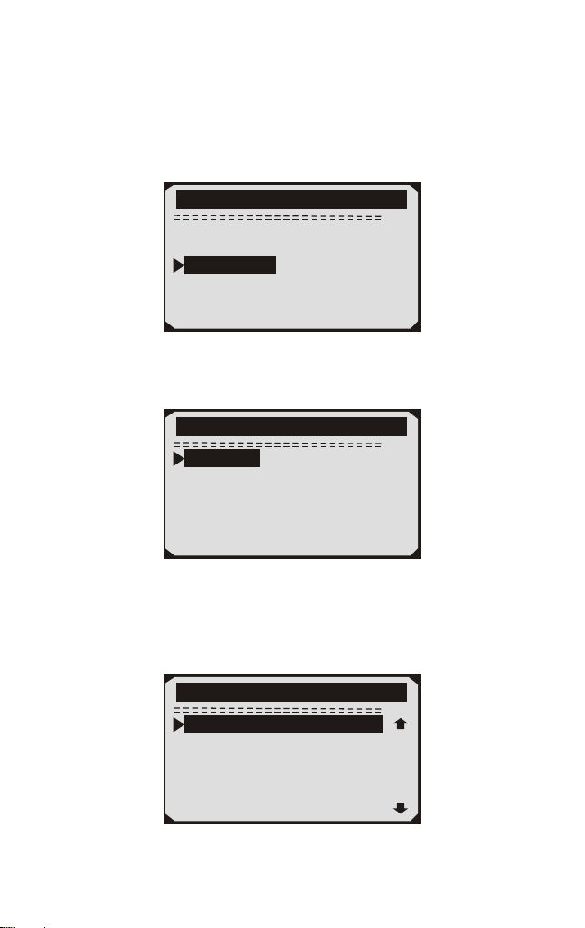
3) Use UP/DOWN scroll button to select View Data from Live Data
menu and press ENTER button.
1/3
Live Data
View Data
Record Data
Playback Data
19
Viewing Complete Data Set
4) To view complete set of data, use UP/DOWN scroll button to select
Complete Data Set from View Data menu and press ENTER button.
5) View live PIDs on the screen. Use UP/DOWN scroll button for
more PIDs if an UP or DOWN arrow appears on the screen.
1/84
Live Data
DTC_CNT 0
DTCFRZF P0000
FUEL SYS1 CL
FUEL SYS2 CL
LOAD_PCT(%) 0.0
ECT( F) 417
。
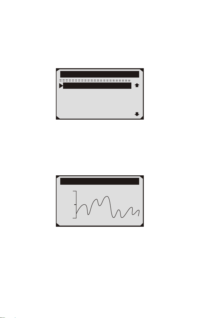
* The number "x" to the right of the screen indicates sequence of
highlighted item.
* If you want to view full name of the highlighted PID, press Help
button.
If the icon appears when a PID is highlighted, it indicates graphic
information is available. Press ENTER to view graph.
*
RPM(/min) 975
1725
925
6) Press ESC button to return to previous menu.
* You are allowed to pick up a maximum of 18 PIDs, if the selected
PIDs exceed 18, a "The selected data list is full!" message displays
on the screen.
20
4.4.2 Record Data
The Record Data function allows recording vehicle modules'
Parameter Identification (FID) data to help diagnose intermittent
vehicle problems. A recording includes 5 frames of live data before
trigger event and several frames after trigger event.
There are two trigger modes used to record data:
A. Manual Trigger - allows user to press ENTER button to start
recording.
B. DTC Trigger - automatically records PID data when a fault that
causes a DTC to set is detected by vehicle.
:
CAUTON DO NOT try to drive and operate the scan tool at the same
time! Always have another person operate the scan tool while driving.
2/3
Live Data
View Data
Playback Data
Record Data
The scan tool keeps recording PID data until user presses ESC button,
selected memory location is full, or it completes recording. A message
prompting to playback data shows on the screen.
Record Data
Record Done!
Playback data?
YES NO
21
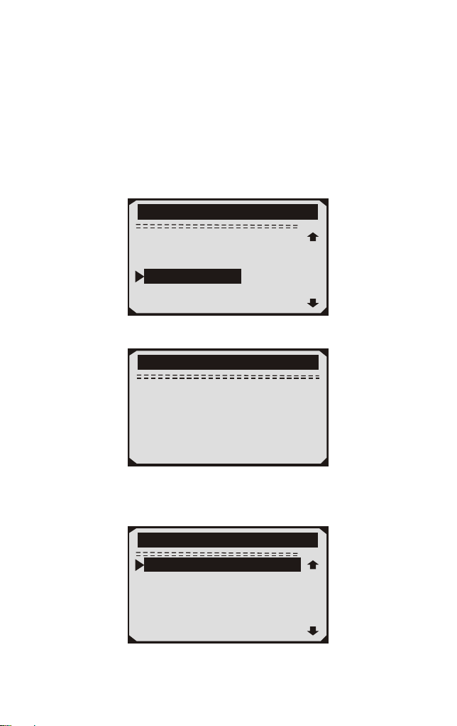
4.4.3 Playback Data
The Playback Data function allows viewing of previously stored PID data.
1) To playback recorded data, use UP/DOWN scroll button to select
Playback Data from Live Data menu and press RNTER button.
3/3
Live Data
View Data
Record Data
Playback Data
You are also allowed to playback recorded data immediately after
recording.
2) Use UP/DOWN button to select the memory location marked
with an asterisk (*) icon.
1/6
Review Data
Location #1
Location #2
Location #3
Location #4
Location #5
Location #6
If there is no recording in selected location, a message "Not
Supported or Stored No Data" displays on the screen.
For data stored in temporary cache, you do not have to select
memory location.
3) Use UP/DOWN button to view recorded PIDs of each frame.
Use ENTER to convert pages or rows.
•
•
1/312
Playback Data
DTC CNT 2_
FUELSYS1 CL
FUELSYS2 CL
LOAD_PCT(%) 0.0
SHRTFT1(%) 48. 4
DTC_CNT 2
22
The number "x/x" to the upper right comer of the screen indicates
total number of recorded frames and sequence of frame being displayed.
Negative frames indicate data recorded prior to trigger event, and
positive frames indicate data recorded after trigger event.
4.5 View Freeze Frame Data
1) To view freeze frame data, use UP/DOWN scroll button to select
View Freeze Frame from Diagnostic Menu and press ENTER button.
•
•
4/11
Diagnostic Menu
Read Codes
Erase Codes
Live Data
I/M Readiness
O2 Monitor Test
View Freeze Frame
2) Wait a few seconds while the scan tool validates the PID MAP.
View Freeze Frame
Reading PID.01
-Please Wait-
3) If retrieved in formation covers more than open screen, then a
down arrow will appear. Use DOWN scroll button, as necessary,
until all the data have been shown up.
1/8
View Freeze Fram
DTCFRZF B0090
LOAD_PCT(%) 0.0
ETC( F) 417
NAP(inH9) 76.2
RPM(/min) 12210
VSS(mph) 157
23

• If there is no freeze frame data available, an advisory message "No
freeze frame data stored!" shows on the display.
4) If you want to view full name of a PID, use UP/DOWN scroll
button to select the PID, and press HELP button.
ECT
Engine Coolant
Temperaturee
5) Wait a few seconds of press any button to return to previous screen.
4.6 Retrieve I/M Readiness Status
I/M Readiness function is used to check the operations of the
Emission System on OBD2 compliant vehicles. It is an excellent
function to use prior to having a vehicle inspected for compliance to
a state emissions program.
Some latest vehicle models may support two types of I/M Readiness
tests:
A. DTCs Cleared - indicates status of the monitors since the DTCs
are erased.
B. This Drive Cycle — indicates status of monitors since the
beginning of the current drive cycle.
An I/M Readiness Status result of "NO" does not necessarily indicate
that the vehicle being tested will fail the state I/M inspection. For some
states, one or more such monitors may be allowed to be "Not Ready"
to pass the emissions inspection.
"OK" —— Indicates that a particular monitor being checked has
completed its diagnostic testing.
"INC" — Indicates that a particular monitor being checked has not
completed its diagnostic testing.
"N/A" ——The monitor is not supported on that vehicle.
1) Use UP/DOWN scroll button to select I/M Readiness from
Diagnostic Menu and press ENTER button.
24
1/2
I/M Readiness
Since DTCs Cleared
This Drive Cycle
5/11
Diagnostic Menu
Read Codes
Erase Codes
View Freeze Frame
O2 Monitor Test
Live Data
I/M Readiness
2) If the vehicle supports both types of tests, then both types will be
shown on the screen for selection.
3) Use UP/DOWN scroll button, as necessary, to view the status of
the MIL light ("ON" or "OFF") and the following monitors:
Misfire monitor — Misfire monitor
Fuel System Mon — Fuel System Monitor
Comp. Component — Comprehensive Components Monitor
EGR — EGR System Monitor
Oxygen Sens Mon — 02 Sensors Monitor
Catalyst Mon — Catalyst Monitor
EVAP System Mon — Evaporative System Monitor
Oxygen Sen htr — Oxygen Sensor Heater Monitor
Sec Air System — Secondary Air Monitor
Htd Catalyst — Heated Catalyst Monitor
A/C Refrig Mon — A/C system Monitor 4) Press ESC button to
return to Diagnostic Menu.
•
•
•
•
•
•
•
•
•
•
•
25
4.7 Oxygen(O2) Sensor Monitor Test
OBD2 regulations set by SAE require that relevant vehicles monitor
and test the oxygen (O2) sensors to identify problems related to fuel
efficiency and vehicle emissions. These tests are not on-demand tests
and they are done automatically when engine operating conditions are
within specified limits. These test results are saved in the on-board
computer's memory.
The O2 Monitor Test function allows retrieval and viewing of O2
sensor monitor test results for the most recently performed tests from
the vehicle's on-board computer.
The O2 Monitor Test function is not supported by vehicles which
communicate using a controller area network (CAN), For O2
Monitor Test results of CAN-equipped vehicles, see chapter
"On-Board Mon. Test".
1) Use UP/DOWN scroll button to select O2 Monitor Test from
Diagnostic Menu and press ENTER button.
6/11
Diagnostic Menu
Read Codes
Erase Codes
View Freeze Frame
I/M Readiness
Live Data
O2 Monitor Test
2) Wait a few seconds while the scan tool validates the PID MAP.
O2 Monitor Test
Reading PID...
-Please Wait-
26
3) Use UP/DOWN scroll button to select O2 sensor from O2 Monitor
Test menu and press ENTER button.
If the vehicle does not support the mode, an advisory message will be
displayed on the screen.
2/2
O2 Monitor Test
02 Mon.B1S1
02 Mon.B1S2
O2 Monitor Test
The selected mode is
not supported
Press any key to con.
4) View test results of selected O2 sensor.
1/3
O2 Mon. B1S2
Rich to lean
sensor(V)
MEAS: 6.9939(V)
MIN: 3.9352(V)
MAX: 4.8097(V)
STS: Fall
5) Use UP/DOWN scroll button to view more screens of data if an
UP or DOWN icon displays.
6) Press ESC button to return to the previous menus.
27

4.8 On-Board Monitor Test
The On-Board Monitor Test is useful after servicing of after erasing
a vehicle's control module memory. The On-Board Monitor Test for
non-CAN-equipped vehicles retrieves and displays test results for
emission-related power train components and systems that are not
continuously monitored. The On-Board Monitor Test for
CAN-equipped vehicles retrieves and displays test results for
emission-related power train components and systems that are and
are not continuously monitored. Test and components IDs arc
determined by the vehicle manufacturer.
1) Use UP/DOWN scroll button to select On-Board Mon. Test from
Diagnostic Menu and press ENTER button.
7/11
Diagnostic Menu
On-Board Mon. Test
Component Test
Vehicle Info
Modules Present
Unit of Measure
2) Wait a few seconds while the scan tool validates the PID MAP.
On-Board Mon.Test
Reading PID...
-Please Wait-
28
3) From On-Board Mon. Test menu, use UP/DOWN scroll button to
select a test to view and press ENTER button.
1/3
On-Board Mon.Test
Test S01 Data
Test S05 Data
Test S09 Data
If the vehicle under test does not support the mode,an advisory
message will be displaye on the screen.
On-Board Mon.Test
The selected mode is
not supported
Press any key to con.
1/4
On-Board Mon.Test
Catalyst Mon.B1
02 Heater Mon.B1S1
02 Heater Mon.B1S2
Heated Catalyst B1
4) Use UP/DOWN scroll button to select the desired monitor from
On-Board Mon. Test menu and press ENTER button.
5) View test data on screen.
Catalyst Mon.B1
Lean to rich
sensor(V)
MEAS: 6.0540(V)
MIN: 3.4071(V)
MAX: 4.1642(V)
STS: Fall
29
For CAN-equipped vehicles, test results displayed can be as below:
02 Heater Mon. B1-S1
SOD TEST
MEAS: 10.180(V)
MIN: 10.500(V)
MAX: 13.800(V)
STS: Fall
6) Press ESC button to return to the previous menus.
4.9 Component Test
The Component Test function allows initiating a leak test for the
vehicle's EVAP system. The scan tool itself does not perform the leak
test, but commands the vehicle's on-board computer to start the test.
Different vehicle manufacturers might have different criteria and
methods for stopping the test once it has been started. Before starting
the Component Test, refer to the vehicle service manual for
instructions to stop the test.
1) Use UP/DOWN scroll button to select Component Test from
Diagnostic Menu and press ENTER button.
8/11
Diagnostic Menu
On-Board Mon. Test
Vehicle Info
Modules Present
Unit of Measure
Component Test
2) From Component Test menu, use UP/DOWN scroll button to
select the test to be initiated.
1/1
Compenent Test
EvpLeak Test
30

3) If the test has been initiated by the vehicle, a confirmation
message will be displayed on the screen.
Working
Command Sent!
Pree any key to con.
Some vehicles do not allow scan tools to control vehicle systems or
components. If the vehicle under test does not support the EVAP
Leak Test, an advisory message is displayed on the screen.
Component Test
The selected mode is
not supported
Pree any key to con.
4) Wait a few seconds or press any key to return to Diagnostic Menu.
4.10 Viewing Vehicle Information
The Vehicle Info, function enables retrieval of Vehicle Identification
No. (VIN), Calibration ID(s), Calibration Verification No. (CVN)
and In-use Performance Tracking on 2000 and newer vehicles that
support Mode 9.
1) Use UP/DOWN scroll button to select Vehicle Info, from the
Diagnostic Menu and press ENTER button.
9/11
Diagnostic Menu
On-Board Mon. Test
Component Test
Modules Present
Unit of Measure
Vehicle Info
31

2) Wait a few seconds while the scan tool reads vehicle information.
Reading PID...
-Please Wait-
Vehicle Info.
3) View retrieved vehicle information on screen.
1/5
Vehicle Info
VIN:161JC544R7252367
CID1:JMB*36761500
CID2:JMB*4787261111
CIN1:1791BC82
CIN2:16E062BE
4) Press ESC button to return previous menu
4.11 LED Interpretation
1) GREEN LED -- indicates the engine system is working normally
(all monitors on the vehicle are active and performing their diagnostic
testing), and no DTCs are found.
2) YELLOW LED -- shows the tool finds a possible problem.
Pending DTCs exist or/and some of the vehicle's emission monitors
have not run their diagnostic testing.
3) RED LED –indicates there are some problems in one or more of
the vehicle's systems. In this case, the MIL lamp on the instrument
panel is on.
A. Repair the vehicle yourself. If you are going to perform the repairs
yourself, proceed by reading the vehicle service manual and following
all its procedures and recommendations.
B. Take the vehicle to a professional to have it serviced. The
problem(s) causing the red LED to light must be repaired before the
vehicle is ready for is ready for an Emissions Test.
32

5. Printing Diagnostic Report
The Print Data function allows uploading the recorded data by scan
tool to windows PC for printing out (Needs Windows PC connecting
with printers), you may customized the data/report before printing
on computers.
To upload the recorded data, you need the following tools:
1.Scan tool
2.A Windows PC or laptop with USB ports. (Support only official
version windows XP-10, 32/64 Bits OS)
3.A USB cable
Steps:
Download and install the applications from official website:
on windows computer.
* Please turn off anti-virus software if warning message showing up,
otherwise the driver may not be installed properly
Please ignore the Microsoft Modem drivers install failure if you
are not using windows XP system.
2) Connect the scanner to computer with the USB cable supplied.
3) Run the UPLINK.exe in your PC.
4) Use the UP/DOWN scroll button to select Print Data from Main
Menu in the scan tool, and press the OK button.
5) Use the UP/DOWN scroll button to select the desired item to
print from Print Data menu.
To print all retrieved data, use the UP/DOWN scroll button to select
Print All Data from Print Data menu.
6) Press the OK button to upload data to the computer.
7) In the UPLINK.exe Tool Kit, you could edit, delete, copy and
print the data in the text box by selecting the icons on the upper
right of window.
NOTE: Data stored in a language different from current system
settings of the scan tool will not be printable, please adjust language
settings before printing. A reminder would pop up under such
circumstances.
1)
*
www.nexpeaktech.com
6. Update the Scan Tool
This function allows you to update the scan tool software and DTC
library through a Windows computer
33
34
To update your scan tool, you need the following items.
1.Scan tool
2.A PC or laptop with USB ports. (Support only official version
windows XP-10, 32/64 Bits OS)
3.USB cable
Steps:
1) Download and install the applications from our website:
www.nexpeaktech.com
2) Run UPLINK.exe in your computer (Mac OS does not compatible)
3) Press and hold any button until the USB cable is connected with
computer and Release it after the scan tool displays a message
"Update Mode"
4) Return to the UPLINK software, click" Check update" button, will
download the upgrade file from internet then update to scan tool
automatically.
5) Wait for few minutes until update succeed.
6) During the update procedure, please do not disconnect the usb
connection.
7) Restart the scan tool to finish the whole update.
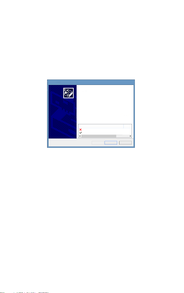
Please ignore the Microsoft Modem drivers install failure if you are not using windows XP system.
Device Driver Installation Wizard
Completing the Device Driver
Installation Wizard
Some drivers were successfully installed on this computer.Some
could not be installed.See the Status column for more details.
if a device came with your software,you can now connect it to this
computer.
For devices where no driver was installed.contact your device
vendor.
Drvier Name
Status
Microsoft Modem (06/21/2006 6.1.7601.17514) Install fai
STMicroelectronics (usbser) Ports (04/25/2010... Ready to
< Back
Finish
Cancel
NOTE: When you made a wrong choice and the scan tool is unable to
work properly, you may need to update the programs. To hold LEFT
scroll button and power on the scan tool, you will enter the update
mode forcedly. Then follow the update procedure to refresh the
program.

7. Appendix
7.1 Appendix 1-PID List
PID Abbreviation
Full Name
DTC_CNT
DTCFRZF
FUELSYS1
FUELSYS2
LOAD_PCT(%)
ECT( F)
ETC( C)
SHRTFT1(%)
SHRTFT3(%)
LONGFT1(%)
LONGFT3(%)
SHRTFT2(%)
SHRTFT4(%)
LONGFT2(%)
LONGFT4(%)
FRP(kPa)
FRP(psi)
MAP(kPa)
MAP(inHg)
RPM(/min)
VSS(km/h)
VSS(mph)
SPARKADV(\x82)
IAT( F)
IAT( C)
MAF(g/s)
MAF(1b/min)
TP(%)
。
。
。
。
DTC Stored Number
DTC
Fuel System 1 Status
Fuel System 2 Status
Calculated Load Value
Engine Coolant Temperature
Engine Coolant Temperature
Short Term Fuel Trim-Bank1
Short Term Fuel Trim-Bank3
Long Term Fuel Trim-Bank1
Long Term Fuel Trim-Bank3
Short Term Fuel Trim-Bank2
Short Term Fuel Trim -Bank4
Long Term Fuel Trim-Bank2
Long Term Fuel Trim-Bank4
Fuel Rail Pressure(gauge)
Fuel Rail Pressure(gauge)
Intake Manifold Absolut Pressure
Intake Manifold Absolut Pressure
Engine RPM
Vehicle Speed Sensor
Vehicle Speed Sensor
Ignition Timing Advance for #1
Intake Air Temperature
Intake Air Temperature
Mass Air Flow Sensor
Mass Air Flow Sensor
Absolut Throttle Position
35

PID Abbreviation
Full Name
AIR-STAT
O2SLOC
O2B1S1(V)
SHRTFTB1S1(%)
O2B1S2(V)
SHRTFTB1S2(%)
O2B1S3(V)
SHRTFTB1S3(%)
O2B1S4(V)
SHRTFTB1S4(%)
O2B2S1(V)
SHRTFTB2S1(%)
O2B2S2(V)
SHRTFTB21S2(%)
O2B2S3(V)
SHRTFTB2S3 (%)
O2B2S4(V)
SHRTFTB21S4(%)
O2B1S1(V)
SHRTFTB1S1(%)
O2B1S2(V)
SHRTFTB1S2(%)
O2B2S1(V)
SHRTFTB2S1(%)
O2B2S2(V)
SHRTFTB2S2(%)
O2B3S1(V)
SHRTFTB3S1(%)
O2B3S2(V)
SHRTFTB3S2(%)
O2B4S1(V)
Commanded Secondary Air Status
Location of O2 Sensors
O2 Sensor Output Voltage(B1S1)
Short Term Fuel Trim(B1S1)
O2 Sensor Output Voltage(B1S2)
Short Term Fuel Trim(B1S2)
O2 Sensor Output Voltage(B1S3)
Short Term Fuel Trim(B1S3)
O2 Sensor Output Voltage(B1S4)
Short Term Fuel Trim(B1S4)
O2 Sensor Output Voltage(B2S2)
Short Term Fuel Trim(B2S2)
O2 Sensor Output Valtage(B2S3)
Short Term Fuel Trim(B2S3)
O2 Sensor Output Voltage(B2S4)
Short Term Fuel Trim(B2S4)
O2 Sensor Output Voltage(B2S1)
Short Term Fuel Trim(B2S1)
O2 Sensor Output Voltage(B1S2)
Short Term Fuel Trim(B1S2)
O2 Sensor Output Voltage(B2S1)
Short Term Fuel Trim(B2S1)
O2 Sensor Output Voltage(B2S2)
Short Term Fuel Trim(B2S2)
O2 Sensor Output Voltage(B3S1)
Short Term Fuel Frim(B3S1)
O2 Sensor Output Voltage(B3S2)
Short Term Fuel Trim(B3S2)
O2 Sensor Output Voltage(B4S1)
O2 Sensor Output Voltage(B2S1)
Short Term Fuel Trim(B2S1)
36

PID Abbreviation
Full Name
SHRTFTB4S1(%)
O2B4S2(V)
SHRTFRB4S2(%)
OBDSUP
O2SLOC
RUNTM(sec)
MIL_DIST(km)
FRP(kpa)
FRP(PSI)
FRP(kpa)
FRP(PSI)
EQ_RATB1S1
O2B1S2(V)
EQ_RARB1S2
O2B1S2(V)
EQ_RATB1S3
O2B1S3(V)
EQ_RATB1S4
O2B1S4(V)
EQ_RATB2S1
O2B2S1(V)
EQ_RATB2S2
O2B2S2(V)
EQ_RATB2S3
O2B2S3(V)
EQ_RATB2S4
O2B2S4(V)
EQ_RATB1S1
O2B1S1(V)
EQ_RATB1S2
O2B1S2(V)
MIL_DIST(milc)
Short Term Fuel Trim(B4S1)
O2 Sensor Output Voltage(B4S2)
Short Term Fuel Trim(B4S2)
OBD Require To Whic Vehicle Designed
Location Of O2 Sensors
Time Since Engine Start
Distance Travelled While MIL Activated
Distance Travelled While MIL Activated
FuelRail Pres. Relative To Manifold Vacuum
FuelRail Pres. Relative To Manifold Vacuum
Fuel Rail Pressure
Fuel Rail Pressure
Equivalence Ratio(wide range O2S)(B1S1)
O2 Sensor Voltage(wide range O2S)(B1S1)
Equivalence Ratio(wide range O2S)(B1S2)
O2 Sensor Voltage(wide range O2S)(B1S2)
Equivalence Ratio(wide range O2S)(B1S3)
O2 Sensor Voltage(wide range O2S)(B1S3)
Equivalence Ratio(wide range O2S)(B1S4)
O2 Sensor Voltage(wide range O2S)(B1S4)
Equivalence Ratio(wide range O2S)(B2S1)
O2 Sensor Voltage(wide range O2S)(B2S1)
Equivalence Ratio(wide range O2S)(B2S2)
O2 Sensor Voltage(wide range O2S)(B2S2)
Equivalence Ratio(wide range O2S)(B2S3)
O2 Sensor Voltage(wide range O2S)(B2S3)
Equivalence Ratio(wide range O2S)(B2S4)
O2 Sensor Voltage(wide range O2S)(B2S4)
Equivalence Ratio(wide range O2S)(B2S1)
O2 Sensor Voltage(wide range O2S)(B2S1)
Equivalence Ratio(wide range O2S)(B1S2)
O2 Sensor Voltage(wide range O2S)(B1S2)
37

PID Abbreviation
Full Name
EQ_ RATB2S1
O2B2S1(V)
EQ_RATB2S2
O2B2S2(V)
EQ_RATB3S1
O2B3S1(V)
EQ_RATB3S2
O2B3S2(V)
EQ-RATB4S1
O2B4S1(V)
EQ_RATB4S2
O2B4S2(V)
EGR_PRC(%)
EGR_ERR(%)
EVAP_PCT(%)
FLI(%)
WARM_UPS
LCR_DIST(km)
CLR_DIST(mile)
EVAP_VP(Pa)
EVAP_VP(inH2O)
BARO(kPa)
BARO(inHg)
EQ_ART11
O2S11(mA)
EQ_RAT13
O2S13(mA)
EQ_RAT14
O2S14(mA)
EQ_RAT21
EQ_RAT12
O2S12(mA)
Equivalence Ratio(wide range O2S)(B2S1)
O2 Sensor Voltage(wide range O2S)(B2S1)
Equivalence Ratio(wide range O2S)(B2S2)
O2 Sensor Voltage(wide range O2S)(B2S2)
Equivalence Ratio(wide range O2S)(B3S1)
O2 Sensor Voltage(wide range O2S)(B3S1)
Equivalence Ratio(wide range O2S)(B3S2)
O2 Sensor Voltage(wide range O2S)(B3S2)
Equivalence Ratio(wide range O2S)(B4S1)
O2 Sensor Voltage(wide range O2S)(B4S1)
Equivalence Ratio(wide range O2S)(B4S2)
O2 Sensor Voltage(wide range O2S)(B4S2)
Commanded EGR
EGR Error
Commanded Evaporative Purge
Fuel Level Input
Number of Warm-ips Since DTC Cleared
Distance Since DTC Cleared
Distance Since DTC Cleared
Evap System Vapor Pressure
Evap System Vpor Pressure
Barometric Pressure
Barometric Pressure
Equivalence Ratio(wide range O2S)(B1S1)
O2 Sensor Current(wide range O2S)(B1S1)
Equivalence Ratio(wide range O2S)(B1S2)
O2 Sensor Current(wide range O2S)(B1S2)
Equivalence Ratio(wide range O2S)(B1S3)
O2 Sensor Current(wide range O2S)(B1S3)
Equivalence Ratio(wide range O2S)(B1S4)
O2 Sensor Current(wide range O2S)(B1S4)
Equivalence Ratio(wide range O2S)(B2S1)
38

PID Abbreviation
Full Name
O2S21(mA)
EQ_RAT22
O2S22(mA)
EQ_RAT23
O2S23(mA)
EQ_RAT24
O2S24(mA)
EQ_RAT11
O2S11(mA)
EQ_RAT12
O2S12(mA)
EQ_RAT21
O2S21(mA)
EQ_RAT22
O2S22(mA)
EQ_RAT31
O2S31(mA)
EQ_RAT32
O2S321(mA)
EQ_RAT41
O2S41(mA)
EQ_RAT42
O2S42(mA)
CATEMP11( F)
CATEMP11( C)
CATEMP21( F)
CATEMP21( C)
CATEMP12( F)
CATEMP12( C)
CATEMP22( F)
CATEMP22( C)
VPWR(V)
。
。
。
。
。
。
。
。
O2 Sensor Current(wide range O2S)(B2S1)
Equivalence Ratio(wide range O2S)(B2S2)
O2 Sensor Current(wide range O2S)(B2S2)
Equivalence Ratio(wide range O2S)(B2S3)
O2 Sensor Current(wide range O2S)(B2S3)
Equivalence Ratio(wide range O2S)(B2S4)
O2 Sensor Current(wide range O2S)(B2S4)
Equivalence Ratio(wide range O2S)(B2S1)
O2 Sensor Current(wide range O2S)(B2S1)
Equivalence Ratio(wide range O2S)(B1S2)
O2 Sensor Current(wide range O2S)(B1S2)
Equivalence Ratio(wide range O2S)(B2S1)
O2 Sensor Current(wide range O2S)(B2S1)
Equivalence Ratio(wide range O2S)(B2S2)
O2 Sensor Current(wide range O2S)(B2S2)
Equivalence Ratio(wide range O2S)(B3S1)
O2 Sensor Current(wide range O2S)(B3S1)
Equivalence Ratio(wide range O2S)(B3S2)
O2 Sensor Current(wide range O2S)(B3S2)
Equivalence Ratio(wide range O2S)(B4S1)
O2 Sensor Current(wide range O2S)(B4S1)
Equivalence Ratio(wide range O2S)(B4S2)
O2 Sensor Current(wide range O2S)(B4S2)
Catalyst Temperature Bank 1 Sensor1
Catalyst Temperature Bank 1 Sensor1
Catalyst Temperature Bank 2 Sensor1
Catalyst Temperature Bank 2 Sensor1
Catalyst Temperature Bank 1 Sensor2
Catalyst Temperature Bank 1 Sensor2
Catalyst Temperature Bank 2 Sensor2
Catalyst Temperature Bank 2 Sensor2
Control Module Voltage
39

PID Abbreviation
Full Name
LOAD_ABS(%)
EQ_RAT
TP_R(%)
AAT( F)
AAT( C)
TP_B(%)
TP_C(%)
APP_D(%)
APP_F(%)
APP_F(%)
TAC_PCT(%)
MIL_TIME
CLR_TIME
Absolute Load Value
Commanded Equivalence Ratio
Relative Throttle Position
Ambient Air Temperature
Ambient Air Temperature
Absolute Throttle Position B
Absolute Throttle Position C
Accelerator Pedal Position D
Accelerator Pedal Position E
Accelerator Pedal Position F
Commanded Throttle Actuator Control
Minute run by Engine While MIL activated
Time since Diagnostic Trouble Code Clear
7.2 Appendix 2-In-use Performance Tracking Data List
Abbreviaiton Full Name Definitions
OBDCOND
IGNCNTR
CATCIMPI
CATCONDI
OBD
Monitoring
Conditions
Encountered
Encountered
Counts
Ignition Counter
Catalyst
Monitor
Completion
Counts Bank 1
Catalyst
Monitor
Conditions
Encountered
Const Bank
OBD Monitoring Conditions
Encountered Counts displays ESC
for the number of times that the
vehicel has been operated in the
specified OBD monitoring
conditions(general denominator).
Ignition Counter displays the
count of ESC number of times
that the engine has been started.
Catalyst Monitor completion
Counts Bank 1 displays ESC
number of times that all
conditions necessary to detect a
catalyst system bank 1
malfunction have been
encountered(numerator).
Catalyst Monitor Conditions
Encountered Counts Bank 1
displays ESC number of times
that the vehicle has been operated
in the specified catalyst
monitoring conditions
(denominator).
40

CATCOND2
O2SC0MP1
O2SC0ND1
O2SC0MP2
O2SC0ND2
EGRCOMP
EGRCOND
Catalyst
Monitor
Conditions
Encountered
Counts Bank 2
O2 Sensor
Monitor
Completion
Counts Bank 1
O2 Sensor Monitor
Conditions
Encountered
Counts Bank 1
O2 Sensor Monitor
Completion Counts
Bank2
O2 Sensor Montior
Conditions
Encountered
Counts Bank 2
EGR Monitor
Completion
Condition Counts
EGR Monitor
Conditions
Encountered
Counts
Catalyst Monitor Conditions
Encountered Counts Bank 2
displays ESC number of times
that the vehicle has been operated
in the specified catalyst
monitoring conditions
(denominator)
O2 Sensor Monitor Completion
Counts Bank 1displays ESC
number of time that all conditions
necessary to detect an oxygen
sensor bank 1malfunction have
been encountered(numerator).
O2 Sensor Monitor Completion
Encountered Counts Bank 1
displays ESC number of times
that the vehicle has been operated
in the specified oxygen sensor
monitoring gonditions
(denominator)
O2 Sensor Monitor Completion
Counts Bank 2 displays ESC
number of times that all conditions
necessary to detect an oxygen sensor
bank 2 malfunction have been
encountere(numerator).
O2 Sensor Monitor Completion
Encountered Counts Bank 2
displaysESC number of times that
the vehicle has been operated in
the specified oxygen sensor
monitoring conditions(denominator)
EGR Monitor Completion Condition
Counts displays ESC number of
timesthat all conditions necessary to
detect an EGR system malfunction
have been encountered (numerator).
EGR Monitor Completion
Encountered Counts displays
ESC number of times that the
vehicle has been operated in the
specified EGR system monioring
conditions(denominator).
41

AIRCOMP
AIRCOND
EVAPCOMP
EVAPCOND
AIR Monitor
Completion
Condition Counts
(Secondary Air)
AIR Monitor
Conditions
Encountered
Counts(Secondary
Air)
EVAP Monitor
completion
Condition Counts
EVAP Monitor
Conditions
Encountered
Counts
AIR Monitor CompletionCondition
Counts (Secondary Air) displays
ESC number of times that all
conditions necessary to detect an
AIR system malfuncion have been
encountered (numberator).
AIR Monitor Conditions
Encountered Counts (Secondary
Aiir) displays ESC number of time
that the vehicle has been operated
in the specified AIR system
monitoring conditions
(denominator).
EVAP Monitor Completion
Condition Counts dispalys ESC
number of time that all conditions
necssary to detect a 0.O2'’ EVAP
system leak malfunction have been
encountered(numerator).
EVAP Monitor Conditions
Encountered Counts displays ESC
number of times that the vehicle
has been operated in the specified
EVAP system leak malfunciton
monitoring conditions
(denominator).
8. Service Procedures
If you have any questions, please contact your local store, distributor
or visit our official website at to get more
information.
If it becomes necessary to return the scan tool for repair, contact your
local distributor for more information.
www.nexpeaktech.com
42

1. Sicherheitsvorkehrungen und Warnungen
Um Personen oder Sachschäden an Fahrzeugen und / oder am
Diagnosegerät zu vermeiden, lesen Sie zuerst diese
Bedienungsanleitung und beachten Sie mindestens die folgenden
Sicherheitsvorkehrungen,wenn Sie an einem Fahrzeug arbeiten:
Führen Sie immer Automobil Tests in einer sicheren Umgebung
durch.
Tragen Sie einen Augenschutz, der den ANSI-Standards entspricht.
Halten Sie Kleidung, Haare, Hände, Werkzeuge, Prüfgeräte usw.
von allen beweglichen oder heißen Motorteilen fern.
Betreiben Sie das Fahrzeug in einem gut belüfteten Arbeitsbereich:
Abgase sind giftig.
Stellen Sie Blöcke vor die Antriebsräder und lassen Sie das
Fahrzeug während der Tests niemals unbeaufsichtigt.
Bei Arbeiten an Zündspule, Zündverteilerkappe, Zünd Drähten und
Zündkerzen ist äußerste Vorsicht geboten. Diese Komponenten
erzeugen gefährliche Spannungen, wenn der Motor läuft.
Stellen Sie das Getriebe in PARK (für Automatikgetriebe) oder
NEUTRAL (für Schaltgetriebe) und stellen Sie sicher, dass die
Feststellbremse verlobt ist.
Halten Sie einen Feuerlöscher für Benzin / Chemie / Elektro-Brände
in der Nähe.
Schließen Sie keine Testausrüstung an oder trennen Sie sie,
während die Zündung eingeschaltet ist oder der Motor läuft.
Halten Sie den Scanner trocken, sauber, frei von Öl / Wasser oder
Fett. Verwenden Sie ein mildes Reinigungsmittel auf einem
sauberen Tuch, um die Außenseite des Scanners bei Bedarf zu
reinigen.
•
•
•
•
•
•
•
•
•
•
43

2. Allgemeine Information
2.1 Über NEXPEAK NX301
NEXPEAK NX301 Mit den einzigartigen patentierten logischen
Navigationstasten, Bildschirm mit TFT-Hintergrundbeleuchtung und
eingebautem Lautsprecher. Der NEXPEAK NX301 ist die ultimative
Leichtigkeit und Erschwinglichkeit,Benutzern ermöglichen,
Reparaturen, Straßentest, Zustand zu überprüfen, Emissionsmonitor
Status und lösen Motorsysteme und Fahrbarkeit Probleme. Die
Auto-Diagnose funktionen des NX301 sind viel zuverlässiger und
anderen Modellen überlegen,es unterstützt volle OBDII 10 Modi
Diagnose.Außerdem, mit integriertem Speicherchip,ermöglicht dem
Benutzer, gespeicherte Diagnosedaten über PC auszudrucken, und
ein lebenslanges kostenloses Update sorgt dafür, dass Sie sich in
Zukunft keine Sorgen mehr um Ihr Auto machen müssen.
2.2 Spezifikation
1) Anzeige: Hintergrundbeleuchtung, 128 x 64 Pixel Display mit
Kontrast Einstellen.
2) Betriebs Temperatur: 0 bis 60°(32 bis 140 F° )
3) Lagertemperatur: 20 bis 701 (-4 bis 158 F° )
4) Externe Energie: 8.0 bis 18.0 V Leistung zur Verfügung gestellt
über Fahrzeugbatterie
5) Maße:
Länge Breite Höhe
127mm(5.00") 78mm(3.07") 20mm(0.79")
6)NW:0.23kg(0.501b), GW:0.31Kg(0.68 lb)
2.3 Paket Zubehör
1.Benutzerhandbuch-Anweisungen zu Werkzeug Operationen
2.OBD2 Kabel - Macht Werkzeug und kommuniziert zwischen
Werkzeug und Fahrzeug
44
3.USB Kabel - Wird zum Aktualisieren des Diagnose-Tools und zum
Drucken der abgerufenen Daten verwendet
4.Schützende Plüsch Tasche - Eine PlüschTasche, um das Werkzeug
zu lagern, wenn es nicht benutzt wird
3. Verwenden das Scan Werkzeug
3.1 Werkzeug beschreibung
1) OBD II CONNECTOR - Verbindet den Diagnosetester mit dem
Data Link Connector (DLC) des Fahrzeugs.
2) LCD BILDSCHIRM- Zeigt Menüs und Testergebnisse an
3) GRÜNE LED - Zeigt an, dass Motorsysteme laufen
4) GELBE LED- Zeigt an, dass ein Problem vorliegt.
Ein "anstehend"DTC ist vorhanden und / oder einige der
Emissionsüberwachung Geräte des Fahrzeugs haben ihre
Diagnoseprüfung nicht durchgeführt.
5) ROTE LED- Zeigt an, dass ein Problem in einem oder mehreren
Fahrzeugsystemen vorliegt. Die rote LED zeigt an, dass Fehlercodes
vorhanden sind. Fehlercodes (DTCs) werden auf den
Diagnose-Monitoren des Scan-Tools angezeigt.
!
X
NEXPEAK
OBDII Scanner
N X 301
45

6) ESC TASTE- Kehrt zum vorherigen Menü zurück
7) EINGABETASTE- Bestätigt eine Auswahl (oder Aktion) aus
einer Menüliste
8) AUFWÄRTSSCROLLEN TASTE- Bewegt sich im Menümodus
durch Menü- und Untermenüpunkte nach oben. Wenn mehr als ein
Bildschirm von Daten abgerufen wird, wird durch den aktuellen
Bildschirm auf die nächsten Bildschirme für zusätzliche Daten
verschoben.
9) ABWÄRTS SCROLLEN TASTE- Bewegt sich im Menümodus
durch Menü- und Untermenüpunkte. Wenn mehr als ein Bildschirm
mit Daten abgerufen wird, wird der aktuelle Bildschirm für weitere
Daten durchsucht. Es wird auch als Sprache-Setup-Hotkey beim
Drücken verwendet.
3.2 Sprache einrichten
Benutzen Sie die AUFWÄRTS / ABWÄRTS und LEFT / RIGHT
Scrolltasten, um [System Setup] im Hauptmenü auszuwählen und
drücken Sie OK. Der Bildschirm zeigt die folgende Oberfläche an:
5/6
Main Menu
Diagnostics
DTC Lookup
Review Data
Print Data
Tool information
System Setup
Mit dem Scan-Tool können Sie folgende Einstellungen vornehmen:
Sprache wählen: Wählt die gewünschte Sprache. Drücken Sie die
AUFWÄRTS / ABWÄRTS-Taste, um [Sprache] zu wählen, und
drücken Sie die OK-Taste. Auf dem Bildschirm wird die folgende
1/5
Language
English
Français
Español
Deutsch
Dutch
46

Benutzeroberfläche angezeigt:
Sie können die AUFWÄRTS / ABWÄRTS-Taste drücken, um eine
beliebige Sprache auszuwählen und die OK-Taste zur Bestätigung
drücken. Das System konvertiert sofort zur ausgewählten
Sprachschnittstelle.
3.3 Abdeckung Fahrzeug
Das Scan-Tool wurde speziell für die Verwendung mit allen
OBD II-konformen Fahrzeugen entwickelt, einschließlich Control
Area Network (CAN), Die EPA schreibt vor, dass alle 1996 und
neueren Fahrzeuge (Pkw und leichte Nutzfahrzeuge), die in den USA
verkauft werden, OBD II-konform sein müssen. Für europäische
Automarken sollten nach 2001 (Benzinmotor) und 2003 (Diesel)
OBD II entsprechen; Für asiatische Autos sollte es mindestens nach
2005 sein.
Eine kleine Anzahl von Benzinfahrzeugen der Modelljahre 1994 und
1995 ist OBD-n-konform. Um zu überprüfen, ob ein Fahrzeug aus
den Jahren 1994 oder 1995 OBD-II-konform ist, überprüfen Sie das
VECI-Label (Vehicle Emission Control Information), die sich unter
der Motorhaube oder am Kühler der meisten Fahrzeuge befindet.
Wenn das Fahrzeug OBD II-konform ist, wird das Etikett
"OBD II-zertifiziert" bezeichnen. Zusätzlich, Regierungsvorschriften
schreiben vor, dass alle OBD II-konformen Fahrzeuge einen
"gemeinsamen" 16-poligen Data Link Connector (DLC) haben müss
Drücken Sie die ENTER-Taste, um das Hauptmenü aufzurufen.
Benutzen Sie die AUFWÄRTS/ABWÄRTS Scrolltasten zur Auswahl
von Diagnostics aus dem Menü.en.
VEHICLE EMISSION CONTROL INFORMATION
motor co. inc.
ENGINE FAMILY EFN2.8YBT2BA
DISPLACEMENT
2.8L
OBD II
CER
TIFIE
D
THIS VEHICLE CONFORMS TO U.S. EPAAND STATE
OF CALIFORNIA REGULATIONS APPLICABLE TO
1997 MODEL YEAR NEW TLEV PASSENGER CARS.
REFER TO SERVICE MANUAL FOR ADDITIONAL INFORMATION
TUNE-UP CONDITIONS: NORMAL OPERATING ENGINE TEMPERATURE.
ACCESSORIES OFF,COOLING FAN OFF,TRANSMISSION IN NEUTRAL
EXHAUST EMISSIONS STANDARDS
CERTIFICATION
IN-USE
STANDARD CATEGORY
TLEV
TLEV INTERMEDIATE
SPARK PLUG
TYPE NGK BPRE-11
GAP:1.1mm
CATALYST
EFN2.8YBT2BA
0 0 0 0 0 00 0 0 0 0 0
OBD II
CERTIFIED
Damit das Fahrzeug OBD II-konform ist, muss es einen 16-poligen
DLC (Data Link Connector) unter dem Armaturenbrett haben und das
Fahrzeug-Emissionskontroll-Hinweisschild muss angeben, dass das
Fahrzeug OBD II-konform ist.
47

4. Werkzeug Betrieb
4.1 Speicherort des Data Link Connector (DLC)
Der DLC (Data Link Connector oder Diagnostic Link Connector) ist
der standardisierte 16-fach-Steckverbinder, an dem
Diagnose-Scan-Tools für die meisten
Fahrzeuge mit der Fahrzeugseite verbunden
sind. Wenn sich der Data Link Connector
nicht unter dem Dashboard befindet, sollte
eine Beschriftung vorhanden sein, die den
Speicherort angibt. Bei einigen asiatischen
und europäischen Fahrzeugen befindet sich
der DLC hinter dem Aschenbecher und der Aschenbecher muss
entfernt werden, um auf den Anschluss zugreifen zu können. Wenn
der DLC nicht gefunden werden kann, konsultieren Sie das
Servicehandbuch des Fahrzeugs für den Standort oder kontaktieren
Sie uns online.
4.2 Starten Diagnose
Wenn mehr als ein Fahrzeugsteuermodul vom Diagnosegerät erkannt
wird, werden Sie aufgefordert, das Modul auszuwählen, in dem die
Daten abgerufen werden können. Am häufigsten werden das
Motorsteuermodul [PCM] und das Getriebesteuergerät [TCM]
ausgewählt.
VORSICHT: Schließen Sie keine Testgeräte an oder trennen Sie sie
bei eingeschalteter Zündung oder laufendem Motor.
1) Schalten Sie die Zündung aus.
2) Suchen Sie den 16-poligen Data Link Connector (DLC) des
Fahrzeugs.
3) Stecken Sie den Stecker des Scannerkabels in den DLC des
Fahrzeugs.
4) Schalten Sie die Zündung ein. Stellen Sie sicher, dass der
Motor läuft.
5) Drücken Sie die ENTER-Taste, um das Hauptmenü aufzurufen.
Benutzen Sie die AUFWÄRTS / ABWÄRTS Scrolltasten zur
Auswahl von Diagnostics aus dem Menü.
48

1/6
Hauptmen
Diagnose
DTC Anzeige
Daten nochmal anseh
Daten drucken
Systemeinstellungen
Geräteinformation
6) Drücken Sie die EINGABE-Taste, um zu bestätigen, dass eine
Reihe von Meldungen mit den OBD2-Protokollen auf dem Display
angezeigt wird, bis das Fahrzeugprotokoll erkannt wird.
Wenn der Diagnose-Tester nicht mit der ECU des Fahrzeugs
(Motorsteuergerät) kommunizieren kann, erscheint die Meldung
"LINKING ERROR!" Auf dem Display.
Sicherstellen, dass die Zündung eingeschaltet ist.
Überprüfen Sie, ob der OBD II-Anschluss des Diagnosegeräts fest
mit dem DLC des Fahrzeugs verbunden ist.
Sicherstellen, dass das Fahrzeug OBD2-konform ist;
Schalten Sie die Zündung aus und warten Sie ca. 10 Sekunden.
Schalten Sie die Zündung wieder ein und wiederholen Sie den
Vorgang ab Schritt 5.
Wenn die Meldung "LINKING ERROR" nicht verschwindet, kann
es Probleme geben, dass das Diagnose-Tool mit dem Fahrzeug
kommuniziert. Wenden Sie sich an Ihren lokalen Händler oder an
den Kundendienst des Herstellers.
7) Sie werden aufgefordert, zuvor gespeicherte Daten zu löschen.
Überprüfen Sie zuvor gespeicherte Daten gründlich, bevor Sie sie
löschen.
Wenn keine Daten im Diagnosetool gespeichert sind, wird die obige
Eingabeaufforderung nicht angezeigt.
8) Wenn Sie die Daten löschen möchten, drücken Sie die
ENTER-Taste. Wenn Sie die Daten nicht löschen möchten, drücken
Sie ESC oder verwenden Sie die AUFWÄRTS / ABWÄRTS-Taste,
um NEIN auszuwählen, und drücken Sie ENTER, um fortzufahren.
9) Zeigen Sie eine Zusammenfassung des Systemstatus (MIL-Status,
DTC-Zähler, Überwachungsstatus) auf dem Bildschirm an. Warten
Sie einige Sekunden oder drücken Sie eine beliebige Taste für das
Diagnosemenü, um fortzufahren.
49

System status
MIL Status Aus
Kodes Gefunden 6
Mon. arbeit nicht 3
Monitor OK 3
Mon.nicht Komp1 5
4.3 Codes lesen
Das Lesen von Codes kann mit dem Schlüssel bei laufendem Motor
(KOER) erfolgen.
Gespeicherte Codes werden auch als "harte Codes" oder
"permanente Codes" bezeichnet. Diese Codes veranlassen das
Steuermodul, die Störungsanzeigelampe (MIL) zu erleuchten,
wenn ein emissionsbedingter Fehler auftritt.
Ausstehende Codes werden auch als "Reifungscodes" oder
"kontinuierliche Überwachungscodes" bezeichnet. Sie weisen
auf Probleme hin, die das Steuermodul während des aktuellen oder
letzten Fahrzyklus festgestellt hat, gelten aber noch nicht als ernst.
Ausstehende Codes schalten die Fehlfunktionsanzeige (MIL) nicht
ein. Wenn der Fehler nicht innerhalb einer bestimmten Anzahl von
Aufwärmzyklen auftritt, wird der Code aus dem Speicher gelöscht.
1) Verwenden Sie die AUFWÄRTS / ABWÄRTS-Tasten, um Codes
aus dem Diagnosemenü zu wählen, und drücken Sie die ENTER-Taste.
2) Verwenden Sie die AUFWÄRTS / ABWÄRTS-Taste, um
gespeicherte Codes oder anstehende Codes im Menü "Fehlercodes"
auszuwählen, und drücken Sie die EINGABE-Taste.
•
•
•
1/11
Diagnosemenü
Lese Codes
Losche Codes
Live Daten
Anzeig Freeze Frame
I/M Staus
Lamdasonde Prüfung
50
1/2
Fehlercodes
Gespeicherte daten
Offene Codes
Wenn keine Diagnose-Fehlercodes vorhanden sind, zeigt das
Display "Keine (ausstehenden) Codes sind im Modul gespeichert!"
Warten Sie einige Sekunden oder drücken Sie eine beliebige Taste,
um zum Diagnosemenü zurückzukehren.
3) Zeigen Sie DTCs und ihre Definitionen auf dem Bildschirm an.
Die Nummer des Steuermoduls, die Reihenfolge der DTCs, die
Gesamtzahl der erkannten Codes und die Art des Codes (generisch
oder herstellerspezifisch) werden in der oberen rechten Ecke des
Displays angezeigt.
Wenn mehr als ein DTC gefunden wird, verwenden Sie die
AUFWÄRTS / ABWÄRTS-Taste, falls erforderlich, bis alle Codes
angezeigt wurden.
Wenn die abgerufenen Fehlercodes herstellerspezifische oder
erweiterte Codes enthalten, wird die Meldung "Herstellerspezifische
Codes gefunden! Drücken Sie eine beliebige Taste zur Auswahl der
Fahrzeugmarke!" Angezeigt. Wählen Sie den Fahrzeughersteller aus,
um die Fehlercode-Definitionen anzuzeigen Hersteller und drücken
Sie dann die ENTER-Taste zur Bestätigung.
•
P1056
$07E8
1/15
FORD
Fehlerkode definition
nicht gefunden IM
Fahrezeughandbuch
nachschlagen
51

4.4 Codes löschen
VORSICHT: Das Löschen der Diagnose-Fehlercodes kann dem
Diagnose-Tester ermöglichen, nicht nur die Codes vom Bordcomputer
des Fahrzeugs zu löschen, sondern auch die "Freeze Frame" -Daten
und herstellerspezifischen erweiterten Daten. Außerdem wird der
I / M Readiness Monitor Status für alle Fahrzeugmonitore in den
Status Nicht bereit oder Nicht abgeschlossen zurückgesetzt. Löschen
Sie die Codes nicht, bevor das System vollständig von einem
Techniker überprüft wurde.
1) Verwenden Sie die AUFWÄRTS / ABWÄRTS-Tasten, um Codes
aus dem Diagnosemenü auszuwählen und drücken Sie die
ENTER-Taste.
2/11
Diagnosemenü
Lese Codes
Live Daten
Anzeig Freeze Frame
I/M Staus
Lamdasonde Prüfung
Losche Codes
1/28
Fahrzeughersteller
FORRE
GM
CHRYSLER
BENZ
BMW
VW/AUDI
•
AUFWÄRTS / ABWÄRTS-Taste, falls erforderlich, bis alle Codes
angezeigt wurden.
Wenn mehr als ein DTC gefunden wird, verwenden Sie die
2) Eine Warnmeldung wird angezeigt, in der Sie nach Ihrer
Bestätigung gefragt werden.
52

Wenn Sie nicht mit dem Löschen von Codes fortfahren möchten,
drücken Sie die ESC-Taste oder verwenden Sie die
AUFWÄRTS / ABWÄRTS-Tasten zum Auswählen von NO, um das
Menü zu verlassen. Eine Nachricht von "Command Can celled!"
Auftritte. Warten Sie einige Sekunden oder drücken Sie eine
beliebige Taste, um zum Diagnosemenü zurückzukehren.
3)Drücken Sie die ENTER-Taste zur Bestätigung.
Wenn die Codes erfolgreich gelöscht wurden, wird eine
Bestätigungsmeldung "Erase Done!" Auf dem Display angezeigt.
Wenn die Codes nicht gelöscht werden, dann ein "Löschen Fehler.
Schalten Sie die Taste ein, wenn die Engine ausgeschaltet ist! "
Erscheint.
4)Drücken Sie eine beliebige Taste, um zum Diagnosemenü
zurückzukehren.
4.5 Lebensdaten
4.5.1 Daten anzeigen
Die Funktion "Daten anzeigen" ermöglicht die Anzeige von
Echtzeit- oder Echtzeit-PID-Daten des Computermoduls des
Fahrzeugs (S).
1) Um Live-Daten anzuzeigen, verwenden Sie die
AUFWÄRTS / ABWÄRTS-Taste, um Live Data aus dem
Diagnosemenü auszuwählen und drücken Sie die ENTER-Taste.
3/11
Diagnosemenü
Lese Codes
Losche Codes
Anzeig Freeze Frame
I/M Staus
Lamdasonde Prüfung
Live Daten
2) Warten Sie ein paar Sekunden, während das Diagnose-Tool den
PID MAP validiert.
3) Verwenden Sie die AUFWÄRTS / ABWÄRTS-Tasten, um Daten
aus dem Live Data-Menü anzuzeigen, und drücken Sie die
ENTER-Taste.
Anzeigen des vollständigen Datensatzes
53
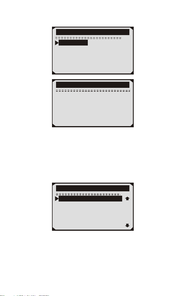
1/3
Live Daten
Datenanzeige
Datenwiedergabe
Datenaufzeichnung
Live Daten
L e s e P I D . . . 0 6
- B i t t e w a r t e n -
4) Um den vollständigen Datensatz anzuzeigen, verwenden Sie die
AUFWÄRTS / ABWÄRTS-Taste, um im Menü Daten anzeigen die
Option Vollständiger Datensatz auszuwählen, und drücken Sie die
Taste EINGABE.
5) Zeigen Sie Live-PIDs auf dem Bildschirm an. Verwenden Sie die
AUFWÄRTS / ABWÄRTS-Taste für weitere PIDs, wenn auf dem
Bildschirm ein AUF- oder AB-Pfeil erscheint.
* Die Zahl "x" rechts vom Bildschirm zeigt die Reihenfolge des
markierten Elements an.
* Wenn Sie den vollständigen Namen der hervorgehobenen PID
anzeigen möchten, drücken Sie die Taste Hilfe.
1/84
Live Daten
DTC_CNT 0
FUEL SYS2 OL
LOAD_PCT(%) 0.0
ECT( F) 80
SHRTFT1(%) 0.0
FUELSYS1 OL
。
54
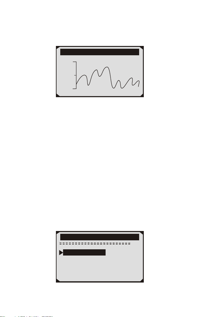
Wenn das Symbol angezeigt wird, wenn eine PID markiert ist,
bedeutet dies, dass Grafikinformationen verfügbar sind. Drücken
Sie ENTER, um das Diagramm anzuzeigen.
RPM(/min) 975
1725
925
6) Drücken Sie die ESC-Taste, um zum vorherigen Menü
zurückzukehren.
Sie dürfen maximal 18 PIDs aufnehmen, wenn die ausgewählten
PIDs 18 überschreiten, a "Die ausgewählte Datenliste ist voll!"
Nachricht wird auf dem Bildschirm angezeigt.
4.5.2 Daten aufzeichnen
Die Funktion "Daten aufzeichnen" ermöglicht das Aufzeichnen der
Parameteridentifikationsdaten (FID) der Fahrzeugmodule, um
intermittierende Fahrzeugprobleme zu diagnostizieren. Eine
Aufzeichnung enthält 5 Bilder von Live-Daten vor dem
Trigger-Ereignis und mehrere Frames nach dem Trigger-Ereignis.
Es gibt zwei Triggermodi, die zum Aufzeichnen von Daten
verwendet werden:
A. Manueller Trigger - ermöglicht dem Benutzer, die ENTER-Taste
zu drücken, um die Aufnahme zu starten.
B. DTC Trigger - zeichnet automatisch PID-Daten auf, wenn ein
Fehler, der zum Setzen eines DTC führt, vom Fahrzeug erkannt wird.
ACHTUNG: Versuchen Sie NICHT, den Scanner gleichzeitig zu
fahren und zu bedienen! Lassen Sie den Scanner während der Fahrt
immer von einer anderen Person bedienen.
2/3
Live Daten
Datenanzeige
Datenwiedergabe
Datenauzeichnung
55
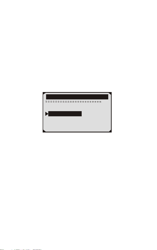
Der Scantool zeichnet PID-Daten auf, bis der Benutzer die
ESC-Taste drückt, der ausgewählte Speicherplatz voll ist oder
die Aufnahme beendet ist. Eine Aufforderung zur Wiedergabe von
Daten wird auf dem Bildschirm angezeigt.
4.5.3 Wiedergabe Daten
Die Wiedergabedaten-Funktion ermöglicht die Anzeige zuvor
gespeicherter PID-Daten.
1) Um aufgezeichnete Daten wiederzugeben, verwenden Sie die
AUFWÄRTS / ABWÄRTS-Tasten, um das Menü "Daten aus
Live-Daten wiedergeben" zu wählen und drücken Sie die
RNTER-Taste.
3/3
Live Daten
Datenanzeige
Datenauzeichnung
Datenwiedergabe
Sie können auch aufgenommene Daten sofort nach der Aufnahme
wiedergeben.
2) Wählen Sie mit den Tasten AUFWÄRTS / ABWÄRTS den
Speicherplatz, der mit einem Sternchen (*) gekennzeichnet ist.
Wenn an dem ausgewählten Ort keine Aufzeichnung stattfindet,
wird eine Meldung "Nicht unterstützt oder Keine Daten gespeichert"
auf dem Bildschirm angezeigt.
Für Daten, die im temporären Cache gespeichert sind, müssen Sie
nicht den Speicherort auswählen.
3) Verwenden Sie die AUFWÄRTS / ABWÄRTS-Taste, um
aufgezeichnete PIDs für jeden Frame anzuzeigen.
Verwenden Sie die EINGABETASTE, um Seiten oder Zeilen zu
konvertieren.
56
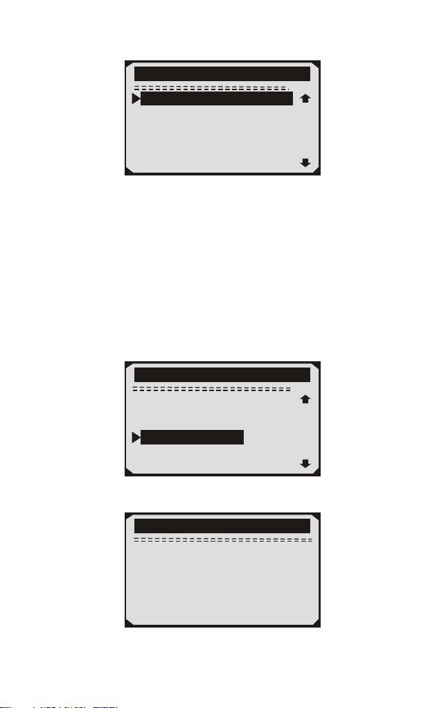
1/312
Datenwiedergabe
DTC_CNT 2
FUEL SYS2 CL
LOAD_PCT(%) 0.0
SHRTFT1(%) 48.4
DTC_CNT 2
FUEL SYS1 CL
Die Zahl "x / x" in der oberen rechten Ecke des Bildschirms zeigt die
Gesamtzahl der aufgezeichneten Frames und die Sequenz des
angezeigten Frames an.
Negative Frames zeigen Daten an, die vor dem Triggerereignis
aufgezeichnet wurden, und positive Frames zeigen Daten an, die
nach dem Triggerereignis aufgezeichnet wurden.
4.6 Aussicht Gefrorener Rahmen Daten
1) Um Gefrorener Rahmen Daten anzuzeigen, verwenden Sie die
AUFWÄRTS / ABWÄRTS-Taste, um Freeze Frame anzeigen im
Diagnosemenü auszuwählen, und drücken Sie die ENTER-Taste.
4/11
Diagnosemenü
Lese Codes
Losche Codes
Live Daten
I/M Staus
Lamdasonde Prüfung
Anzeig Freeze Frame
2) Warten Sie ein paar Sekunden, während das Diagnose-Tool den
PID MAP validiert.
Anzeig Freeze Frame
L e s e P I D . . . 0 6
- B i t t e w a r t e n -
57

3) Wenn in Formation abgerufen deckt mehr als offenen Bildschirm,
dann erscheint ein Pfeil nach unten. Verwenden Sie ggf. die
ABWÄRTS-Taste, bis alle Daten angezeigt wurden.
Wenn keine Gefrorener Rahmen Daten verfügbar sind, wird die
Meldung "Keine Gefrorener Rahmen Daten gespeichert!" erscheint
auf dem Display.
4) Wenn Sie den vollständigen Namen einer PID anzeigen möchten,
verwenden Sie die AUFWÄRTS / ABWÄRTS-Taste, um die PID
auszuwählen, und drücken Sie die Taste HELP.
1/8
Anzeig Freeze Frame
DTCCFRZF B0090
LOAD_PCT(%) 0.0
ETC( F) 417
MAP(inH9) 76.2
RPM(/min) 12210
VSS(mph) 157
。
5) Warten Sie einige Sekunden, bis Sie eine beliebige Taste drücken,
um zum vorherigen Bildschirm zurückzukehren.
4.7 Abrufen I/M Bereitschaft Status
Die I/M Readiness-Funktion wird verwendet, um den Betrieb des
Emissionssystems an OBD2-konformen Fahrzeugen zu überprüfen.
Es ist eine ausgezeichnete Funktion zu verwenden, bevor ein
Fahrzeug in Übereinstimmung mit einem staatlichen
Emissionsprogramm inspiziert wird.
A.DTCs Cleared - zeigt den Status der Monitore an, seit die DTCs
gelöscht wurden.
B.Dieser Laufwerkzyklus - zeigt den Status der Monitore seit dem
Beginn des aktuellen Laufwerkzyklus an.
Die I/M Readiness-Funktion wird verwendet, um den Betrieb des
Emissionssystems an OBD2-konformen Fahrzeugen zu überprüfen.
Es ist eine ausgezeichnete Funktion zu verwenden, bevor ein Fahrzeug
in Übereinstimmung mit einem staatlichen Emissionsprogramm
inspiziert wird.
58
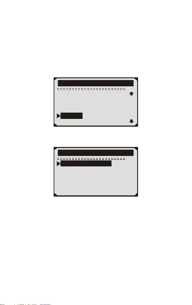
"OK" - Zeigt an, dass ein bestimmter Monitor, der geprüft wird,
seinen Diagnosetest abgeschlossen hat.
"INC" - Zeigt an, dass ein bestimmter Monitor, der geprüft wird,
seine Diagnoseprüfung nicht abgeschlossen hat.
"N/A" - Der Monitor wird von diesem Fahrzeug nicht unterstützt.
1) Verwenden Sie die AUFWÄRTS / ABWÄRTS-Tasten, um I / M
Readiness vom Diagnosemenü auszuwählen, und drücken Sie die
ENTER-Taste.
5/11
Diagnosemenü
Lese Codes
Losche Codes
Live Daten
Anzeig Freeze Frame
Lamdasonde Prüfung
I/M Staus
2) Wenn das Fahrzeug beide Arten von Tests unterstützt, werden
beide Typen zur Auswahl auf dem Bildschirm angezeigt.
1/2
I/M Status
Seit L schung DTCSö
Dieser fahrt
3) Benutzen Sie die AUFWÄRTS / ABWÄRTS-Taste, um den Status
der MIL-Leuchte ("ON" oder "OFF") und der folgenden Monitore
anzuzeigen:
Fehlzündung Monitor - Fehlzündung Monitor
Kraftstoffsystem Mon - Kraftstoffsystem Monitor
Komp. Komponente - Comprehensive Components Monitor
AGR - AGR-Systemmonitor
Oxygen Sens Monitor Mon - 02 Sensoren
Katalysator Mon - Katalysator Monitor
EVAP System Mon - Verdunstungssystem Monitor
Oxygen Sen htr - Sauerstoffsensor Heizungsüberwachung
•
•
•
•
•
•
•
•
59
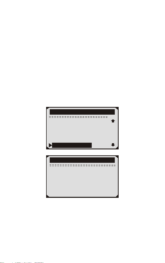
• Sec Air System - Sekundärluftüberwachung
• Htd Catalyst - Heizkatalysatormonitor
• A / C Refrig Mon – Systemmonitor
4) Drücken Sie die ESC-Taste, um zum Diagnosemenü
zurückzukehren.
4.8 Sauerstoff (O2) Sensor Monitor Prüfung
Die O2-Monitor-Testfunktion ermöglicht die Abfrage und Anzeige
von O2-Sensormonitor-Testergebnissen für die zuletzt
durchgeführten Tests vom Bordcomputer des Fahrzeugs.
1) Verwenden Sie die AUFWÄRTS / ABWÄRTS-Taste, um den
O2-Monitor-Test im Diagnosemenü auszuwählen, und drücken
Sie die ENTER-Taste.
6/11
Diagnosemenü
Lese Codes
Losche Codes
Live Daten
Anzeig Freeze Frame
I/M Staus
Lamdasonde Prüfung
Lamdasonde Prüfung
L e s e P I D . . . 0 6
- B i t t e w a r t e n -
2)Warten Sie ein paar Sekunden, während das Diagnose-Tool den
PID MAP validiert.
3)Verwenden Sie die AUFWÄRTS / ABWÄRTS-Taste, um den
O2-Sensor aus dem O2-Monitor-Testmenü auszuwählen, und
drücken Sie die ENTER-Taste.
60
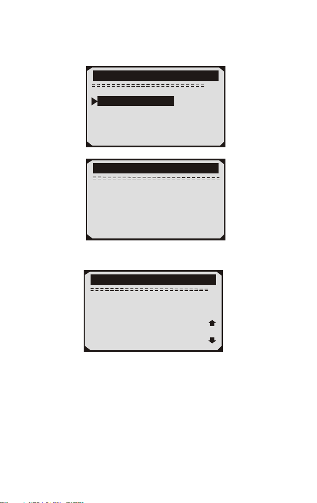
Wenn das Fahrzeug den Modus nicht unterstützt, wird eine
Hinweismeldung auf dem Bildschirm angezeigt.
2/2
Lamdasonde Prüfung
02 Mon. B1S1
02 Mon. B1S2
O2 Mon. B1S1
Der gewählte Modus wirdnicht
unterstützt
Jeder Taste fortsetze
4) Zeigen Sie die Testergebnisse des ausgewählten O2-Sensors an.
O2 Mon. B1S2
Sensor fett zu
mager(V)
MEAS : 0.0000(V)
MIN : 0.0000(V)
MAX : 0.0000(V)
STS : Pass
1/3
5) Verwenden Sie die AUFWÄRTS- / ABWÄRTS-Taste, um weitere
Bildschirme mit Daten anzuzeigen, wenn ein AUFWÄRTS - oder
ABWÄRTS -Symbol angezeigt wird.
6) Drücken Sie die ESC-Taste, um zu den vorherigen Menüs
zurückzukehren.
61
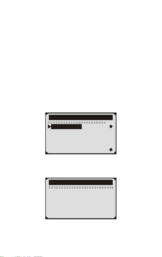
4.9 Am-Bordmonitor Prüfung
Der On-Board-Monitor-Test ist nach einer Wartung nützlich,
nachdem der Speicher eines Fahrzeugsteuermoduls gelöscht wurde.
Der On-Board-Monitor-Test für nicht mit CAN ausgerüstete
Fahrzeuge liefert Testergebnisse für emissionsbezogene
Antriebsstrangkomponenten und Systeme, die nicht ständig
überwacht werden, und zeigt diese an. Der On-Board-Monitor-Test
für mit CAN ausgerüstete Fahrzeuge liefert Testergebnisse für
emissionsbezogene Antriebsstrangkomponenten und -systeme, die
ständig überwacht werden und nicht überwacht werden, und zeigt
diese an. Test- und Komponenten-IDs werden vom
Fahrzeughersteller ermittelt.
1) Verwenden Sie die AUFWÄRTS/ABWÄRTS -Tasten, um
On-Board Mon auszuwählen. Testen Sie im Diagnosemenü und
drücken Sie die ENTER-Taste.
7/11
Diagnosemenü
Monitor prüfung
Komponenten prüfung
Fahrzug Info
Modul verfügbar
MaßEinheit
Monitor prüfung
L e s e P I D . . . 0 6
- B i t t e w a r t e n -
2) Warten Sie ein paar Sekunden, während das Diagnose-Tool den
PID MAP validiert.
62
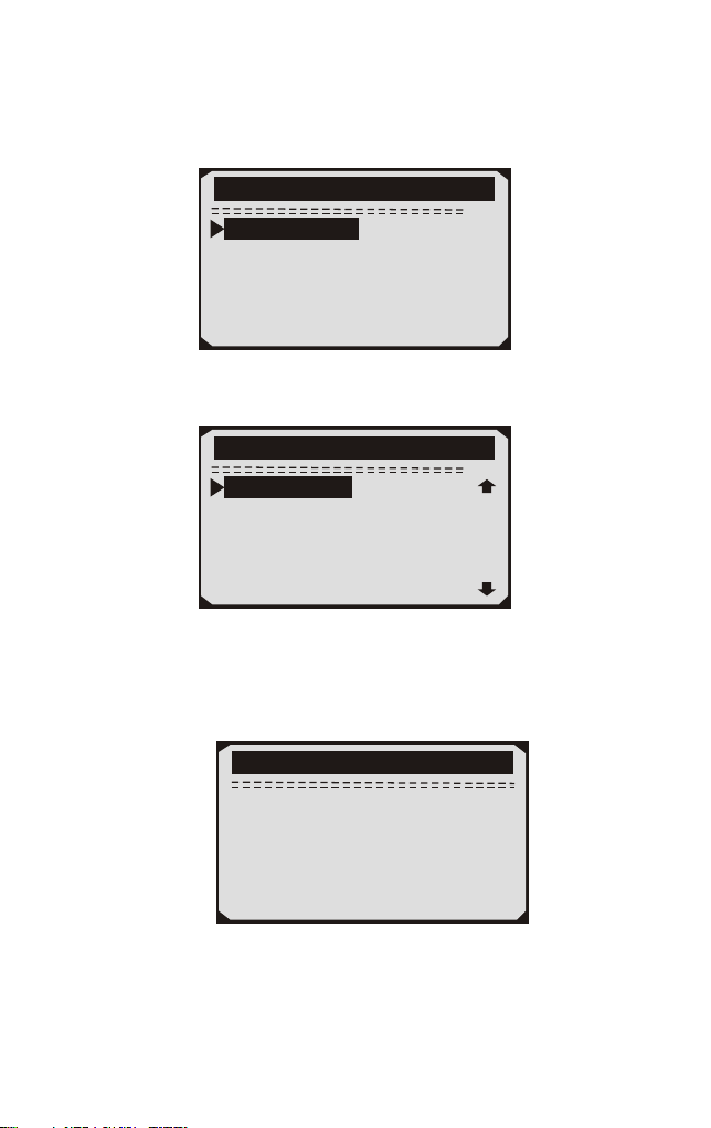
3) Von On-Board Mon.Testen Sie das Menü, verwenden Sie die
AUFWÄRTS/ABWÄRTS -Taste, um einen Test zur Ansicht
auszuwählen, und drücken Sie die ENTER-Taste.
1/3
Monitor prüfung
Test S01 Daten
Test S05 Daten
Test S09 Daten
Wenn das zu testende Fahrzeug den Modus nicht unterstützt, wird
eine Hinweismeldung auf dem Bildschirm angezeigt.
1/4
Monitor prüfung
Catalyst Mon.B1
Heizung Mon.B1S1
Beheizter Katalysator B1
Heizung Mon.B1S2
4) Verwenden Sie die AUFWÄRTS/ABWÄRTS-Tasten, um den
gewünschten Monitor von On-Board Mon auszuwählen. Testen Sie
das Menü und drücken Sie die ENTER-Taste.
5) Zeigen Sie Testdaten auf dem Bildschirm an.
02 Heizung Mon.B1-S1
SOD TEST
MEAS : 10.180(V)
MIN : 10.500(V)
MAX : 13.800(V)
STS : Fall
63

Für mit CAN ausgerüstete Fahrzeuge können folgende
Testergebnisse angezeigt werden:
Catalyst Mon.B1
Mager bis reich
sensor(V)
MEAS : 6. 0540(V)
MIN : 3.4071(V)
MAX : 4.1642(V)
STS : Fall
6) Drücken Sie die ESC-Taste, um zu den vorherigen Menüs zurück
zu kehren.
4.10 Komponenten Prüfung
Die Komponententestfunktion ermöglicht das Einleiten eines
Lecktests für das EVAP-System des Fahrzeugs. Das Diagnose-Tool
selbst führt den Lecktest nicht durch, sondern befiehlt dem
Bordcomputer des Fahrzeugs, den Test zu starten. Verschiedene
Fahrzeughersteller haben möglicherweise unterschiedliche Kriterien
und Methoden, um den Test nach dem Start zu stoppen. Bevor Sie den
Komponententest starten, lesen Sie im Wartungshandbuch des
Fahrzeugs nach, wie Sie den Test stoppen können.
1) Verwenden Sie die AUFWÄRTS/ABWÄRTS-tasten um
Komponenten test im Diagnosemenü auszuwählen und drücken Sie
die ENTER-Taste.
8/11
Diagnosemenü
Monitor pr
Fahrzug Info
Modul verfügbar
MaßEinheit
üfung
Komponenten prüfung
64

2) Wählen Sie im Komponententest mit der Taste
AUFWÄRTS/ABWÄRTS den Test aus, der gestartet werden soll.
1/1
Komponenten prüfung
Evap Leak Pr fungü
3) Wenn der Test vom Fahrzeug initiiert wurde, wird eine
Bestätigungs meldung auf dem Bildschirm angezeigt.
Einige Fahrzeuge erlauben keine Scan-Tools zur Steuerung von
Fahrzeugsystemen oder -komponenten. Wenn das zu testende
Fahrzeug den EVAP-Lecktest nicht unterstützt, wird eine
Hinweismeldung auf dem Bildschirm angezeigt.
Evap Leak Pr fungü
Der gewählte Modus
wirdnicht unterstützt
Jeder Taste fortsetze
4)Warten Sie einige Sekunden oder drücken Sie eine beliebige Taste,
um zum Diagnosemenü zurückzukehren.
4.11 Ansicht Fahrzeuginformationen
Die Funktion Fahrzeug info ermöglicht den Abruf von Fahrzeugi
dentifikations nummer (VIN), Kalibrierungs-ID (s), Kalibrierungs
nummer (CVN) und In-Use-Leistung sverfolgung bei Fahrzeugen
ab 2000, die Modus 9 unterstützen.
65
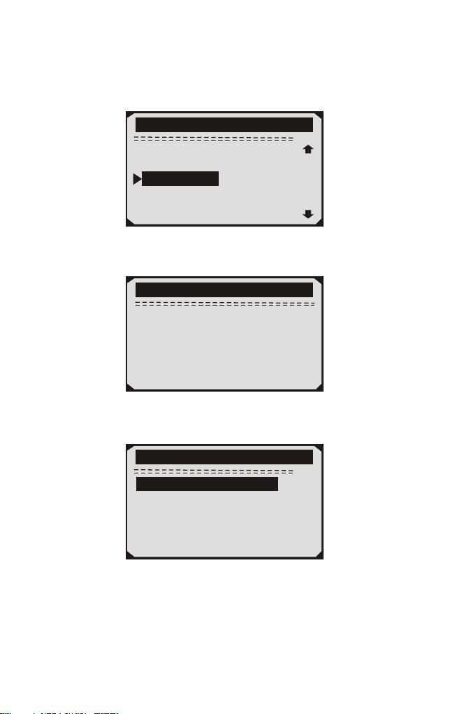
1) Verwenden Sie die AUF / AB-tasten, um Fahrzeuginformationen
aus dem Diagnosemenü auszuwählen und drücken Sie die
ENTER-Taste.
9/11
Diagnosemenü
Monitor pr
Komponenten prüfung
Modul verfügbar
MaßEinheit
üfung
Fahrzug Info
2) Warten Sie ein paar Sekunden, während das Diagnose-Tool die
Fahrzeug informationen liest.
Fahrzug Info
L e s e P I D . . . 0 6
- B i t t e w a r t e n -
3) Anzeigen der abgerufenen Fahrzeug informationen auf dem
Bildschirm.
9/11
Fahrzuug Info
VIN:WBAVC57548NK78049
CID1:7602216
CID2:7625429
CIN1:F72C8FB0
CIN2:A4649AC0
4) Drücken Sie die ESC-Taste, um zum vorherigen Menü
zurückzukehren
66

4.12 LED Deutung
1) GRÜNE LED - Zeigt an, dass die Motorsysteme "OK" sind und
normal funktionieren (die Anzahl der vom Fahrzeug unterstützten
Monitore, die ihre Selbstdiagnosetests ausgeführt haben und
ausführen, liegt innerhalb des erlaubten Grenzwerts. MEL ist
ausgeschaltet). Es gibt keine gespeicherten und ausstehenden DTCs.
Das Fahrzeug ist bereit für einen Emissionstest und es besteht eine
gute Möglichkeit, dass es zertifiziert werden kann.
2) GELBE LED ~ Bei ausgeschaltetem MIL können drei Zustände
auftreten, die die gelbe LED aufleuchten lassen.
A.Wenn ein "gespeicherter" Diagnose-Fehlercode die gelbe LED
aufleuchtet, ist es möglich, dass das Fahrzeug auf Emissionen
getestet und zertifiziert werden kann.
B.Wenn ein "Pending" Diagnose-Fehlercode die gelbe LED
aufleuchtet, ist es dennoch möglich, dass das Fahrzeug auf
Emissionen getestet und zertifiziert werden kann.
C.Wenn die Beleuchtung der gelben LED durch Monitore
verursacht wird, die ihre Diagnoseprüfung nicht abgeschlossen
haben, hängt die Frage, ob das Fahrzeug für einen Emissionstest
bereit ist, von den Emissionsvorschriften und Gesetzen Ihrer Region
ab. HINWEIS: Ermitteln Sie anhand des Code-Abrufverfahrens den
Status jedes Monitors und leiten Sie diese Informationen an einen
Fachmann weiter, um festzustellen, ob Ihr Fahrzeug für einen
Emissionstest bereit ist (basierend auf Ihren Testergebnissen).
3) ROTE LED - Zeigt an, dass ein Problem mit einem oder mehreren
Systemen des Fahrzeugs vorliegt. Ein Fahrzeug mit einer roten LED
ist definitiv nicht für einen Emissionstest bereit. Die rote LED ist
auch Fahrzeug Instrumententafel leuchtet konstant. Das Problem,
dass die rote LED leuchtet, muss repariert werden, bevor ein
Emissionstest durchgeführt werden kann. Es wird auch empfohlen,
das Fahrzeug vor dem weiteren Führen des Fahrzeugs zu
inspizieren / reparieren.
A.Reparieren Sie das Fahrzeug selbst. Wenn Sie die Reparaturen
selbst durchführen möchten, lesen Sie zunächst das Handbuch für die
Fahrzeugwartung und befolgen Sie alle Verfahren und Empfehlungen.
B.Nehmen Sie das Fahrzeug zu einem Fachmann, um es zu warten.
Das Problem, dass die rote LED leuchtet, muss repariert werden,
bevor das Fahrzeug bereit für einen Emissionstest ist.
67

5. Drucken Diagnose bericht
Die Funktion "Daten drucken" ermöglicht das Hochladen der
aufgezeichneten Daten per Scan-Tool an Windows-PCs zum
Ausdrucken (Windows-PC muss mit Druckern verbunden sein).
Sie können die Daten / Berichte vor dem Drucken auf dem
Computer anpassen.
Um die aufgezeichneten Daten hochzuladen, benötigen Sie
folgende Tools:
1.Scan-Werkzeug
2.A Windows PC or laptop with USB ports. (Support only official
version Windows XP-10, 32/64 bits OS)
3.Ein USB-Kabel
Schritte:
1) Laden Sie die Anwendungen von der offiziellen Website herunter und
installieren Sie sie: auf Windows-Computern.
* Bitte deaktivieren Sie die Antivirensoftware, wenn eine Warnmeldung
angezeigt wird.Andernfalls wird der Treiber möglicherweise nicht
ordnungsgemäß installiert
* Bitte ignorieren Sie den Installationsfehler der Microsoft
Modem-Treiber, falls Sie dies tunVerwenden Sie kein Windows
XP-System.
2) Schließen Sie den Scanner mit dem mitgelieferten USB-Kabel an
den Computer an.
3) Führen Sie die UPLINK.exe auf Ihrem PC aus.
4) Wählen Sie mit der AUF / AB-Taste die Option Daten drucken aus
dem Hauptmenü Menü im Scan-Tool und drücken Sie die OK-Taste.
5) Wählen Sie mit der AUF / AB-Taste die gewünschte Option aus
Drucken aus dem Menü Daten drucken.Um alle abgerufenen Daten zu
drucken, verwenden Sie die UP / DOWN-Tasten, um auszuwählen
Alle Daten aus dem Menü Druckdaten drucken.
6) Drücken Sie die OK-Taste, um Daten auf den Computer hochzuladen.
7) Im UPLINK.exe-Toolkit können Sie bearbeiten, löschen, kopieren
und Drucken Sie die Daten im Textfeld, indem Sie die Symbole oben
auswählen rechts vom Fenster
HINWEIS: Daten, die in einer Sprache gespeichert sind, die sich von
den aktuellen Systemeinstellungen des Scantools unterscheidet, können
nicht gedruckt werden. Bitte passen Sie die Spracheinstellungen vor dem
Drucken an. Eine Erinnerung würde unter solchen Umständen auftauchen.
www.nexpeaktech.com
68
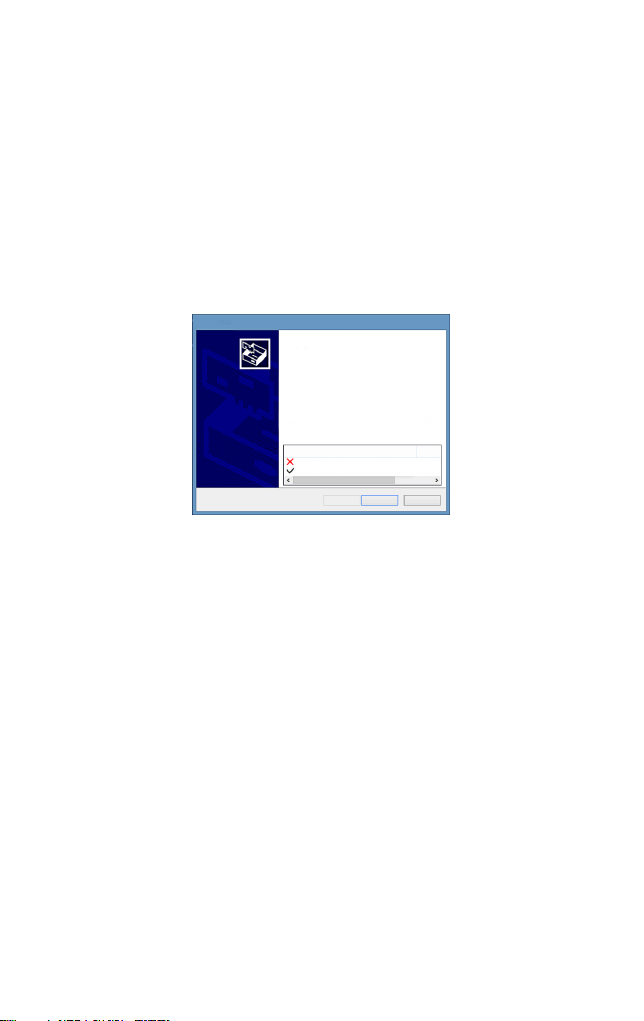
6. Aktualisieren Das Scan Werkzeug
Mit dieser Funktion können Sie die Software des Diagnose-Tools und
die DTC-Bibliothek über einen Windows-Computer aktualisieren.
Ihr Scan-Tool zu aktualisieren, benötigen Sie die folgenden Elemente.
1.Scan-Werkzeug
2.Ein PC oder Laptop mit USB-Anschlüssen. (Support nur offizielle
Version Windows XP-10, 32/64 Bits OS)
3.USB-Kabel
Schritte:
Laden Sie die Anwendungen von unserer Website herunter
1)
und installieren Sie sie: www.nexpeaktech.com
Device Driver Installation Wizard
Completing the Device Driver
Installation Wizard
Some drivers were successfully installed on this computer.Some
could not be installed.See the Status column for more details.
if a device came with your software,you can now connect it to this
computer.
For devices where no driver was installed.contact your device
vendor.
Drvier Name
Status
Microsoft Modem (06/21/2006 6.1.7601.17514) Install fai
STMicroelectronics (usbser) Ports (04/25/2010... Ready to
< Back
Finish
Cancel
Bitte ignorieren Sie den Installationsfehler der Microsoft Modem-Treiber, wenn Sie kein Windows XP-System verwenden.
69
2) Führen Sie uplink.exe auf Ihrem Computer aus (Mac OS ist nicht
kompatibel)
3) Halten Sie eine beliebige Taste gedrückt, bis das USB-Kabel mit
dem Computer verbunden ist, und lassen Sie sie los, wenn das
Diagnose-Tool die Meldung "Aktualisierungsmodus" anzeigt.
4) Kehren Sie zur Uplink-Software zurück, klicken Sie auf "Update
prüfen", laden Sie die Upgrade-Datei aus dem Internet herunter und
aktualisieren Sie sie automatisch auf das Scan-Tool.
5) Warten Sie einige Minuten, bis das Update erfolgreich ist.
6) Bitte trennen Sie während des Update-Vorgangs die
USB-Verbindung nicht.
7) Starten Sie das Scan-Tool neu, um das gesamte Update
abzuschließen.
HINWEIS: Wenn Sie eine falsche Auswahl getroffen haben und der
Diagnose-Tester nicht ordnungsgemäß funktioniert, müssen Sie
möglicherweise die Programme aktualisieren. Um den LINKEN
Scroll-Knopf zu halten und den Scanner einzuschalten,Sie werden
zwangsweise in den Aktualisierungsmodus wechseln. Folgen Sie
dann dem Aktualisierung-Vorgang, um das Programm zu aktualisieren.

7. Blinddarm
7.1 Anhang 1-PID-Liste
PID Abbreviation
Full Name
DTC_CNT
DTCFRZF
FUELSYS1
FUELSYS2
LOAD_PCT(%)
ECT( F)
ETC( C)
SHRTFT1(%)
SHRTFT3(%)
LONGFT1(%)
LONGFT3(%)
SHRTFT2(%)
SHRTFT4(%)
LONGFT2(%)
LONGFT4(%)
FRP(kPa)
FRP(psi)
MAP(kPa)
MAP(inHg)
RPM(/min)
VSS(km/h)
VSS(mph)
SPARKADV(\x82)
IAT( F)
IAT( C)
MAF(g/s)
MAF(1b/min)
TP(%)
。
。
。
。
DTC Stored Number
DTC
Fuel System 1 Status
Fuel System 2 Status
Calculated Load Value
Engine Coolant Temperature
Engine Coolant Temperature
Short Term Fuel Trim-Bank1
Short Term Fuel Trim-Bank3
Long Term Fuel Trim-Bank1
Long Term Fuel Trim-Bank3
Short Term Fuel Trim-Bank2
Short Term Fuel Trim -Bank4
Long Term Fuel Trim-Bank2
Long Term Fuel Trim-Bank4
Fuel Rail Pressure(gauge)
Fuel Rail Pressure(gauge)
Intake Manifold Absolut Pressure
Intake Manifold Absolut Pressure
Engine RPM
Vehicle Speed Sensor
Vehicle Speed Sensor
Ignition Timing Advance for #1
Intake Air Temperature
Intake Air Temperature
Mass Air Flow Sensor
Mass Air Flow Sensor
Absolut Throttle Position
70

PID Abbreviation
Full Name
AIR-STAT
O2SLOC
O2B1S1(V)
SHRTFTB1S1(%)
O2B1S2(V)
SHRTFTB1S2(%)
O2B1S3(V)
SHRTFTB1S3(%)
O2B1S4(V)
SHRTFTB1S4(%)
O2B2S1(V)
SHRTFTB2S1(%)
O2B2S2(V)
SHRTFTB21S2(%)
O2B2S3(V)
SHRTFTB2S3 (%)
O2B2S4(V)
SHRTFTB21S4(%)
O2B1S1(V)
SHRTFTB1S1(%)
O2B1S2(V)
SHRTFTB1S2(%)
O2B2S1(V)
SHRTFTB2S1(%)
O2B2S2(V)
SHRTFTB2S2(%)
O2B3S1(V)
SHRTFTB3S1(%)
O2B3S2(V)
SHRTFTB3S2(%)
O2B4S1(V)
Commanded Secondary Air Status
Location of O2 Sensors
O2 Sensor Output Voltage(B1S1)
Short Term Fuel Trim(B1S1)
O2 Sensor Output Voltage(B1S2)
Short Term Fuel Trim(B1S2)
O2 Sensor Output Voltage(B1S3)
Short Term Fuel Trim(B1S3)
O2 Sensor Output Voltage(B1S4)
Short Term Fuel Trim(B1S4)
O2 Sensor Output Voltage(B2S2)
Short Term Fuel Trim(B2S2)
O2 Sensor Output Valtage(B2S3)
Short Term Fuel Trim(B2S3)
O2 Sensor Output Voltage(B2S4)
Short Term Fuel Trim(B2S4)
O2 Sensor Output Voltage(B2S1)
Short Term Fuel Trim(B2S1)
O2 Sensor Output Voltage(B1S2)
Short Term Fuel Trim(B1S2)
O2 Sensor Output Voltage(B2S1)
Short Term Fuel Trim(B2S1)
O2 Sensor Output Voltage(B2S2)
Short Term Fuel Trim(B2S2)
O2 Sensor Output Voltage(B3S1)
Short Term Fuel Frim(B3S1)
O2 Sensor Output Voltage(B3S2)
Short Term Fuel Trim(B3S2)
O2 Sensor Output Voltage(B4S1)
O2 Sensor Output Voltage(B2S1)
Short Term Fuel Trim(B2S1)
71

PID Abbreviation
Full Name
SHRTFTB4S1(%)
O2B4S2(V)
SHRTFRB4S2(%)
OBDSUP
O2SLOC
RUNTM(sec)
MIL_DIST(km)
FRP(kpa)
FRP(PSI)
FRP(kpa)
FRP(PSI)
EQ_RATB1S1
O2B1S2(V)
EQ_RARB1S2
O2B1S2(V)
EQ_RATB1S3
O2B1S3(V)
EQ_RATB1S4
O2B1S4(V)
EQ_RATB2S1
O2B2S1(V)
EQ_RATB2S2
O2B2S2(V)
EQ_RATB2S3
O2B2S3(V)
EQ_RATB2S4
O2B2S4(V)
EQ_RATB1S1
O2B1S1(V)
EQ_RATB1S2
O2B1S2(V)
MIL_DIST(milc)
Short Term Fuel Trim(B4S1)
O2 Sensor Output Voltage(B4S2)
Short Term Fuel Trim(B4S2)
OBD Require To Whic Vehicle Designed
Location Of O2 Sensors
Time Since Engine Start
Distance Travelled While MIL Activated
Distance Travelled While MIL Activated
FuelRail Pres. Relative To Manifold Vacuum
FuelRail Pres. Relative To Manifold Vacuum
Fuel Rail Pressure
Fuel Rail Pressure
Equivalence Ratio(wide range O2S)(B1S1)
O2 Sensor Voltage(wide range O2S)(B1S1)
Equivalence Ratio(wide range O2S)(B1S2)
O2 Sensor Voltage(wide range O2S)(B1S2)
Equivalence Ratio(wide range O2S)(B1S3)
O2 Sensor Voltage(wide range O2S)(B1S3)
Equivalence Ratio(wide range O2S)(B1S4)
O2 Sensor Voltage(wide range O2S)(B1S4)
Equivalence Ratio(wide range O2S)(B2S1)
O2 Sensor Voltage(wide range O2S)(B2S1)
Equivalence Ratio(wide range O2S)(B2S2)
O2 Sensor Voltage(wide range O2S)(B2S2)
Equivalence Ratio(wide range O2S)(B2S3)
O2 Sensor Voltage(wide range O2S)(B2S3)
Equivalence Ratio(wide range O2S)(B2S4)
O2 Sensor Voltage(wide range O2S)(B2S4)
Equivalence Ratio(wide range O2S)(B2S1)
O2 Sensor Voltage(wide range O2S)(B2S1)
Equivalence Ratio(wide range O2S)(B1S2)
O2 Sensor Voltage(wide range O2S)(B1S2)
72

PID Abbreviation
Full Name
EQ_ RATB2S1
O2B2S1(V)
EQ_RATB2S2
O2B2S2(V)
EQ_RATB3S1
O2B3S1(V)
EQ_RATB3S2
O2B3S2(V)
EQ-RATB4S1
O2B4S1(V)
EQ_RATB4S2
O2B4S2(V)
EGR_PRC(%)
EGR_ERR(%)
EVAP_PCT(%)
FLI(%)
WARM_UPS
LCR_DIST(km)
CLR_DIST(mile)
EVAP_VP(Pa)
EVAP_VP(inH2O)
BARO(kPa)
BARO(inHg)
EQ_ART11
O2S11(mA)
EQ_RAT13
O2S13(mA)
EQ_RAT14
O2S14(mA)
EQ_RAT21
EQ_RAT12
O2S12(mA)
Equivalence Ratio(wide range O2S)(B2S1)
O2 Sensor Voltage(wide range O2S)(B2S1)
Equivalence Ratio(wide range O2S)(B2S2)
O2 Sensor Voltage(wide range O2S)(B2S2)
Equivalence Ratio(wide range O2S)(B3S1)
O2 Sensor Voltage(wide range O2S)(B3S1)
Equivalence Ratio(wide range O2S)(B3S2)
O2 Sensor Voltage(wide range O2S)(B3S2)
Equivalence Ratio(wide range O2S)(B4S1)
O2 Sensor Voltage(wide range O2S)(B4S1)
Equivalence Ratio(wide range O2S)(B4S2)
O2 Sensor Voltage(wide range O2S)(B4S2)
Commanded EGR
EGR Error
Commanded Evaporative Purge
Fuel Level Input
Number of Warm-ips Since DTC Cleared
Distance Since DTC Cleared
Distance Since DTC Cleared
Evap System Vapor Pressure
Evap System Vpor Pressure
Barometric Pressure
Barometric Pressure
Equivalence Ratio(wide range O2S)(B1S1)
O2 Sensor Current(wide range O2S)(B1S1)
Equivalence Ratio(wide range O2S)(B1S2)
O2 Sensor Current(wide range O2S)(B1S2)
Equivalence Ratio(wide range O2S)(B1S3)
O2 Sensor Current(wide range O2S)(B1S3)
Equivalence Ratio(wide range O2S)(B1S4)
O2 Sensor Current(wide range O2S)(B1S4)
Equivalence Ratio(wide range O2S)(B2S1)
73

PID Abbreviation
Full Name
O2S21(mA)
EQ_RAT22
O2S22(mA)
EQ_RAT23
O2S23(mA)
EQ_RAT24
O2S24(mA)
EQ_RAT11
O2S11(mA)
EQ_RAT12
O2S12(mA)
EQ_RAT21
O2S21(mA)
EQ_RAT22
O2S22(mA)
EQ_RAT31
O2S31(mA)
EQ_RAT32
O2S321(mA)
EQ_RAT41
O2S41(mA)
EQ_RAT42
O2S42(mA)
CATEMP11( F)
CATEMP11( C)
CATEMP21( F)
CATEMP21( C)
CATEMP12( F)
CATEMP12( C)
CATEMP22( F)
CATEMP22( C)
VPWR(V)
。
。
。
。
。
。
。
。
O2 Sensor Current(wide range O2S)(B2S1)
Equivalence Ratio(wide range O2S)(B2S2)
O2 Sensor Current(wide range O2S)(B2S2)
Equivalence Ratio(wide range O2S)(B2S3)
O2 Sensor Current(wide range O2S)(B2S3)
Equivalence Ratio(wide range O2S)(B2S4)
O2 Sensor Current(wide range O2S)(B2S4)
Equivalence Ratio(wide range O2S)(B2S1)
O2 Sensor Current(wide range O2S)(B2S1)
Equivalence Ratio(wide range O2S)(B1S2)
O2 Sensor Current(wide range O2S)(B1S2)
Equivalence Ratio(wide range O2S)(B2S1)
O2 Sensor Current(wide range O2S)(B2S1)
Equivalence Ratio(wide range O2S)(B2S2)
O2 Sensor Current(wide range O2S)(B2S2)
Equivalence Ratio(wide range O2S)(B3S1)
O2 Sensor Current(wide range O2S)(B3S1)
Equivalence Ratio(wide range O2S)(B3S2)
O2 Sensor Current(wide range O2S)(B3S2)
Equivalence Ratio(wide range O2S)(B4S1)
O2 Sensor Current(wide range O2S)(B4S1)
Equivalence Ratio(wide range O2S)(B4S2)
O2 Sensor Current(wide range O2S)(B4S2)
Catalyst Temperature Bank 1 Sensor1
Catalyst Temperature Bank 1 Sensor1
Catalyst Temperature Bank 2 Sensor1
Catalyst Temperature Bank 2 Sensor1
Catalyst Temperature Bank 1 Sensor2
Catalyst Temperature Bank 1 Sensor2
Catalyst Temperature Bank 2 Sensor2
Catalyst Temperature Bank 2 Sensor2
Control Module Voltage
74

PID Abbreviation
Full Name
LOAD_ABS(%)
EQ_RAT
TP_R(%)
AAT( F)
AAT( C)
TP_B(%)
TP_C(%)
APP_D(%)
APP_F(%)
APP_F(%)
TAC_PCT(%)
MIL_TIME
CLR_TIME
Absolute Load Value
Commanded Equivalence Ratio
Relative Throttle Position
Ambient Air Temperature
Ambient Air Temperature
Absolute Throttle Position B
Absolute Throttle Position C
Accelerator Pedal Position D
Accelerator Pedal Position E
Accelerator Pedal Position F
Commanded Throttle Actuator Control
Minute run by Engine While MIL activated
Time since Diagnostic Trouble Code Clear
7.2 Anhang 2 Liste der Daten zur Leistungs berwachung
nach Gebrauch
ü
Abbreviaiton Full Name Definitions
OBDCOND
IGNCNTR
CATCIMPI
OBD
Monitoring
Conditions
Encountered
Encountered
Counts
Ignition Counter
Catalyst
Monitor
Completion
Counts Bank 1
OBD Monitoring Conditions
Encountered Counts displays ESC
for the number of times that the
vehicel has been operated in the
specified OBD monitoring
conditions(general denominator).
Ignition Counter displays the
count of ESC number of times
that the engine has been started.
Catalyst Monitor completion
Counts Bank 1 displays ESC
number of times that all
conditions necessary to detect a
catalyst system bank 1
malfunction have been
encountered(numerator).
CATCONDI
Catalyst
Monitor
Conditions
Encountered
Const Bank
Catalyst Monitor Conditions
Encountered Counts Bank 1
displays ESC number of times
that the vehicle has been operated
in the specified catalyst
monitoring conditions
(denominator).
75

CATCOND2
O2SC0MP1
O2SC0ND1
O2SC0MP2
O2SC0ND2
EGRCOMP
EGRCOND
Catalyst
Monitor
Conditions
Encountered
Counts Bank 2
O2 Sensor
Monitor
Completion
Counts Bank 1
O2 Sensor Monitor
Conditions
Encountered
Counts Bank 1
O2 Sensor Monitor
Completion Counts
Bank2
O2 Sensor Montior
Conditions
Encountered
Counts Bank 2
EGR Monitor
Completion
Condition Counts
EGR Monitor
Conditions
Encountered
Counts
Catalyst Monitor Conditions
Encountered Counts Bank 2
displays ESC number of times
that the vehicle has been operated
in the specified catalyst
monitoring conditions
(denominator)
O2 Sensor Monitor Completion
Counts Bank 1displays ESC
number of time that all conditions
necessary to detect an oxygen
sensor bank 1malfunction have
been encountered(numerator).
O2 Sensor Monitor Completion
Encountered Counts Bank 1
displays ESC number of times
that the vehicle has been operated
in the specified oxygen sensor
monitoring gonditions
(denominator)
O2 Sensor Monitor Completion
Counts Bank 2 displays ESC
number of times that all conditions
necessary to detect an oxygen sensor
bank 2 malfunction have been
encountere(numerator).
O2 Sensor Monitor Completion
Encountered Counts Bank 2
displaysESC number of times that
the vehicle has been operated in
the specified oxygen sensor
monitoring conditions(denominator)
EGR Monitor Completion Condition
Counts displays ESC number of
timesthat all conditions necessary to
detect an EGR system malfunction
have been encountered (numerator).
EGR Monitor Completion
Encountered Counts displays
ESC number of times that the
vehicle has been operated in the
specified EGR system monioring
conditions(denominator).
76

AIRCOMP
AIRCOND
EVAPCOMP
EVAPCOND
AIR Monitor
Completion
Condition Counts
(Secondary Air)
AIR Monitor
Conditions
Encountered
Counts(Secondary
Air)
EVAP Monitor
completion
Condition Counts
EVAP Monitor
Conditions
Encountered
Counts
AIR Monitor CompletionCondition
Counts (Secondary Air) displays
ESC number of times that all
conditions necessary to detect an
AIR system malfuncion have been
encountered (numberator).
AIR Monitor Conditions
Encountered Counts (Secondary
Aiir) displays ESC number of time
that the vehicle has been operated
in the specified AIR system
monitoring conditions
(denominator).
EVAP Monitor Completion
Condition Counts dispalys ESC
number of time that all conditions
necssary to detect a 0.O2'’ EVAP
system leak malfunction have been
encountered(numerator).
EVAP Monitor Conditions
Encountered Counts displays ESC
number of times that the vehicle
has been operated in the specified
EVAP system leak malfunciton
monitoring conditions
(denominator).
8. Dienst Verfahren
Wenn Sie Fragen haben, wenden Sie sich bitte an Ihren örtlichen
Händler oder besuchen Sie unsere offizielle Website unter
, um weitere Informationen zu erhalten.
Wenn es notwendig wird, das Diagnosegerät zur Reparatur
einzusenden, wenden Sie sich an Ihren lokalen Händler, um weitere
Informationen zu erhalten.
www.nexpeaktech.com
77


NEXPEAK Techonology Co., Ltd.
: www.nexpeaktech.com
: support@nexpeaktech.com
: www.facebook.com/nexpeaktech
: www.twitter.com/ nexpeak_tech