208-0371
COLLATED SCREW MAGAZINE
ATTACHMENT
OPERATOR’S MANUAL
CAUTION:
To Reduce the Risk of Injury, User Must
Read and Understand the Operator’s Manual. Save These
Instructions For Future Reference.
For questions / comments, technical assistance or repair parts –
Please Call Toll Free: 1-866-917-4374 (M-F 8:30am-5:00pm EST).

TABLE OF CONTENTS
Safety Symbols ......................................................... Page 2
Safety Instructions ...................................................... Page 3
Overview/Specications ................................................. Page 5
Assembly ............................................................. Page 6
Operation ............................................................. Page 6
Maintenance ........................................................... Page 9
Troubleshooting ....................................................... Page 10
Warranty .............................................................Page 14
Page 2
SAFETY SYMBOLS
Some of these following symbols may be used on this tool. Please study them and learn their
meaning. Proper interpretation of these symbols will allow you to operate the tool better and
more safely.
Symbol
Name
Designation / Explanation
V Volts Voltage
A Amperes Current
Hz Hertz Frequency (cycles per second)
W Watts Power
lbs Pounds Weight
Read instruction manual
To reduce the risk of injury, user must
read instruction manual.
WARNING:
To ensure safety and reliability, all repairs should be performed by a
qualified service technician.
Page 3
SAFETY INSTRUCTIONS
The purpose of safety symbols is to attract your attention to possible dangers. The safety
symbols, and the explanations with them, deserve your careful attention and understand-
ing. The symbol warnings do not, by themselves, eliminate any danger. The instructions and
warnings they give are no substitutes for proper accident prevention measures.
WARNING:
Be sure to read and understand all safety instructions in this manual,
including all safety alert symbols such as “DANGER”, “WARNING” and “CAUTION” before
using this tool. Failure to following all instructions listed below may result in electric
shock, fire, and/or serious personal injury.
SYMBOL MEANING
SAFETY ALERT SYMBOL: Indicates DANGER, WARNING, OR CAUTION. May be used
in conjunction with other symbols or pictographs.
DANGER:
Indicates an imminently hazardous situation, which, if not avoided, will
result in death or serious injury.
WARNING:
Indicates a potentially hazardous situation, which, if not avoided,
could result in death or serious injury.
CAUTION:
Indicates a potentially hazardous situation, which, if not avoided, could
result in minor or moderate injury.
NOTICE: (Without Safety Alert Symbol) Indicates a situation that may result in property
damage.
SAVE THESE INSTRUCTIONS!

Page 4
SAFETY INSTRUCTIONS
GENERAL POWER TOOL
SAFETY WARNINGS
WARNING:
Read all safety
warnings, instructions, illustrations and
specifications provided with this power
tool. Failure to follow all instructions listed
below may result in electric shock, re and/
or serious injury.
SAVE ALL WARNINGS AND INSTRUCTIONS
FOR FUTURE REFERENCE.
1. The collated screw magazine is designed
to only be used with the MASTERFORCE
®
241-0338 drywall screw gun.
2. Observe all operating instructions and
safety regulations contained in the manual
for the MASTERFORCE
®
241-0338 drywall
screw gun.
3. Before use, ensure that the magazine is
properly attached to the power tool.
4. Avoid body contact with grounded (or
earthed) surfaces such as pipes, radiators,
ranges and refrigerators. There is an
increased risk of electric shock if your body
is grounded.
5. Detach the battery pack from the power
tool before making any adjustments,
changing accessories, or storing power
tools. Such preventive safety measures
reduce the risk of starting the power tool
accidentally.
6. When driving screws, never reach into
the magazine. Keep hands clear of the
advancing mechanism and the spot where
the screw is being driven.
7. Do not use the magazine as a gripping
surface.
8. Hold power tool by insulated gripping
surfaces, when performing an operation
where the fastener may contact hidden
wiring. Fasteners contacting a “live” wire
may make exposed metal parts of the power
tool “live” and could give the operator an
electric shock.
9. Only insert screw strips when the screw
gun is turned off and the trigger switch is
locked.
SAVE THESE INSTRUCTIONS!
Page 5
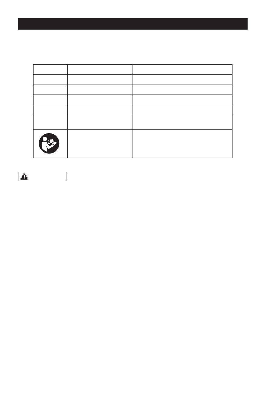
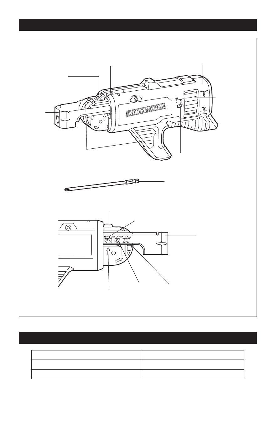
OVERVIEW
Release Button
Collated Screw Magazine
Screw-in Depth
Dial
Screw-in Depth
Indicator
Guide Rail for
Screw Belt
Shoe
Shoe
Screw-Length
Adjustment Button
Screw-Length Adjustment Button
6’’ Long Bit
Locking Pin
Arrow
Pin Slot Length Mark
SPECIFICATIONS
Collated Screw Length 1’’ - 2-1/8’’ (25-54 mm)
Collated Screw Size #6, #7 and #8
Magazine Weight (without bit) 1 lbs. (0.47 Kg)
NOTICE: Use only collated screws marked “CS Collated Screws” on the package. Other
screws are not compatible with this magazine.
Page 6
OPERATION
WARNING:
If any part is broken or
missing, DO NOT attach the battery pack
or operate the tool until the broken or
missing part is replaced. Failure to do so
could result in possible serious injury.
WARNING:
Do not attempt to
modify this tool or create accessories not
recommended for use with this tool. Any
such alteration or modification is misuse
and could result in a hazardous condition
leading to possible serious injury.
WARNING:
Your tool should
never be connected to the battery pack
when you are assembling parts, making
adjustments, cleaning, or when it is not in
use. Disconnecting the tool will prevent
accidental starting, which could cause
serious personal injury.
ASSEMBLY
PACKING LIST
– 6’’ PH2 long bit,
– collated screw magazine,
– instruction manual.
UNPACKING
1. Carefully remove the tool and any
accessories from the carton. Make sure
that all items listed in the packing list are
included.
2. Inspect the tool carefully to make sure
that no breakage or damage occurred
during shipping.
3. Do not discard the packing material
until you have carefully inspected and
satisfactorily operated the tool.
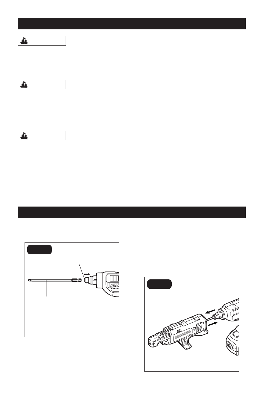
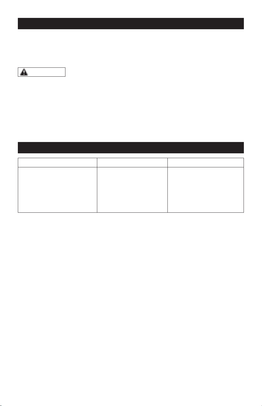
INSTALLING THE LONG BIT
(FIG. 1)
FIG. 1
6’’ Long Bit
Clutch
Hex Chuck
The 6” long bit is intended to be used with
the collated screw magazine.
1. Push the clutch towards the rear of the
tool as shown, insert the 6’’ long bit
into the hex chuck of the tool and then
release the clutch to lock the bit.
2. To remove the bit, push the clutch
towards the rear of the tool again.
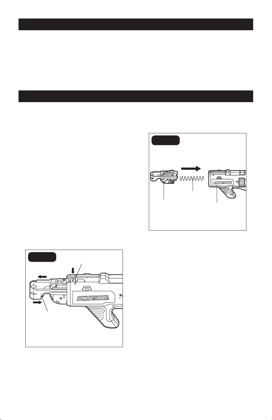
ATTACHING AND DETACHING
THE COLLATED SCREW
MAGAZINE (FIG. 2)
FIG. 2
Collated Screw
Magazine
“CLICK”
Page 7
1. With the long bit installed, feed the bit
and the hex chuck into the opening in
the back of the collated screw magazine
then push the collated screw magazine
onto the tool until it audibly “clicks” into
place.
2. To detach the collated screw magazine,
just pull the magazine off from the tool.
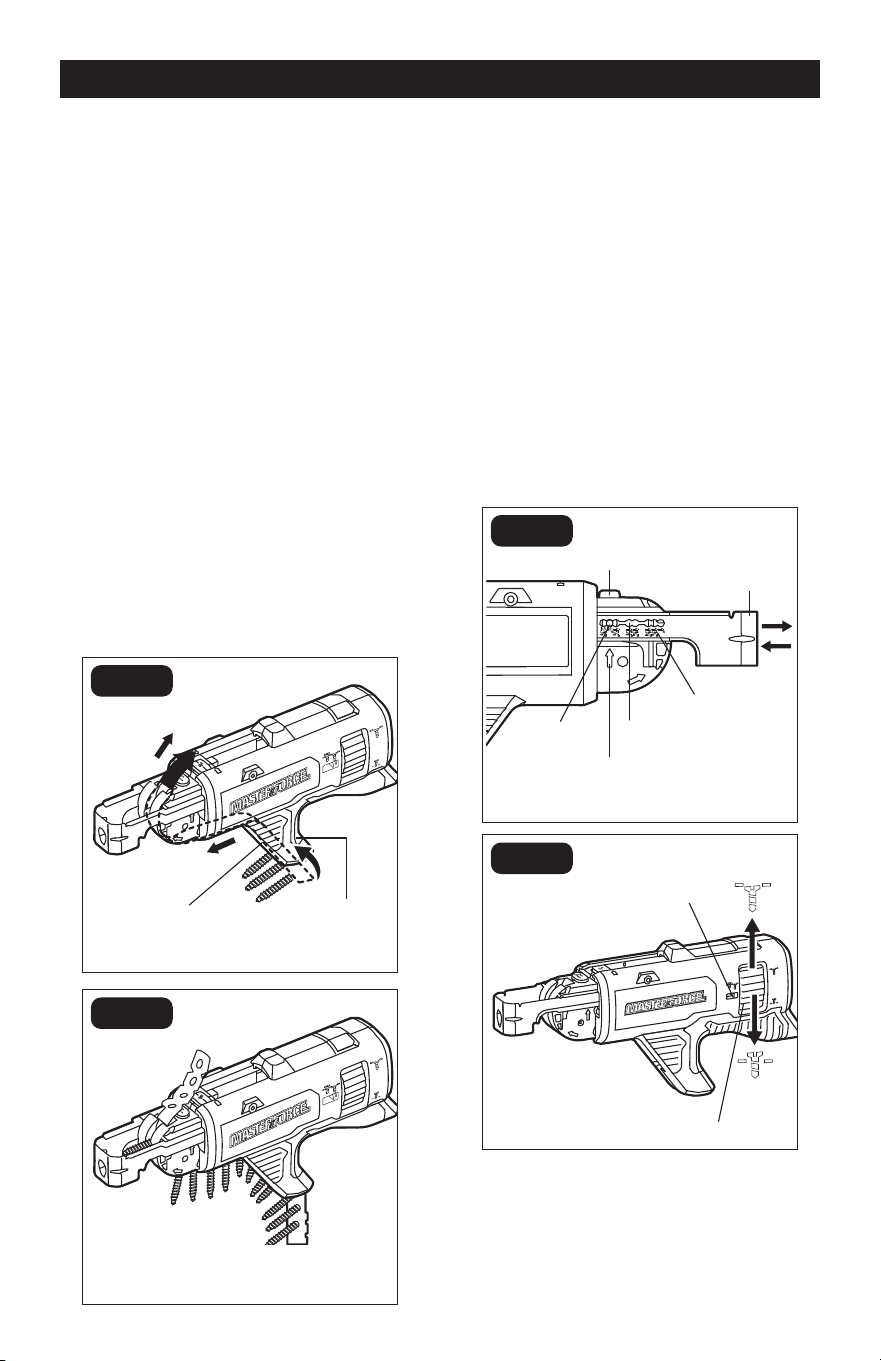
INSERTING AND REMOVING
COLLATED SCREW STRIP (FIG. 3)
NOTICE: Use only screw strips with screw
sizes #6, #7, and #8 with this magazine. Only
insert screw strips when the screw gun is
turned off and the trigger switch is locked.
Proper use of collated strips will reduce
the risk of injury, reduce jams and prevent
screws from damaging the workpiece. For
best performance, use new, undamaged
strips free of debris.
c
b
a
FIG. 3a
Advancing
Mechanism
Screw Guide
FIG. 3b
1. Take a collated strip, holding the plastic
portion, and feed from the bottom of the
screw guide and into the bottom of the
advancing mechanism.
2. Continue feeding the strip until the rst
screw is one slot below the driver bit.
3. To remove, pull the screw strip UP.
NOTICE: Do not remove the screw strip by
forcibly pulling the screw strip downwards
to avoid damaging the product or even
causing personal injury.
ADJUSTING SCREW-IN DEPTH
(FIG. 4)
FIG. 4a
Screw-Length
Adjustment Button
Shoe
Arrow
Locking
Pin
Pin Slot
Length Mark
FIG. 4b
Screw-in Depth
Indicator
Screw-in Depth Dial
NOTICE: Do not adjust the screw length
while a screw strip is in the magazine. Re-
move the screw strip prior to making adjust-
ments.
OPERATION
Page 8
OPERATION
This collated screw magazine is designed
for screws that are 1’’– 2-1/8’’ (25–54 mm)
long. Failure to set the correct screw
length can cause screws to not be driven
accurately which can result in the failure
to advance the next screw or screws not
being screwed-in properly.
The shoe has the specic length marks for
the most common screw lengths. The arrow
points at the length mark indicating the
current screw length (FIG. 4a). To set up the
magazine for a specic screw length:
1. Press the screw-length adjustment
button.
2. While the screw-length adjustment
button is depressed, pull the shoe out or
push it into the magazine until the arrow
is aligned with the desired length mark.
3. Release the locking button. Make sure
that the locking pin has fully seated in
the pin slot.
4. Use the screw-in depth dial to set the
desired screw-in depth. Turn the dial
up for driving the screws deeper into
the workpiece, or down to allow more
of the screw head to stick out from the
workpiece. The actual setting position is
shown in the screw-in depth indicator.
5. Upon setting, drive some screws for
testing and use the dial to adjust the
depth, if required.
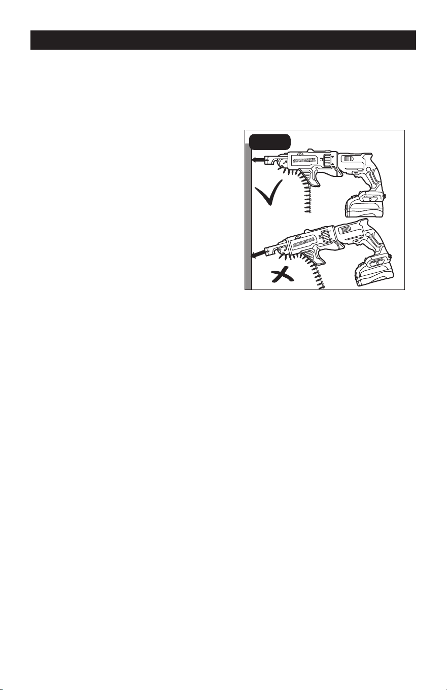
OPERATING INSTRUCTIONS
FOR USING COLLATED SCREW
MAGAZINE (FIG. 5)
Driving screws in:
FIG. 5
1. Adjust the magazine to the proper screw
length to match the screws being used
and load the screw strip.
2. Set the screw-in depth.
3. Set the direction of rotation to forward
rotation.
4. Grip electric power tool with both hands
on the handle and assume working
position.
5. Press the shoe against workpiece to
be screwed in place. Hold power tool
at right angles to workpiece surface
(FIG.5).
6. Depress and hold down the trigger
switch, then press the lock-on button to
lock the trigger switch on.
7. Push the screw gun against the
workpiece to drive the screw in. The
screw is screwed into the workpiece
until the set screw-in depth is reached.
Check screw-in depth, change if
required.
NOTE: When the preset screw-in depth is
reached, the drive is disengaged and the
screw gun bit stops turning while the motor
is still running.
Page 9
OPERATION
MAINTENANCE
8. Repeat the operation to drive more
screws.
9. When you have nished driving screws,
turn off the drywall screw gun.
10. Move the direction-of-rotation selector
to the middle position.
BEFORE EACH USE
1. Check for damaged, missing, or worn
parts.
2. Check for loose screws, misalignment
or binding of moving parts, or any other
condition that may affect the operation.
3. If abnormal vibration or noise occurs,
turn the tool off immediately and have
the problem corrected before further
use.
CLEANING THE COLLATED
SCREW MAGAZINE
(FIG. 6)
FIG. 6a
Shoe
c
b
Release Button
FIG. 6b
Advancing
Mechanism
Spring
Magazine
Enclosure
To remove dust and debris from the interior
of the magazine, follow the steps below:
1. Press the shoe towards the rear of the
magazine (a). While pressing the shoe on
place, press the release button (b) and
then pull out the advancing mechanism
from the magazine enclosure (c)
(FIG. 6a).
2. Take the spring out from the magazine
enclosure. Use compressed air to clean
the entire collated screw magazine.
3. To reassemble after cleaning, insert the
spring into the magazine enclosure and
then attach the shoe assembly onto the
enclosure (FIG. 6b).
a
Page 10
MAINTENANCE
STORAGE
Store the collated screw magazine indoors
in a place that is inaccessible to children.
Keep away from corrosive agents.
WARNING:
• When servicing, use only identical
replacement parts. Use of any other parts
may create a hazard or cause product
damage.
• To avoid serious personal injury,
always remove the battery pack from the
product when cleaning or performing any
maintenance.
• Avoid using solvents when cleaning
plastic parts. Most plastics are susceptible
to damage from various types of
commercial solvents and may be damaged
by their use. Use a clean cloth to remove
dirt, dust, oil, grease, etc.
• Using compressed air may be the most
effective cleaning method. Always wear
safety goggles when cleaning tools with
compressed air.
TROUBLESHOOTING
PROBLEM POSSIBLE CAUSE SOLUTION
The advancing mechanism
can’t be pulled out.
Incorrect steps taken.
While pressing the shoe
on place into the magazine
encloser, press the release
button and then pull out the
advancing mechanism from
the magazine enclosure.

Page 11
NOTES

Page 12
NOTES

Page 13
NOTES
SAVE YOUR RECEIPTS
THIS WARRANTY IS VOID WITHOUT THEM
COLLATED SCREW MAGAZINE ATTACHMENT
WARRANTY
90-DAY MONEY BACK GUARANTEE:
This MASTERFORCE
®
brand power tool carries our 90-DAY Money Back
Guarantee. If you are not completely satised with your MASTERFORCE
®
brand
power tool for any reason within ninety (90) days from the date of purchase, return
the tool with your original receipt to any MENARDS
®
retail store, and we will provide
you a refund – no questions asked.
3-YEAR LIMITED WARRANTY:
This MASTERFORCE
®
brand power tool carries our famous No Hassle 3-Year Limited
Warranty to the original purchaser. If, during normal use, this MASTERFORCE
®
power
tool breaks or fails due to a defect in material or workmanship within three (3) years
from the date of original purchase, simply bring this tool with the original sales receipt
back to your nearest MENARDS
®
retail store. At its discretion, MASTERFORCE
®
agrees
to have the tool or any defective part(s) repaired or replaced with the same or similar
MASTERFORCE
®
product or part free of charge, within the stated warranty period,
when returned by the original purchaser with original sales receipt. Not withstanding
the foregoing, this limited warranty does not cover any damage that has resulted from
abuse or misuse of the Merchandise. This warranty: (1) excludes expendable parts
including but not limited to blades, brushes, belts, bits, light bulbs, and/or batteries;
(2) shall be void if this tool is used for commercial and/or rental purposes; and (3) does
not cover any losses, injuries to persons/property or costs. This warranty does give you
specic legal rights and you may have other rights, which vary from state to state. Be
careful, tools are dangerous if improperly used or maintained. Seller’s employees are
not qualied to advise you on the use of this Merchandise. Any oral representation(s)
made will not be binding on seller or its employees. The rights under this limited
warranty are to the original purchaser of the Merchandise and may not be transferred
to any subsequent owner. This limited warranty is in lieu of all warranties, expressed
or implied including warranties or merchantability and tness for a particular purpose.
Seller shall not be liable for any special, incidental, or consequential damages. The
sole exclusive remedy against the seller will be for the replacement of any defects
as provided herein, as long as the seller is willing or able to replace this product or is
willing to refund the purchase price as provided above. For insurance purposes, seller
is not allowed to demonstrate any of these power tools for you.
For questions / comments, technical assistance or repair parts –
Please call toll free: 1-866-917-4374 (M-F 8:30am – 5:00pm EST).

09/2022
© 2022 Menard, Inc., Eau Claire, WI 54703
