Operator’s Manual
4-Volt Lithium-ion
Pivoting Screwdriver
Model No. 320.37810
Sears Brands Management Corporation, Hoffman Estates,
IL 60179 U.S.A.
www.craftsman.com
•WArrAnty
•SAfEty
•ASSEMBLy
•OpErAtIOn
•MAIntEnAnCE
•ESpAñOL
ѥWARNING: To reduce the risk of injury,
the user must read and understand the
Operator’s Manual before using this product.
Charge battery before rst use

Page 2 37810 Manual_Revised_13-0116
TABLE OF CONTENTS
Warranty Page 2
Safety Symbols Pages 4-5
Safety Instructions Pages 6-9
Description Pages 10-11
Assembly Page 12
Operation Pages 13-15
Maintenance Pages 16-17
Troubleshooting Page 17
Part List Pages 18-20
CRAFTSMAN ONE YEAR LIMITED WARRANTY
FOR ONE YEAR from the date of purchase, this product is warranted
against any defects in material or workmanship. With proof of purchase, a
defective product will be replaced free of charge.
For warranty coverage details to obtain free replacement, visit the web
site: www.craftsman.com
This warranty does not cover the bit, which is an expendable part that can
wear out from normal use within the warranty period.
This warranty is void if this product is ever used while providing commercial
services or if rented to another person.
This warranty gives you specic legal rights, and you may also have other
rights which vary from state to state.
Sears Brands Management Corporation, Hoffman Estates, IL 60179
This pivoting screwdriver has many features for making its use more pleasant
and enjoyable. Safety, performance, and dependability have been given top
priority in the design of this product, making it easy to maintain and operate.
SAVE THESE INSTRUCTIONS!
READ ALL INSTRUCTIONS!

37810 Manual_Revised_13-0116 Page 3
ѥDANGER: People with electronic devices, such as pacemakers, should
consult their physician(s) before using this product. Operation of electrical
equipment in close proximity to a heart pacemaker could cause interference or
failure of the pacemaker.
ѥWARNING: Some dust created by power sanding, sawing, grinding, drilling
and other construction activities contains chemicals known to the State of
California to cause cancer, birth defects or other reproductive harm. Some
examples of these chemicals are:
• Lead from lead-based paints,
• Crystalline silica from bricks and cement and other masonry products, and
• Arsenic and chromium from chemically-treated lumber.
Your risk from these exposures varies, depending on how often you do this type
of work. To reduce your exposure to these chemicals: work in a well ventilated
area and work with approved safety equipment, such as dust masks that are
specially designed to lter out microscopic particles.

Page 4 37810 Manual_Revised_13-0116
SAFETY SYMBOLS
The purpose of safety symbols is to attract your attention to possible dangers.
The safety symbols and the explanations with them deserve your careful
attention and understanding. The symbol warnings do not, by themselves,
eliminate any danger. The instructions and warnings they give are no substitutes
for proper accident prevention measures.
ѥWARNING: Be sure to read and understand all safety instructions in this
manual, including all safety alert symbols such as “DANGER,” “WARNING,” and
“CAUTION” before using this screwdriver. Failure to follow all instructions listed
in this manual may result in electric shock, fire and/or serious personal injury.
SYMBOL SIGNAL MEANING
SAFETY ALERT SYMBOL: Indicates DANGER, WARNING, OR CAUTION; may
be used in conjunction with other symbols or pictographs.
ѥDANGER: Indicates a hazardous situation which, if not avoided, will result in
death or serious injury.
ѥWARNING: Indicates a hazardous situation which, if not avoided, could
result in death or serious injury.
ѥCAUTION: Indicates a hazardous situation which, if not avoided, could
result in minor or moderate injury.
Damage Prevention and Information Messages
These inform the user of important information and/or instructions that could
lead to equipment or other property damage if they are not followed. Each
message is example below:
NOTICE: Equipment and/or property damage may result if these instructions are
not followed.
ѥWARNING: To ensure safety and reliability, all repairs should be performed
by a qualified service technician.
WARNING: The operation of any power tools can result in
foreign objects being thrown into your eyes, which can result in
severe eye damage. Before beginning power tool operation,
always wear safety goggles or safety glasses with side shield
and a full face shield when needed. We recommend a Wide
Vision Safety Mask for use over eyeglasses or standard safety
glasses with side shields. Always use eye protection which is
marked to comply with ANSI Z87.1.
37810 Manual_Revised_13-0116 Page 5
SAVE THESE INSTRUCTIONS
Some of these following symbols may be used on this tool. Please study them
and learn their meaning. Proper interpretation of these symbols will allow you to
operate the tool better and more safely.
V Volts Voltage
A Amperes Current
Hz Hertz Frequency (cycles per second)
W Watt Power
min Minutes Time
Alternating Current Type of current
Direct Current Type or a characteristic of current
No Load Speed Rotational speed, at no load
Class II Construction Double-insulated construction
.../min Per Minute
Revolutions, strokes, surface speed,
orbits, etc. per minute
Wet Conditions Alert
Do not expose to rain or use in damp
locations.
Read The Operator’s Manual
To reduce the ri
sk of injury, user must
re
ad and understand operator’s manual
before using this product.
Eye Protection
Always wear safety goggles or safety
glasses with side shields and a full face
shield when operating this product.
Safety Alert Precautions that involve your safety.
No-Hands Symbol
Failure to keep your hands away from the
blade will result in serious personal injury.
No-Hands Symbol
Failure to keep your hands away from the
blade will result in serious personal injury.
No-H
ands Symbol
Failure to keep your hands away f
rom the
blade will result in serious personal injury.
No-Hands Symbol
Failure to keep your hands away from the
blade will result in serious personal injury.
Hot Surface
To reduce the risk of injury or damage,
avoid contact with any hot surface.
SYMBOL NAME DESIGNATION/EXPLANATION

Page 6 37810 Manual_Revised_13-0116
SAFETY INSTRUCTIONS
GENERAL POWER TOOL SAFETY WARNINGS
ѥWARNING: Read all safety warnings and instructions. Failure to follow
the warnings and instructions listed below may result in electric shock, fire, and/
or serious personal injury.
Save all warnings and instructions for future reference.
The term “power tool” in all warnings listed below refers to corded power tools
or battery-operated (cordless) power tools.
WORK AREA SAFETY
• Keep your work area clean and well lit. Cluttered or dark areas
invite accidents.
• Do not operate power tools in explosive environments, such as in the
presence of flammable liquids, gases, or dust. Power tools create sparks,
which may ignite the dust or fumes.
• Keep children and bystanders away while operating a power tool.
Distractions may cause you to lose control.
ELECTRICAL SAFETY
• Power tool plugs must match the outlet. Never modify the plug in
any way. Do not use any adapter plugs with grounded power tools.
Unmodified plugs and matching outlets will reduce the risk of electric shock.
• Avoid body contact with grounded surfaces, such as pipes, radiators,
ranges, and refrigerators. There is an increased risk of electric shock if
your body is grounded.
• Do not expose power tools to rain or wet conditions. Water entering a
power tool will increase the risk of electric shock.
• Do not abuse the cord. Never use the cord for carrying, pulling, or
unplugging the power tool. Keep the cord away from heat, oil, sharp
edges, or moving parts. Damaged or entangled cords increase the risk of
electric shock.
• When operating a power tool outdoors, use an extension cord suitable
for outdoor use. Use of a cord suitable for outdoor use reduces the risk of
electric shock.
• If operating a power tool in a damp location is unavoidable, use a
ground fault circuit interrupter (GFCI) protected supply. Use of a (GFCI)
reduces the risk of electric shock.

37810 Manual_Revised_13-0116 Page 7
PERSONAL SAFETY
• Stay alert, watch what you are doing and use common sense when
operating a power tool. Do not use the tool while tired or under the
influence of drugs, alcohol, or medication. A moment of inattention while
operating power tools may result in serious personal injury.
• Use personal protective equipment. Always wear eye protection. Protective
equipment such as dust mask, non-skid safety shoes, hard hat, or hearing
protection used for appropriate conditions will reduce personal injuries.
• Prevent unintentional starting. Ensure that the switch is in the OFF-
position before connecting to a power source and/or battery, picking
up or carrying the tool. Carrying power tools with your finger on the switch
or energizing power tools that have the switch on invites accidents.
• Remove any adjusting key or wrench before turning the power tool
on. A wrench or a key left attached to a rotating part of the power tool may
result in personal injury.
• Do not overreach. Keep proper footing and balance at all times. This
enables better control of the power tool in unexpected situations.
• Dress properly. Do not wear loose clothing or jewelry. Keep your hair,
clothing and gloves away from moving parts. Loose clothes, jewelry or
long hair can be caught in moving parts.
• If devices are provided for the connection of dust extraction and
collection facilities, ensure that these are connected and properly used.
Use of these devices can reduce dust-related hazards.
POWER TOOL USE AND CARE
• Do not force the power tool. Use the correct power tool for your
application. The correct power tool will do the job better and more safely at
the rate for which it was designed.
• Do not use the power tool if the switch does not turn it on and off. Any
power tool that cannot be controlled with the switch is dangerous and must
be repaired.
• Disconnect the plug from the power source and/or the battery from the
power tool before making any adjustments, changing accessories, or
storing power tools. Such preventive safety measures reduce the risk of
starting the power tool accidentally.

Page 8 37810 Manual_Revised_13-0116
• Store idle power tools out of the reach of children and do not allow
persons unfamiliar with the power tool or these instructions to operate
the power tool. Power tools are dangerous in the hands of untrained users.
• Maintain power tools. Check for misalignment or binding of moving
parts, breakage of parts and any other condition that may affect the
power tool operation. If damaged, have the power tool repaired before
use. Many accidents are caused by poorly maintained power tools.
• Keep cutting tools sharp and clean. Properly maintained cutting tools with
sharp cutting edges are less likely to bind and are easier to control.
• Use the power tool, accessories and tool blades etc., in accordance
with these instructions, taking into account the working conditions and
the work to be performed. Use of the power tool for operations different
from those intended could result in a hazardous situation.
BATTERY TOOL USE AND CARE
• Recharge only with the charger specified by the manufacturer. A
charger that is suitable for one type of battery pack may create a risk of fire
when used with another battery pack.
• Use power tools only with specifically designated battery packs. Use of
any other battery packs may create a risk of injury and fire.
• When the battery pack is not in use, keep it away from other metal
objects, such as paper clips, coins, keys, nails screws, or other
small metal objects that can make a connection from one terminal to
another. Shorting the battery terminals together may cause burns or a fire.
• Under abusive conditions, liquid may be ejected from the battery;
avoid contact. If contact accidentally occurs, ush with water. If liquid
contacts eyes, also seek medical help. Liquid ejected from the battery
may cause irritation or burns.

37810 Manual_Revised_13-0116 Page 9
SERVICE
• Have your power tool serviced by a qualified repair person using only
identical replacement parts. This will ensure that the safety of the power
tool is maintained.
• Follow instructions in the Maintenance section of this manual. Use of
parts not listed in this manual or failure to follow Maintenance instructions
may create a risk of shock or injury.
SPECIFIC SAFETY RULES FOR PIVOTING SCREWDRIVER
• Hold the power tool by the insulated gripping surfaces when
performing an operation where the fastener may contact hidden wiring.
Fasteners contacting a live wire may make exposed metal parts of the
power tool live and could give the operator an electric shock.
• Secure the workpiece. Clamping devices or a vise will hold the workpiece
in place better than the hand.
• Always wait until the machine has come to a complete stop before
placing it down. The tool insert can jam and lead to loss of control over the
power tool.
• Before performing any kind of work on the machine (e.g., maintenance,
tool change, etc.), as well as when transporting and storing it, always
set the lock-off slide at the locked position. Unintentional activation of
the On/Off switch may result in personal injury.
• Use protective gloves when removing the bit from the tool, or first
allow the clamp to cool down. The bit may be hot after prolonged use.
• Protect the battery from heat and fire. There is risk of explosion.
Page 10 37810 Manual_Revised_13-0116
DESCRIPTION
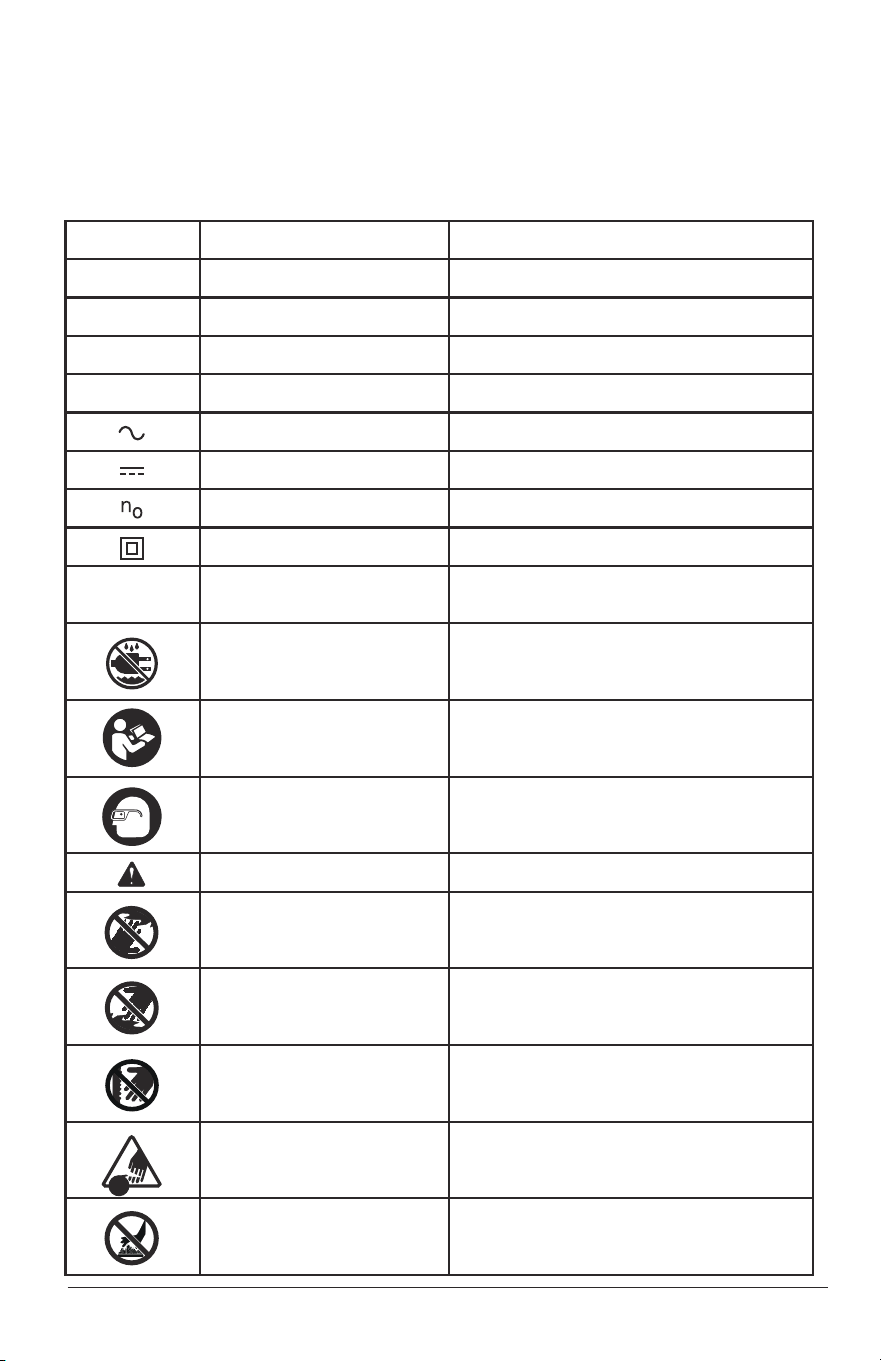
KNOW YOUR PIVOTING SCREWDRIVER (Fig. 1)
PRODUCT SEPCIFICATIONS
Motor 4 Volt DC
No Load Speed 200 RPM
Max Torque 26-1/2 in.lbs.
Tool Weight 0.88 lbs
Bit collet 1/4 in. hex collect
Battery Voltage 4 Volt DC
Charging Time 5-7 hours
Power Unit
Input: 120V AC 60Hz
Output: 6.0V DC 300mA
ѥWARNING: The safe use of this product requires an understanding of the
information on the tool and in this operator’s manual, as well as knowledge of
the project you are attempting. Before use of this product, familiarize yourself
with all operating features and safety rules.
Fig. 1
Forward/Reverse
switch
LED Worklight
Charging socket
Power Unit
Power Unit jack
Charging Indicator
Bit Collet
Lock-off slide

37810 Manual_Revised_13-0116 Page 11
FORWARD/REVERSE SWITCH
Forward/Reverse Switch – controls the direction of the rotation.
LED WORKLIGHT
The LED worklight is located on the front of the screwdriver. This feature
provides extra light for increased visibility.
PIVOT HANDLE
The pivot handle will lock in two different positions to allow user the most
comfort and control possible.
1/4" HEX COLLET
The 1/4 in. hex collet will accept all hex-shank bits; the wire retainer inside the
collet holds the bit in place.

Page 12 37810 Manual_Revised_13-0116
ASSEMBLY
ѥWARNING: If any parts are broken or missing, do not operate the tool until the
broken or missing parts are replaced. Failure to do so could result in serious injury.
ѥWARNING: Do not attempt to modify this screwdriver or create accessories
not recommended for use with this screwdriver. Any such alteration or
modification is misuse and could result in a hazardous condition, leading to
serious injury.
ѥWARNING: To prevent accidental starting that could cause serious personal
injury, always slide the lock-off slide to the locked position when assembling parts.
UNPACKING
When unpacking the box, do not discard any packing materials until all of the
contents are accounted for.
1. Carefully lift the screwdriver out of carton and place it on a stable, at surface.
2. Open the carton to locate the following:
• Pivoting screwdriver
• Power unit
• 1 in. Philips head bit
• Manual
3. Inspect the items carefully to make sure that no breakage or damage has
occurred during shipping. If any of the items is missing or damaged, return
the tool to the store where purchased for replacement.
37810 Manual_Revised_13-0116 Page 13
OPERATION
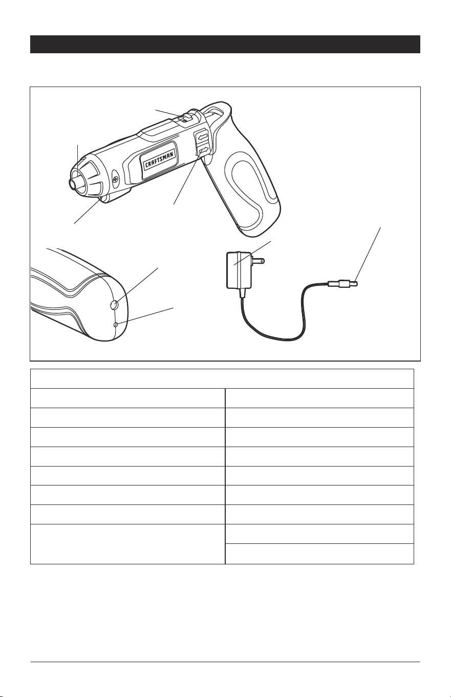
HOW TO CHARGE THE
SCREWDRIVER (Fig. 2)
To protect your new rechargeable
screwdriver from possible damage,
the battery is in a low-charge
condition when initially shipped.
Insert the power unit jack into
the charging socket, making sure
that it is properly connected.
The power unit can be used with
normal household current: 120
volts, 60 Hz, AC only. Connect the
power unit plug to an electrical outlet.
The indicator light on the screwdriver initially shines red when the power unit is
plugged into a power source and will shine green when the battery is fully charged.
Charge the battery for at least 7 hours before the rst use.
NOTICE: For best results, do not recharge the battery for less than 5 hours or
more than 7 hours after each use.
Do not place the power unit in an area of extreme heat or cold. It works best at
normal room temperature. The screwdriver or power unit may become warm
during charging. This is normal.
INSERTING AND REMOVING
SCREWDRIVER BITS (Fig. 3 )
Inserting the bit
Place the bit directly into the
screwdriver collet; the wire
retainer inside the collet holds the
bit in place.
NOTICE: Your screwdriver is
intended for light-duty use. For best
results, 1⁄4 in. hex screwdriver bits
are recommended.
Removing the bit
Pull the bit forcibly to remove it from the tool.
ѥWARNING: Always set the lock-off slide to the locked position ( ) , when
inserting or removing the bit.
Fig. 2
Fig. 3
Charging
socket
Charging
indicator
Power unit
jack
Page 14 37810 Manual_Revised_13-0116
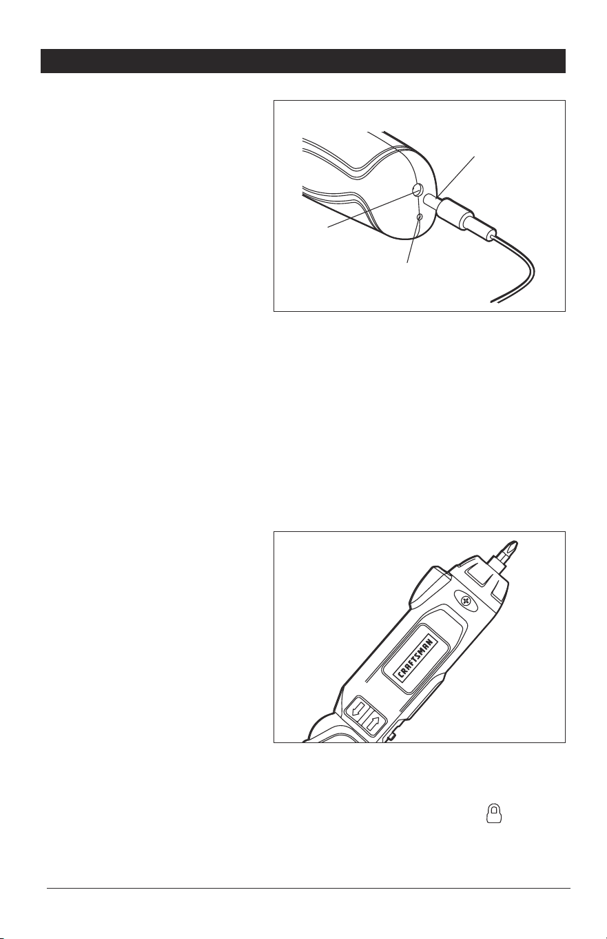
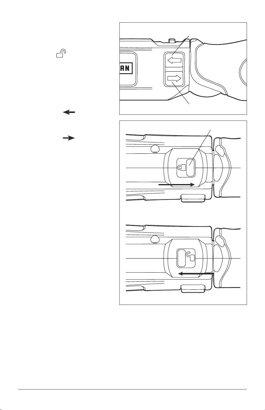
FORWARD/REVERSE
SWITCH (Fig. 4)
1. Push the lock-off slide
forward ( ) to unlock the
tool (Fig. 4a).
2. Depress the forward/reverse
switch to turn on the tool. The
switch can also determine the
direction of rotation of the tool.
3. To select forward rotation,
press the “ ” side of the
rocker switch.
4. To select the reverse rotation,
press the “ ” side of the
rocker switch.
Fig. 4
Fig. 4a
locked
unlocked
Forward Switch
Reverse Switch
Lock-off slide
37810 Manual_Revised_13-0116 Page 15
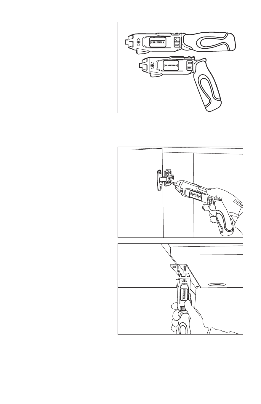
GRIPPING THE
SCREWDRIVER (Fig. 5)
Determine the best grip for your
job according to the working
conditions (Fig. 5).
As the handle is pivoted to the
desired position, you will hear a
“click” to indicate the handle has
been locked.
ѥWARNING: Never place your
finger near the the hinge when
pivoting the handle. Doing so can
result in your finger being pinched
or cut.
TIGHTEN/LOOSEN THE
SCREW (Figs. 6 and 7)
1. Install the correct bit.
2. Select Forward rotation to
tighten or Reverse rotation
to loosen.
3. Lock in the best grip angle
for your job.
4. Apply just enough pressure
to the screw to keep the bit
engaged on the screw.
5. Turn on the screwdriver to
tighten or loosen the screw.
Fig. 5
Fig. 6
Fig. 7

Page 16 37810 Manual_Revised_13-0116
MAINTENANCE
GENERAL MAINTENANCE
Avoid using solvents when cleaning plastic parts. Most plastics are susceptible
to damage from various types of commercial solvents and may be damaged by
their use. Use clean cloth to remove dirt, dust, oil, grease, etc.
ѥWARNING: Do not at any time allow brake fluids, gasoline, petroleum-based
products, penetrating oils, etc. to come in contact with plastic parts. Chemicals can
damage, weaken or destroy plastic which may result in serious personal injury.
ѥWARNING: When servicing, use only identical replacement parts. Use of any
other parts may create a hazard or cause product damage. To ensure safety and
reliability, all repairs should be performed by a qualified service technician.
BATTERIES:
The screwdriver is equipped with Lithium-Ion rechargeable batteries. The
duration of use from each charge will depend on the type of work performed.
The batteries in this tool have been designed to provide maximum trouble-free
life. Like all batteries, they will eventually wear out. Do not attempt to replace the
batteries. Handling of the batteries, especially when wearing rings and jewelry
could result in a serious burn.
To obtain the longest possible battery life, read and understand the operator’s
manual. It is good practice to unplug the Charger/Adapter.
For Lithium-Ion battery storage longer than 30 days:
• Store the Lithium-Ion battery where the temperature is below 80°F (26°C)
and free of moisture.
• Store Lithium-Ion battery in a 30%-50% charged condition.
• Every six months of storage, fully charge the Lithium-Ion battery.
• Exterior may be cleaned with a cloth or soft non-metallic brush.

37810 Manual_Revised_13-0116 Page 17
BATTERY REMOVAL AND PREPARATION
FOR RECYCLING
To preserve natural resources, please recycle or
dispose of batteries properly. This product contains
lithium-ion battery. Local, state, or federal laws
may prohibit disposal of lithium-ion batteries in
ordinary trash. Consult your local waste authority
for information regarding available recycling and/or
disposal options.
ѥWARNING: Upon removal of the battery for disposal or recycling, cover the
battery terminals with heavy-duty adhesive tape. Do not attempt to destroy or
disassemble the battery or remove any of its components. Lithium-Ion batteries
must be recycled or disposed of properly. Also, never touch the terminals with metal
objects and/or body parts as a short circuit may result. Keep away from children.
Failure to comply with these warnings could result in fire and/or serious injury.
TROUBLESHOOTING
PROBLEM CAUSE SOLUTION
The screwdriver does
not work
Battery is depleted Charge the battery
Bit cannot be installed
Bit does not t the
bit collet
Use suitable bit
Page 18 37810 Manual_Revised_13-0116
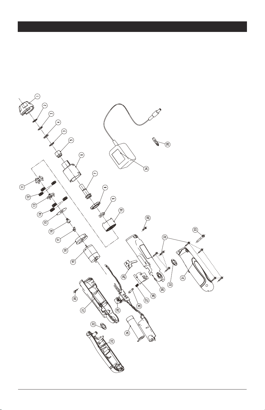
PART LIST
4-VOLT PIVOTING SCREWDRIVER MODEL NO. 320.37810
The Model Number will be found on the Nameplate attached to the body of
the screwdriver. Always mention the Model Number when ordering parts for
this tool.
To order parts, call 1-800-469-4663.

37810 Manual_Revised_13-0116 Page 19
PART LIST
4-VOLT PIVOTING SCREWDRIVER MODEL NO. 320.37810
The Model Number will be found on the Nameplate attached to the body of
the screwdriver. Always mention the Model Number when ordering parts for
this tool.
To order parts, call 1-800-469-4663.
No Part No Part Name QTY
1 3120817000 Front Housing 1
2 3700438000 "C"Ring 1
3 3700436000 Gasket 2
4 5700047000 Steel Ball 15
5 3520110000 Bush 1
6 3120814000 Gear Box 1
7 2820539000 Spindle Set 1
8 3520109000 Outer Bracket 1
9 3550294000 Lock Pin 6
10 3520107000 Internal Gear 1
11 3520108000 Planet Gear Bracket 1
12 3520105000 Planet Gear 3
13 3520106000 Turntable 1
14 3120816000 Plastic Gear 3
15 3700435000 Gasket 1
16 3520112000 Pinion 1
17 5620182000 Tapping Screw 2
18 3120815000 Motor Cover 1
19 2730006000 Motor 1
20 5620181000 Tapping Screw 2
21 3126509000 Left Housing 1
22 3705233000 Washer 2
23 2823366000 Left Handle Assembly 1
24 2770240000 Battery 1
25 4890906000 PCB Assembly 1

Page 20 37810 Manual_Revised_13-0116
No Part No Part Name QTY
26 3126514000 Lock Pin 1
27 3660539000 Compression Spring 1
28 3126512000 Switch Support 1
29 3126513000 Lock Button 1
30 3126510000 Right Housing 1
31 2823365000 Right Handle Assembly 1
32 5610008000 Tapping Screw 7
33 5610034000 Tapping Screw 1
34 0800116000 Charger 1
35 3810102000 Screw Bit 1