
40 41 42 43
44 45 46 47
15
48 49 50
51 52
18
55
20
2 9
29 30
19
MILWAUKEE ELECTRIC TOOL CORPORATION
13135 W. Lisbon Road, Brookfi eld, WI 53005
Drwg. 5
6140-30
54-38-1770
B69A
4.5" ANGLE GRINDER with PADDLE SWITCH w/Lock-Off
REVISED BULLETIN
DATE
Oct. 2012
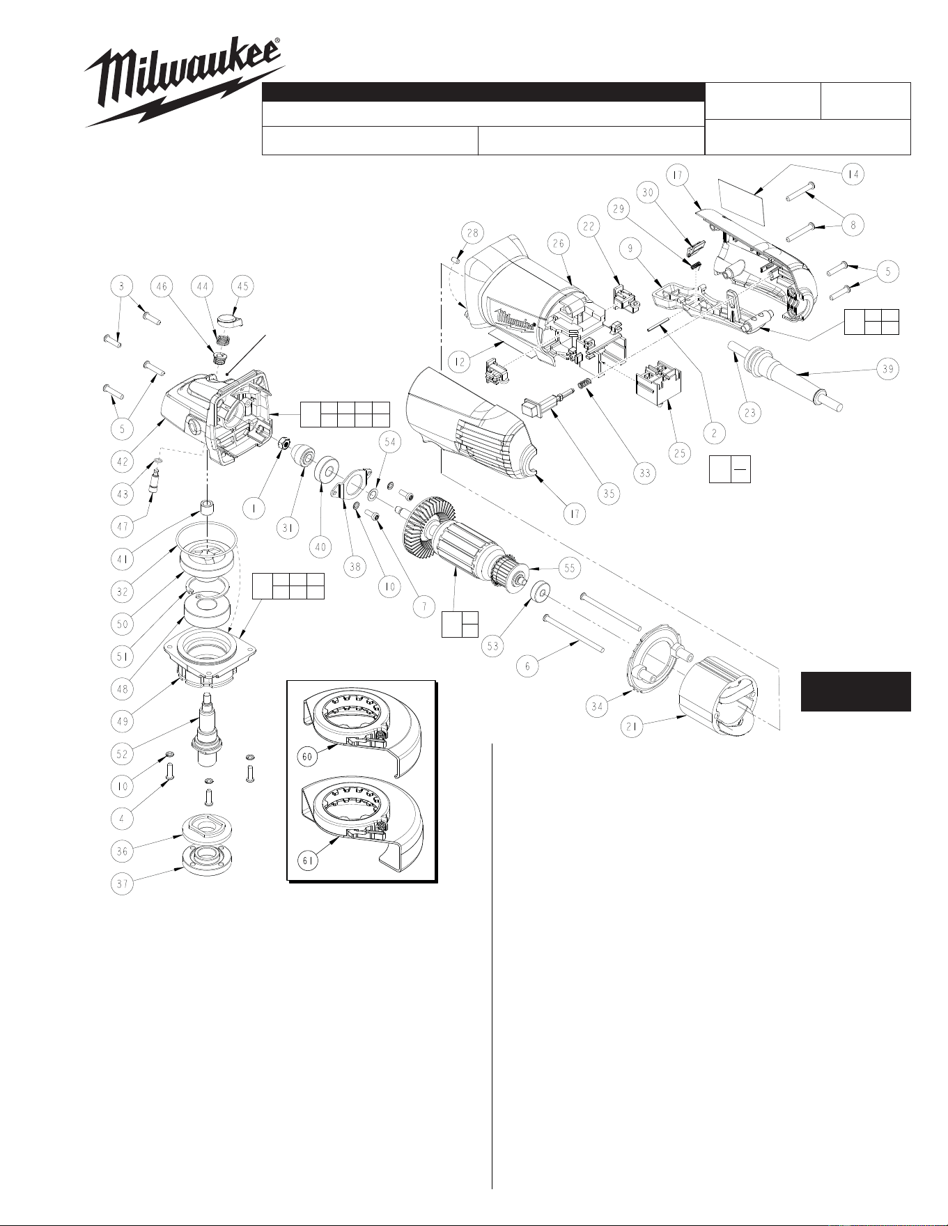
SERVICE PARTS LIST
BULLETIN NO.
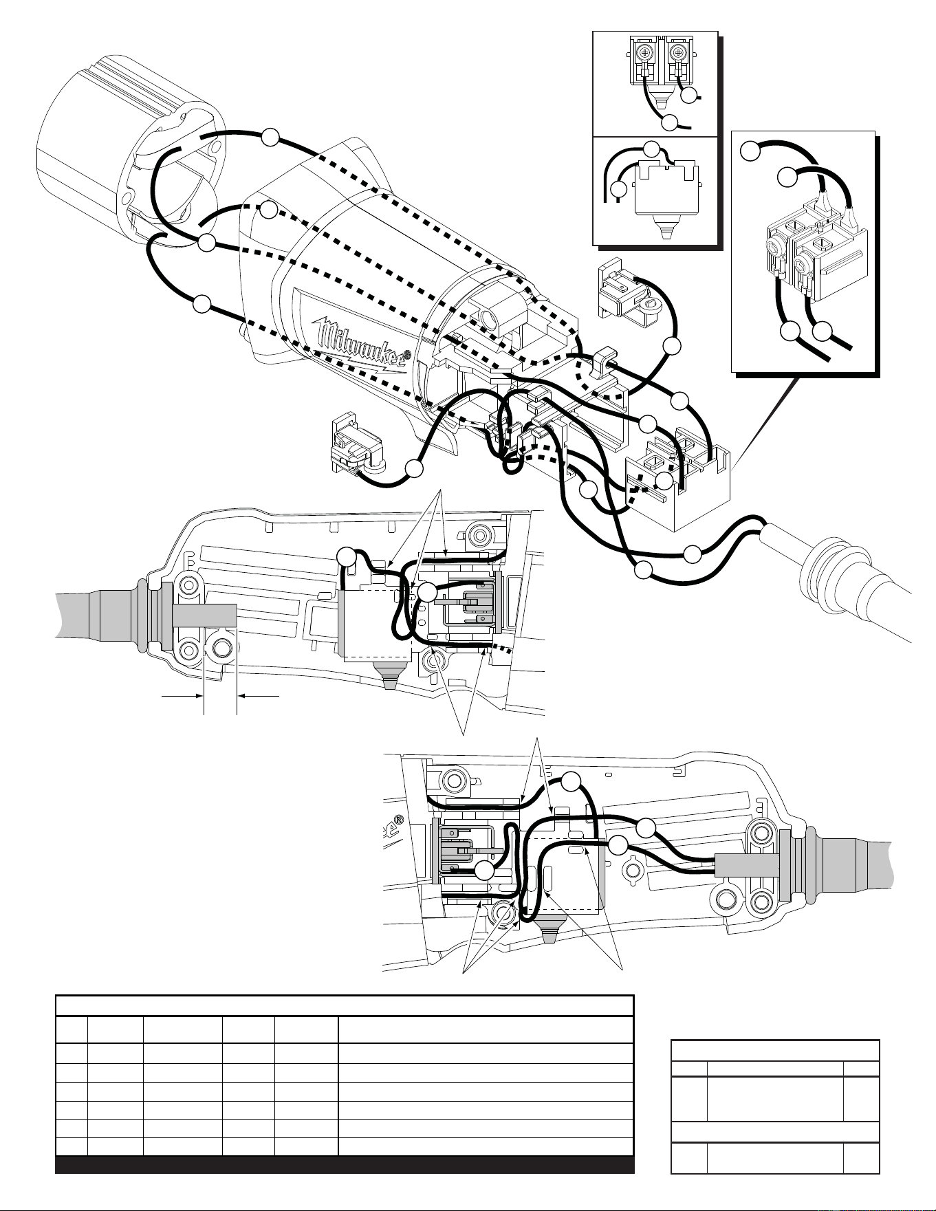
WIRING INSTRUCTION
CATALOG NO.
SPECIFY CATALOG NO. AND SERIAL NO. WHEN ORDERING PARTS
STARTING
SERIAL NUMBER
FIG. PART NO. DESCRIPTION OF PART NO. REQ.
1 05-55-0620 M5 Hex Nut (1)
2 06-65-1280 Pin (1)
3 05-88-1200 M4 x 16 T-20 Screw (2)
4 05-88-1210 M4 x 14 T-20 Screw (4)
5 05-88-1250 M4 x 20 T-20 Screw (4)
6 05-88-1275 M4 x 70 Screw (2)
7 05-88-1280 M4 x 10 T-20 Screw (2)
FIG. PART NO. DESCRIPTION OF PART NO. REQ.
8 05-88-1300 M4 x 28 T-20 Screw (2)
9 31-92-0420 Paddle (1)
10 05-90-0225 M4 Lock Washer (6)
12 10-15-1230 Warning Label (1)
14 12-20-6116 Service Nameplate (1)
15 14-29-0300 Gearcase Assembly (1)
17 14-34-0710 Rear Handle Assembly (1)
18 14-73-0400 Spindle/Hub Assembly (1)
19 14-78-0500 Paddle Assembly (1)
20 16-10-7005 Service Armature Assembly (1)
21 18-07-2290 Service Field (1)
22 22-22-1560 Carbon Brush Assembly (2)
23 22-64-2020 Cord (1)
25 23-66-2665 Switch (1)
26 31-50-2170 Motor Housing (1)
28 31-53-0240 Rubber Slug (1)
29 40-50-1480 Torsion Spring (1)
30 42-42-0620 Lock-Off Button (1)
31 32-60-1390 Bevel Pinion (1)
32 34-40-0560 O-Ring (1)
33 40-50-1625 Lock-On Spring (1)
34 42-14-0475 Fan Baffl e (1)
EXAMPLE:
Component Parts (Small #)
Are Included When Ordering
The Assembly (Large #).
0
00
See Reverse Side
FIG. PART NO. DESCRIPTION OF PART NO. REQ.
35 42-42-0660 Lock-On Button (1)
36 43-34-0036 Inner Disk Flange (1)
37 44-40-0035 Outer Flange Nut (1)
38 44-66-0450 Bearing Retainer (1)
39 44-76-0210 Strain Relief (1)
40 02-04-0620 Ball Bearing (1)
41 02-50-1195 Needle Bearing (1)
42 28-14-0710 Gearcase (1)
43 34-40-0450 O-Ring (1)
44 40-50-1330 Compression Spring (1)
45 42-42-0575 Spindle Lock Button (1)
46 42-42-0580 Spindle Lock Tube (1)
47 42-60-1190 Spindle Lock Pin (1)
48 02-04-1150 Ball Bearing (1)
49 28-53-0400 Lower Gearcase Hub (1)
50 32-05-1090 Bevel Gear (1)
51 34-80-2275 Retaining Ring (1)
52 38-50-1275 Spindle (1)
53 02-04-2110 Ball Bearing (1)
54 45-88-0406 Washer (1)
55 43-86-0010 Insulation Disc (1)
60 43-54-1070 4.5" T27 Guard Assembly (Standard) (1)
61 43-54-1090 4.5" T1 Guard Assembly (Optional) (1)
42-62-0100 Side Handle (Not Shown) (1)
49-96-7205 Spanner Wrench (Not Shown) (1)
FIG. LUBRICATION (*See lubrication note above):
31,50 Type "Y" Grease, No. 49-08-5270, Must Be Applied
To All Gear Teeth.
32,42 Lightly coat with grease O-Ring and bearing bore in Gearcase.
42 .3 -.4 Ounces (9-12 Grams) Type "Y" Grease, No. 49-08-5270.
Functionally check Spindle
Lock mechanism. Spindle
Lock Pin (47) must return
briskly when released from
engagement in Gear (50).
NOTE:
Torque Armature Nut (1)
to 47 in/lbs, 55 kg/cm.
Orient the Needle
Bearing (41) such that
side with vendor I.D. is
facing the Gear (50).
Rubber Slug (28) to be placed
in cavity by bearing bore
in the back of Motor
Housing (26).
* LUBRICATION NOTE: When servicing the Gears (31
& 50) or the Gearcase (42), 90-95% of the old grease
must be removed prior to new grease being added.
Orient Insulation Disc (55) with shoulder facing
Ball Bearing (53) as shown. Exercise
caution when installing. Make sure
that the Insulation Disc rests
against commutator bars with
no visable gap.
SEE NEXT PAGE
FOR ADDITIONAL
SERVICE NOTES
(Standard)
(Optional)
6
6
2
1
5
5
3
3
4
4
BLACK
WHITE
YELLOW
YELLOW
WHITE
RED
1
2
BULK LEAD WIRE - BULLETIN 58-01-0003
WIRING SPECIFICATIONS
Wire Wire Origin or
No. Color Part No. Gauge Length Terminals, Connectors and End Wire Preparation
1 White 22-64-2020 -- -- Component of cord set.
2 Black 22-64-2020 -- -- Component of cord set.
3 Yellow 18-07-2290 -- -- Component of fi eld.
4 Yellow 18-07-2290 -- -- Component of fi eld.
5 White 18-07-2290 -- -- Component of fi eld.
6 Red 18-07-2290 -- -- Component of fi eld.
Qnty.
TERMINAL DESCRIPTION
Part No.Code
NOTE:
All leads must be held to ± 1/16".
All lead lengths are before stripping.
CONNECTOR DESCRIPTION
BE CAREFUL AND AVOID PINCHING
WIRES BETWEEN HANDLE HALVES
WHEN ASSEMBLING.
AS AN AID TO REASSEMBLY, TAKE NOTICE OF
WIRE ROUTING AND POSITION IN WIRE GUIDES
AND TRAPS WHILE DISMANTLING TOOL.
3
1
2
5
Traps
Traps
Traps
6
4
Extend cord jacket
approx. 1/4” past
cord clamp.
Traps
Traps
2
4
3
1
4
3
2
1
FRONT
VIEW OF
SWITCH
BACK
VIEW OF
SWITCH