
54-38-1641
58-01-1375
B46B
6089-31
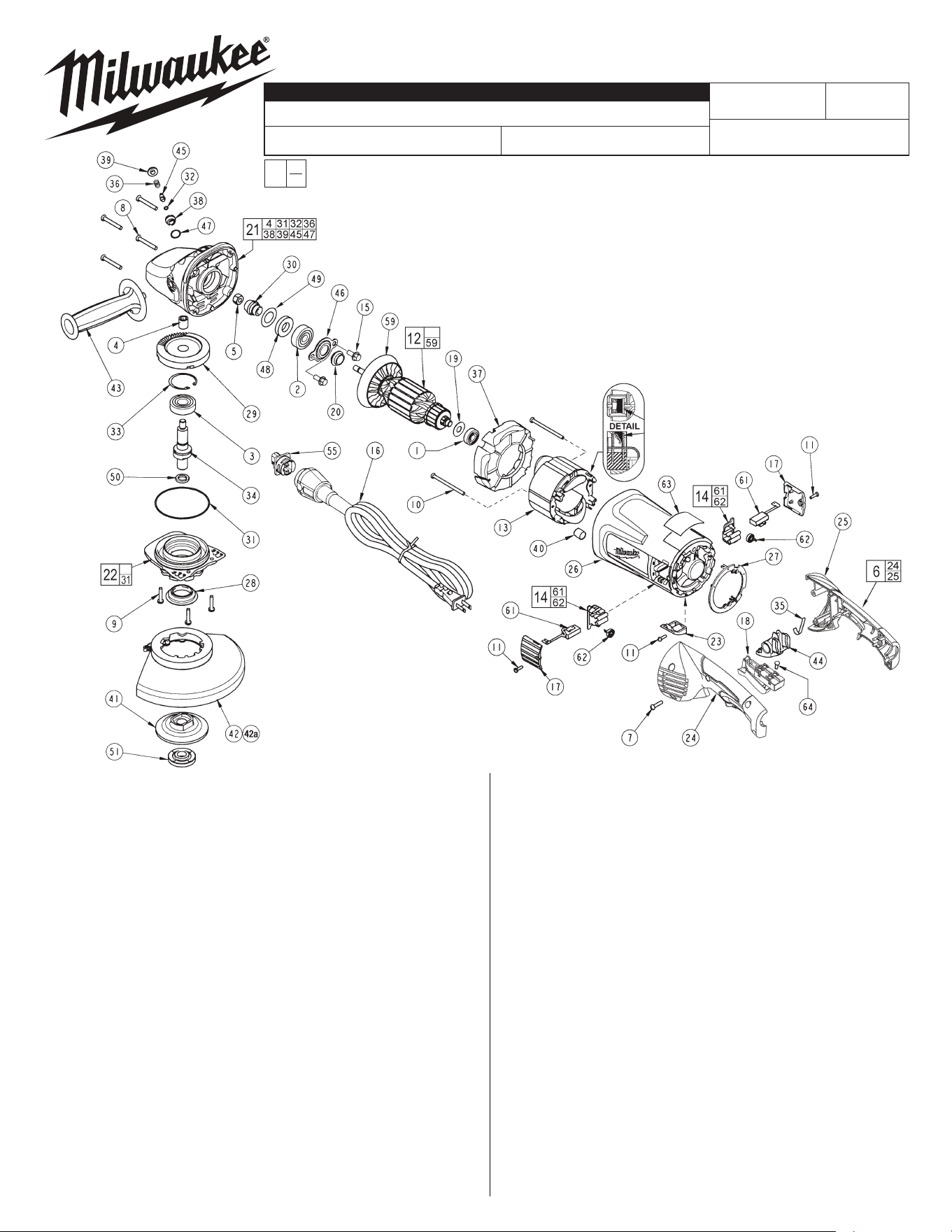
FIG. PART NO. DESCRIPTION OF PART NO REQ.
)1( gniraeB llaB 5761-40-20 1
)1( gniraeB llaB 0861-40-20 2
)1( gniraeB llaB 5471-40-20 3
)1( gniraeB eldeeN 9242-05-20 4
)1( tuN xeH 5542-55-60 5
)1( tiK eldnaH 4650-43-41 6
7 06-82-0055 8-16 Torx Plastite Screw T-20 (5)
8 06-82-0060 10-14 Torx Plastite Screw T-25 (4)
9 06-82-0065 10-32 x 1 Pan Hd. Taptite T-25 Screw (3)
10 06-82-0070 8-16 Torx Plastite Screw T-15 (2)
11 06-82-7240 6-19 x 1/2 Slt. Pan Hd. Plast. T-15 (3)
12 16-70-0132 Armature Assembly (1)
)1( dleiF 0311-07-81 31
14 22-20-0120 Brush Holder Assembly w/ Pop-Off (2)
15 06-75-0510 1/4-20 x .62 Hex Flange Screw (2)
16 48-76-5110 Quik-Lok Cord Set (1)
)2( revoC hsurB 5520-44-32 71
)1( hctiwS 6272-66-32 81
)1( laeS gniraeB 0380-60-54 91
)1( dleihS tsuD 0920-55-13 02
21 28-14-1131 Gearcase Assembly (1)
22 28-53-0151 Spindle Hub Assembly (1)
)1( revoC 6610-51-13 32
24 --------------- Left Hand Handle Halve (1)
25 --------------- Right Hand Handle Halve (1)
)1( gnisuoH rotoM 5871-05-13 62
)1( gulP 0610-35-13 72
)1( dleihS gniraeB 0510-55-13 82
)1( raeG 5051-50-23 92
)1( raeG noiniP 5051-06-23 03
)1( gniR-O 5050-04-43 13
)1( gniR-O 0034-04-43 23
)1( gniR gniniateR 0692-08-43 33
7"/9" GRINDER
REVISED BULLETIN
SERVICE PARTS LIST
BULLETIN NO.
WIRING INSTRUCTION
DATE
SPECIFY CATALOG NO. AND SERIAL NO. WHEN ORDERING PARTS
SERIAL
NUMBER
CATALOG NO.
MILWAUKEE ELECTRIC TOOL CORPORATION
13135 W. LISBON RD., BROOKFIELD, WI 53005
Drwg. 1
FIG. PART NO. DESCRIPTION OF PART NO REQ.
)1( tfahS eldnipS 0052-05-83 43
)1( gnirpS talF 5731-05-04 53
36 40-50-1550 Compression Spring (1)
37 42-14-0425 Baffl )1( e
)1( ydoB kcoL 0510-03-24 83
)1( nottuB 0920-24-24 93
40 23-82-0345 Heat Shrink Tube (4)
)1( egnalF kcaB 8/5 5280-43-34 14
42 49-12-0010 7" Guard Assembly (Type 27) (1)
42a 49-12-0020 9" Guard Assembly (Type 27) (1)
)1( eldnaH ediS 6621-26-34 34
44 44-20-0502 Rotating Handle Lever (1)
)1( niP kcoL 0561-06-44 54
)1( reniateR gniraeB 0400-68-44 64
)1( gniR-O 5554-04-43 74
)1( laeS 0170-60-54 84
EXAMPLE:
Component Parts (Small #)
Are Included When Ordering
The Assembly (Large #).
0
00
FIG. PART NO. DESCRIPTION OF PART NO REQ.
)1( rehsaW mihS 0887-88-54 94
50 45-88-8466 5/8-11 Spindle Washer (1)
)1( tuN egnalF 0110-50-94 15
55 22-56-1051 Blade Housing Assembly (1)
)1( ylbmessA naF 0450-48-22 95
61 22-18-0126 Carbon Brush Assembly w/ Pop-Off (2)
)2( gnirpS hsurB --------------- 26
)1( knalB etalpemaN 8005-99-21 36
)4( wercS hctiwS 5030-87-50 46
23-94-9300 Leadwire Assembly (Red) (1)
23-94-9305 Leadwire Assembly (White) (1)
23-94-9310 Leadwire Assembly (Black) (1)
23-94-9315 Leadwire Assembly (White) (1)
)1( hcnerW rennapS 5027-69-94
10-98-6085 Warning Label, French & Spanish (1)
FIG. LUBRICATION:
21 1.25 oz. (35 grams) of Type "Y" grease, No. 49-08-5270 in
main gear cavity of gearcase.
29,30 "Y" grease must be applied to all gear teeth.
31,32 Lightly coat o-rings with "Y" grease prior to installation.
FIG. NOTES:
4,21 Press needle bearing fl ush ±.02 to gearcase boss face.
33 Bevel side of retaining ring away from bearing face.
FIG. NOTES:
5 Torque to 140 in.-lbs.
7,10 Torque to 20 in.-lbs.
8 Torque to 30 in.-lbs.
9 Torque to 35 in.-lbs.
15 Torque to 65-75 in.-lbs.
64 Torque to 4 in.-lbs.
Feb. 2009
FIELD TERMINAL POCKETS
Fill cavities with Type 'X' contact grease
No. 49-08-5000, 4 places.
Do not over fi ll and allow
grease to extend
past edges.
54-38-1640